Sirius XM Radio SA10101B XM Satellite RX with FM Transmitter User Manual RoadyXT manual layout
Sirius XM Radio Inc. XM Satellite RX with FM Transmitter RoadyXT manual layout
Contents
- 1. Sure Connect Users Manual
- 2. FM Direct Users Manual
- 3. Users Guide Revised
- 4. Install Guide
- 5. Quick Guide
Sure Connect Users Manual
XM SureConnect
Vehicle Installation

2
Please note that the power cable that has been supplied with your device is supplied with permanently attached ferrite
beads. It is the responsibility of the user to use the power cable with the ferrite beads.
The user is cautioned that changes or modifications not expressly approved by XM Satellite Radio Inc. can void the user’s
authority to operate this device.
This device complies with Part 15 of the FCC Rules. Operation is subject to the following two conditions:
(1) This device may not cause harmful interference.
(2) this device must accept any interference received, including interference that may cause undesired operation.
This equipment has been tested and found to comply with the limits for a Class B digital device, pursuant to Part 15 of
the FCC Rules. These limits are designed to provide reasonable protection against harmful interference in a residential
installation.
This equipment generates, uses, and can radiate radio frequency energy and, if not installed and used in accordance with
the installation instructions, may cause harmful interference to radio communications. However, there is no guarantee
that interference will not occur in a particular installation. If this equipment does cause harmful interference to radio or
television reception, which can be determined by turning the equipment off and on, the user is encouraged to try to cor
rect the interference by one or more of the following measures:
Reorient or relocate the receiving antenna of the affected receiver.
Increase the separation between the XM equipment and the affected receiver.
Connect the XM equipment into an outlet on a circuit different from that to which the affected receiver is connected.
Consult the dealer or an experienced radio/TV technician for help.
FCC Information

FCCInformation ..............................................2
Installing the XM SureConnect Overview . . . . . . . . . . . . . . . . . . . . . . . .4
Installation Locations . . . . . . . . . . . . . . . . . . . . . . . . . . . . . . . . . . . . . . . . .5
InstallationSetup ............................................6
Option 1
External FM Antenna Coupling Clip Installation . . . . . . . . . . . . . . . . . .8
ExternalFMAntennaRouting .................................9
Option 2
Internal On Glass Antenna Coupling Clip Installation. . . . . . . . . . . . . . 11
Internal On Glass Antenna Routing . . . . . . . . . . . . . . . . . . . . . . . . . . . . .14
AdditionalInformation ........................................15
Table of Contents
3

Installing the XM SureConnect Overview
4
To install the XM SureConnect, first find a suitable location that works in your
vehicle. You need to determine the location of your vehicle’s FM Antenna and
properly route the XM SureConnect cables to your FM antenna.
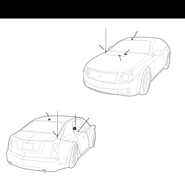
Your vehicle’s FM antenna will be located in one of seven common locations:
1. front fender
2. rear fender
3. roof top front
4. roof top rear
5. adhered to top of windshield
6. adhered to top of rear window
7. adhered to rear side glass (in some SUVs)
For best audio performance, install the XM SureConnect by either clipping it
directly to an external antenna (locations 1 through 4) or against an interior on-
glass antenna using the additional window Contact Bracket (locations 5 through
7). The remainder of this document provides step by step XM SureConnect instal-
lation instructions.
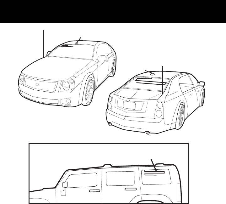
Installation Locations
5
1
3
5
4
6
2
7

TThhee ffoolllloowwiinngg sstteeppss wwiillll gguuiiddee yyoouu tthhrroouugghh tthhee iinnssttaallllaattiioonn ooff yyoouurr
XXMM SSuurreeCCoonnnneecctt
1. Install your XM Radio in your vehicle as described in your XM Radio
User Manual but do not connect the XM antenna plug to the dock
at this time.
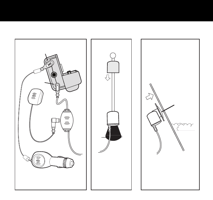
2. Locate your vehicles FM antenna and determine the best routing
method to get the XM SureConnect output cable to the FM antenna.
(For external antennas (Figure 1b), the Coupling Clip needs to be routed
outside the vehicle. For internal on glass antennas (Figure 1c), all rout
ing is inside the passenger compartment and the Contact Bracket is used.
3. To route the output cable with Coupling Clip to your vehicle FM antenna,
follow the instructions on the next pages . There are separate instructions
for external antenna vs the internal on glass antenna. Follow the instruc
tions that apply to your vehicle’s antenna type. (This guide assumes you
have already installed your XM antenna per the instructions in your XM
radio user guide. The positions of the XM antenna in the illustrations
below is for example only. There is no need to change your XM antenna
installation.)
4. Connect the XM Antenna to the XM SureConnect antenna input, locat
ed on the coupler module about 2 feet from the end of the input cable (see
Figure 1a). Tuck any excess input cable and the coupler module behind
dash or in another hidden location for a professional looking installation.
5. Connect the XM SureConnect input cable to the XM radio or vehicle dock
antenna input.
Installation Setup
6
Installation Setup
7
no boot necessary
glass
contact
bracket
inside your
vehicle
outside
car dock
XM car
antenna coupling
clip
coupling
module
input
cable
output
cable
External AntennaConnecting the Components Internal on-glass antenna
boot
power
XM antenna
or
Figure 1a Figure 1b Figure 1c
Option 1: External FM Antenna Coupling Clip Installation
8
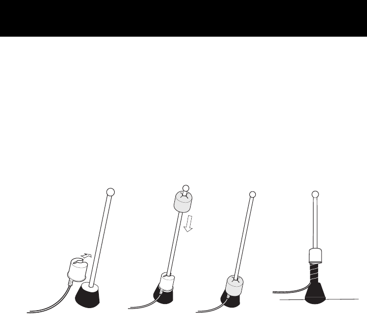
SStteepp 11::
If you have an external or roof mount FM antenna, attach the Coupling Clip
directly to the base of the antenna as illustrated in Figure 2. Cover the Clip
with the rubber boot provided to protect and secure the clip. Secure the cable
inside the trunk or hood to avoid interference or accidental damage. Installing
the Coupling Clip first will avoid having excess cable outside the vehicle.
a. Snap the antenna clip into place
b. Slide the boot over the top of your antenna.
c. Slide the boot down the antenna so it covers the clip
car
antenna
rubber
boot
coupling
clip
(a) (b) (c)
You may want to use the
optional cable wrap for
a more secure solution.
Figure 2
External FM Antenna Routing
9
In the front, route the cable across
the weather seal near the bottom
of the door to reduce water leaks.
Once inside the car tuck the XM
SureConnect output cable into the
door jam up to the dash or under
the carpet as shown in Figure 3.
XM car
antenna XM
receiver
coupler
clip
coupler
module
In the rear, Always cross the
weather seal at the lowest part of
the trunk to reduce water leaks.
Route the cable into the trunk
through available wire channels.
Route through the rear passenger
compartment. Tuck the cable under
the door jam trim or under the car-
pet to the XM Receiver as shown in
Figure 4.
XM car
antenna
XM
receiver
coupler
clip
coupler
module
Figure 3
Figure 4

10
Option 2: Internal On Glass FM Antenna Coupling Clip Installation
Identifying the On Glass FM Antenna
UUsseeffuull IInnffoorrmmaattiioonn ffoorr SStteepp 11::
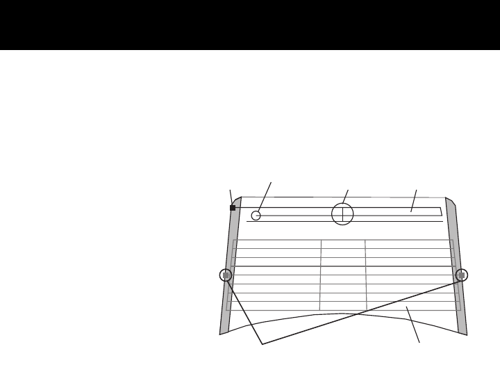
CCAAUUTTIIOONN:: Do not attach the contact bracket to the rear defogger elements.
In some vehicles they look similar to the FM Antenna.
1. The FM antenna is typically found on the top 6 to 8 inches of the rear
window with the Defogger is below.
2. The FM antenna has open ends (connected to nothing) and the
Defogger does not.
single
contact
dual contact
open ends vertical
element non-uniform
spacing
uniform spacing
FM Antenna
Rear Window
(may be hidden)
(may be hidden)
DO NOT PLACE ON DEFOGGER
Option 2: Internal On Glass FM Antenna Coupling Clip Installation
11
You can distinguish the FM
Antenna Elements from the
Defogger Elements by sever-
al key features. See Figure 5
Figure 5

Internal On Glass FM Antenna Coupling Clip Installation
12
3. The FM antenna will have a single contact point and the Defogger will have
two, which are typically on opposite sides of the window. (The contact
points may be hidden behind interior liners or exterior glass tinting but the
key is to locate where the elements go off the window edge. The FM anten
-na will have only one location while the defogger can have two or more.
Step 1:
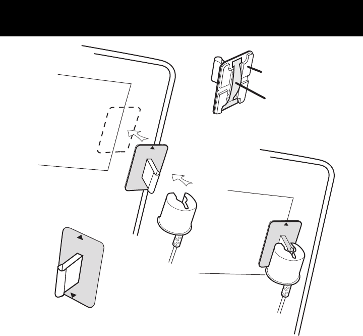
Install the Contact Bracket on the interior window surface over the antenna element
using the adhesive pad provided and the following steps. It may be mounted either
vertical or horizontal depending on the portion of the antenna element most easily
accessed. Select a bracket position that allows room to attach the Coupling Clip and
cleanly run cables. Install the on glass antenna coupling clip before routing the
cable to avoid excess cable. See Figure 6.
a. Clean the mounting location on the glass for the Contact Bracket with any
household window cleaner that will remove grime. Be sure the surface is
completely dry before proceeding.
b. Remove the red liner from the adhesive pad and press the Contact Bracket
firmly at the identified mounting location on the glass. You can also view the
alignment through the glass from outside the vehicle.
c. The Contact Bracket has alignment arrows on the side opposite the adhesive
pads. These arrows indicate the contact strip location on the base of the brack
-et. Align the arrows with the on glass antenna element to ensure direct con
tact between the strip and the element. Press and hold the Contact Bracket in
place for 10 to 15 seonds.
d. Once the Bracket is in place, attach the Coupling Clip to the flange on the
Bracket and route any excess cable behind liners for a professional look.
Internal On Glass FM Antenna Coupling Clip Installation
13
contact bracket with
arrows for alignment
contact strip
adhesive pads
antenna element in
glass
no boot
required
(a)
(b)
(c)
(d)
Figure 6
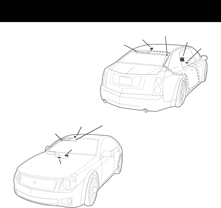
Internal On Glass FM Antenna Routing
coupler clip
with contact
bracket
internal on
glass
antenna
XM car
antenna XM
receiver
coupler
module
Step 2:
In the rear, route the XM
SureConnect output cable
from the antenna element,
along the window edge, down
to the window liner. From the
rear passenger compartment
tuck the cable under the carpet
or door jam trim up to the
front dash to the XM Receiver.
See Figure 7.
XM car
antenna
XM
receiver
coupler clip
with contact
bracket
internal on glass
antenna
coupler
module
In the front, route the XM
SureConnect output cable from
the antenna element, along the
window edge, down to the win-
dow liner along the floor and up
to the dash as shown in Figure 8.
Figure 7
Figure 8
14

NNoottee:: When routing the XM SureConnect cable use pre-existing wire channels
whenever possible to avoid loose wires on the interior of the vehicle which are
susceptible to damage and to maintain a professional looking installation.
Route cable carefully by taking notice of how doors open and close, as well as
how seats move when they are adjusted so you can be certain there is ample
clearance provided for the cable.
Avoid inadvertent damage that may be caused by kinking, crimping, twisting or
chafing the cables. Secure and tie wrap the excess cable under your dash
board, between the seat and the console, or on the floor under a seat or floor
mat. Securing the excess cable will help to prevent it from interfering with the
everyday use of your vehicle, improve the appearance of the installation, and
avoid any undesirable accidental damage to the cables that might result in loss
of satellite signal or XM SureConnect performance.
Other Helpful Tips:
- When attempting to remove the XM SureConnect from either method of
installation, be sure to remove the “boot” first if applicable and pull the
Coupling Clip away by lifting from the end where the cable enters the clip.
Squeezing the Coupling Clip in the middle may pinch the contacts inside
and make removing the clip more difficult.
Additional Information
15