Sirius XM Radio SA10101B XM Satellite RX with FM Transmitter User Manual RoadyXT manual layout
Sirius XM Radio Inc. XM Satellite RX with FM Transmitter RoadyXT manual layout
Contents
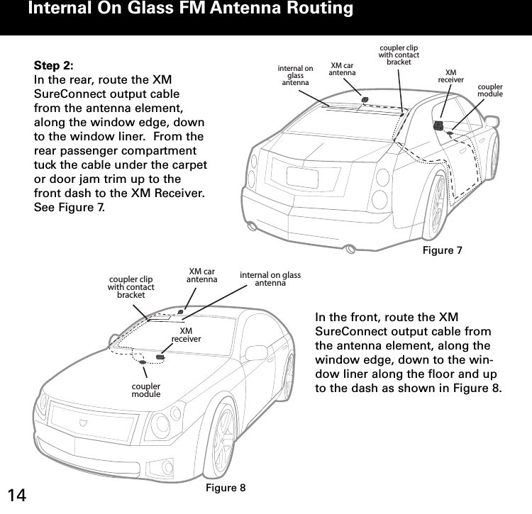
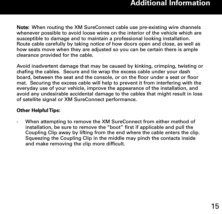
- 1. Sure Connect Users Manual
- 2. FM Direct Users Manual
- 3. Users Guide Revised
- 4. Install Guide
- 5. Quick Guide
Sure Connect Users Manual