Thales ATM 435 LICENSED NON-BROADCAST TRANSMITTER User Manual USERS MANUAL 1
Thales ATM LICENSED NON-BROADCAST TRANSMITTER USERS MANUAL 1
UserManual.wiki
>
Thales ATM
>
435 User Manual
>
USERS MANUAL 1
Contents
1.
USERS MANUAL 1
2.
USERS MANUAL 2
USERS MANUAL 1
Navigation menu
Upload a User Manual
Namespaces
Wiki Guide
HTML
PDF
Info
Views
User Manual
Discussion / Help
Navigation
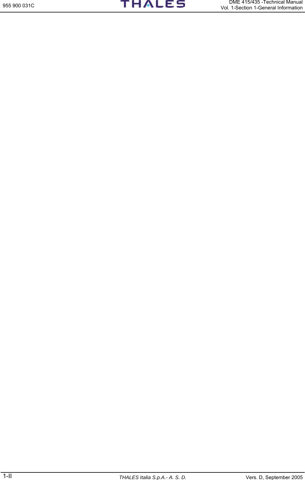
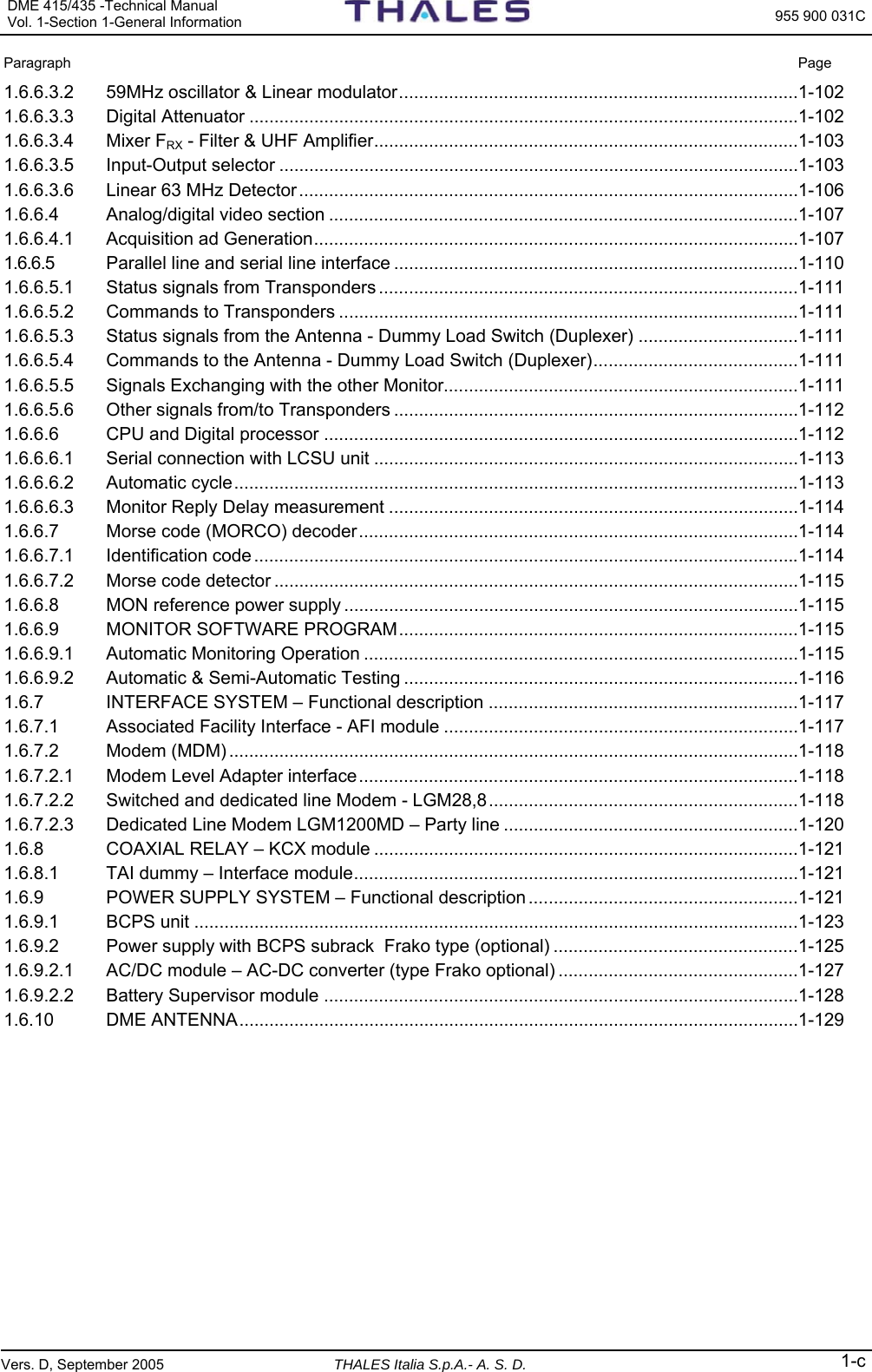
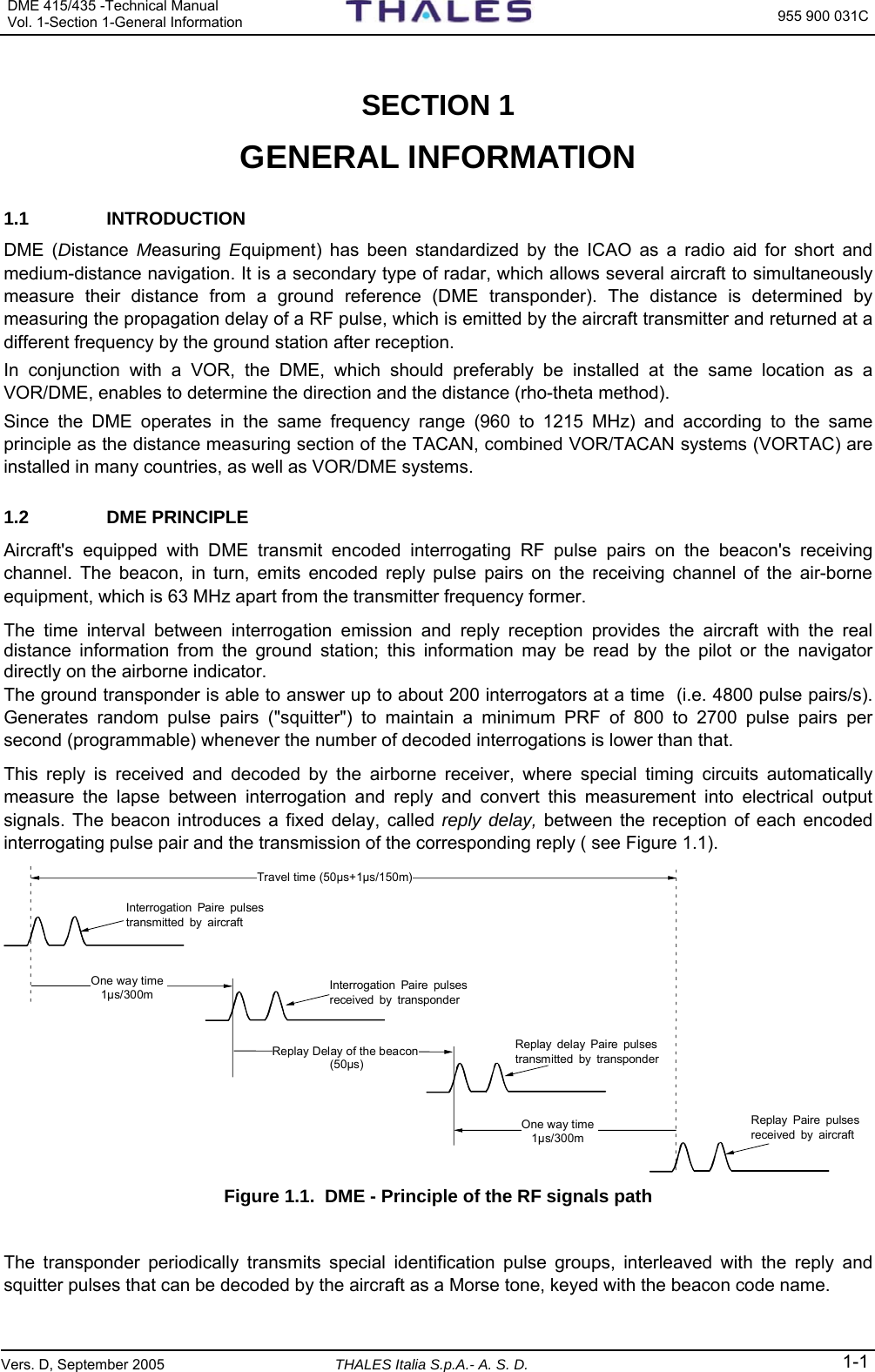
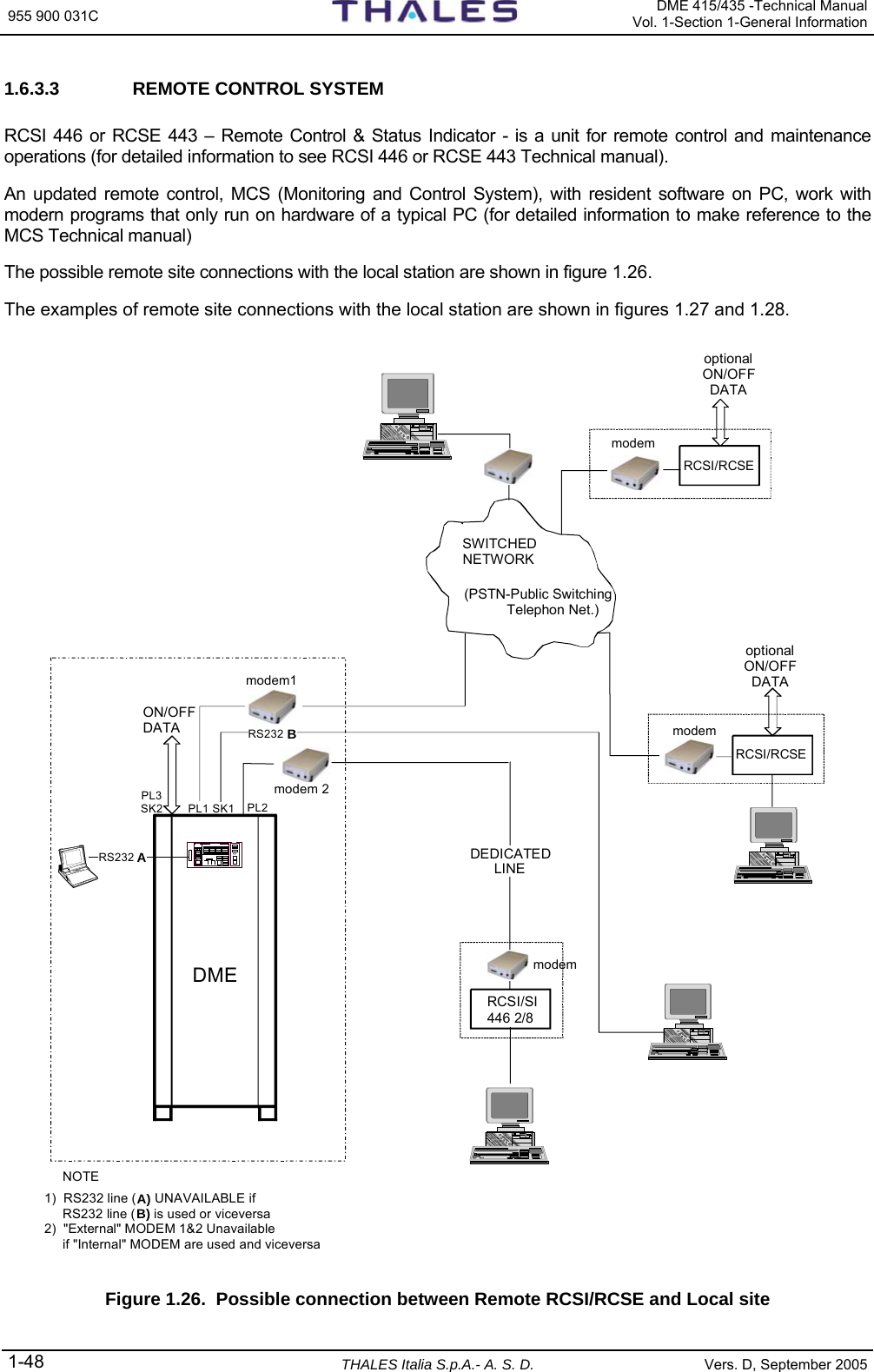
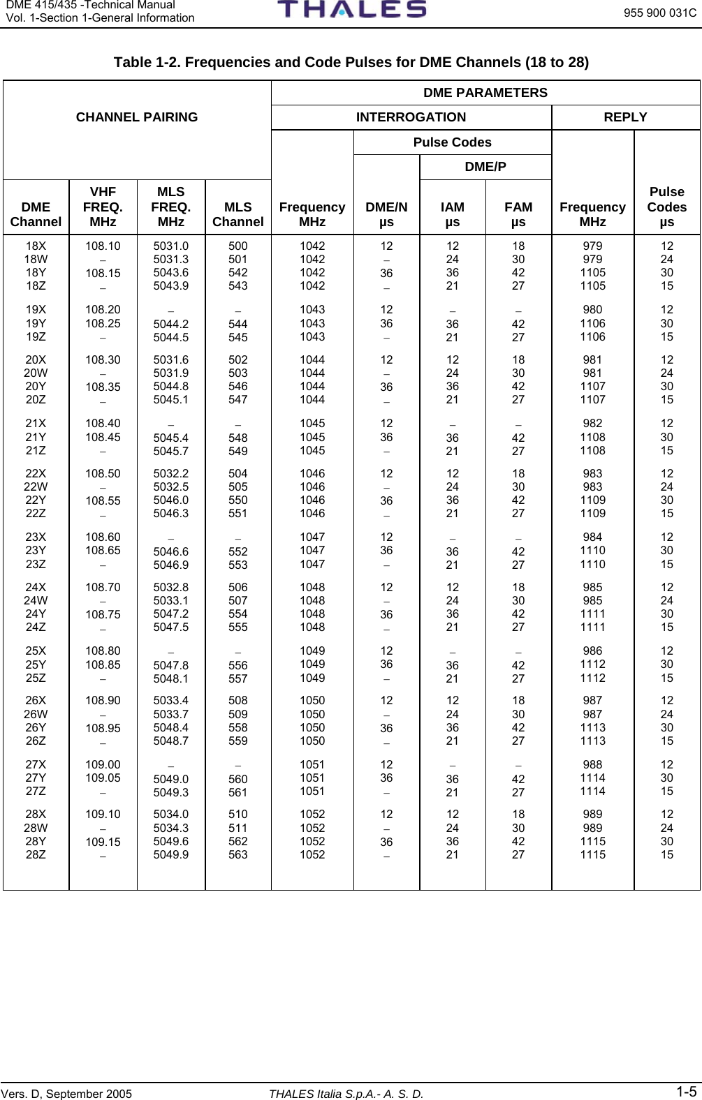
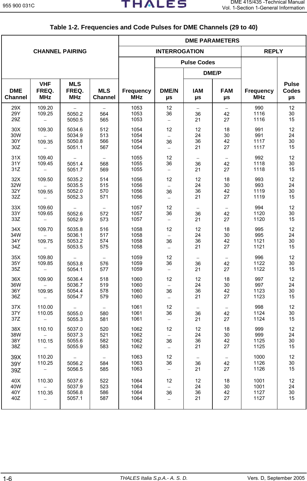
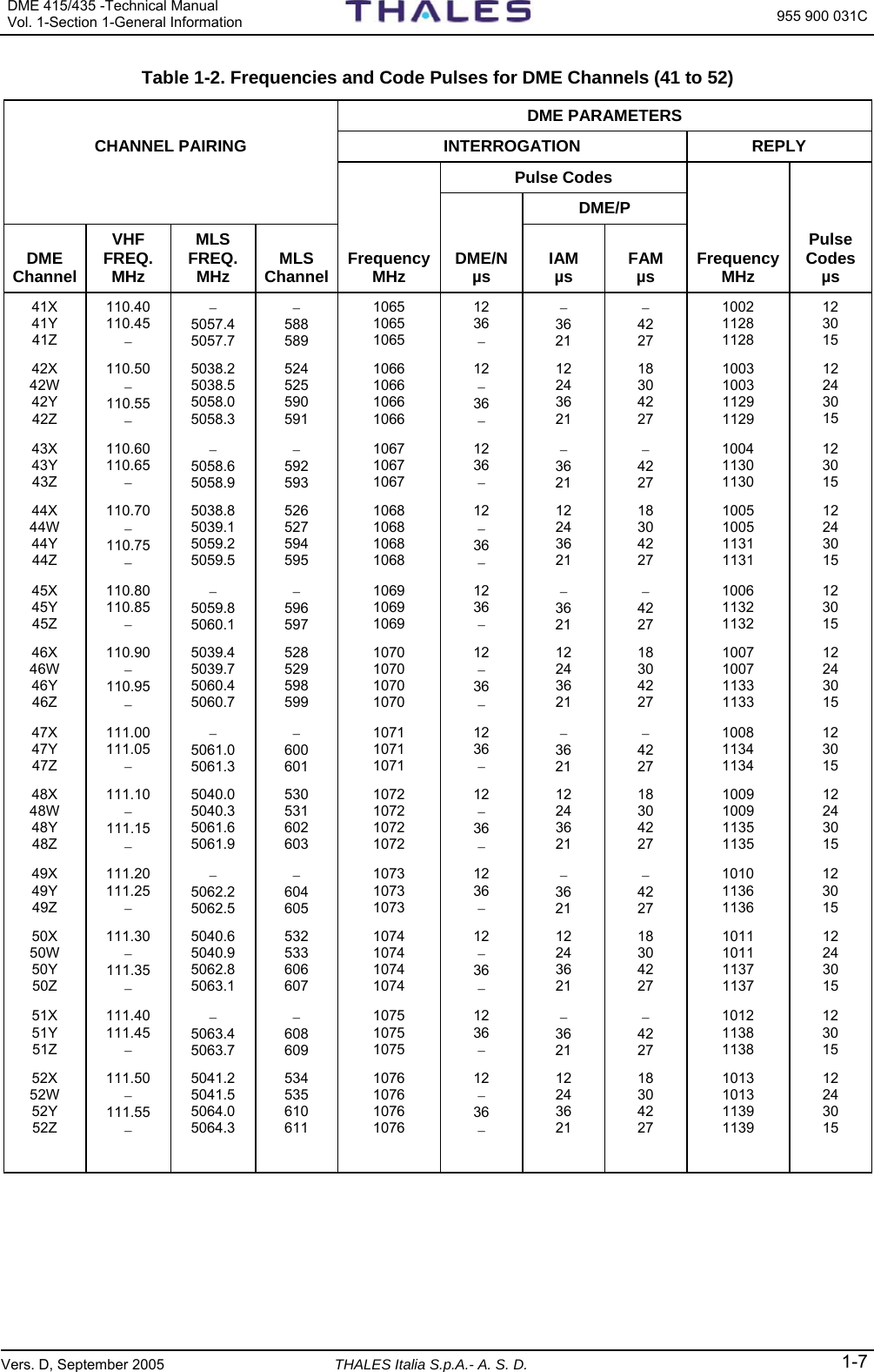
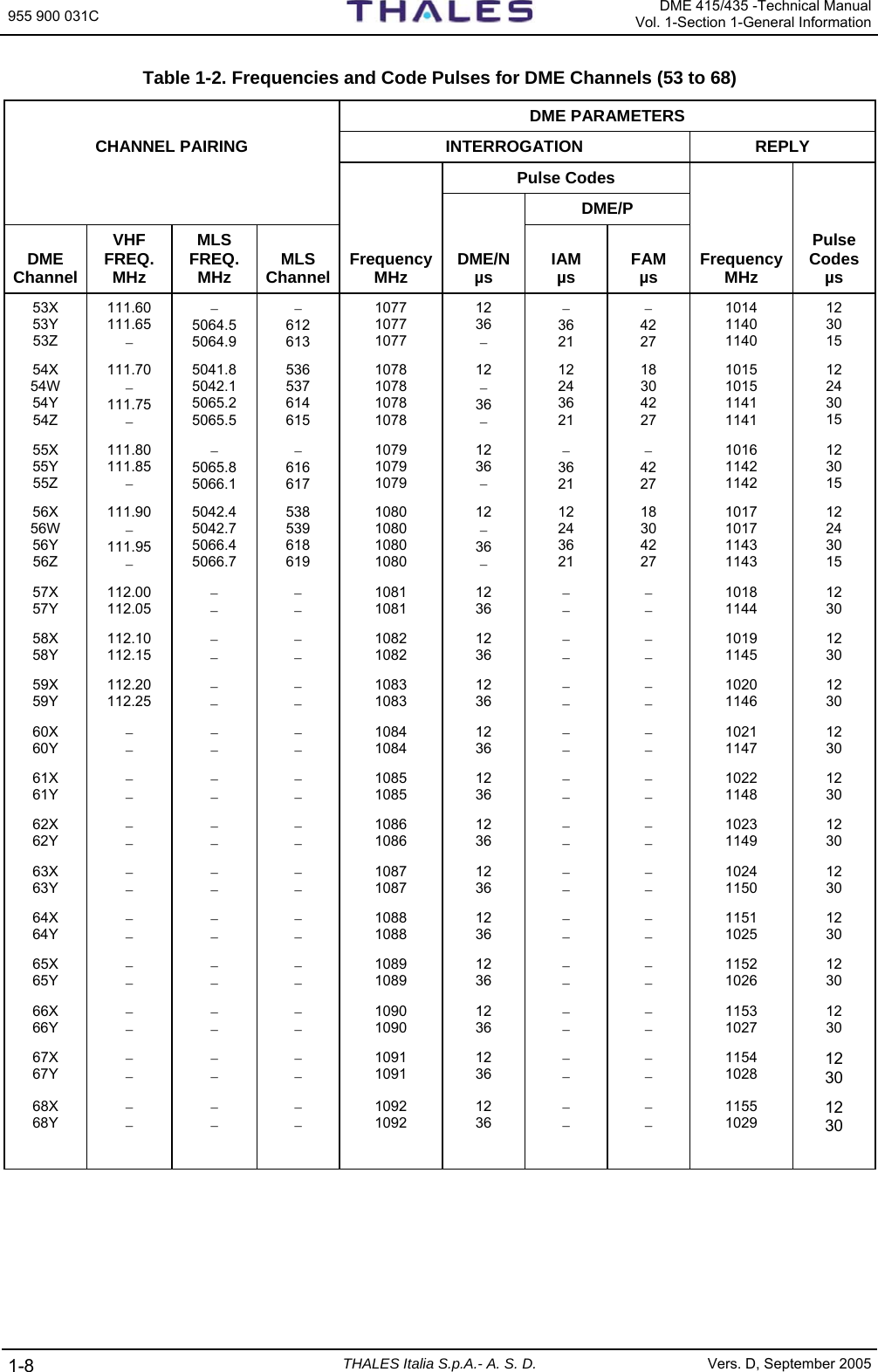
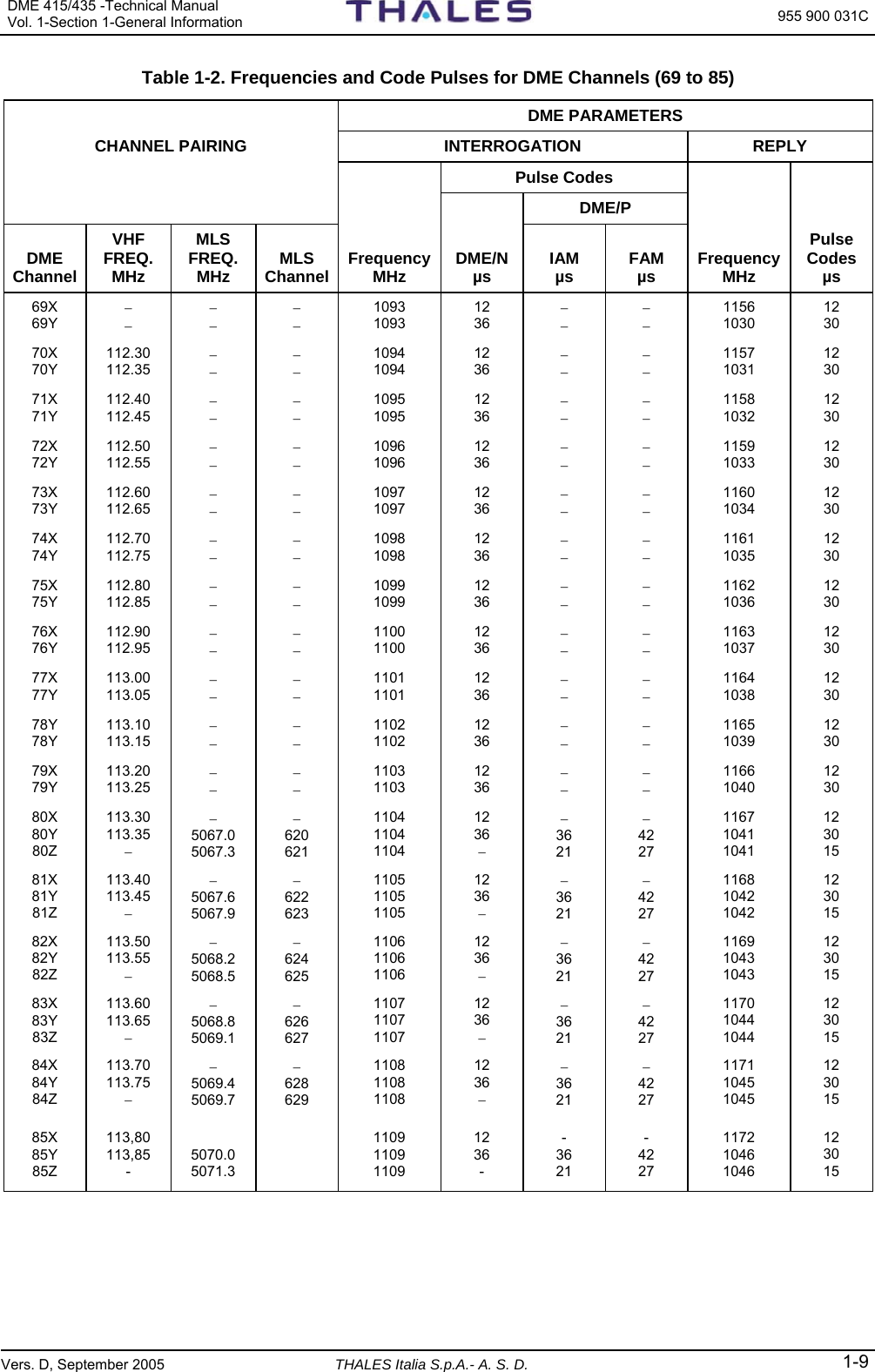
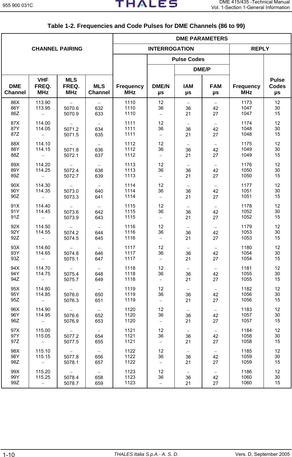
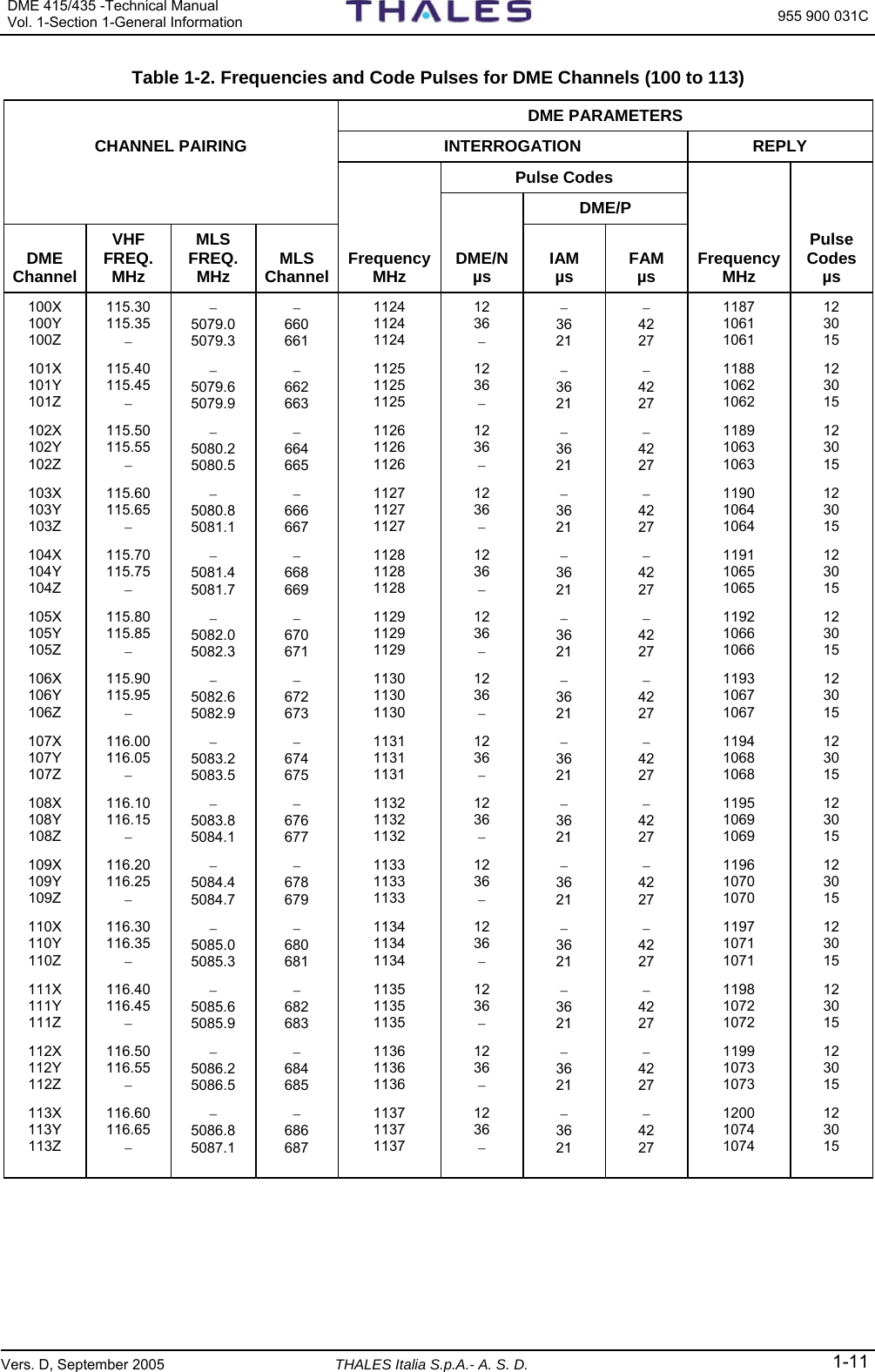
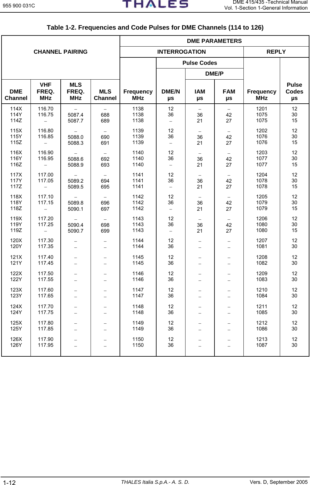
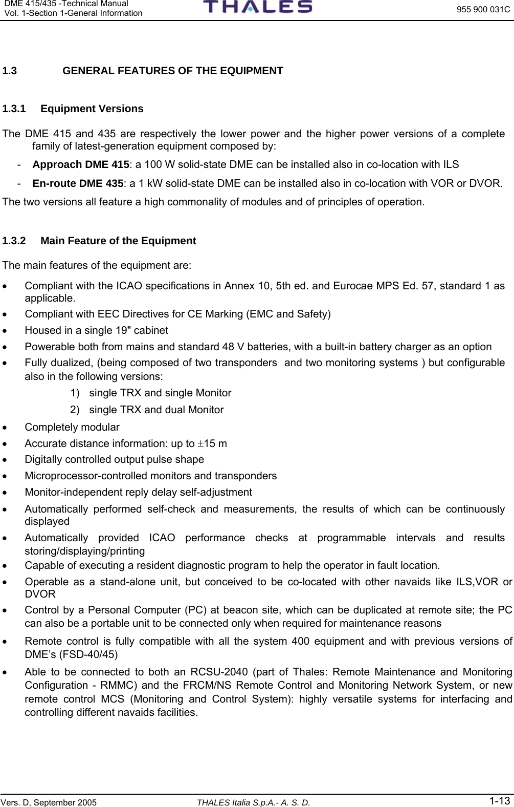
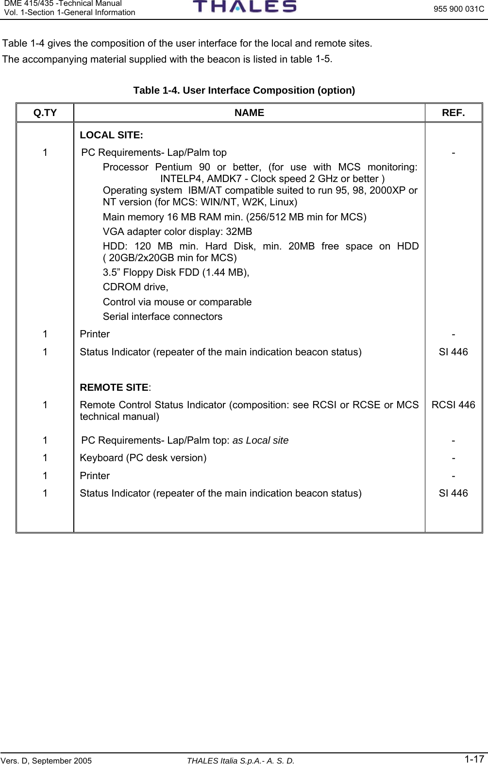
![955 900 031C DME 415/435 -Technical ManualVol. 1-Section 1-General Information 1-2 THALES Italia S.p.A.- A. S. D. Vers. D, September 2005 The airborne receiver is able to recognize the replies to its own interrogations, among the many other pulses transmitted by the beacon, by means of a stroboscopic procedure. The DME theory of operation is summarized in a block diagram in Figure 1.2. BEACONIDENTIFICATION TONETRANSMITTER RECEIVERAUTOPILOTTRANSMITTER RECEIVERDISTANCECIRCUITSDME AIRBORNE CHANNEL SELECTORDISTANCE INFORMATION TO BOARD INDICATORAIRCRAFT'SANTENNADME GROUND BEACONTRANSMITS DISTANCE INFORMATIONand IDENTIFICATION SIGNALREPLY TRIGGER TO INTERROGATIONSRECEIVEDINTERROGATIONSBEACON'SANTENNAINTERROGATION TRIGGERS Figure 1.2. DME - Theory of operation, simplified block diagram 1.2.1 Coverage According to the frequency band used, the DME system coverage is limited to the optical range and depends on the aircraft flight altitude and on the type of ground. The high frequency used and the use of special techniques have made the system much less sensitive to site errors than other types of omni-directional beacons now in use. 1.2.2 Traffic Capacity The aircraft handling capacity is adequate for a traffic peak of 200 aircrafts. When the traffic peak exceeds 200 aircrafts the transponder should be capable of handling that peak. 1.2.3 Accuracy As a result of the development and the applications of modern electronic technologies, the accuracy of the distance information provided by the DME system is improving all the time. At present, the accuracy of a DME system can be considered within the maximum values specified below: ±0.12 NM +0.05% of the distance, from 0 to 65 nautical miles, and ± 0.17 NM +0.05% of the distance, above 65 nautical miles. 1.2.4 Nominal Reply Delay – Pair Pulse Code - Channeling Each beacon is identified by means of its channel frequency, its pulse coding and its identity signal. The ground beacon introduces a fixed delay between the reception of interrogating pulses and the transmission of the corresponding reply pulses. This fixed delay, called main delay or fundamental delay, is introduced. So that an aircraft which is flying very close to the beacon can complete transmission of the encoded interrogating pulse pair, and then deactivate its own transmitter, before its receiver begins receiving the corresponding beacon reply pulses. To render the system as immune as possible to errors caused by interfering signals, the DME system transmits pulse pairs instead of single pulses; each pair includes two 3.5 µs pulses whose spacing depends on the channel mode selected. The channel code, pulse code, reply delay and operating mode are shown on the following table (standard ICAO). Channel Code Nominal Interrogation Pulse Code [µs] Transponder Reply Pulse Code [µs] Transponder Nominal Reply Delay [µs] X 12 12.0 ± 0.1 50 Y 36 30.0 ± 0.1 56](https://usermanual.wiki/Thales-ATM/435.USERS-MANUAL-1/User-Guide-857502-Page-10.png)
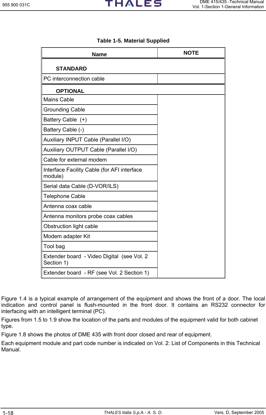
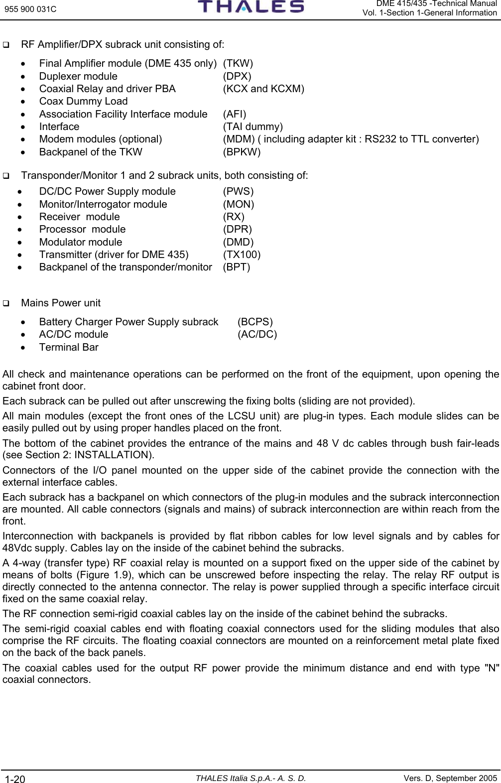
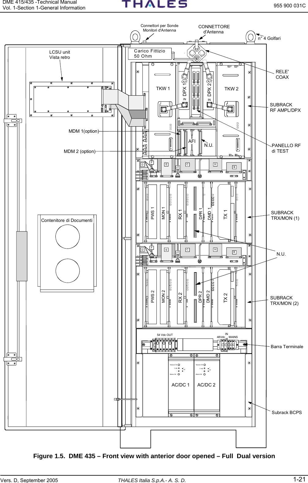
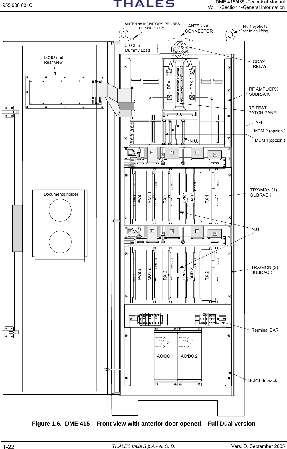
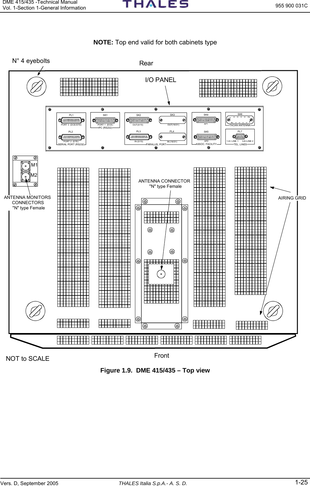
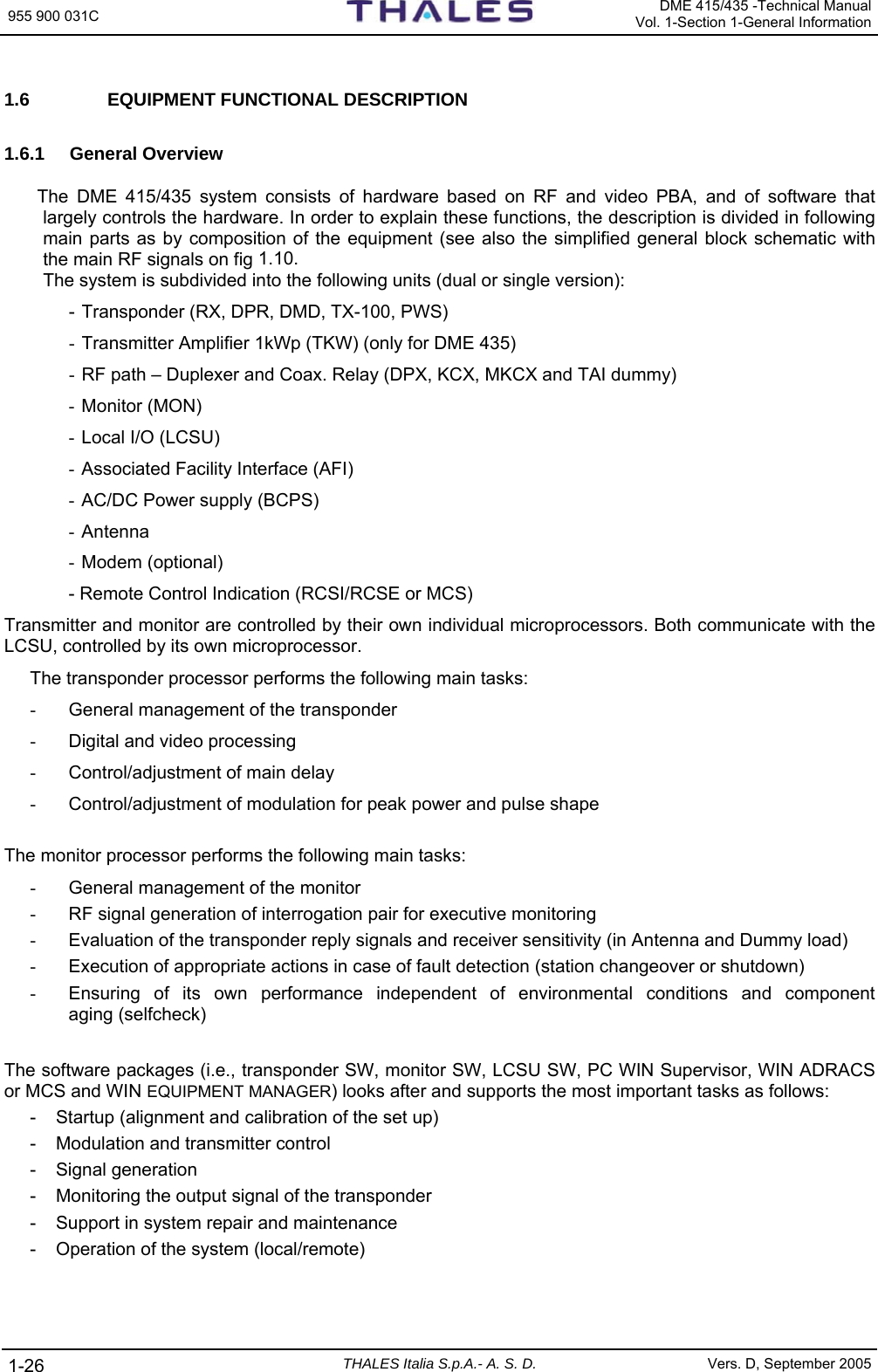
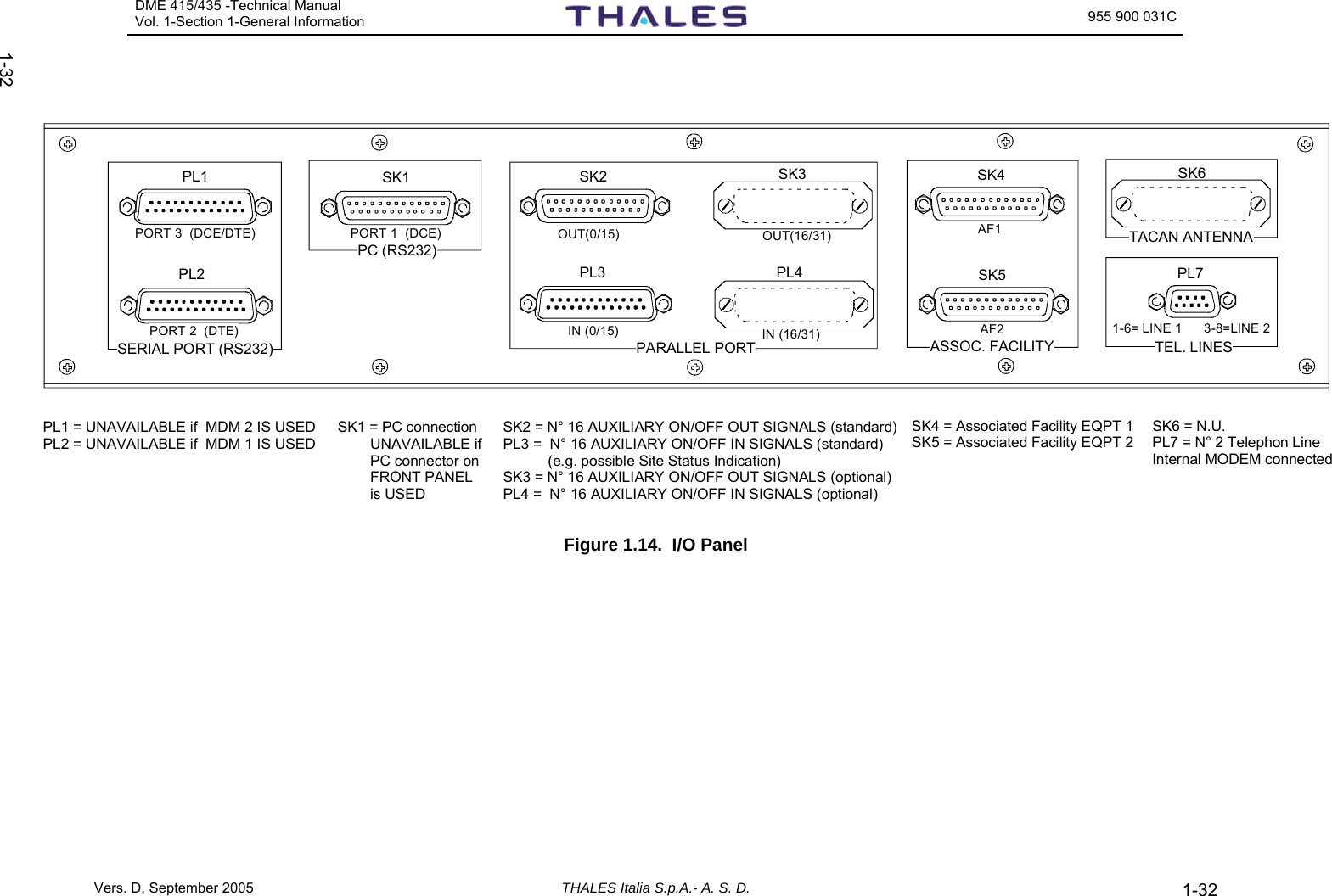
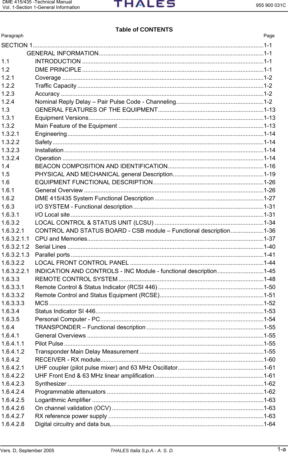
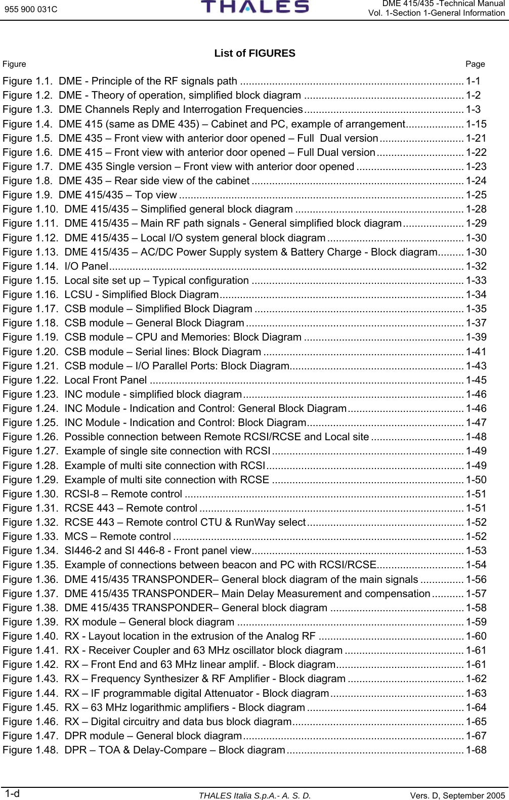
![DME 415/435 -Technical Manual Vol. 1-Section 1-General Information 955 900 031C Vers. D, September 2005 THALES Italia S.p.A.- A. S. D. 1-19 1.5 PHYSICAL AND MECHANICAL General Description The standard (full dual) configuration of the DME 415-435 equipment is composed of two transponders, a dual monitor system a RF path system, a Panel Control and a coaxial transfer relay unit. The parts of the equipment are housed in a single 19" standard cabinet (cabinet’s types: view in fig. 1.4). The cabinet, which is made of molded and welded steel sheet, can accommodate four 19” assembled carriers (subracks). Plug-in units are used as double or single Euroform printed circuit boards, with dimensions of 233.4 x 220 [mm] or 100 x 220 [mm]. The cabinet, which has a perforated metal plate on top and bottom, is self-ventilated (no forced ventilation necessary). NOTE: Do not block or seal the holes for the cooling air supply. The front part of the cabinet is protected by a hinged door complete of locking mechanism and the Control front Panel (Local I/O). The top end of the cabinet provides four threaded holes used to screw in the eyebolts when the beacon is to be lifted. The RF output connector to the antenna and the RF antenna monitor input connectors are located on top of the cabinet. The RF Duplexer modules are mounted inside of the "RF Amplifier/DPX" subrack on the upper part of the cabinet. The 1 kWp RF amplifier modules are mounted on the lateral sides of the same subrack, while the interface connections (e.g. modem, Associated Facility) are located on the bottom. The RF components of the modules are in shielded casting boxes. The Transponder/Monitor 1 and 2 subracks are located in middle part of the cabinet. The AC/DC power supply units are located on the bottom of the cabinet. The BCPS subrack (optional) comprises a terminal bar for mains and 48Vdc input. Local I/O components (LCSU consisting of CSB module and INC module) are fastened to the hinged front door in the upper part. The CSB board of the LCSU unit, combined with the INC module, is mounted on the rear of the front door. The local control front panel of the INC module part of LCSU unit is equipped with indicators and commands: − the indicators, for immediate check of beacon functioning and − the main commands, for beacon control (acquisition and release of control, powering on/off, transponder change over) without having to use the local PC. The I/O panel with the external interconnection connectors is located in the top end of the cabinet (figure 1.9) The front view of the DME 415 and DME 435 equipments, with the open door, is shown in figures 1.5 and 1.6. These figures show the positions of all the modules, which compose the equipment in the typical full (or dual) version. For special purposes, the equipment can be supplied in a single, non-redundant version, where very high system availability is not mandatory. Figure 1.7 shows the typical single version of the DME 435 equipment. The single version of the DME 415 is the same as the DME 435 in which the final RF amplifier "TKW" module is removed. The DME 415-435, dual or full version, is composed of a wired cabinet housing the following hardware parts and modules: Local I/O • Local Control and Status Unit (LCSU) composed of − Control Status Board module (CSB) − Indication and Control module (INC) • I/O Panel (on top of the cabinet)](https://usermanual.wiki/Thales-ATM/435.USERS-MANUAL-1/User-Guide-857502-Page-27.png)