Thales ATM 435 LICENSED NON-BROADCAST TRANSMITTER User Manual USERS MANUAL 2
Thales ATM LICENSED NON-BROADCAST TRANSMITTER USERS MANUAL 2
UserManual.wiki
>
Thales ATM
>
435 User Manual
>
USERS MANUAL 2
Contents
1.
USERS MANUAL 1
2.
USERS MANUAL 2
USERS MANUAL 2
Navigation menu
Upload a User Manual
Namespaces
Wiki Guide
HTML
PDF
Info
Views
User Manual
Discussion / Help
Navigation

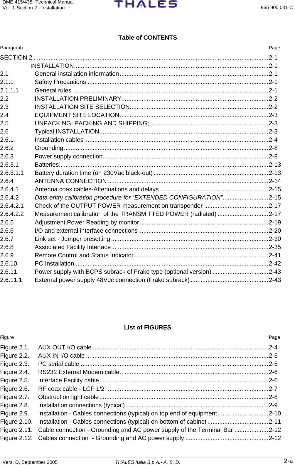
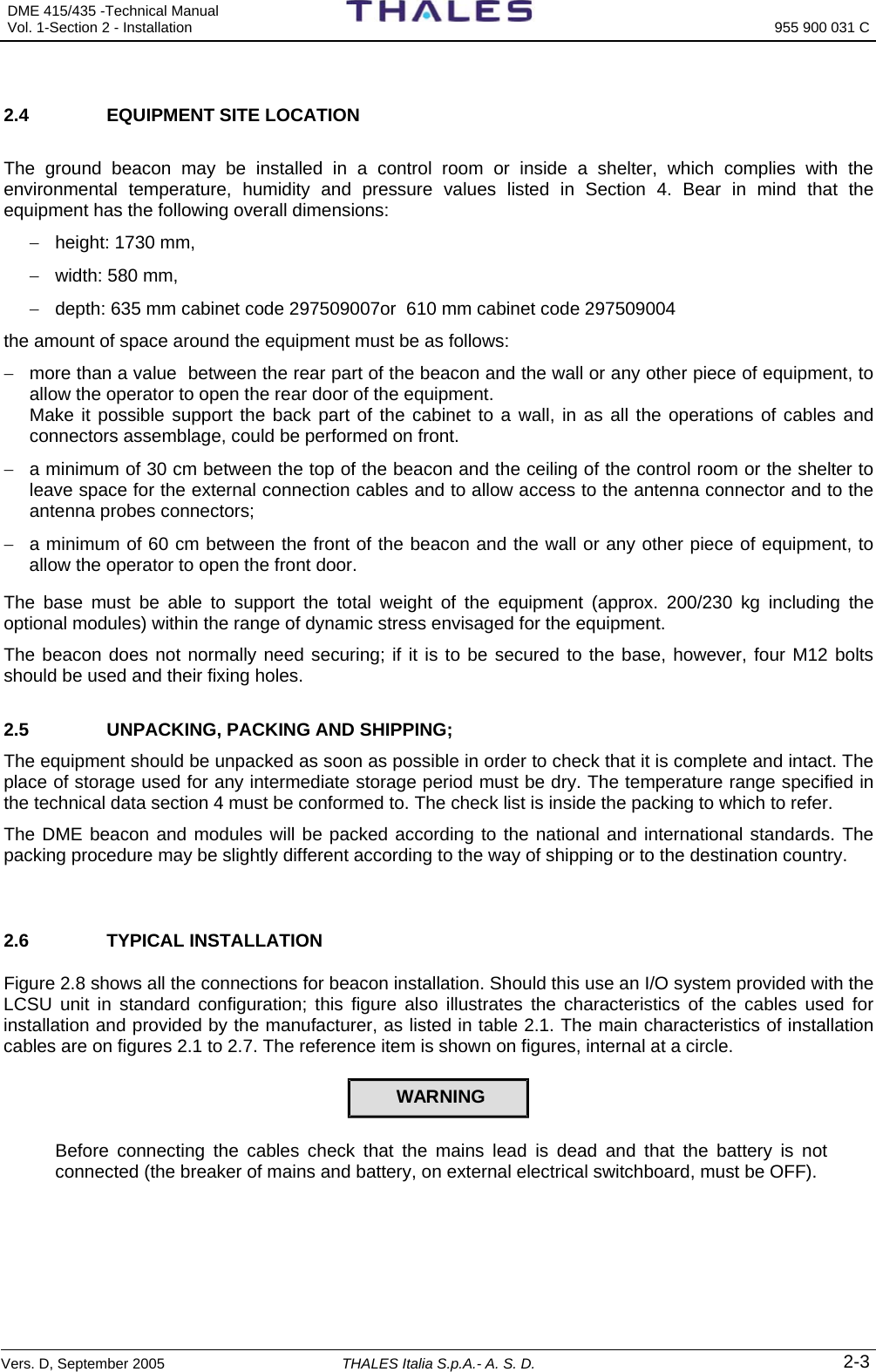
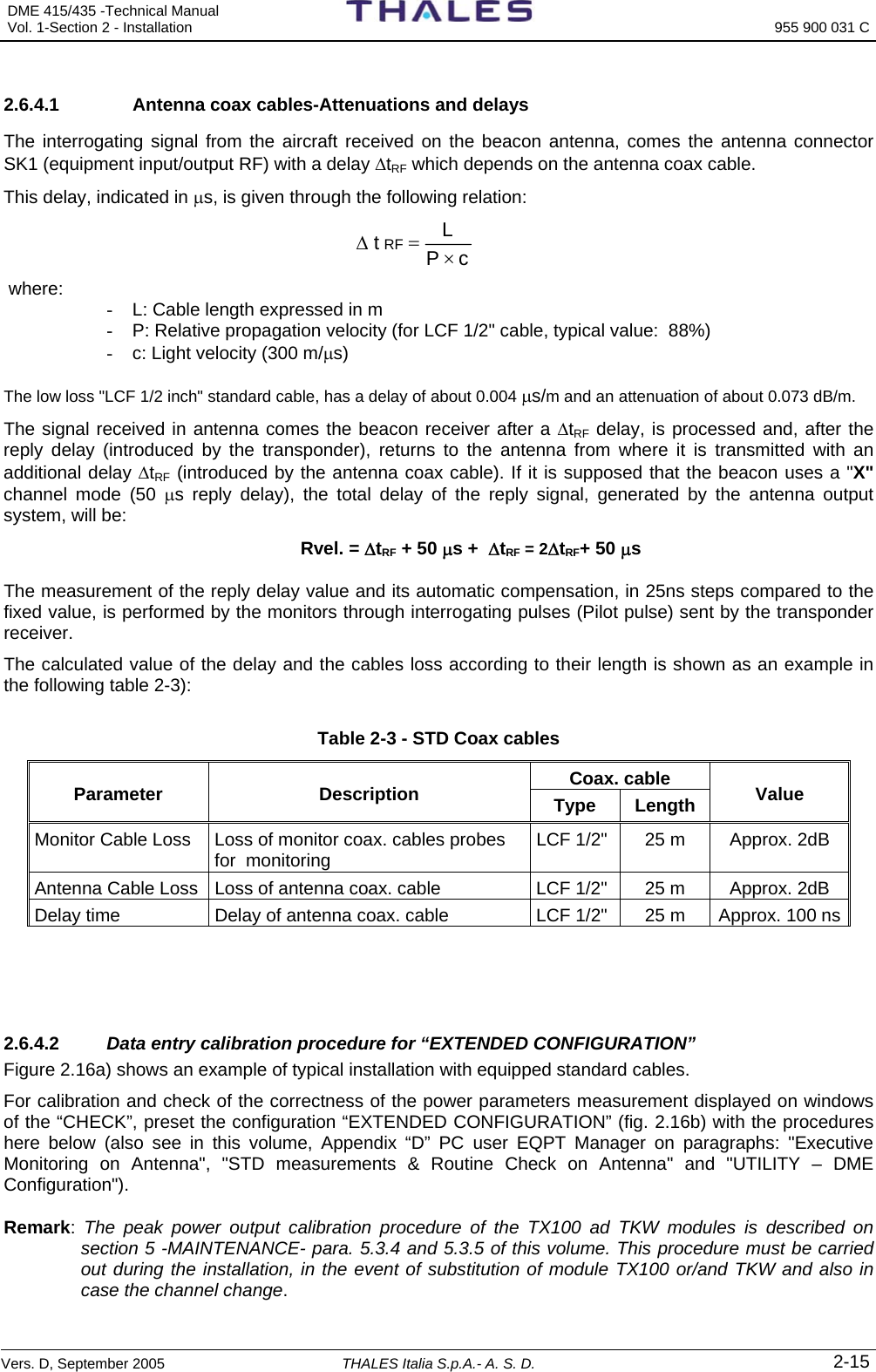
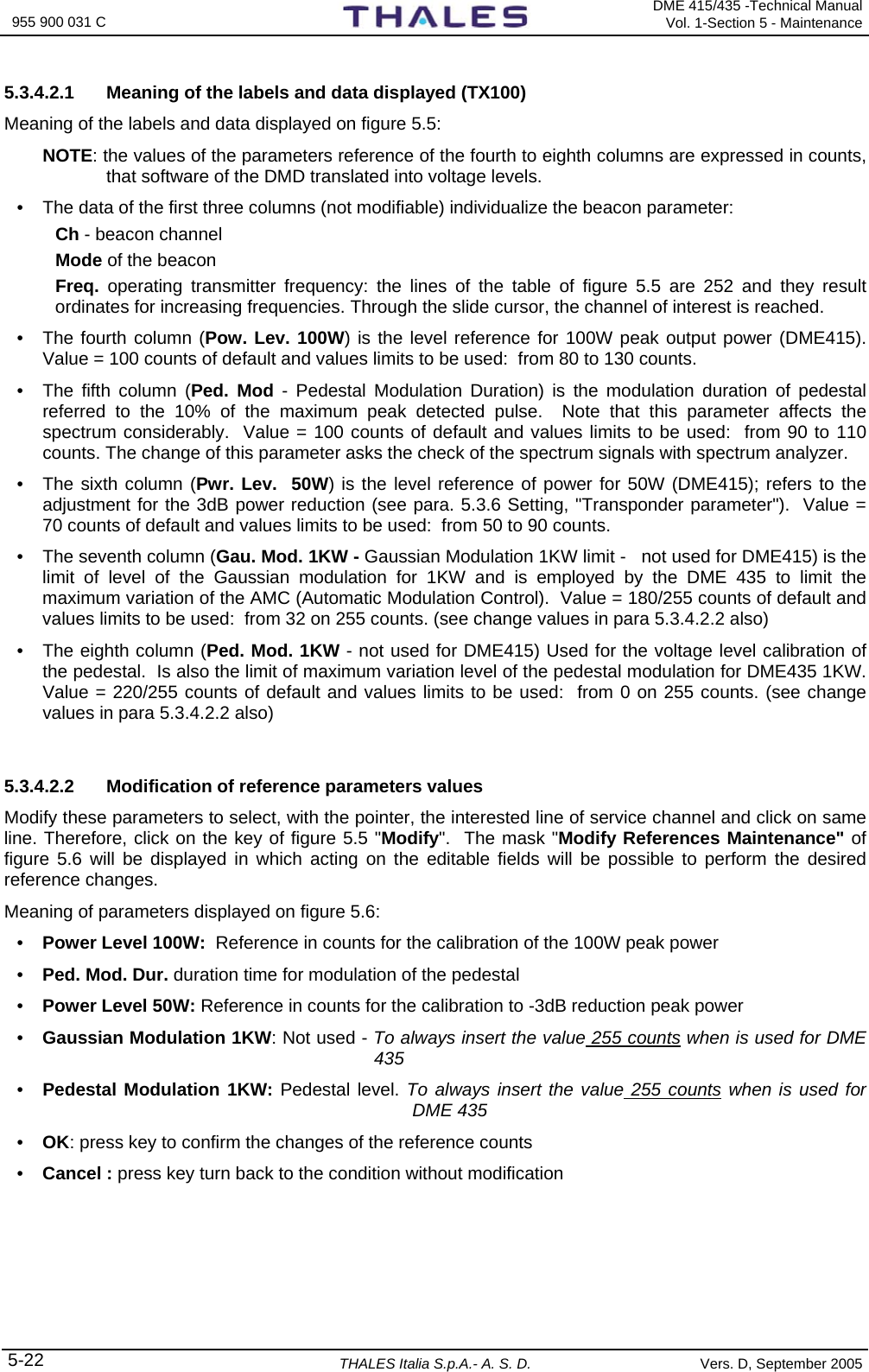
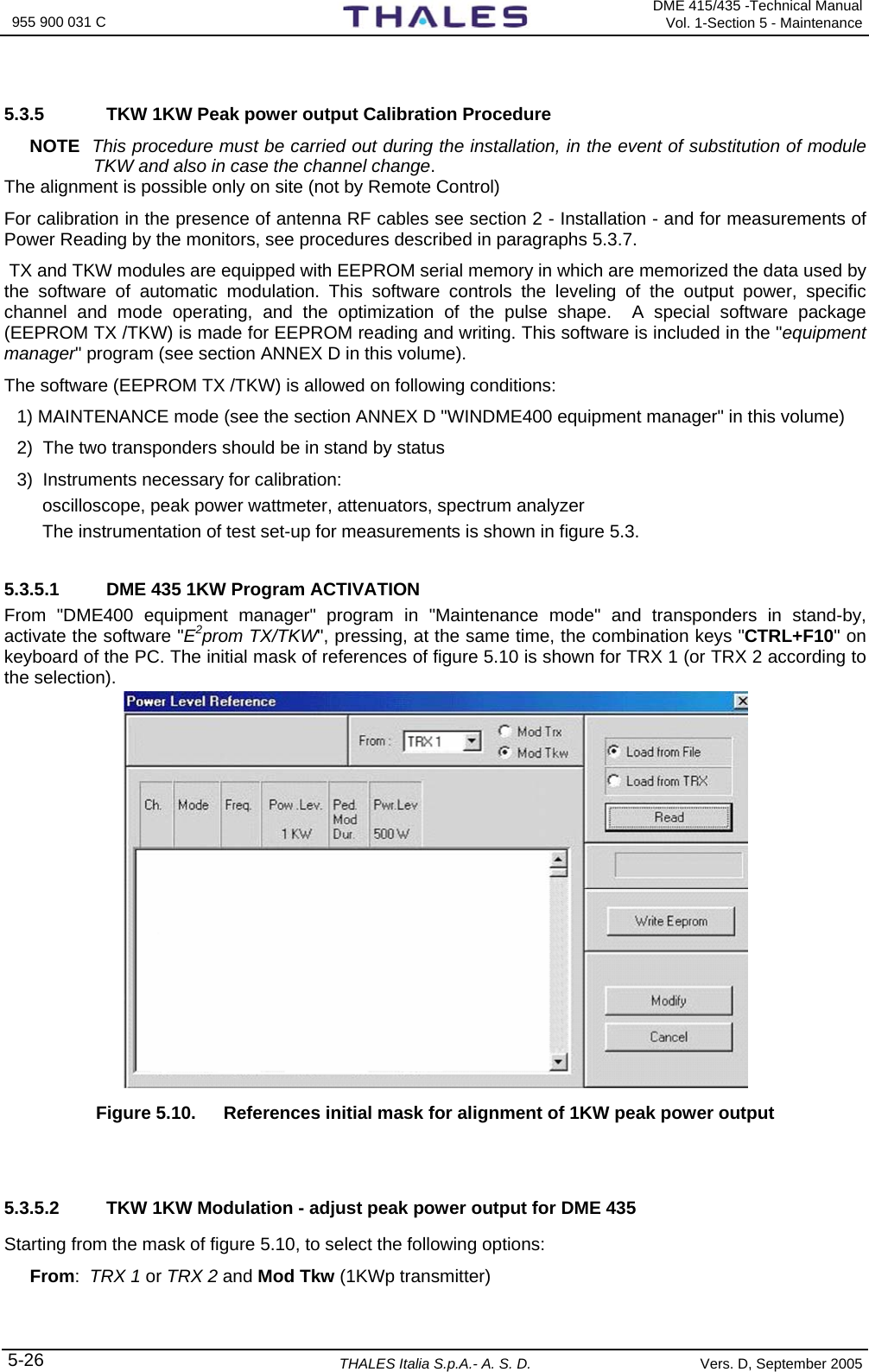
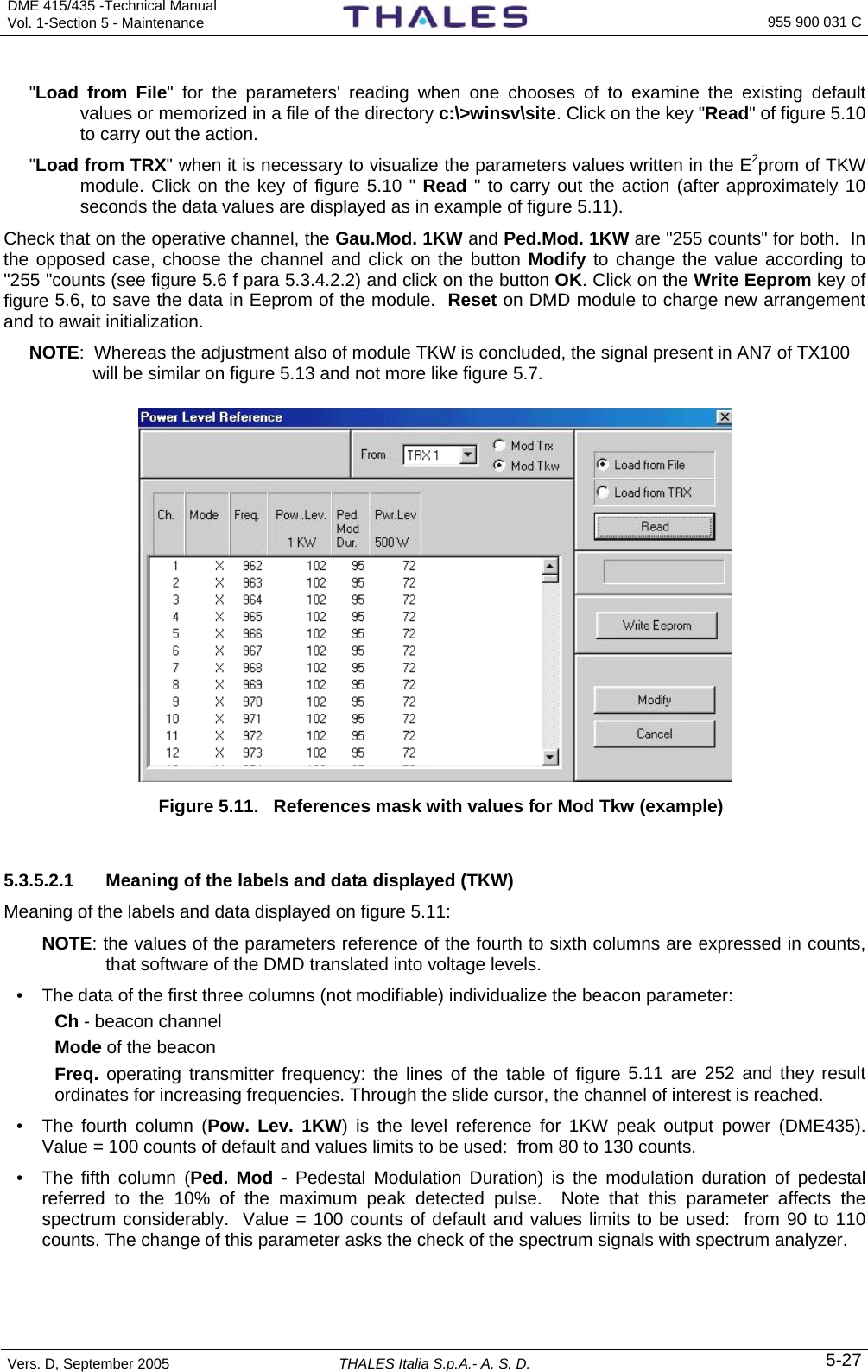
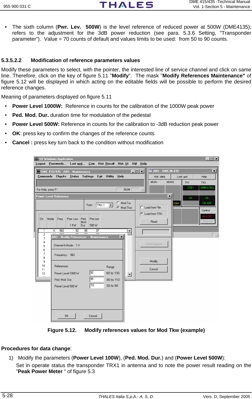
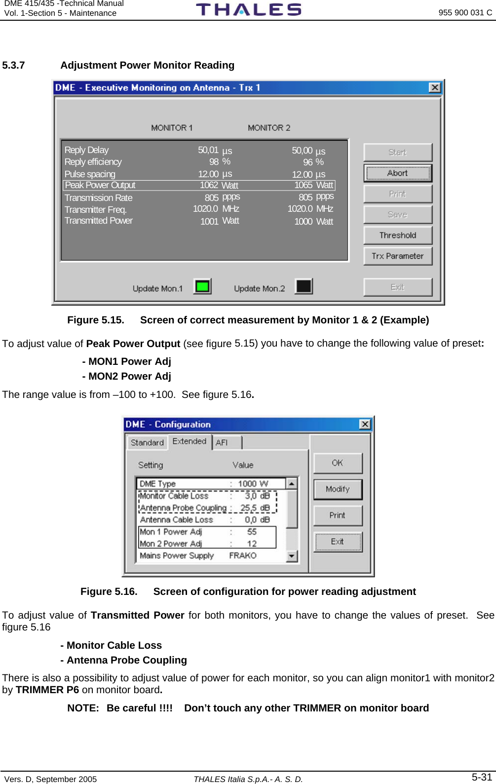
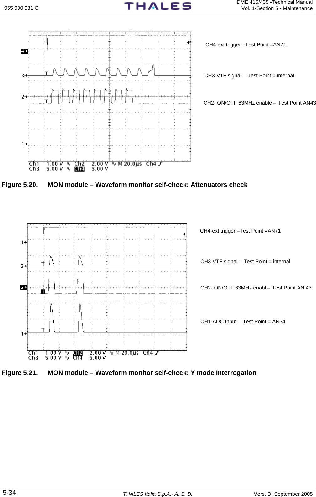
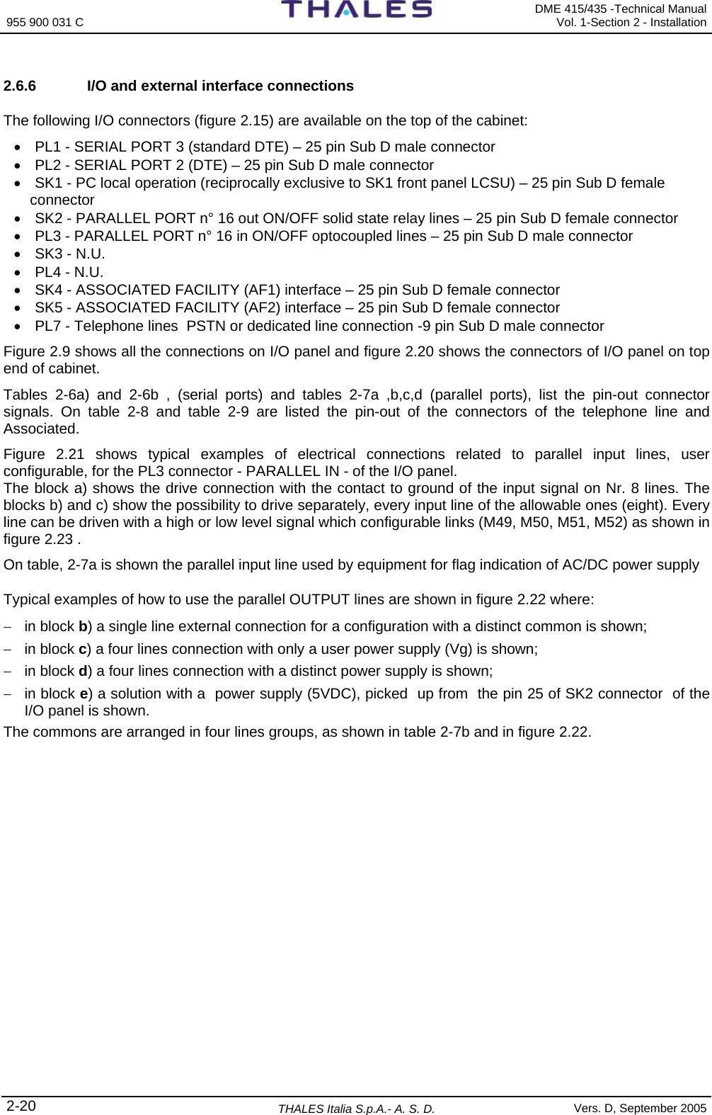
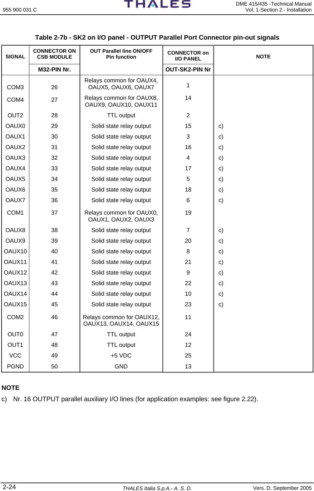
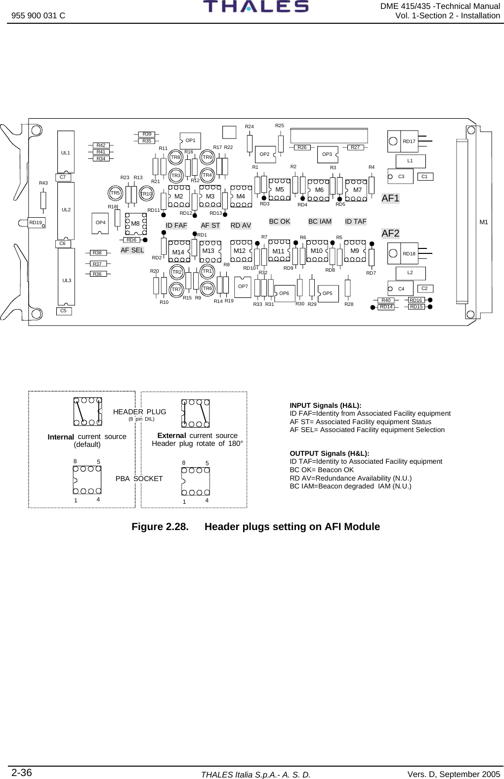
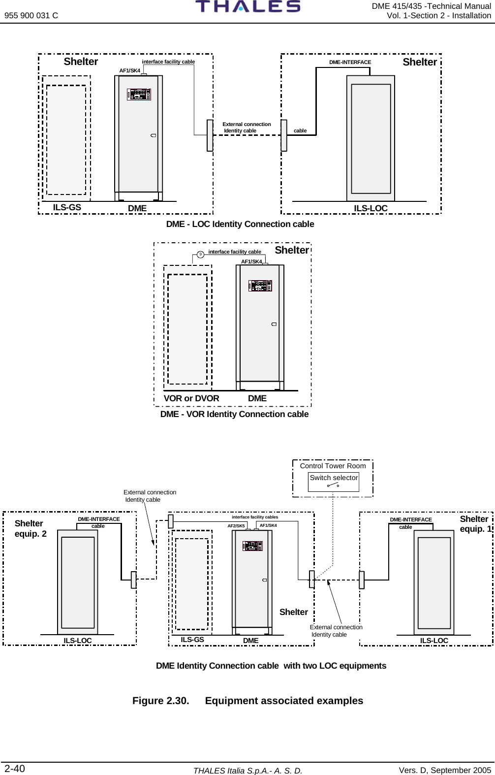
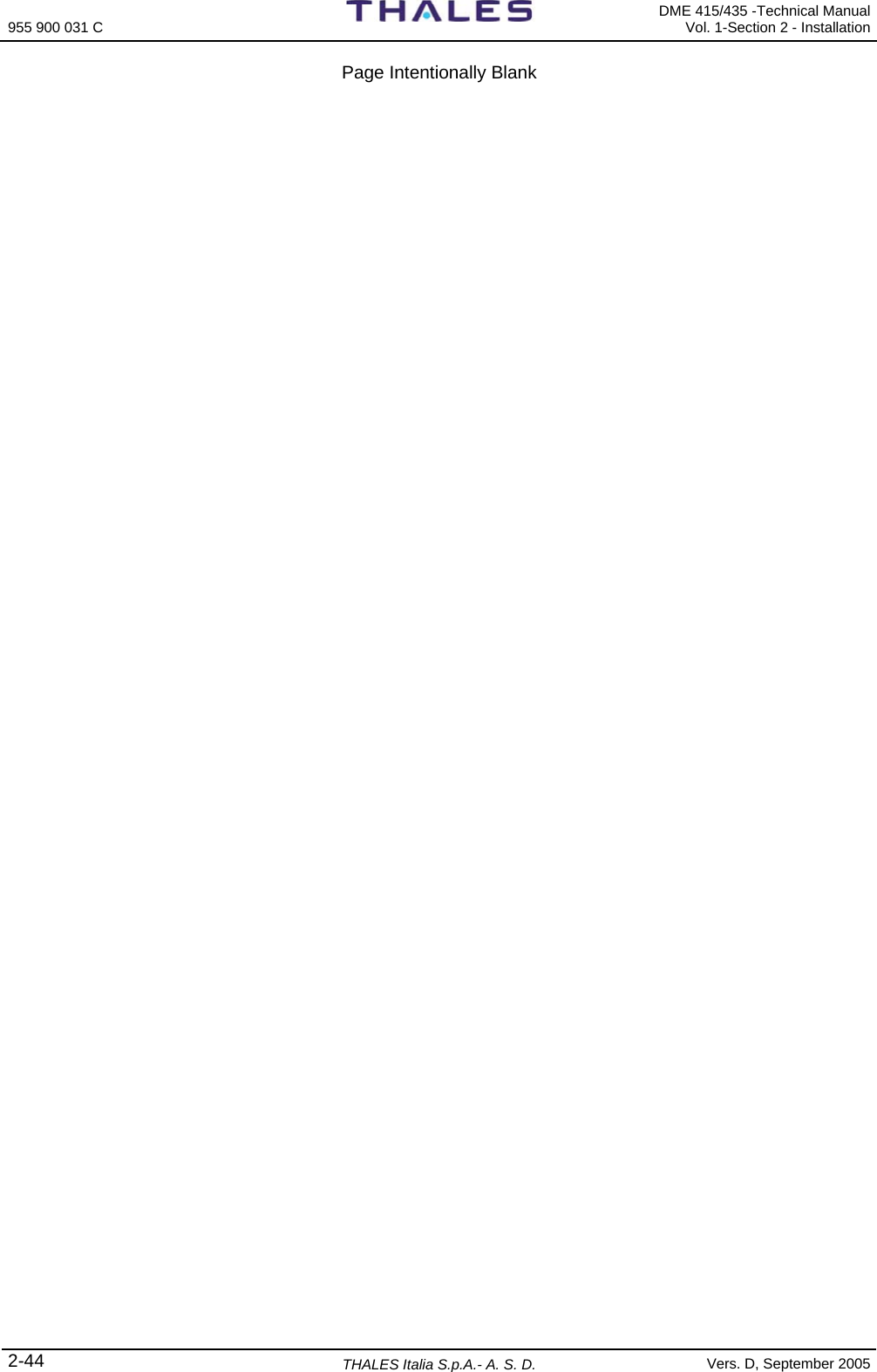
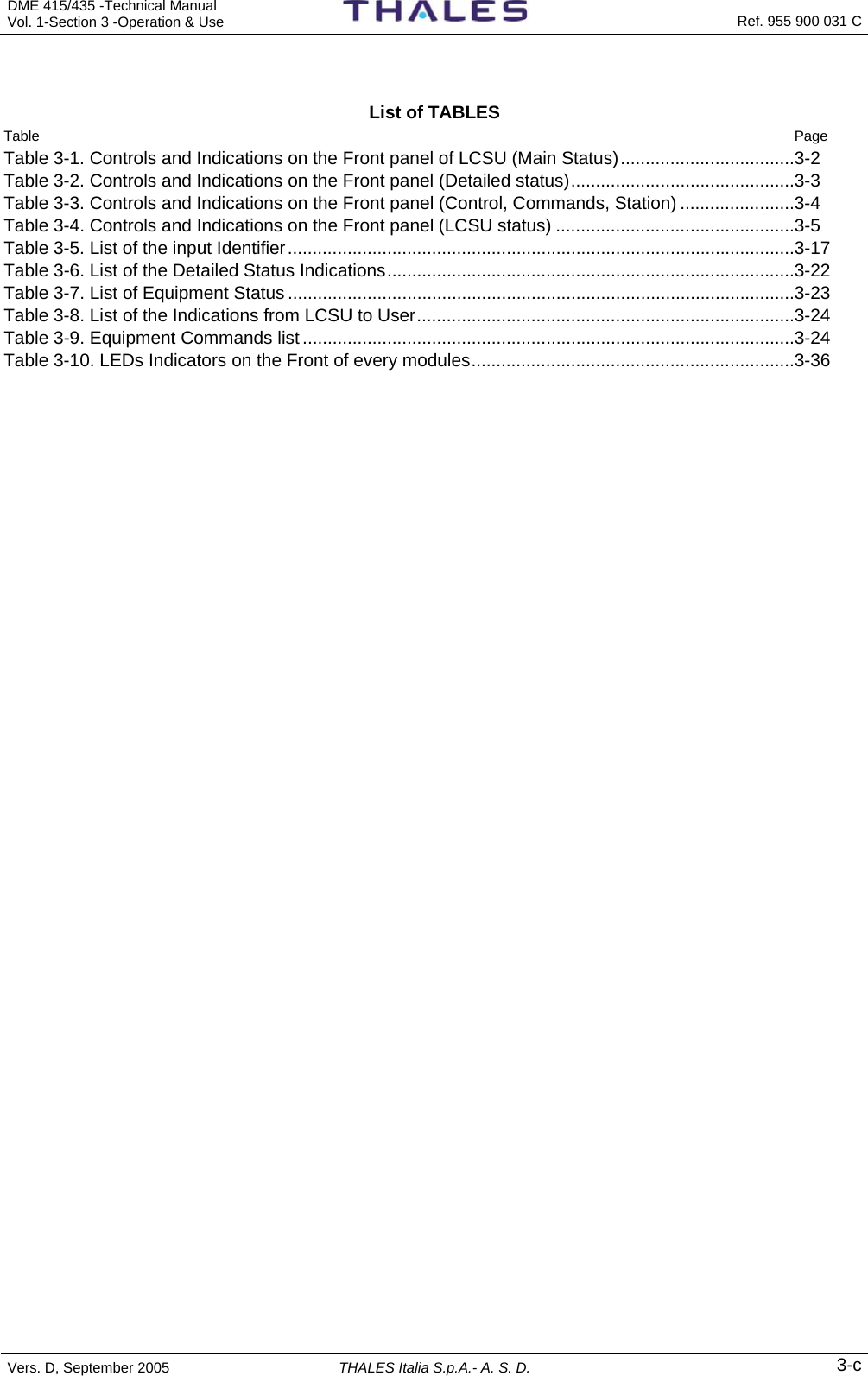
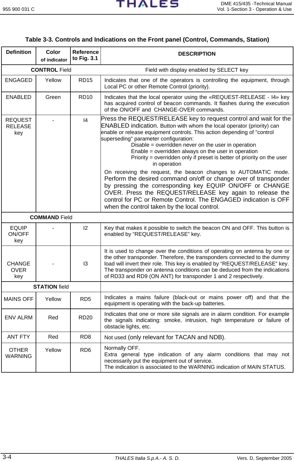
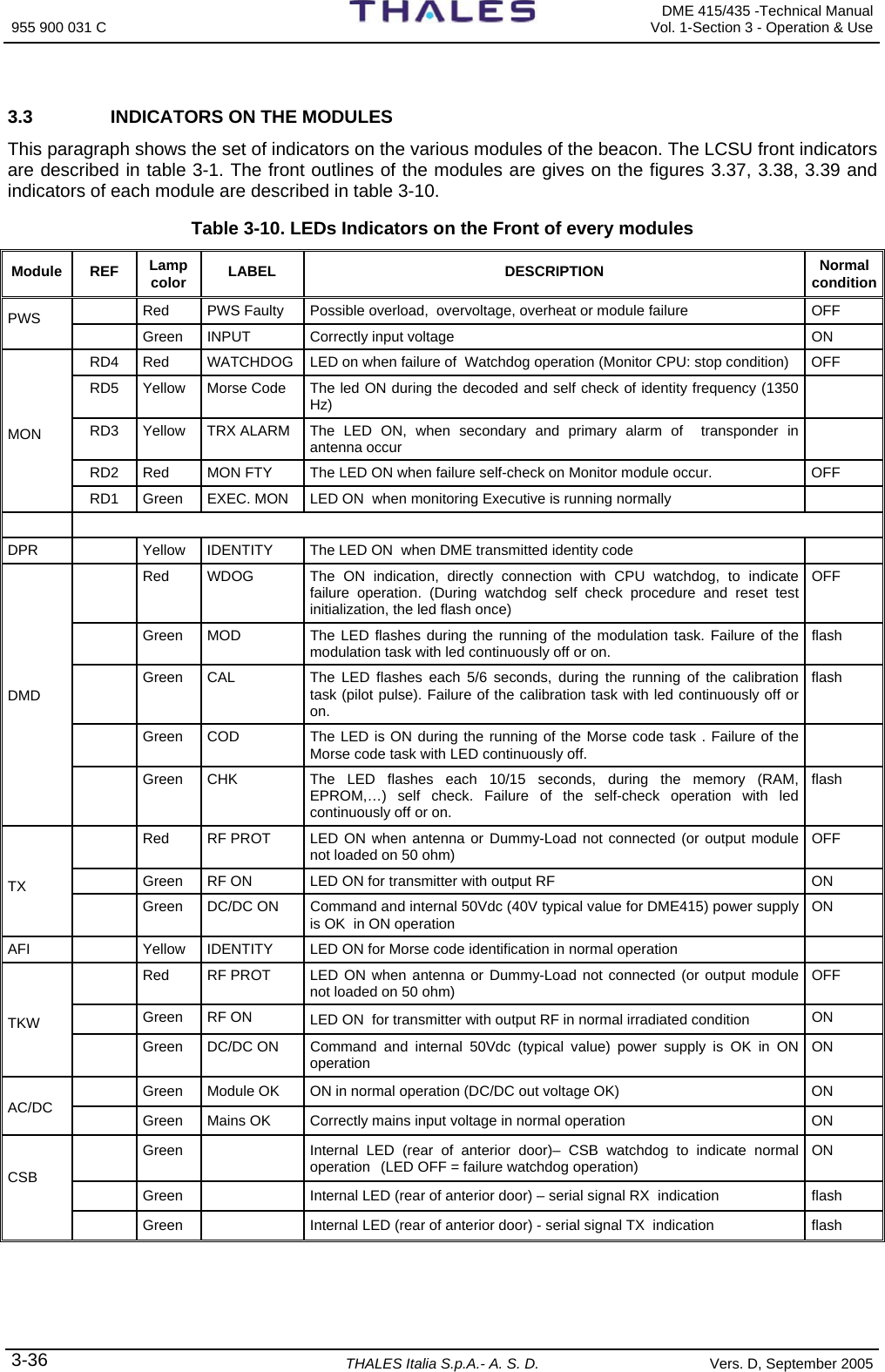
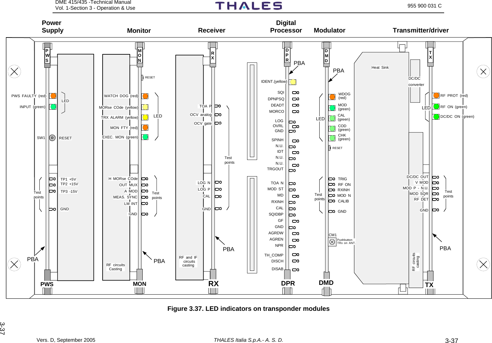
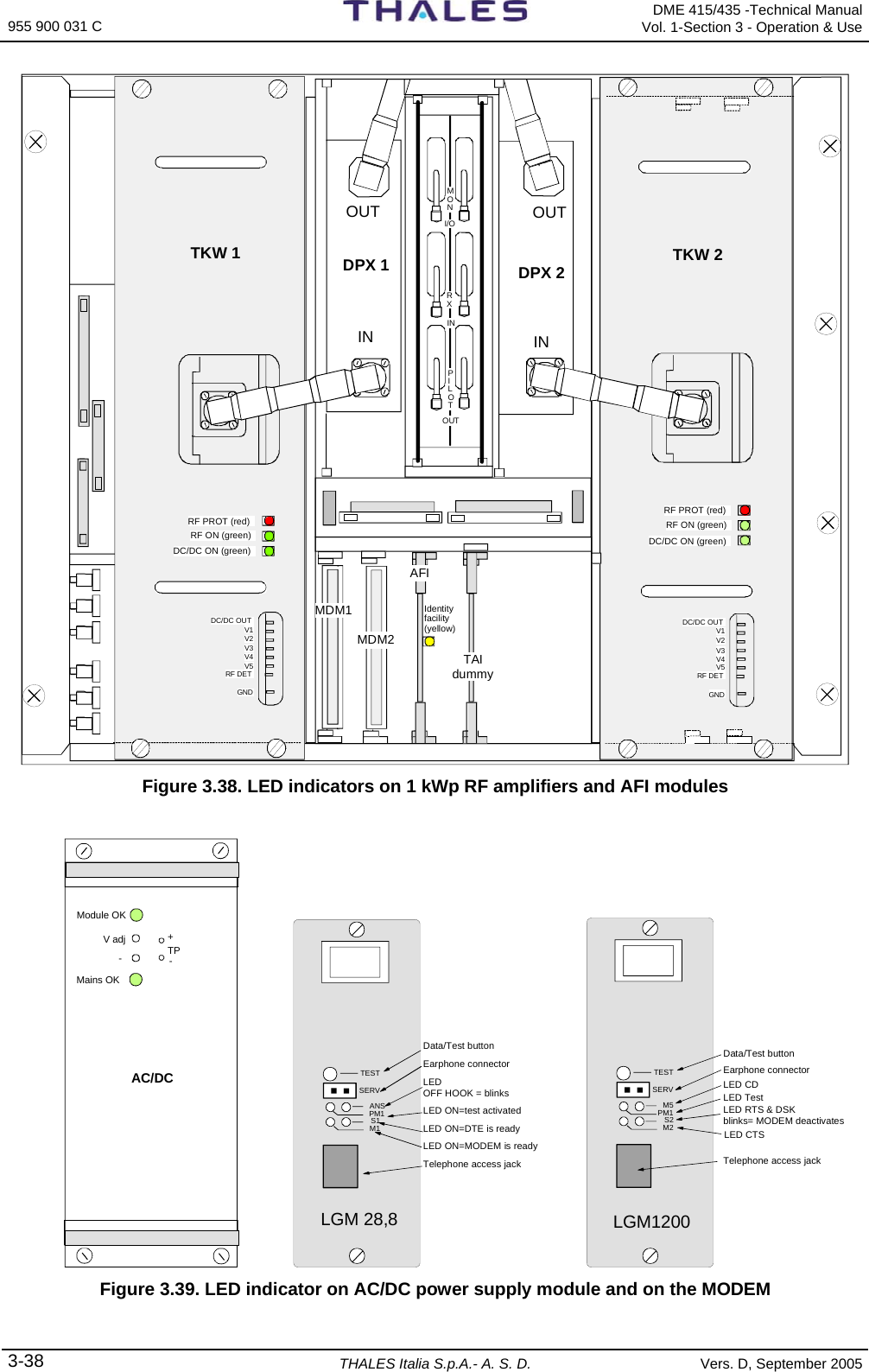
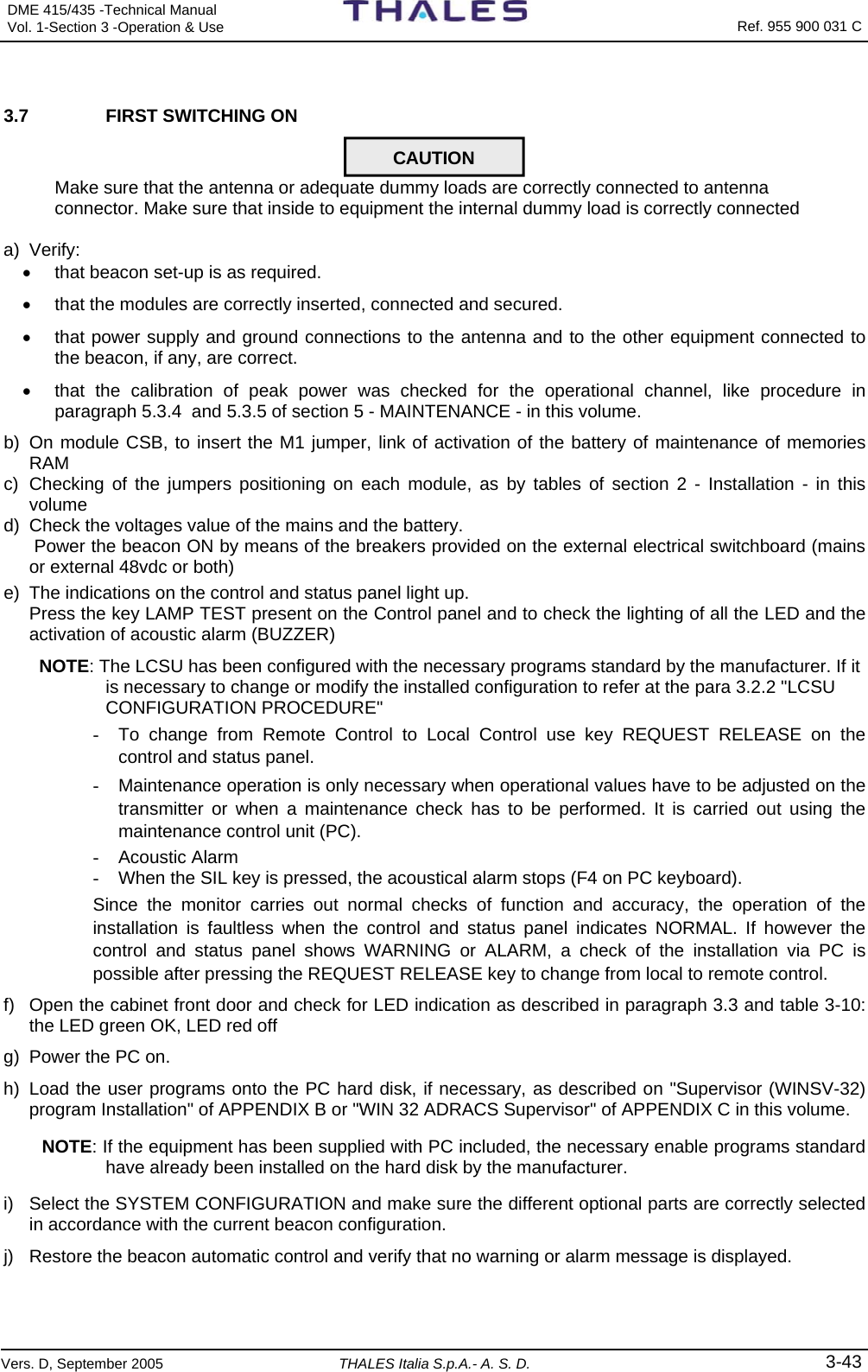
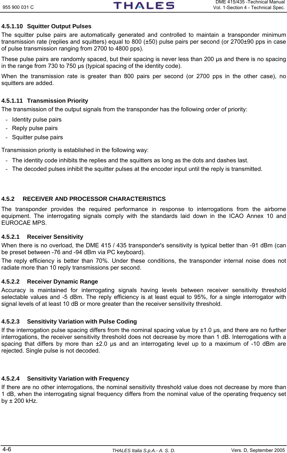
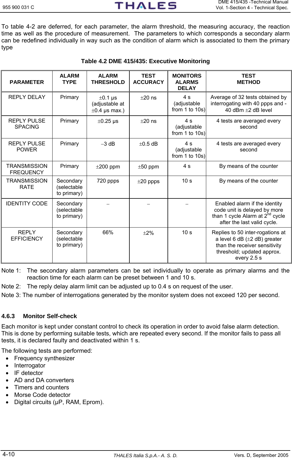
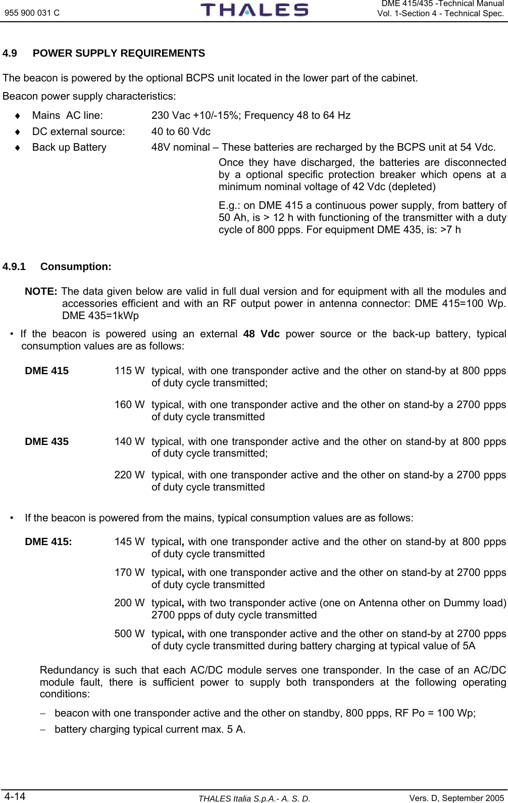
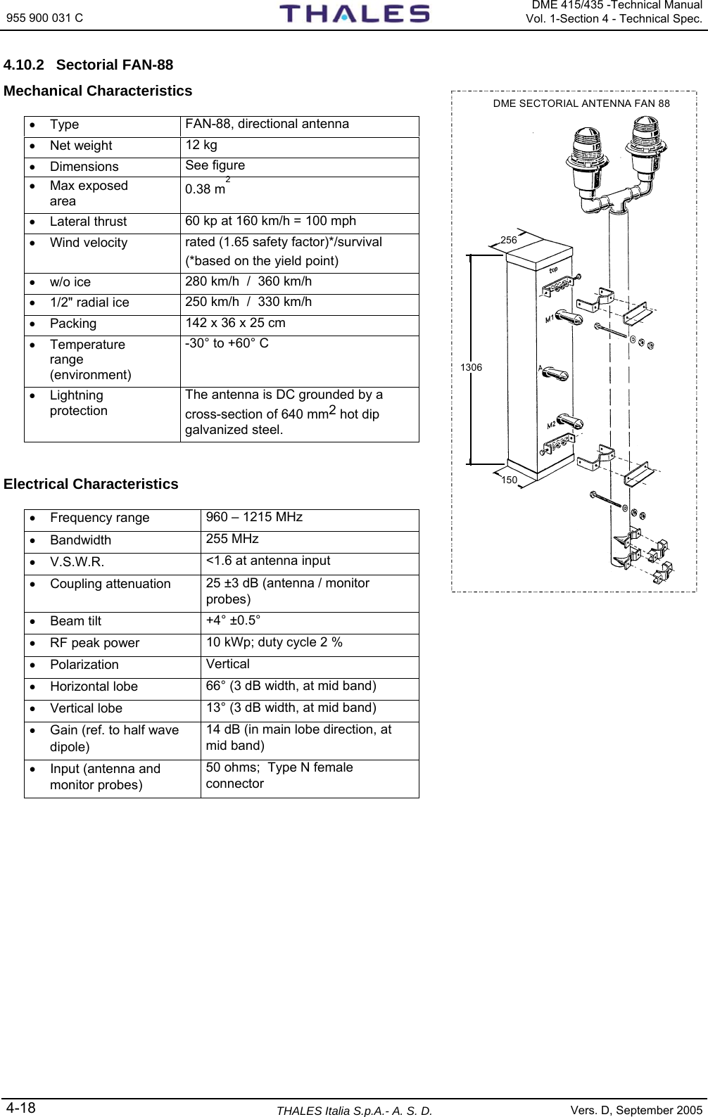
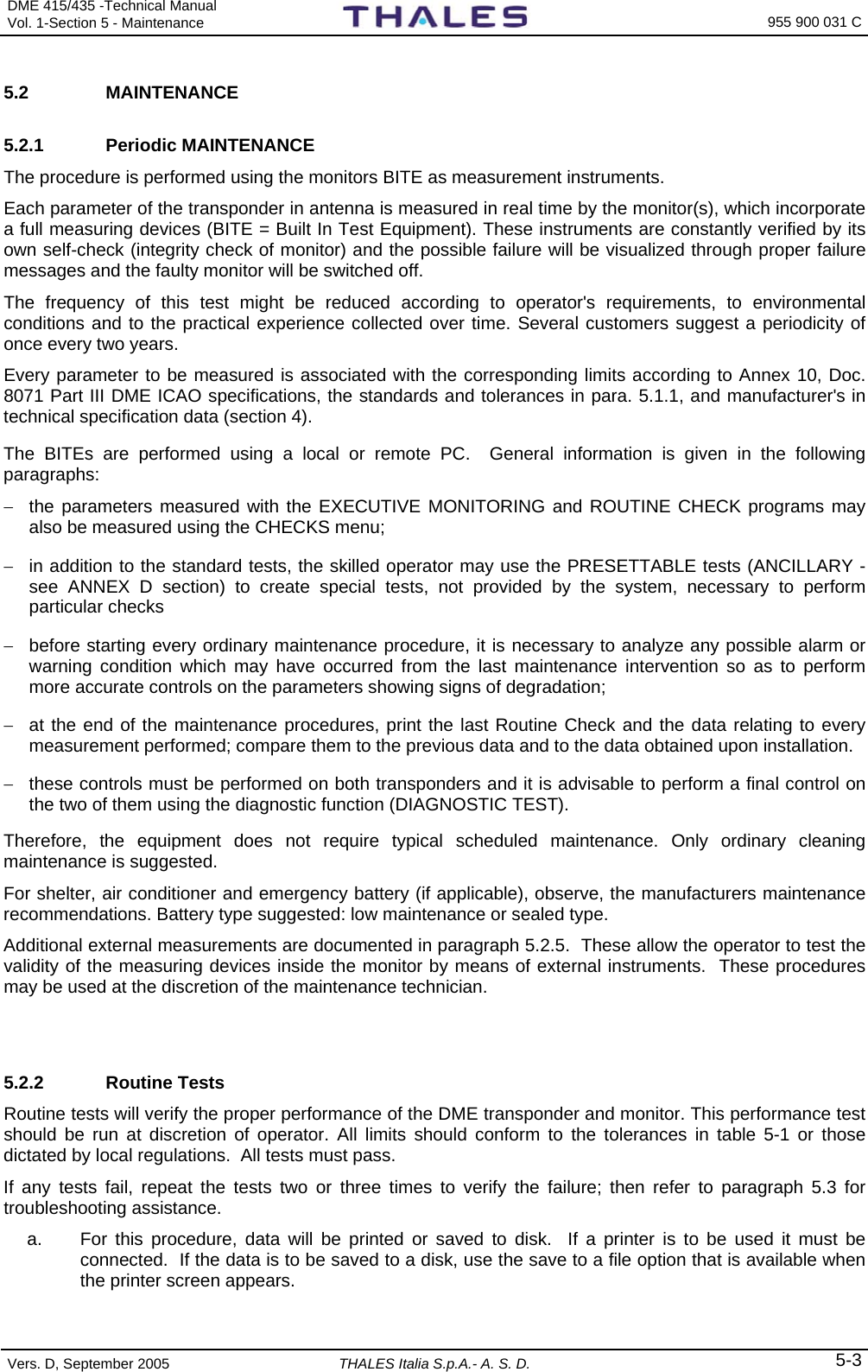
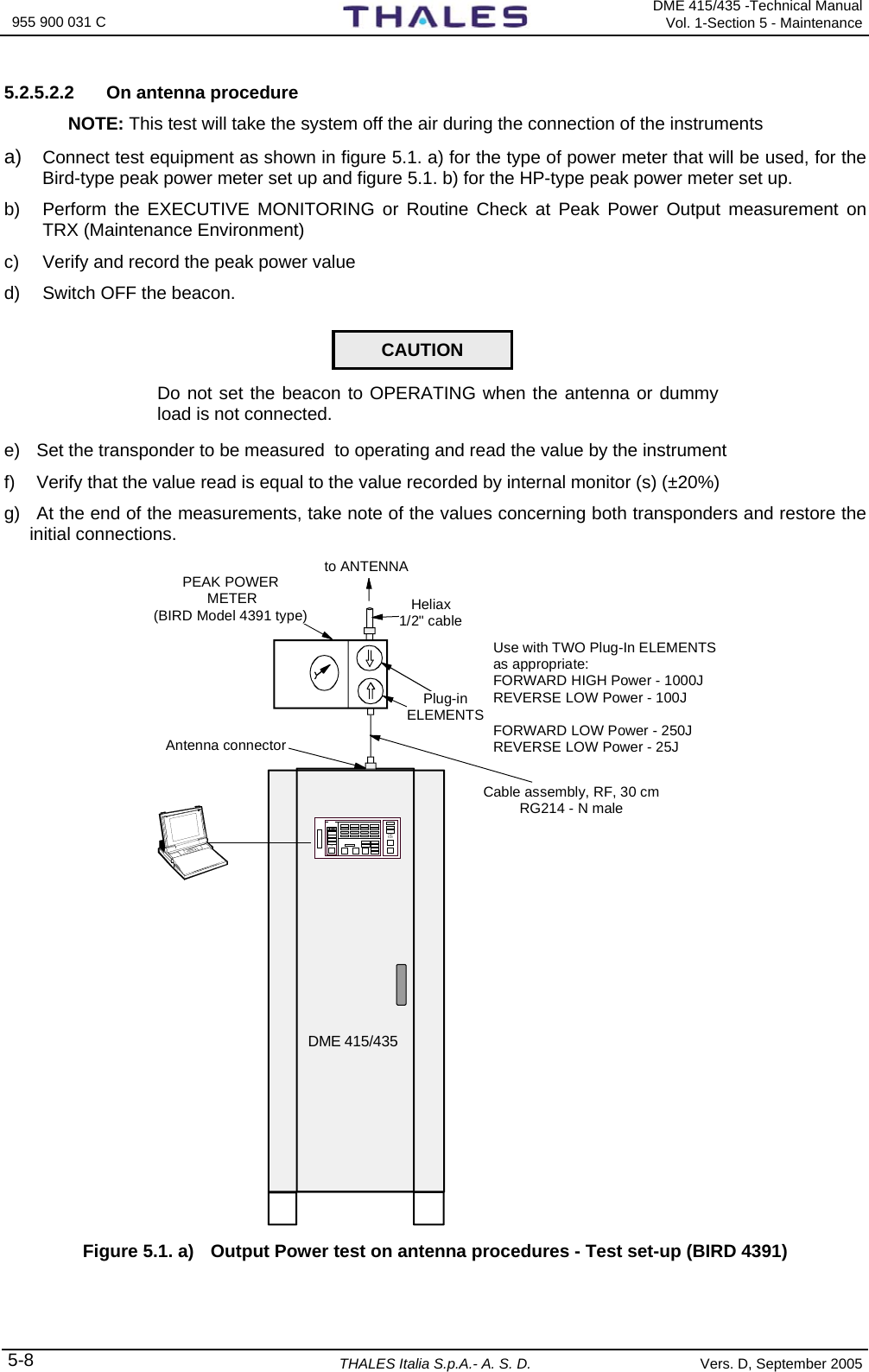
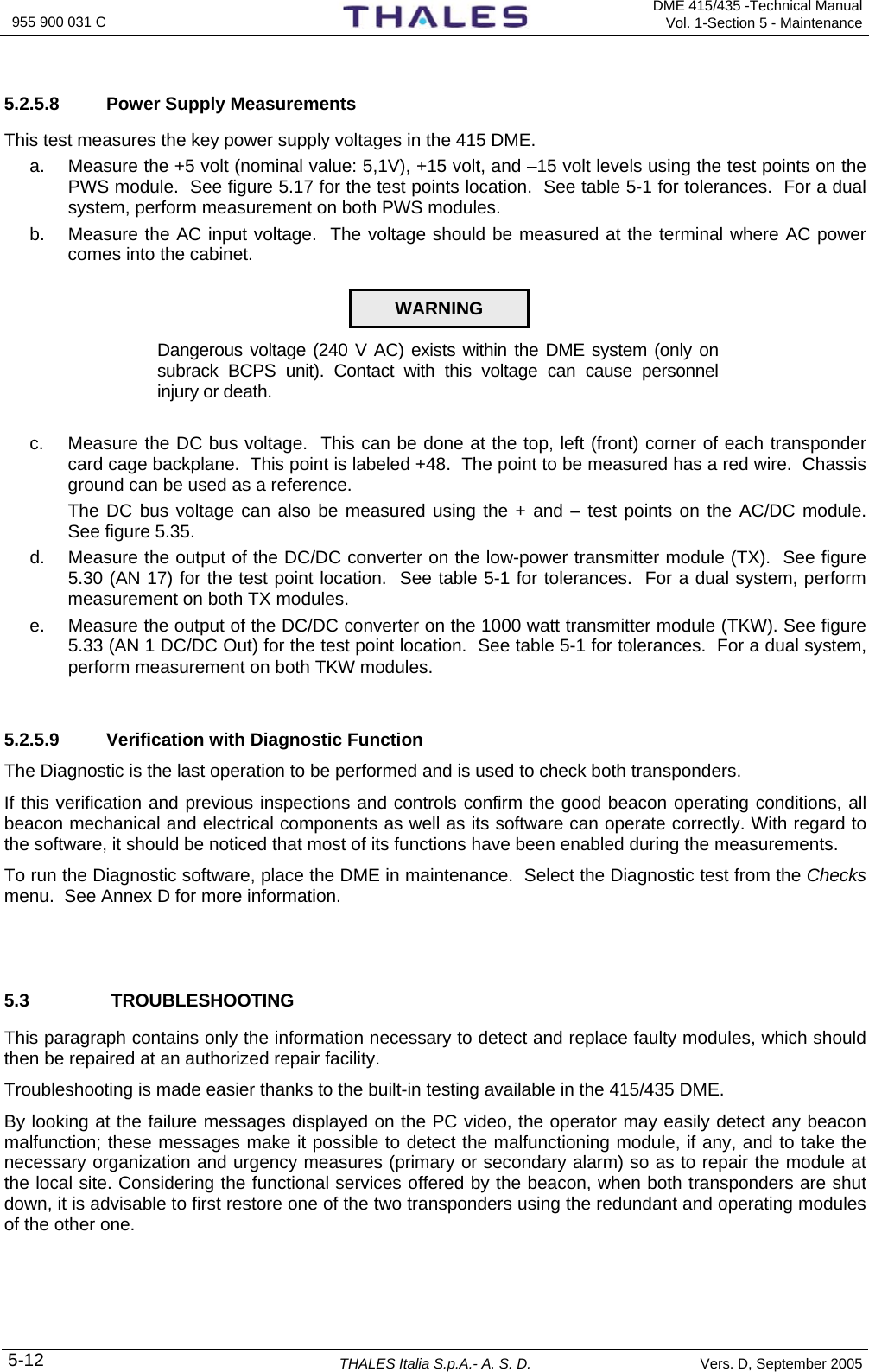
![DME 415/435 -Technical Manual Vol. 1-Section 2 - Installation 955 900 031 C Vers. D, September 2005 THALES Italia S.p.A.- A. S. D. 2-17 2.6.4.2.1 Check of the OUTPUT POWER measurement on transponder a) Preset the equipment in "Maintenance" mode (TX in STBY). Unplug the antenna cable and to connect the "peak power meter", as in fig. 2.16a, to the antenna connector. Switch to “OPERATING” mode, take notes of the reading of the power peak meter. b) Restore the connections of the antenna cables. With TX main in OPERATING and on window “EXTENDED CONFIGURATION – Mon. 1 Power Adj.” Enter, if necessary, a preset value from -100, 99, -98 ......to ..... +98,+99,+100 (Nr. 1 step by step), in order for the measurement reading on “Executive monitoring: Peak Power Output” to be the same (±2%) as the one indicated on the external “Peak Power Meter”, previously noted. c) Repeat point b) for “Mon. 2 Power Adj." on window “EXTENDED CONFIGURATION 2.6.4.2.2 Measurement calibration of the TRANSMITTED POWER (radiated) a) TX main on antenna in OPERATING. On window “EXTENDED CONFIGURATION – Monitor Cable loss” enter the value, measured or calculated, of the monitor probe cable loss (for standard cable see table in previous para. 2.6.4.1) b) On “EXTENDED CONFIGURATION – Monitor Probe Coupling” enter the value of the coupler at the operating frequency, a detail that is pointed out on the antenna features. For the model FAN 96 and FAN 88 the coupling values of the probes are shown on a table enclosed to the package of the antenna (for antenna FAN 96: typical value 20dB ± 3dB) c) On “EXTENDED CONFIGURATION – Antenna cable loss” enter the value, measured or calculated, of the antenna cable loss (for standard cable see table in previous para. 2.6.4.1) d) The measure indicated in “Transmitted Power”, in theory, should be: [“Peak Power Output” – Antenna cable loss] in Watt Some significant power ratios and loss percentage are calculated as per the following table 2-4 : Table 2-4 - Loss of STD coax cables Ant. cable loss: dB Ratio Loss % -3 0,5 50 -2 0,63 37 -1,5 0,708 29,2 -1 0,78 22 -0,5 0,89 11 -0,1 0,9772 2,28 Example: with STD cable (25m – LCF ½”) the reading in “Transmitted Power” must be: 1) for DME 415 with 110 W in Peak Power Output: 110 – (110 * 0,347) = 71,83 W 2) for DME 435 with 1050 W in Peak Power Output: 1050 – (1050 * 0,347) = 685.6 W e) if the reading in “Transmitted Power” is over ± 2% compared to the value mentioned in point d), vary, step by 0,1dB step , the data on window “EXTENDED CONFIGURATION – Monitor Probe Coupling” (or in “Monitor cable loss”) up to the limit of ± 2%. NOTE 1: The sum of the values in dB [Monitor Cable Loss + Antenna Probe Coupling + Antenna Cable Loss] must be >20 dB and <33 dB, otherwise the data will refused. NOTE 2: Values in “Transmitted Power” of each monitor can be adjusted within ±10%. Difference of measure of the values in "Transmitted Power" between the two monitors due to different attenuations of the coaxial cables, couplers and internal coax cabling, can be corrected with the trimmer P6 mounted on module MON (shown in fig. 2.17), in order for each monitor to read measurements that are as equivalent as possible.](https://usermanual.wiki/Thales-ATM/435.USERS-MANUAL-2/User-Guide-857503-Page-21.png)
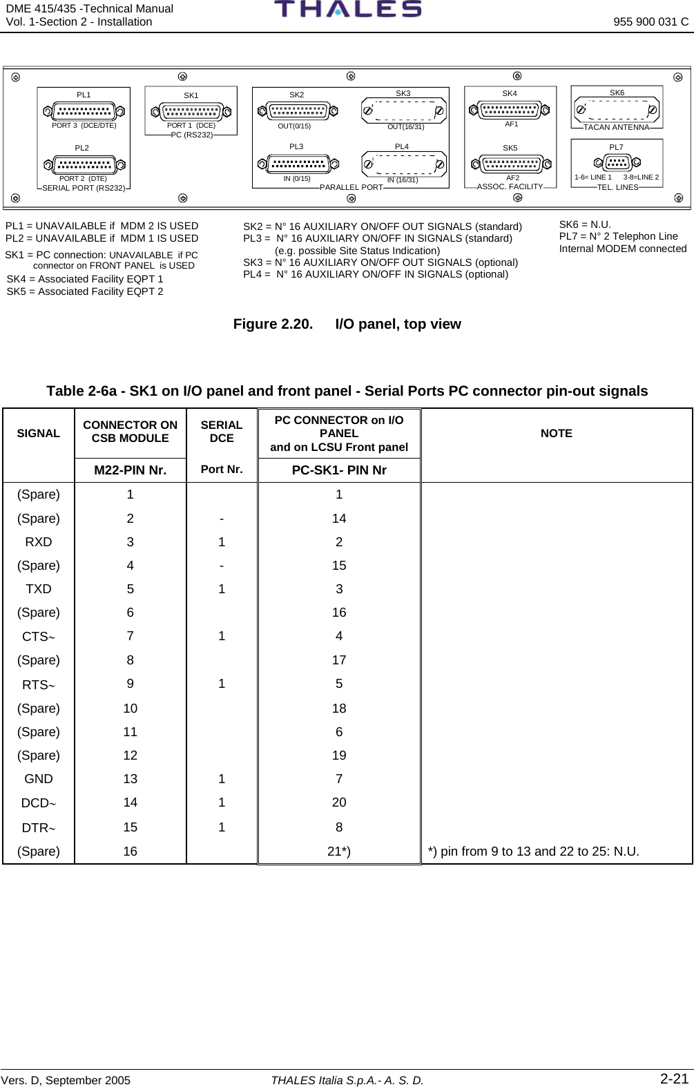
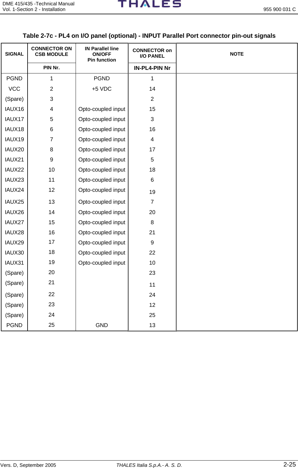
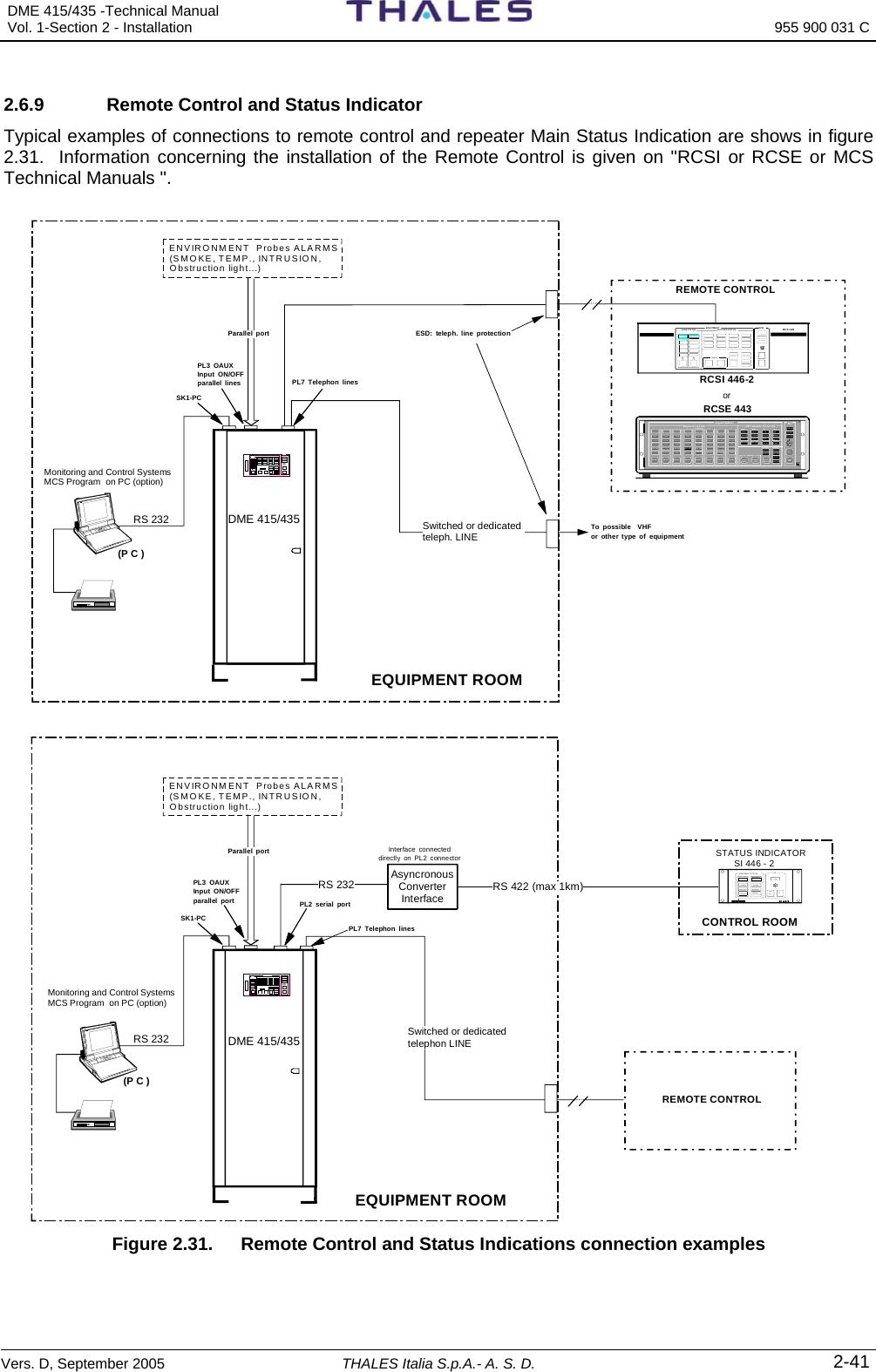
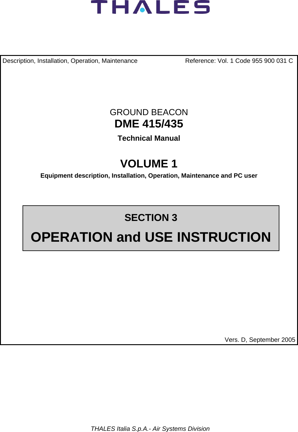


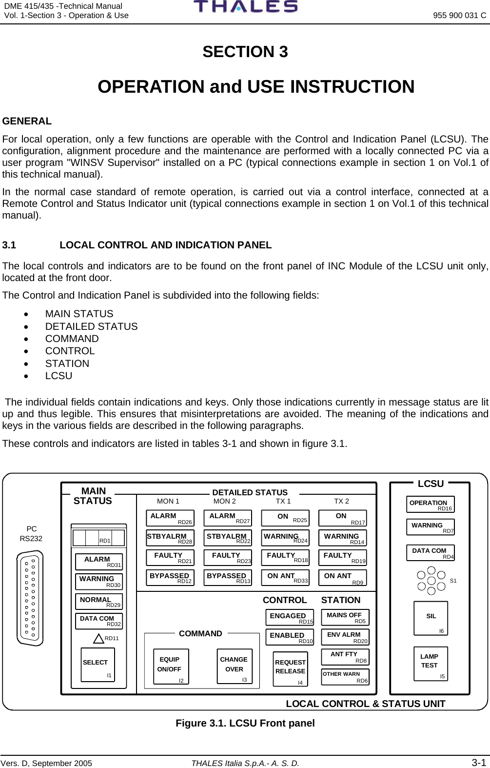
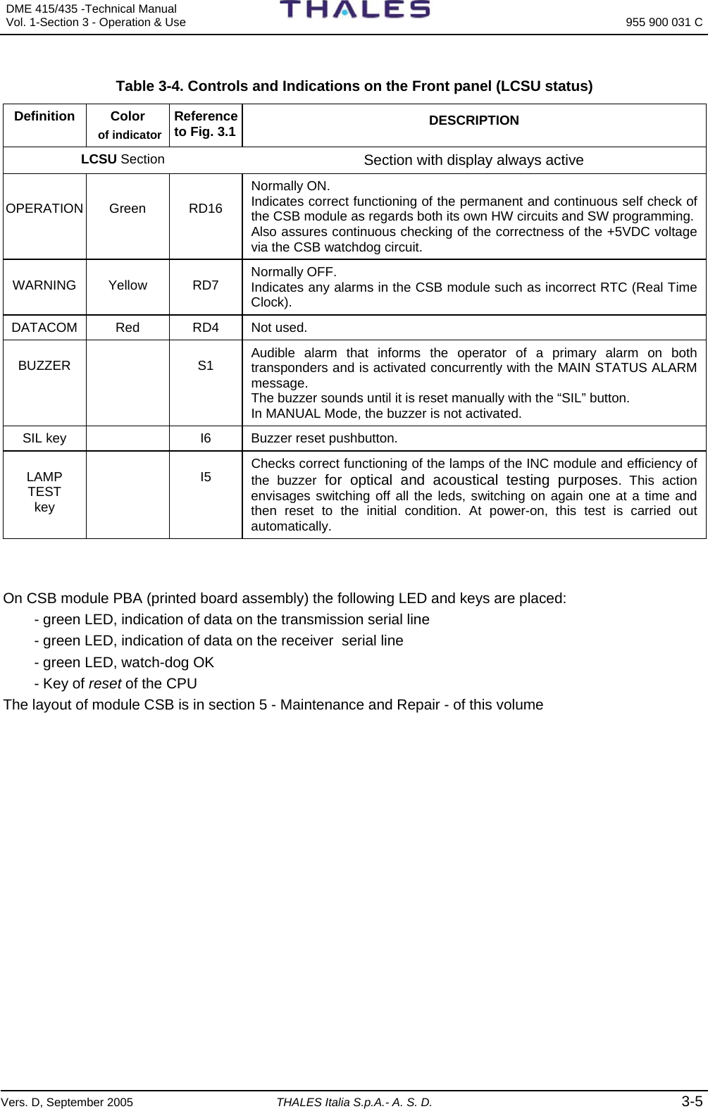
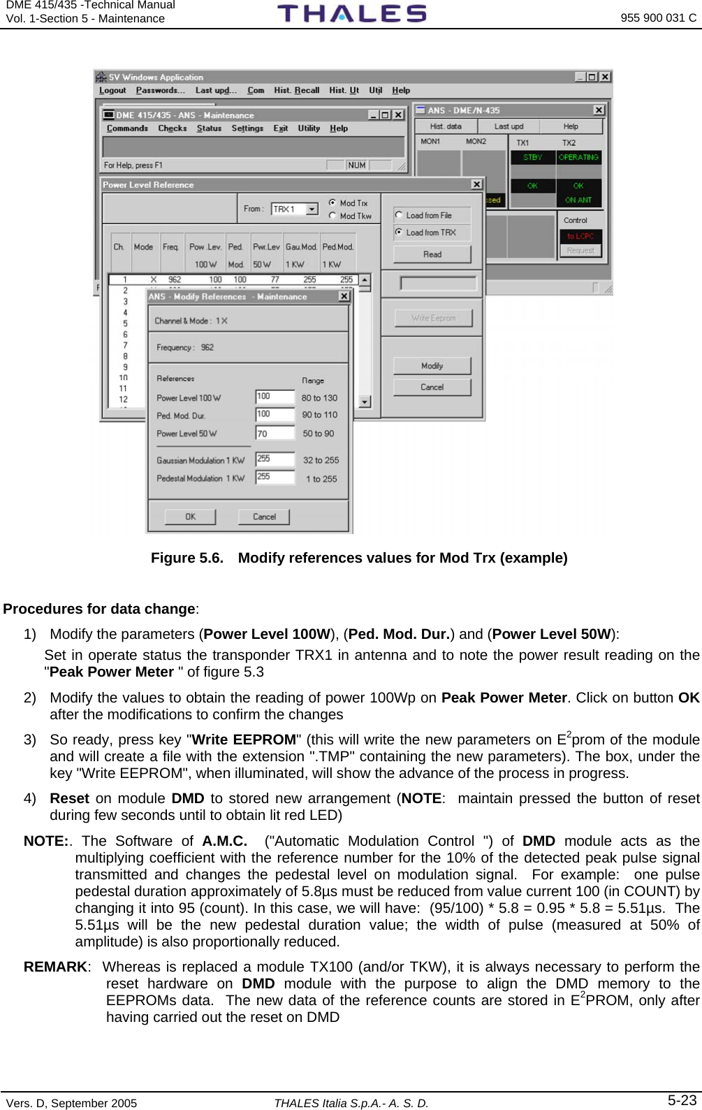
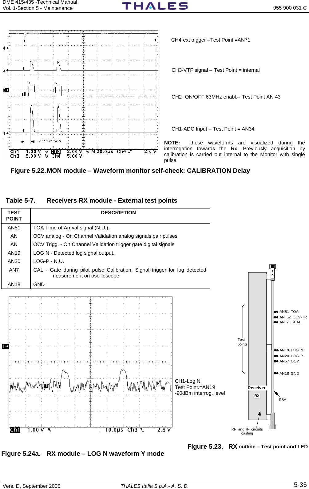
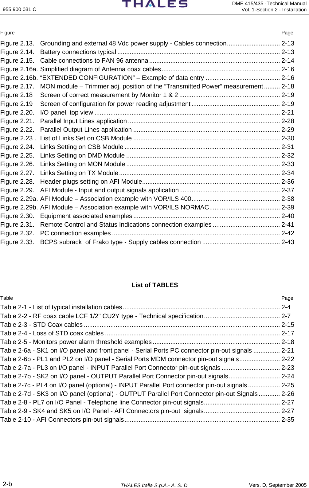
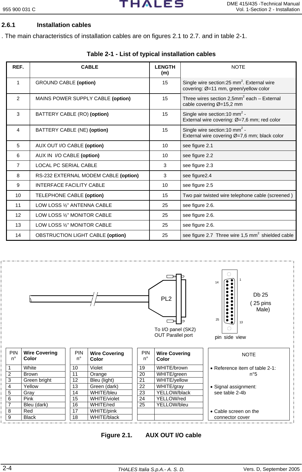
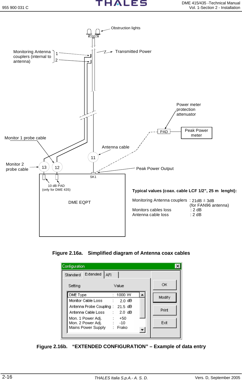
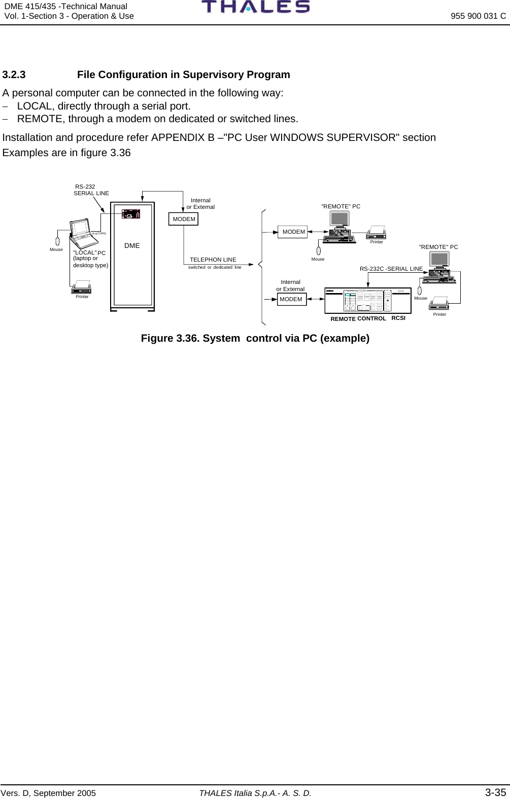
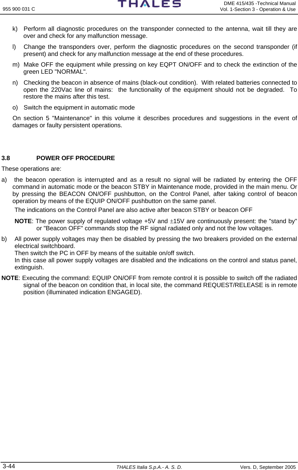
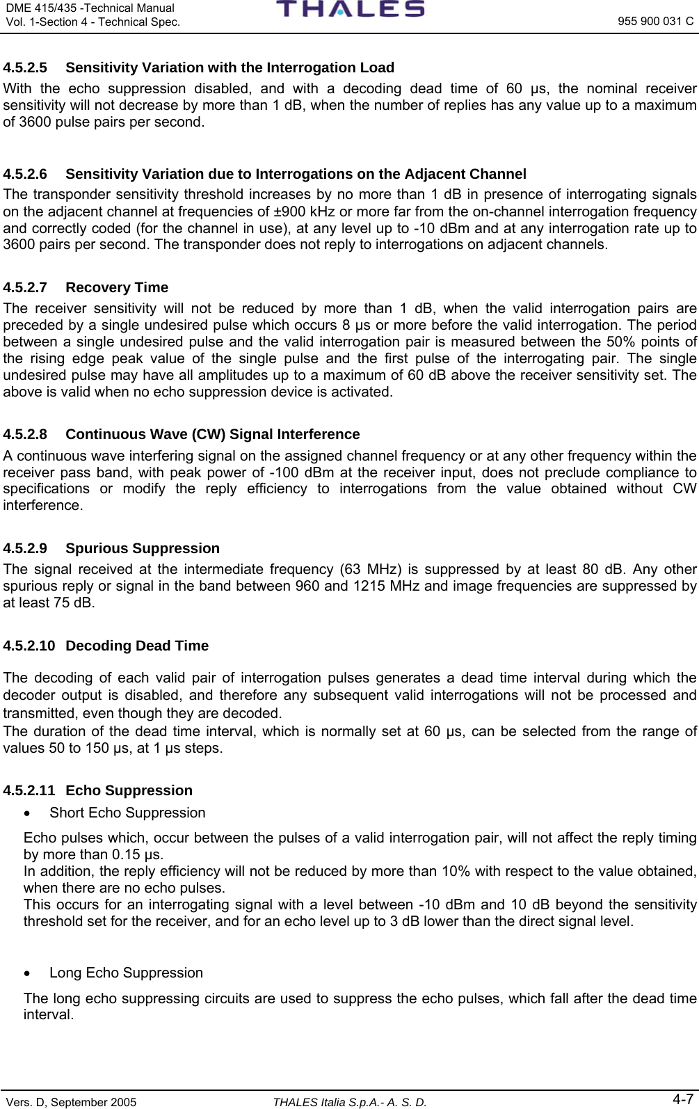
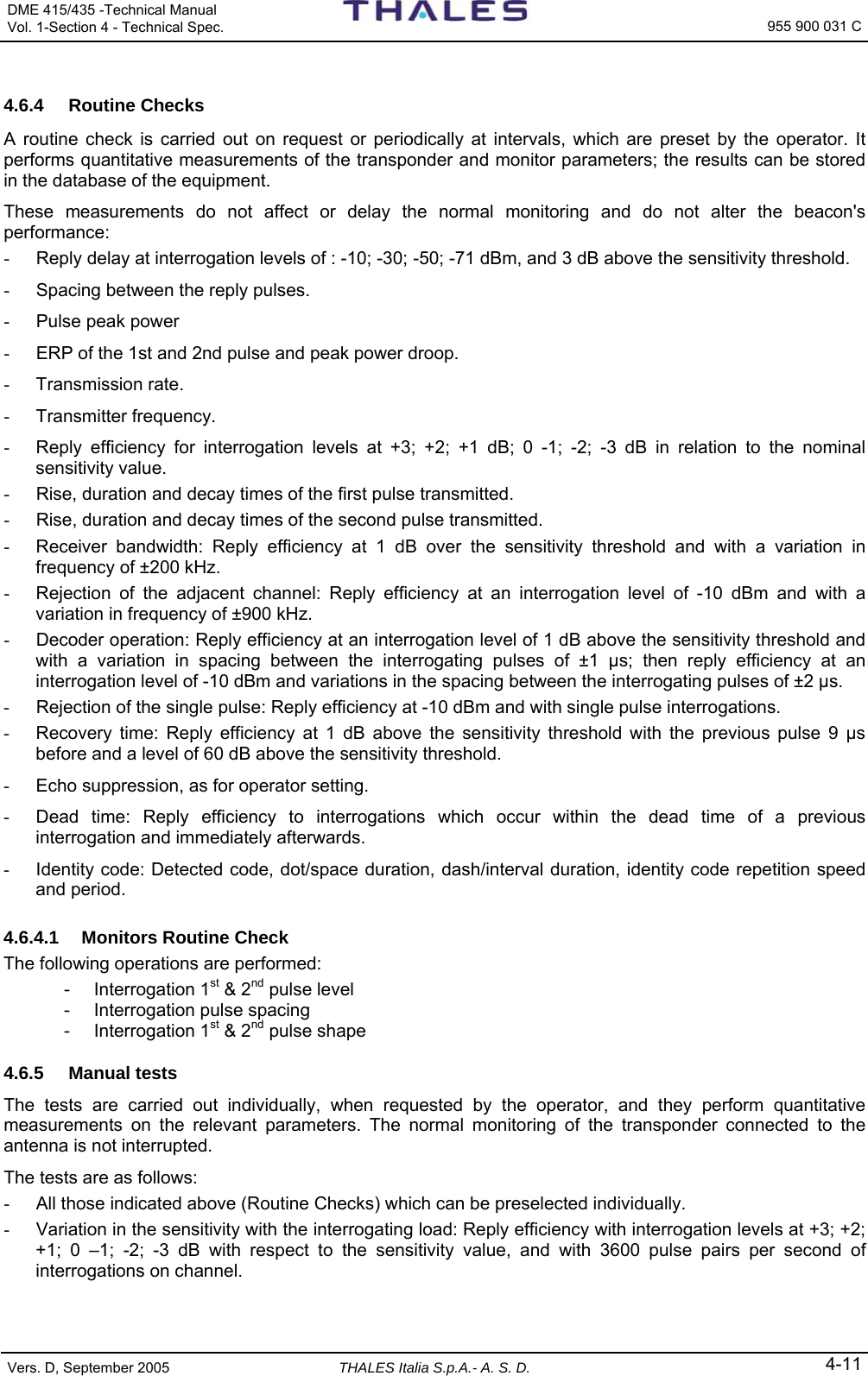
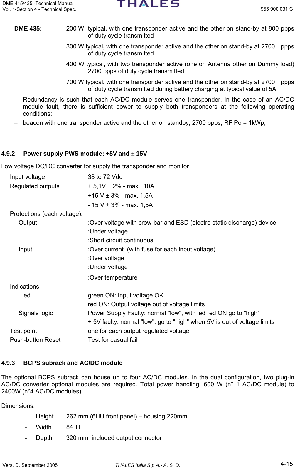
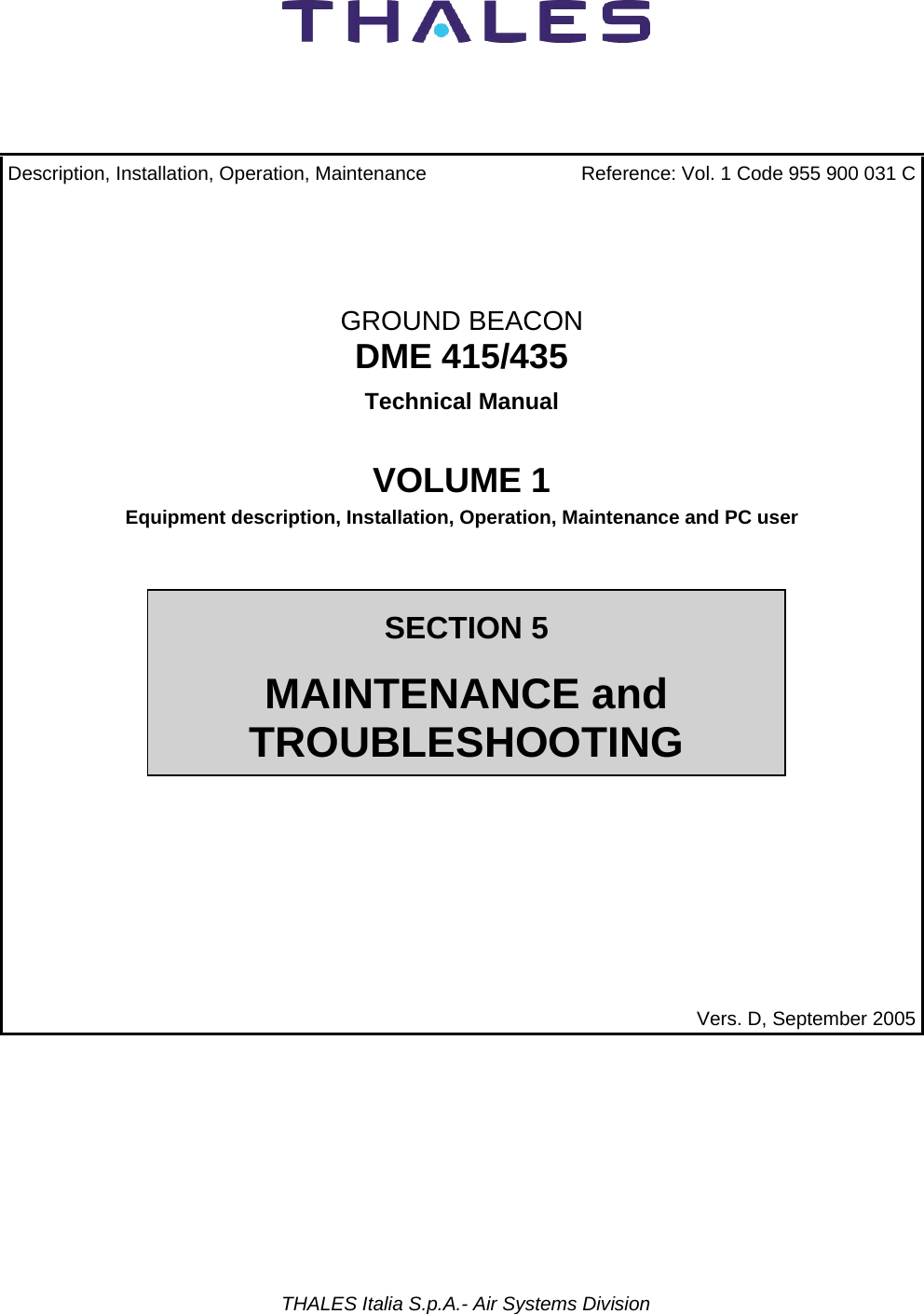
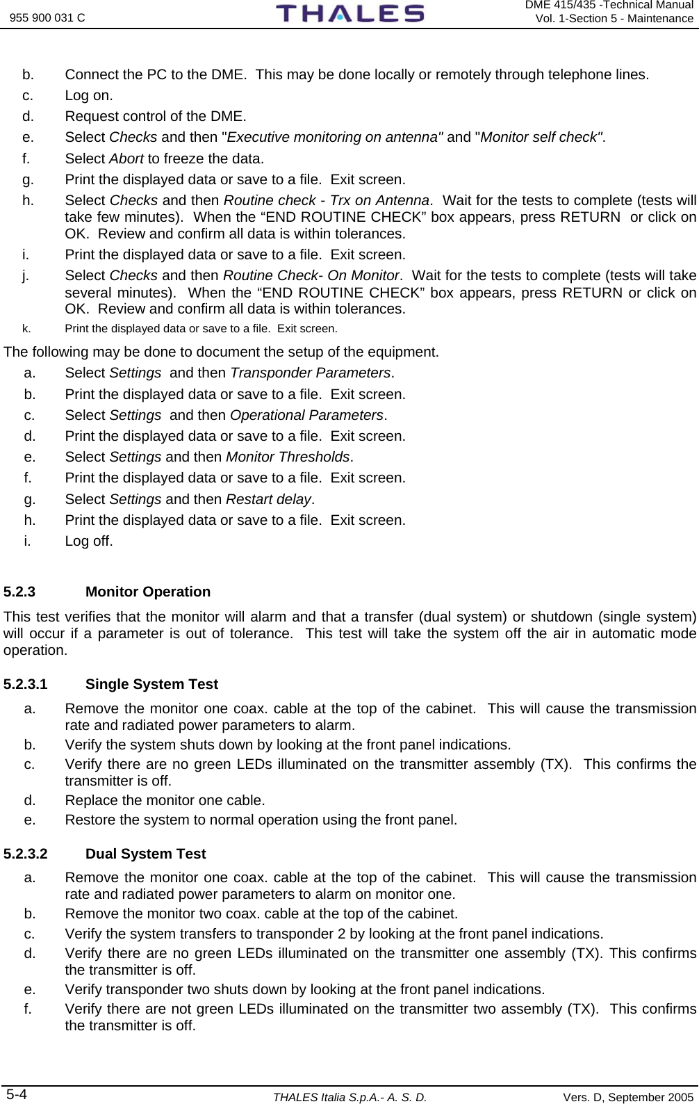
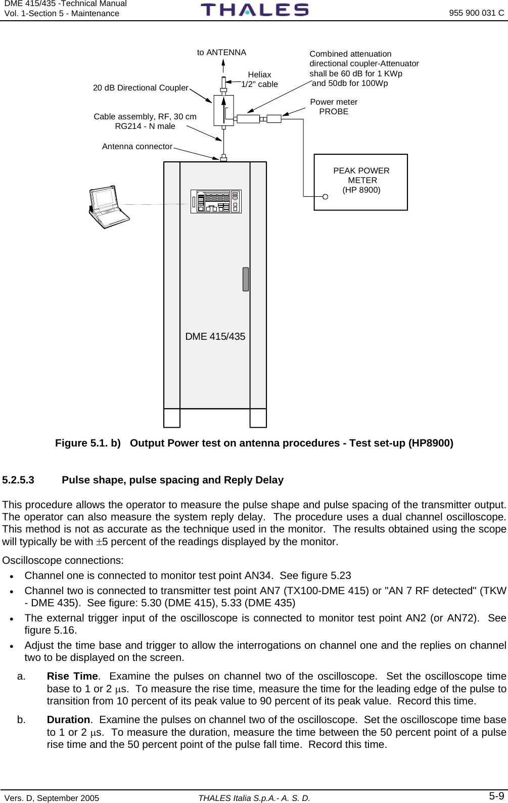
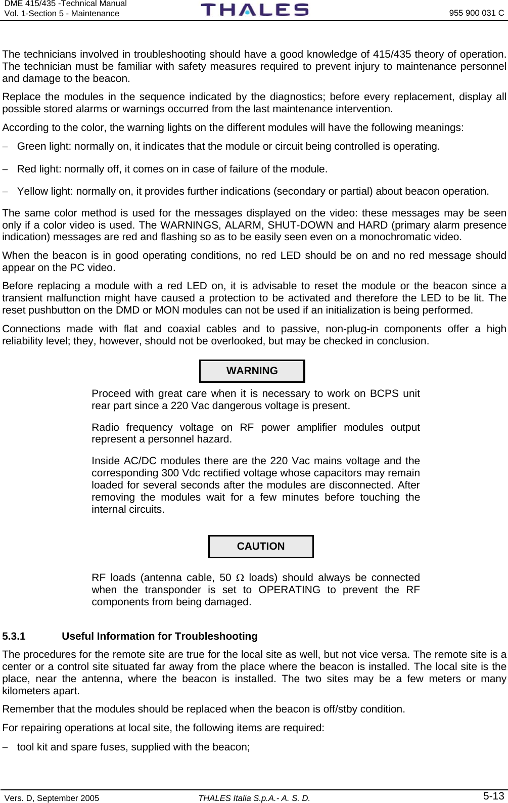
![DME 415/435 -Technical Manual Vol. 1-Section 3 - Operation & Use 955 900 031 C Vers. D, September 2005 THALES Italia S.p.A.- A. S. D. 3-7 3.2.2 LCSU CONFIGURATION PROCEDURE To modify the LCSU configuration parameters connect a PC to connector SK1 on the I/O panel (or directly to the front panel of the LCSU unit named PC RS232) This paragraph describes some video page examples that are displayed during the configuration procedure. The notes concerning some video pages are remarks and memorandum to be followed when loading the configuration procedure. The LCSU configuration procedure can also be activated when the DME is operating, since the beacon is managed by a specific program. To load the program, proceed as follows: − run the “EMUL.exe” program from the PC; − press the "I1" RESET push-button on the PBA of CSB module (reached from the back of the equipment front door); − when the starting video page is displayed, press the keyboard space bar at least three times within a few seconds to access the configuration mode; − if access is not obtained with the first configuration video page, repeat the RESET operation; − perform the configuration procedure following the instructions displayed in the menu; − after configuration, save the variations in EEPROM; it is suggested to save the new data on a back-up diskette. − Before running the supervisor program change the parameters in the config.ini file according to LCSU configuration. 3.2.2.1 Main Menu Figure 3.2 shows the main video page of the configuration program. Besides the options indicated, it is also possible to return to the previous menu by pressing the ESC key. LCSU Maintenance Program MAIN MENU [1] System Overview [2] LCSU Configuration [3] Hardware test [0] END Select: F1 - Import Data F2 - Export Data F5 - Clear Video F10 - Quit Figure 3.2. Main Menu If, when starting up the program, an EEPROM failure is detected (faulty or containing data no longer valid), the following message is displayed at the bottom of the video page: Invalid configuration data, press a key to load default parameters. NOTE: F1, F2, F5, F10 are key of PC keyboard - ESC = previous menu](https://usermanual.wiki/Thales-ATM/435.USERS-MANUAL-2/User-Guide-857503-Page-61.png)
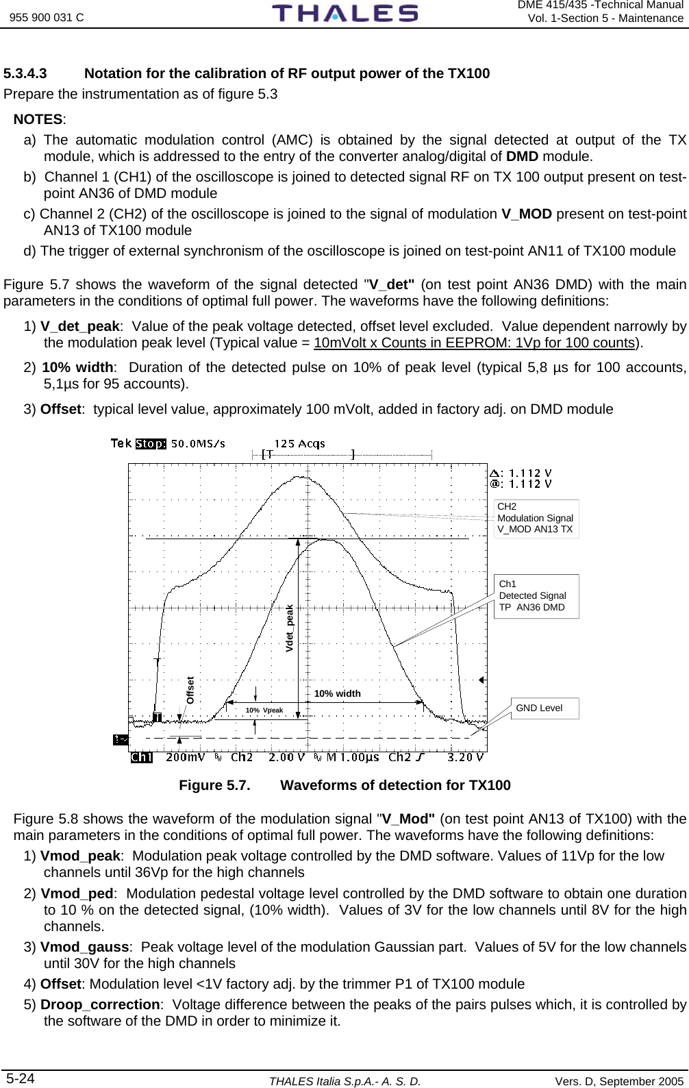
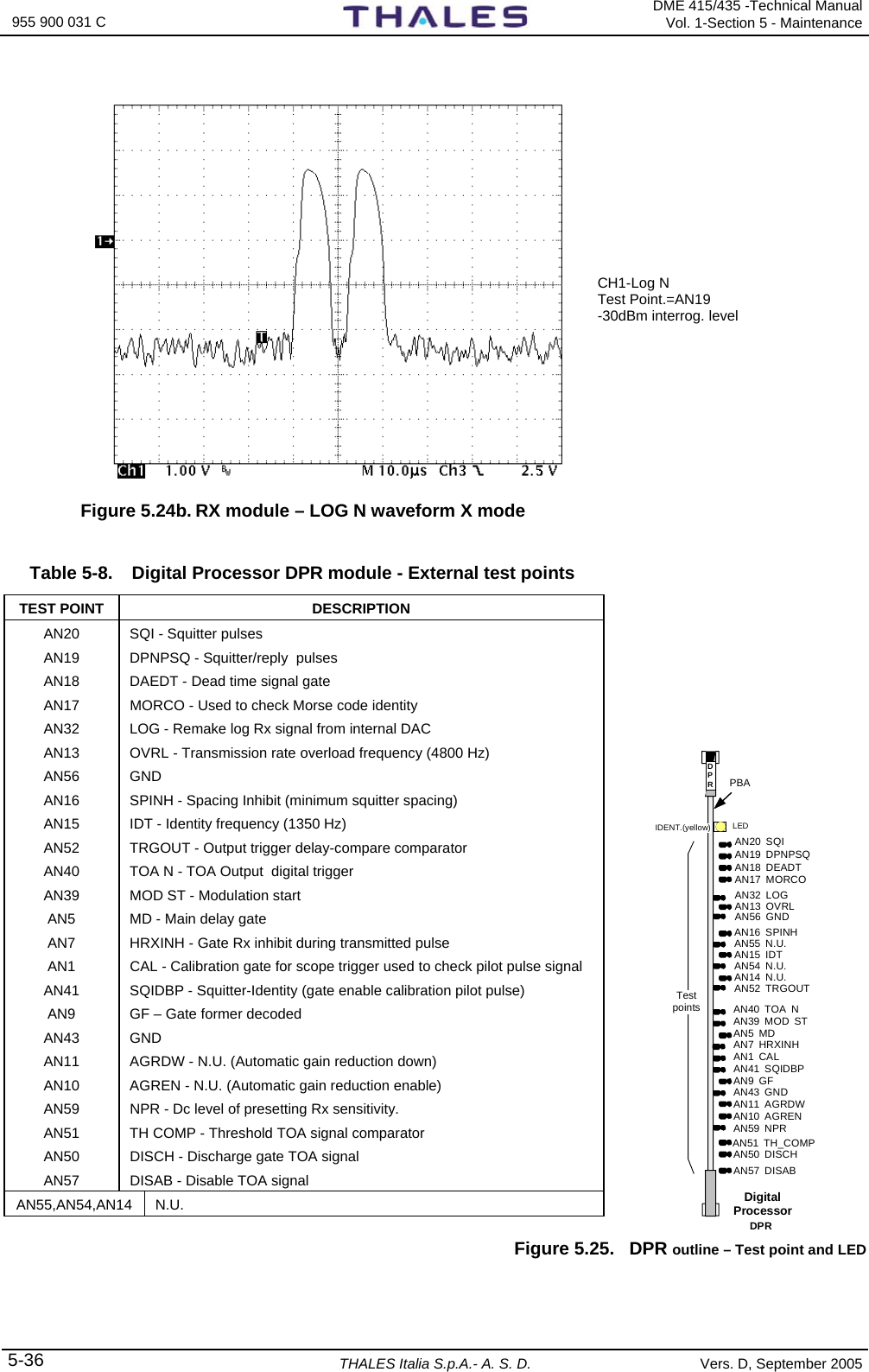
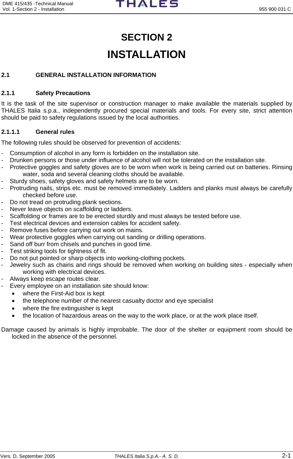
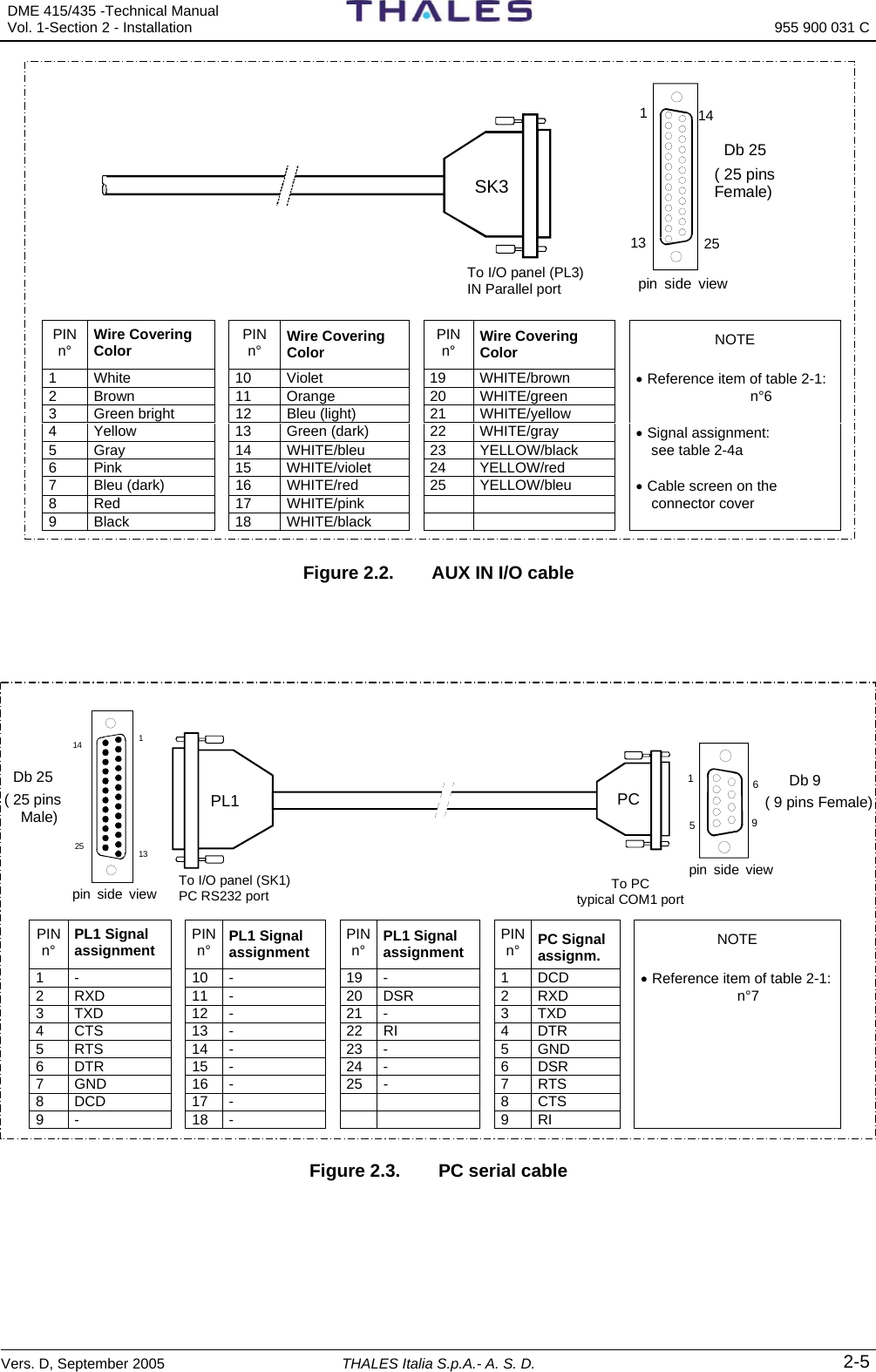
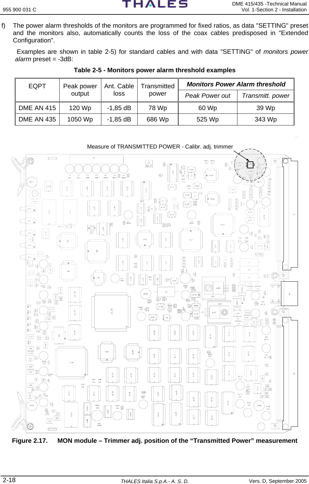
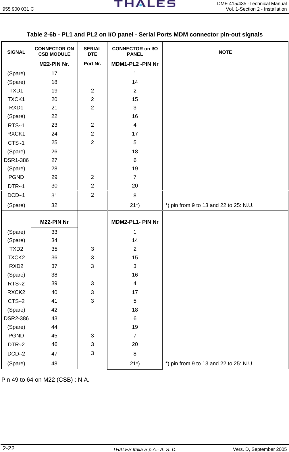
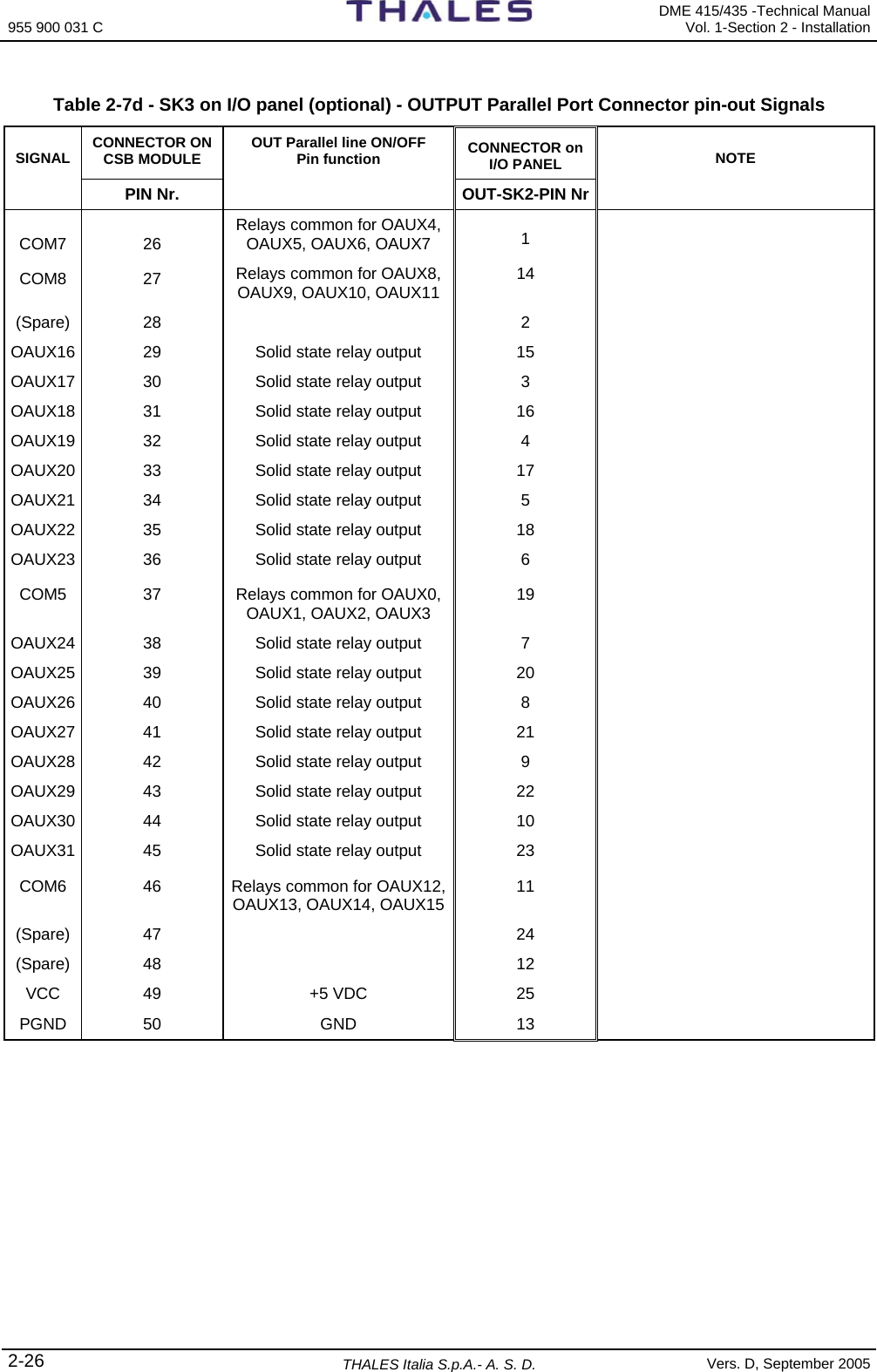
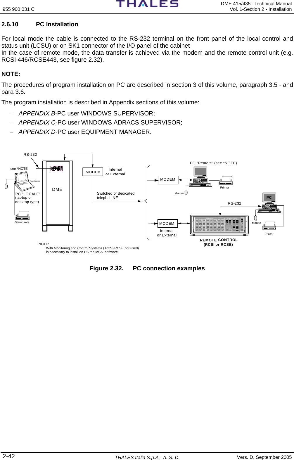
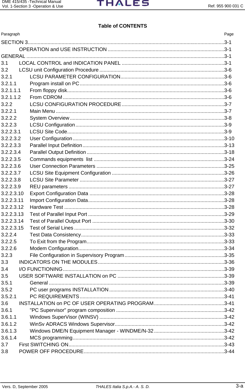
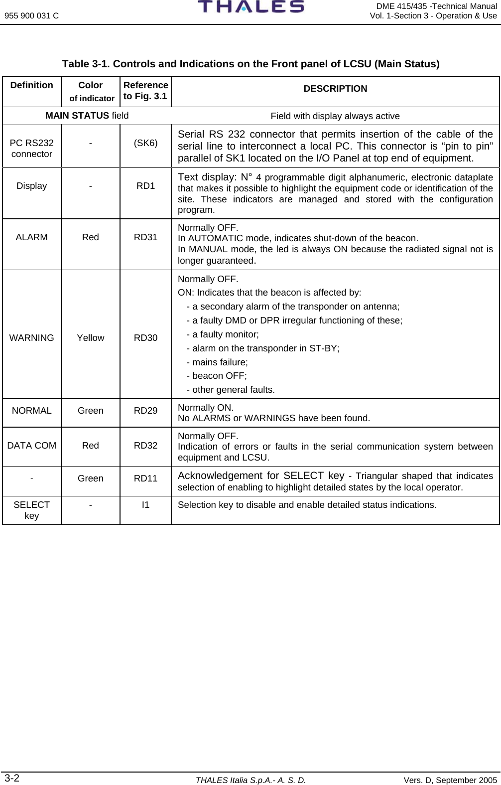
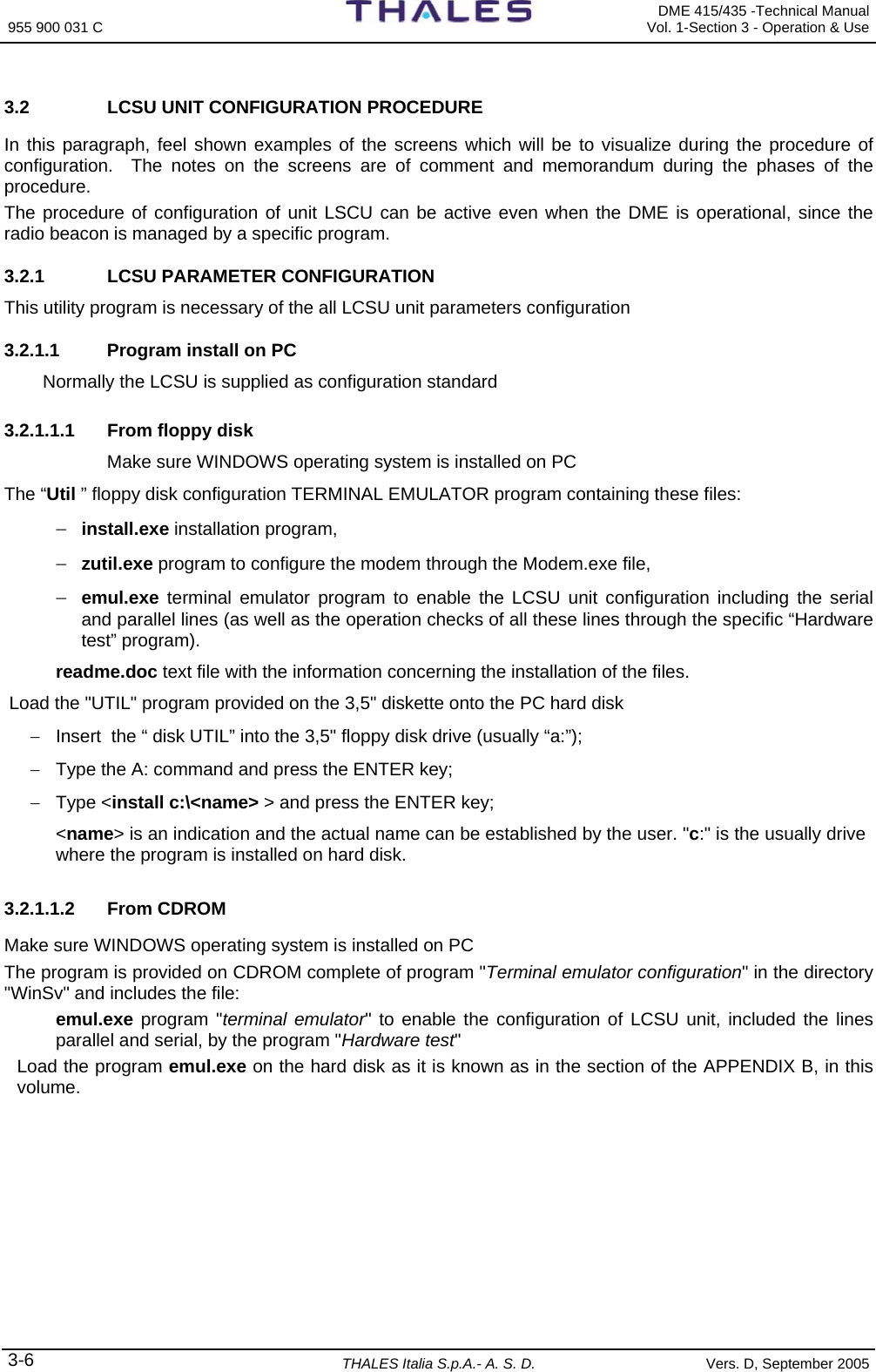
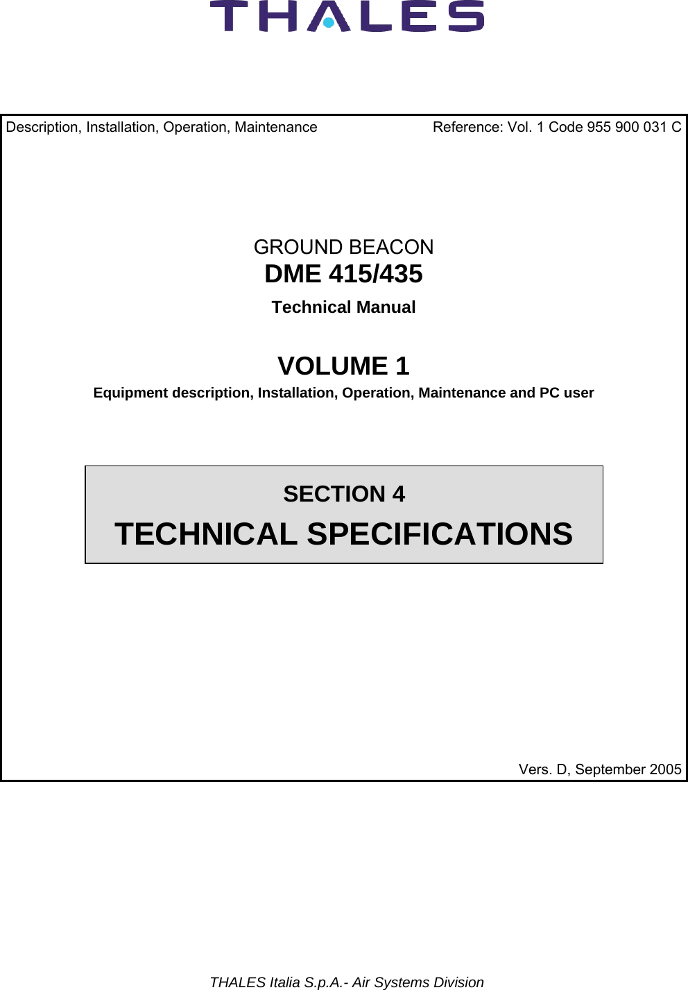
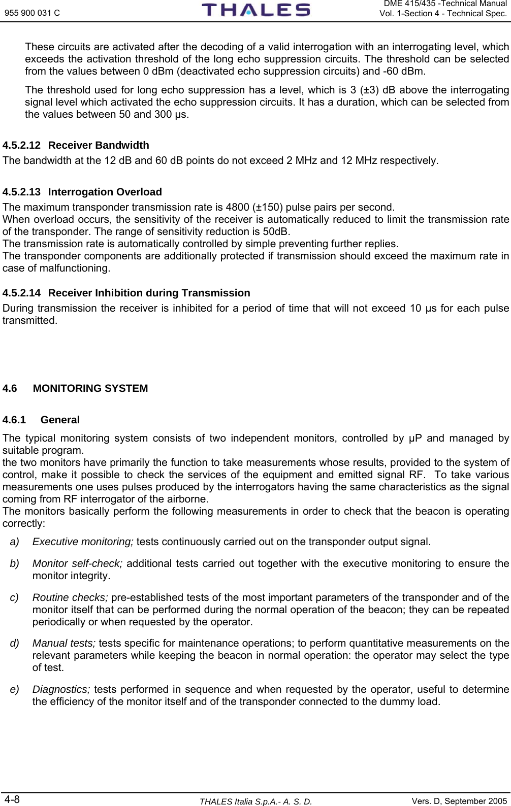
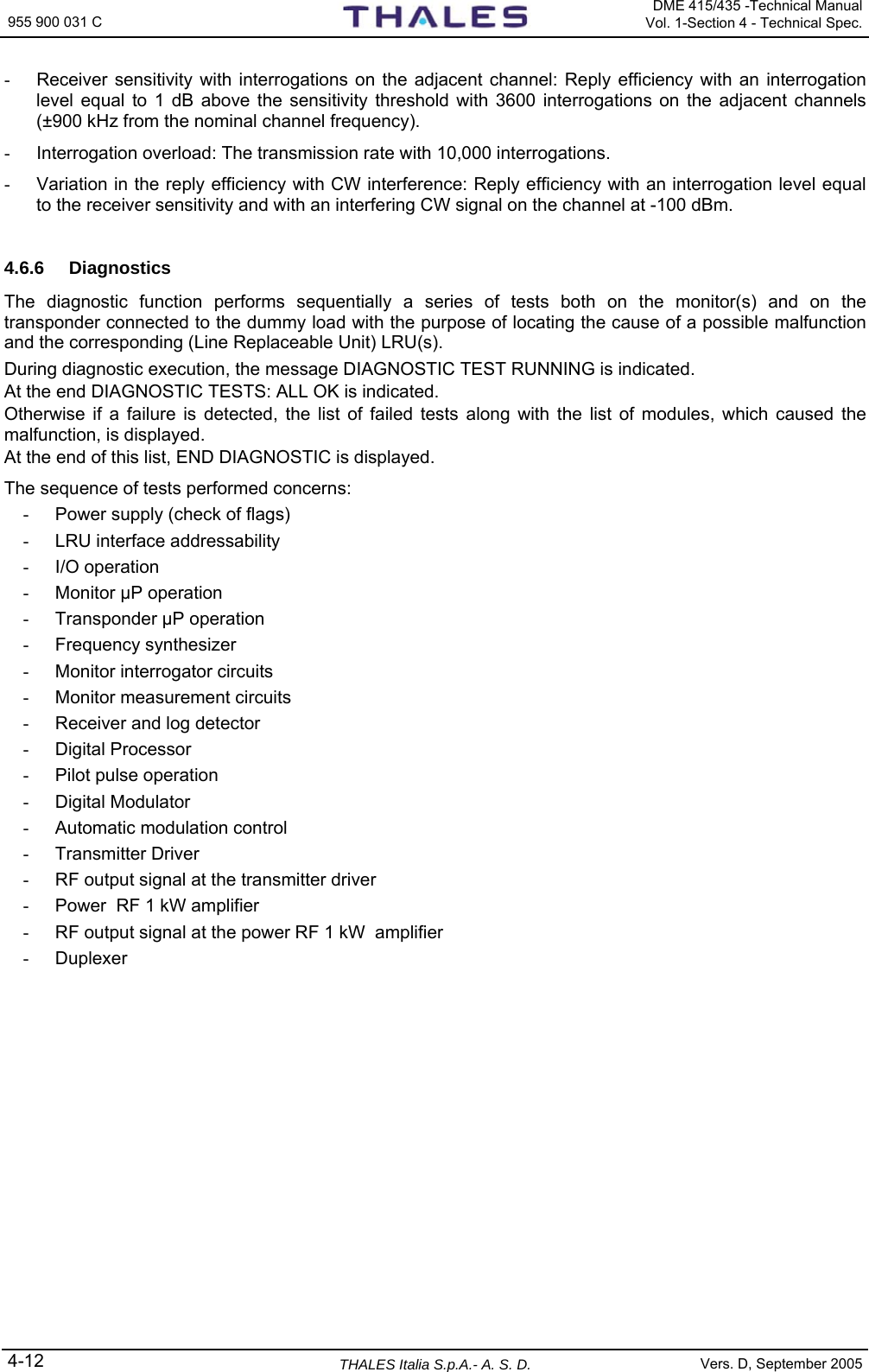
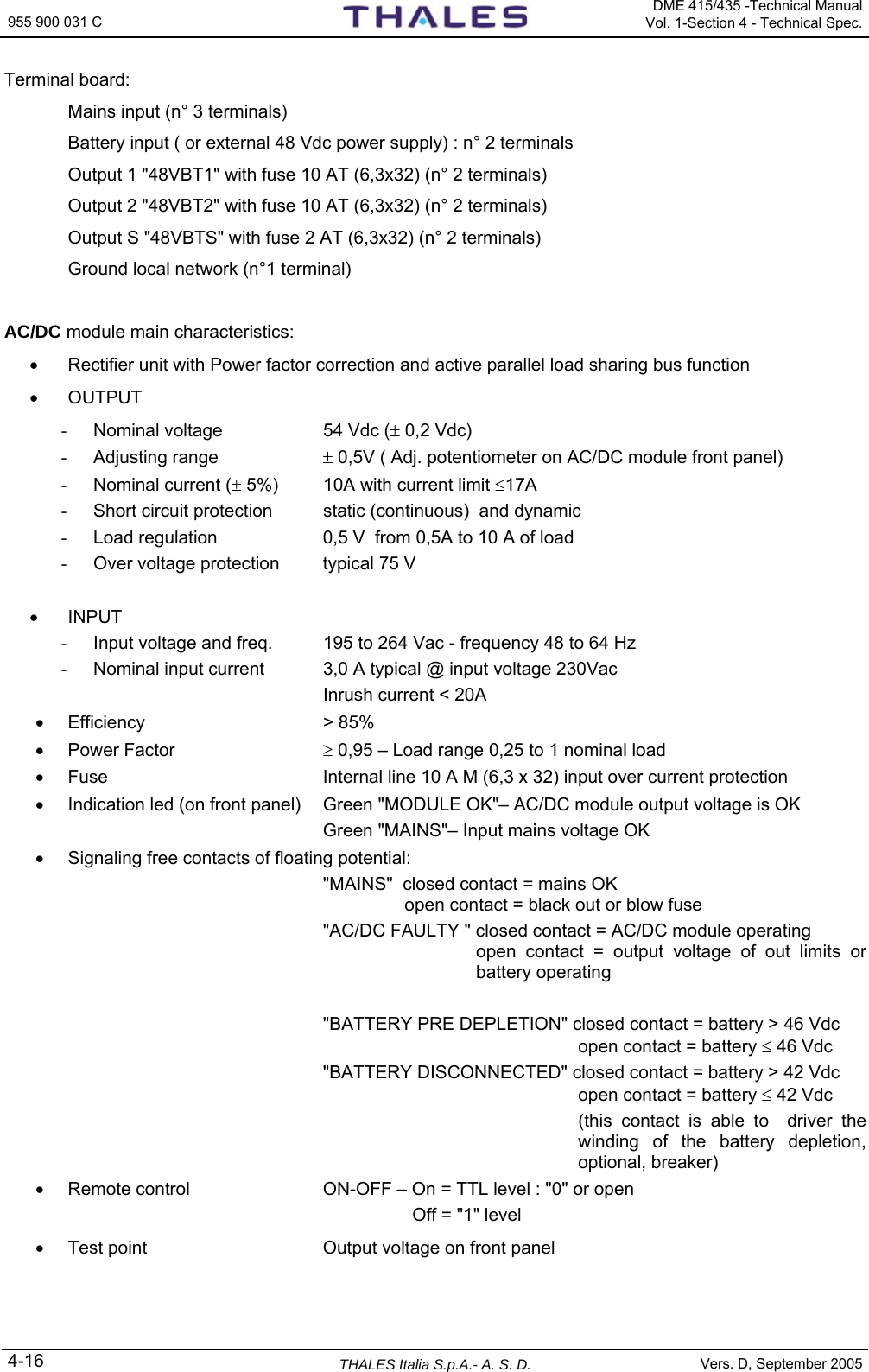
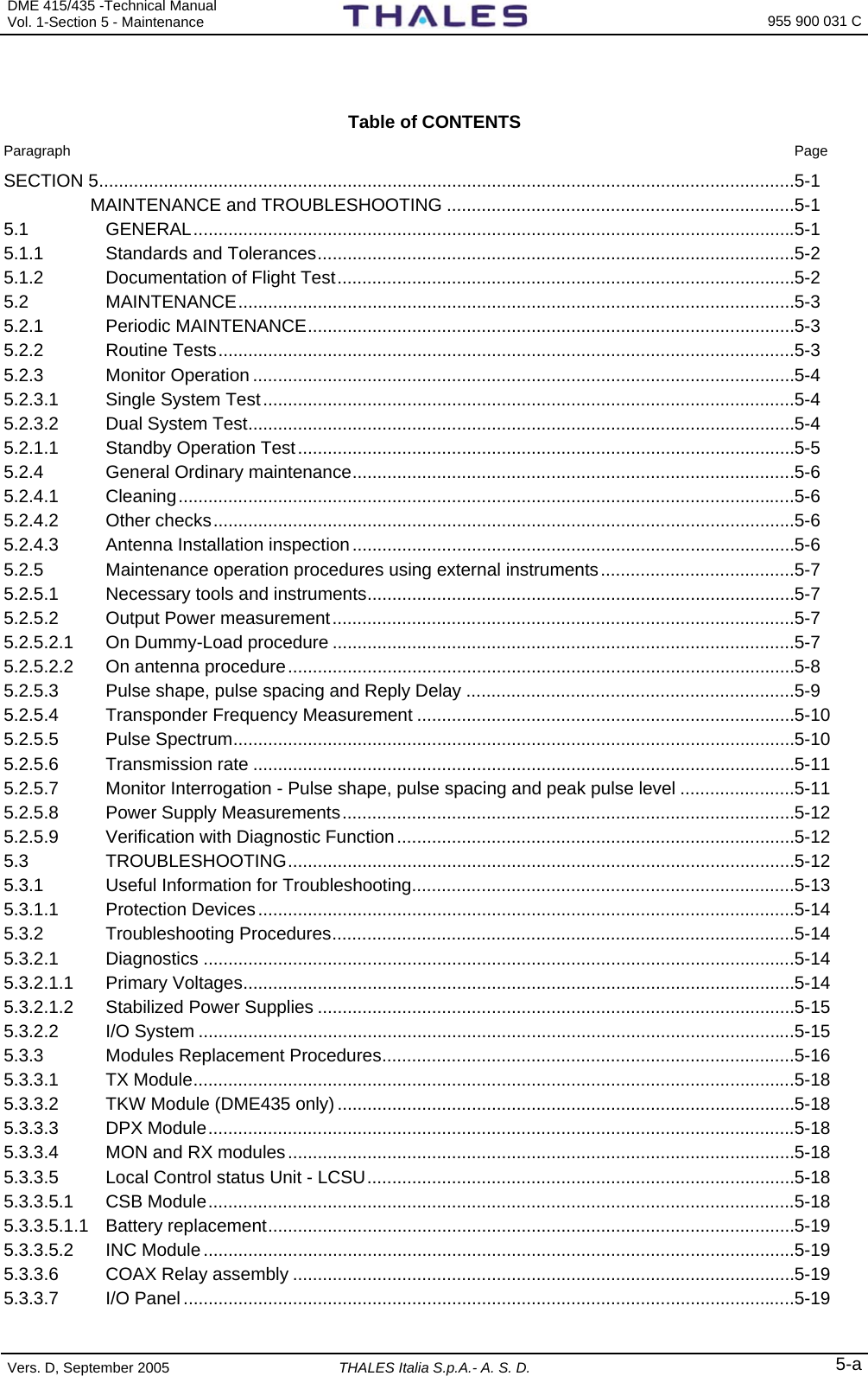
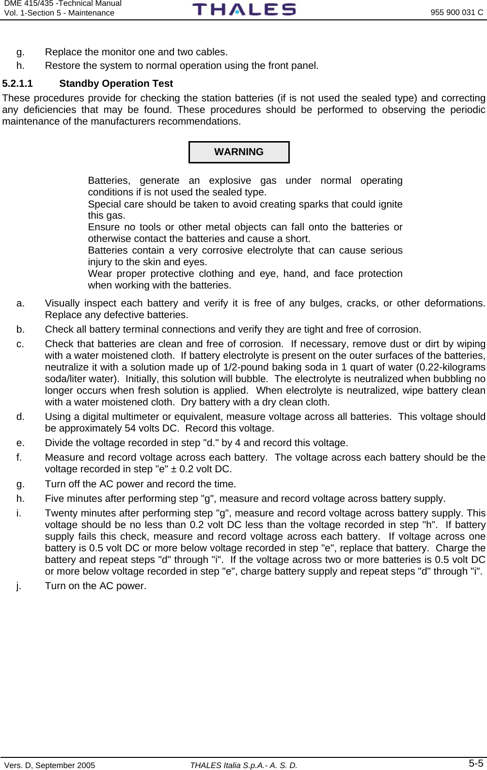
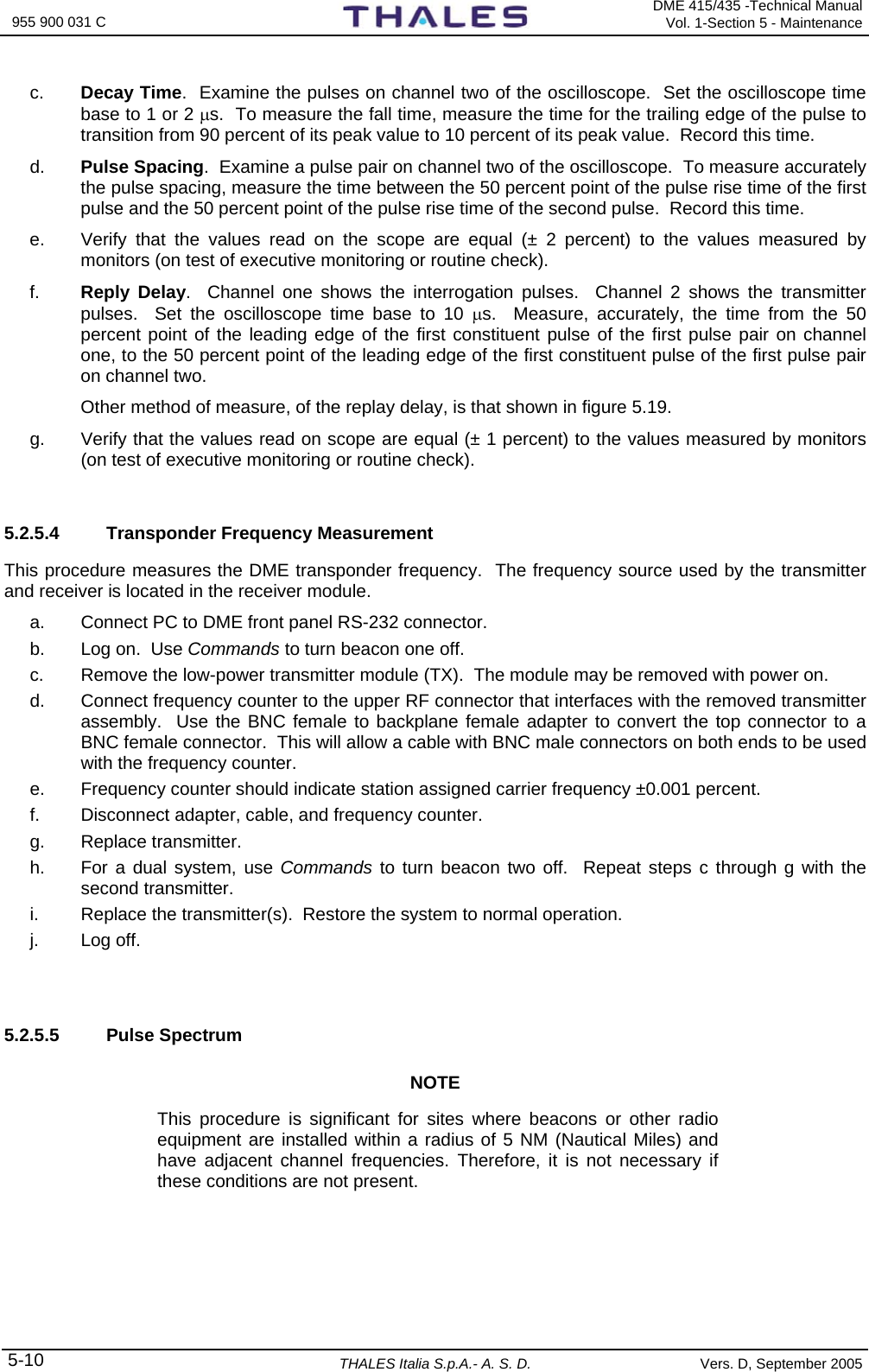
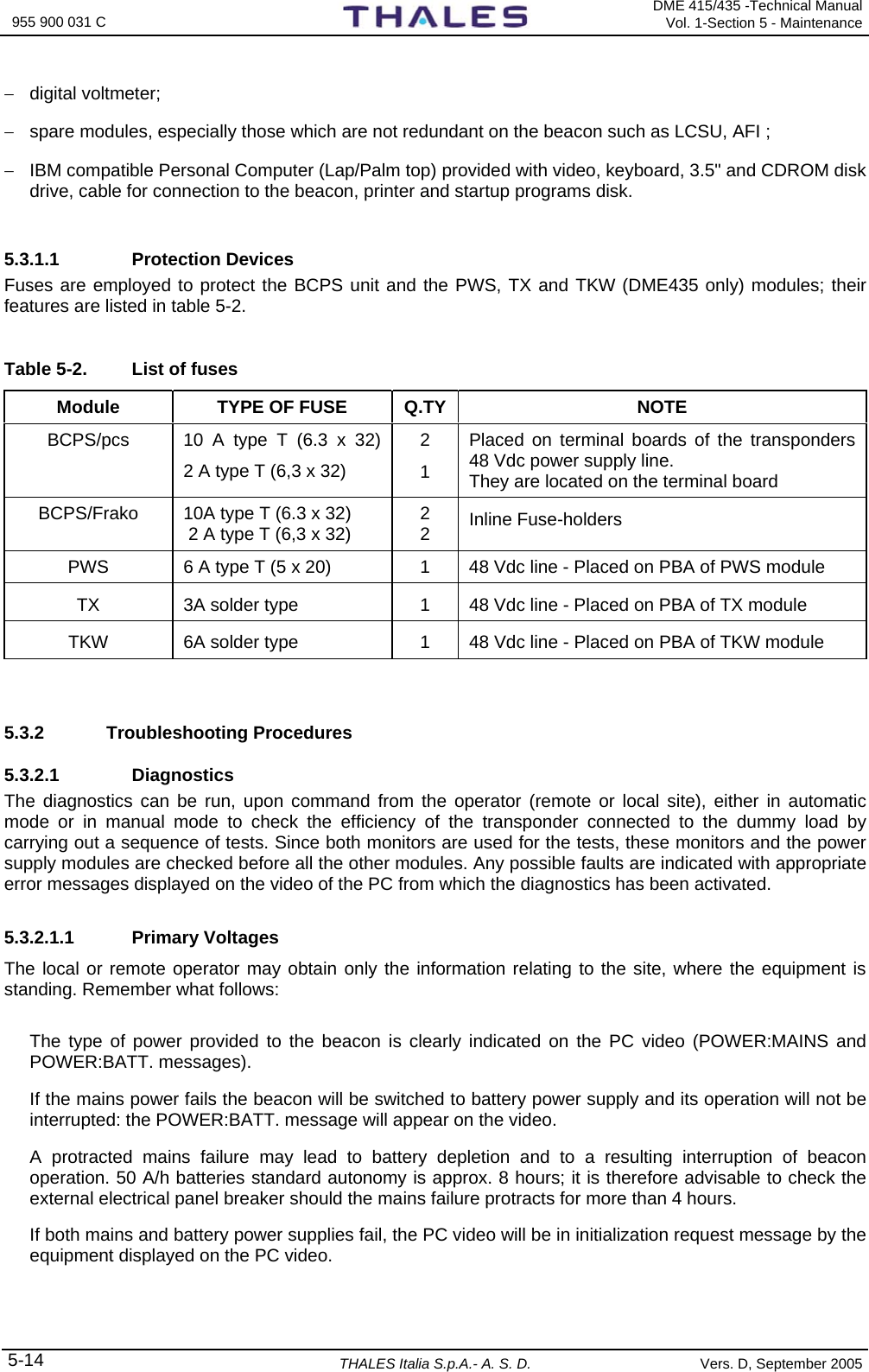
![955 900 031 C DME 415/435 -Technical Manual Vol. 1-Section 3 - Operation & Use 3-8 THALES Italia S.p.A.- A. S. D. Vers. D, September 2005 3.2.2.2 System Overview Selecting option [1] from the Main Menu the example video page shown in figure 3.3 is displayed. The goal of this screen is to show to the operator some important feature of the software: − Internal NAME of the equipment (CODE & MANUFACTURER); − Programmable COMMUNICATION line; − Number of the STATES and COMMANDS allowed for each equipment; For each equipment: − Number of History DATABASE provided; − Number of DIGITAL I/O specific for the equipment. These informations are useful during configuration job. All the informations of this screen are fixed. LCSU Maintenance Program System Overview V1.01-DMXXU101 Name Code States Dbases Dig_out | | | | | | | | | | Index | Mnfct | Comms | Cmds | Dig_in | | | | | | | | | | | --- ---------------- --- --- --- --- --- --- --- --- [0] LCSU Unit 0 0 0 48 16 1 0 0 [1] ANS-DMEN 415/435 1 1 0 80 3 4 12 0 Press <ESC> to exit F1 - Import Data F2 - Export Data F5 - Clear Video F10 - Quit Figure 3.3. System Overview V1= actual version of software The items have the following meanings: Index: List of equipment managed by LCSU Name: Managed equipment codes Mnfct: Manufacturer 0 = LCSU System 1 = ANS (Thales) Code: Equipment code 0 = LCSU 1 = DME/N 2 = DME/P Comms: Number of Communications Serial Port used LCSU = 0 (No Port used) DME = 0 States: Quantity of state messages available LCSU = 48 DME = 80](https://usermanual.wiki/Thales-ATM/435.USERS-MANUAL-2/User-Guide-857503-Page-62.png)
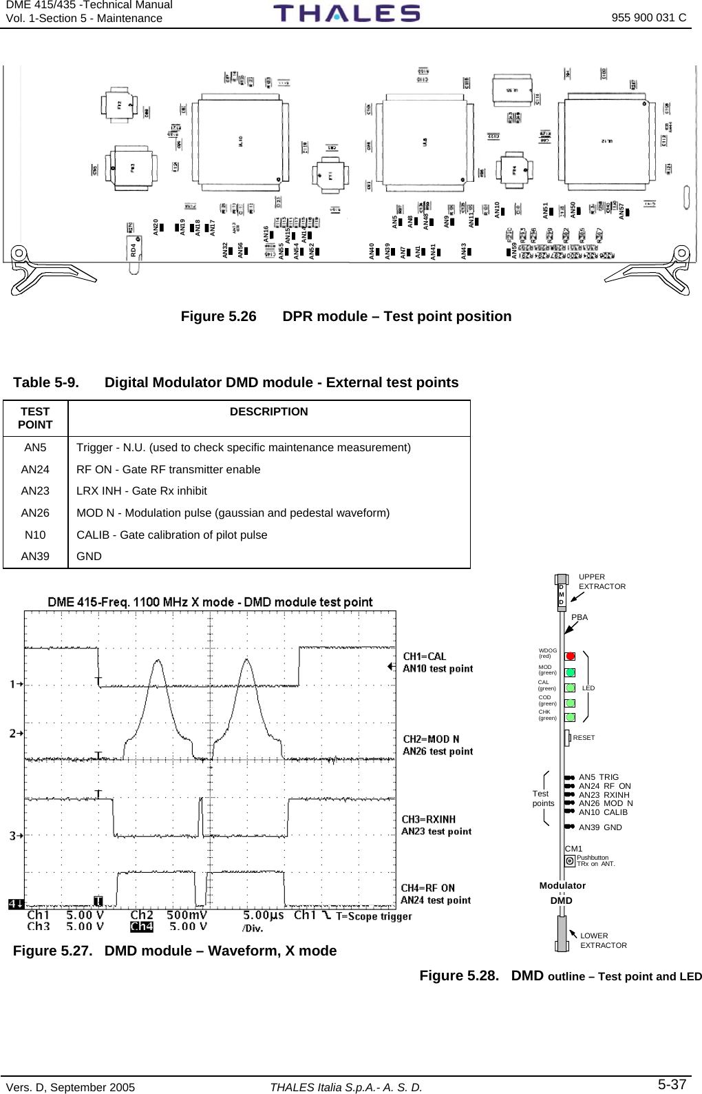
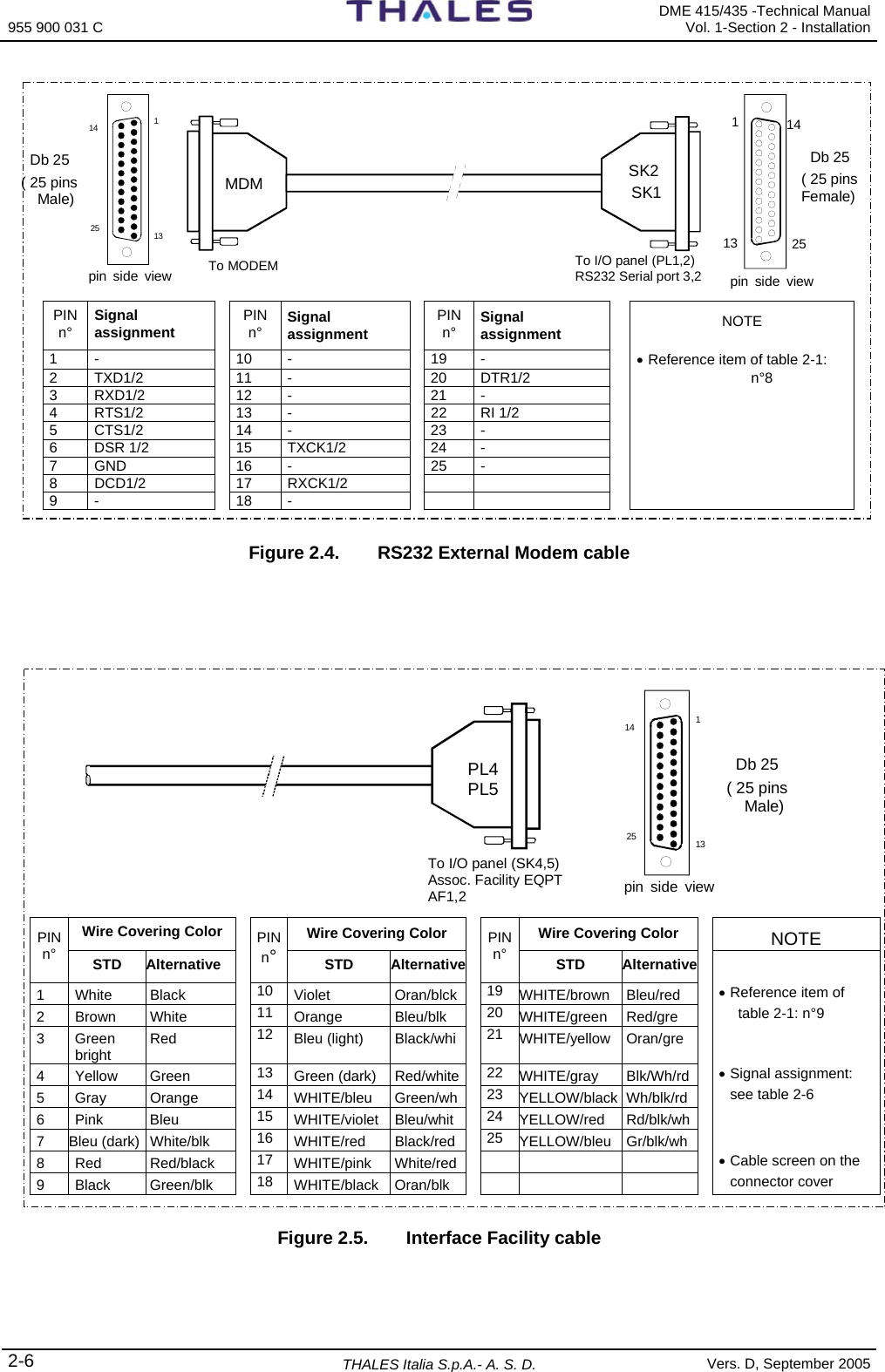
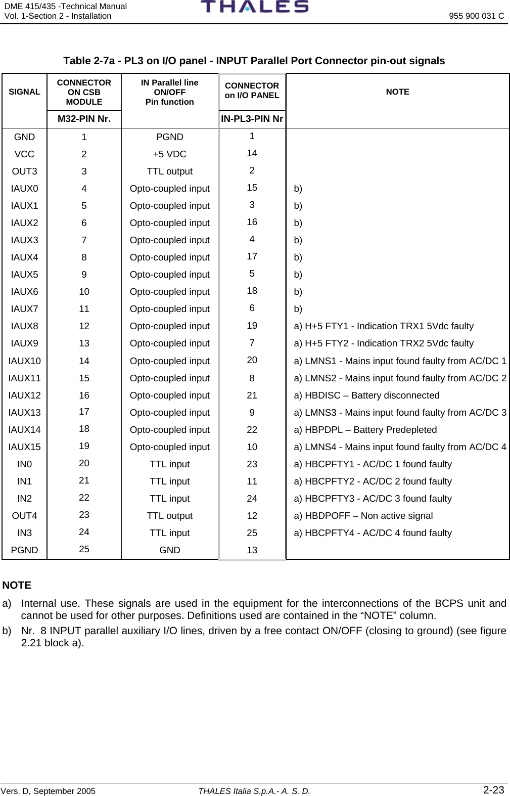
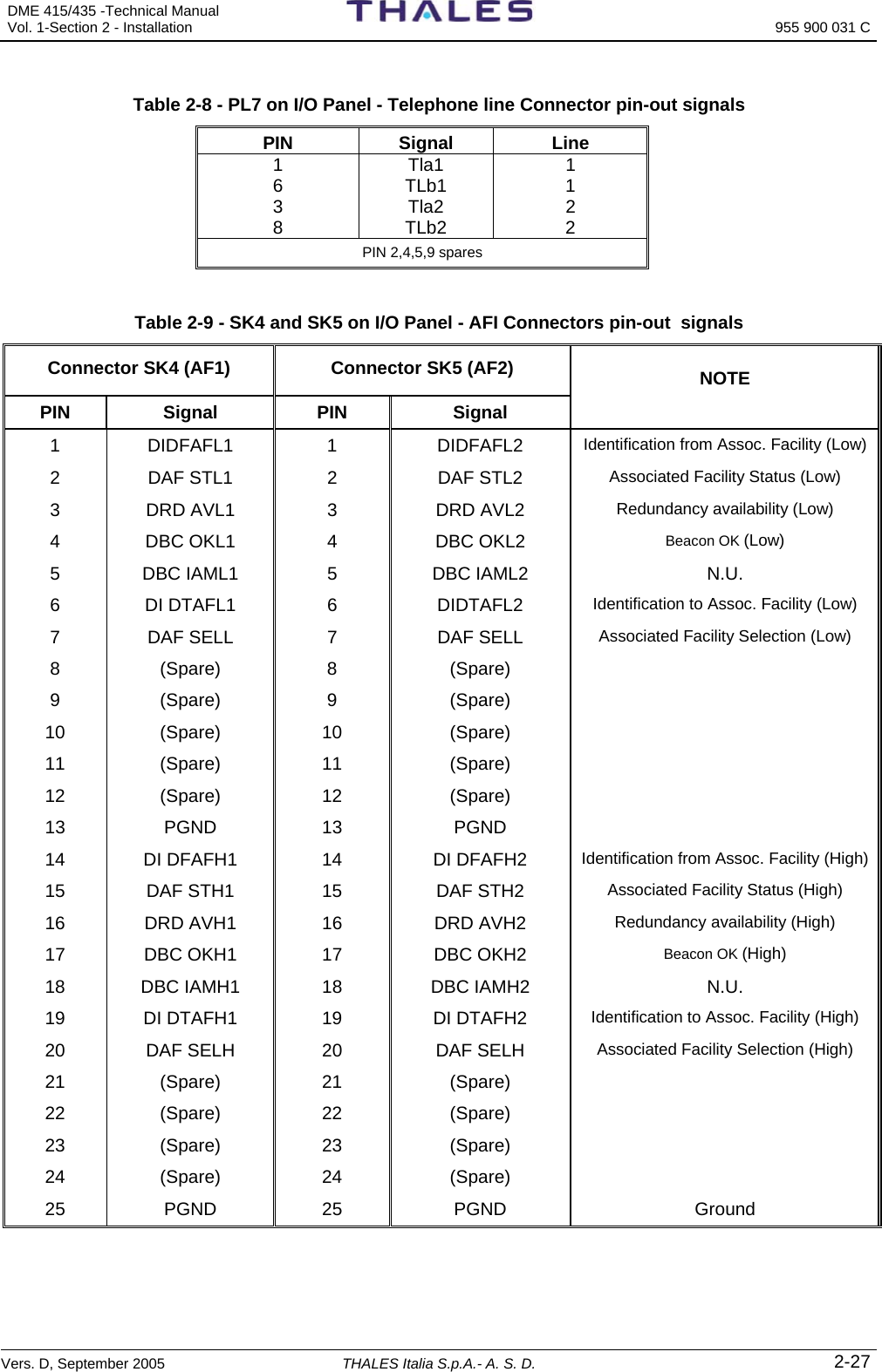
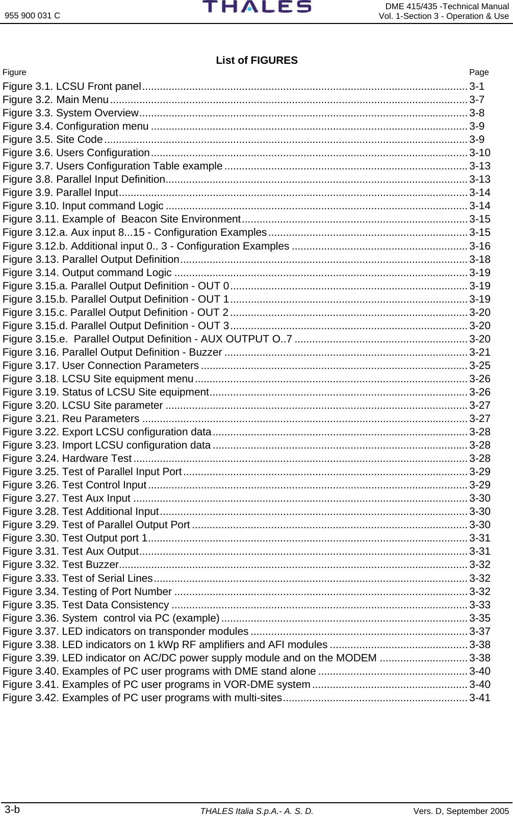
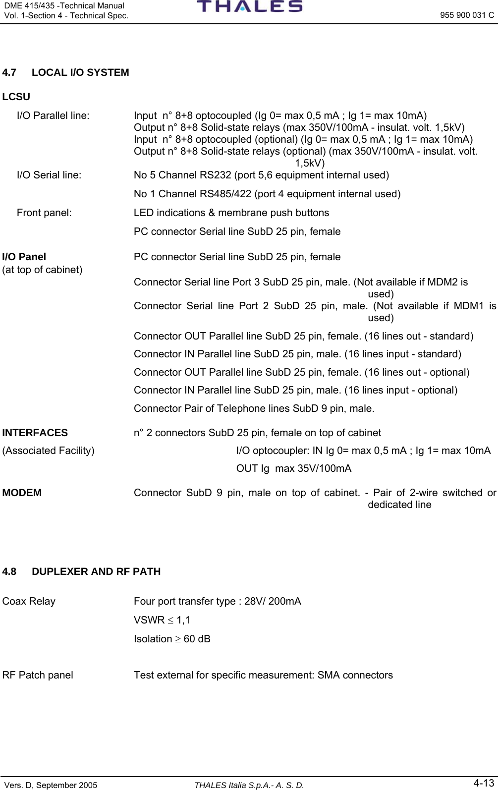
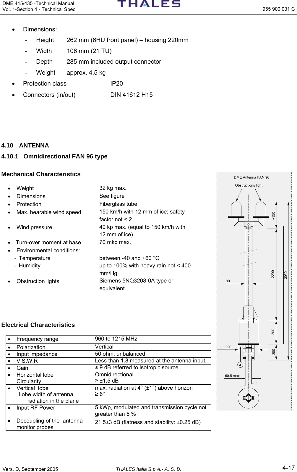
![DME 415/435 -Technical Manual Vol. 1-Section 3 - Operation & Use 955 900 031 C Vers. D, September 2005 THALES Italia S.p.A.- A. S. D. 3-9 Cmds: Max. quantity of commands managed LCSU = 16 DME = 3 Dbases: Data Bases (History) associated to the equipment LCSU = 1 DME = 4 Dig_in: Parallel input lines - Number of lines for beacon management LCSU = 0 DME = 12 Dig_out: Parallel output lines - Number of lines for beacon management LCSU = 0 DME = 0 3.2.2.3 LCSU Configuration This screen groups the entire Submenu configuring the software and two option (EXPORT & IMPORT) to save SAVE/RESTORE the changes made. Selecting option [2] on the Main Menu displays the page shown in figure 3.4. LCSU Maintenance Program Configuration [1] LCSU Site code [2] Users configuration [3] Parallel input definition [4] Parallel output definition [5] User connection parameters [6] LCSU site equipment configuration [7] LCSU site parameters [8] Reu parameters [9] Export LCSU configuration data [10] Import configuration data [0] Return Select: F1 - Import Data F2 - Export Data F5 - Clear Video F10 - Quit Figure 3.4. Configuration menu 3.2.2.3.1 LCSU Site Code Select option [1] on the “Configuration” page to enter the beacon or site identity code as shown in figure 3.5. This screen allows the operator to change the SITE name, which is the name used by all the users (PC, RCSI 446 or RCSE445, SI 446) to communicate with the DME. Only CAPITAL letters and DIGIT are allowed. LCSU Maintenance Program LCSU Site code LCSU Site code THAL LCSU code (maximum 4 chars allowed): F1 - Import Data F2 - Export Data F5 - Clear Video F10 - Quit Figure 3.5. Site Code](https://usermanual.wiki/Thales-ATM/435.USERS-MANUAL-2/User-Guide-857503-Page-63.png)
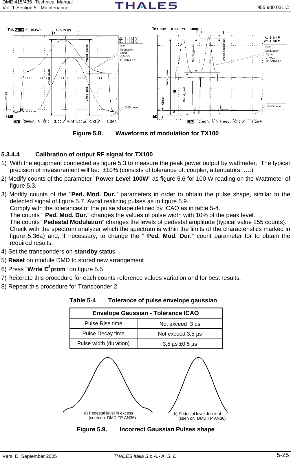
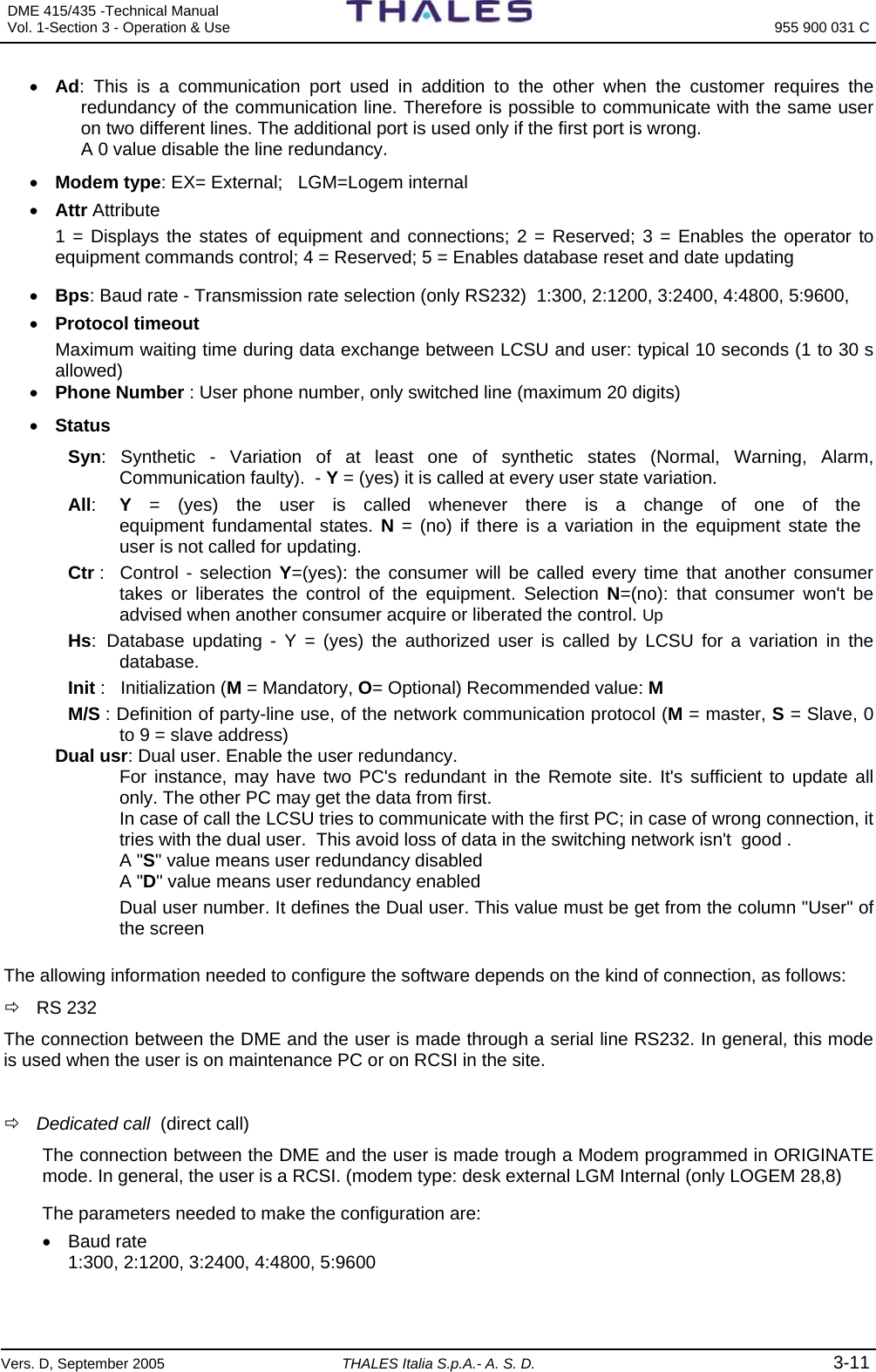
![955 900 031 C DME 415/435 -Technical Manual Vol. 1-Section 3 - Operation & Use 3-10 THALES Italia S.p.A.- A. S. D. Vers. D, September 2005 3.2.2.3.2 User Configuration Selecting option [2] from the “Configuration” menu displays, the example page shown in figure 3.6. LCSU Maintenance Program Users configuration Mode Com Port Attr Bps Prot Phone Number Status User | Ident | | Modem | | timeout | Syn Ctr Init M/S Dual | | | St Ad Type | | | | | All | Hs | S/D | usr --- ----- ---- -- -- ---- - ----- -- -------------------- - - - - - - -- - [1] Rs232 LCPC 1 5 9600 10 M [2] Rs232 RMPC 2 5 9600 10 M [3] Dis .. .. [10] Dis. User number: 1 F1 - Import Data F2 - Export Data F5 - Clear Video F10 - Quit Figure 3.6. Users Configuration This screen defines the parameters needed to manage the communication with the user: − Kind of connection (RS232, Dedicated, switched, party line); − Communication parameter (Port, Baud Rate, Protocol timeout); − Identifier of the User; − Kind of Modem (internal, external); − Dialing parameters (Phone number and call logic) meaningful for switched line only; − Master/Slave parameter (Party line only). For each kind the connection, are to configure: • User name Identifier of user. It is the NAME of the user known everywhere in the network. • Mode: Connection modes possible for each user 0 = Dis. (disabled: as if non existent) 1 = RS232C (type of serial line) 2 = Ded.Call (dedicated telephone line via modem in “originate” mode) 3 = Ded.Answ. (dedicated telephone line via modem in “answering” mode) 4 = switched 5 = Party line • Ident: Identity code name of user (max. 4 alphanumeric characters). • Com Port (Communication Port): Valid values are from 1 to 3 (CH1, CH2 and CH3). Port 4 to 6 are reserved for internal use of equipment. Port 1 is generally used for local connection (line maintenance PC), Port 2 and 3 are generally used with remote connection trough Modem (switched line, dedicated line or party line). • St : Status Request only with switched line modems - Changing any bit of the status word – Y (yes) the user is called upon a change of one of the main states of the equipment, N (no) in case of equipment state variations the user is not called for updating](https://usermanual.wiki/Thales-ATM/435.USERS-MANUAL-2/User-Guide-857503-Page-64.png)

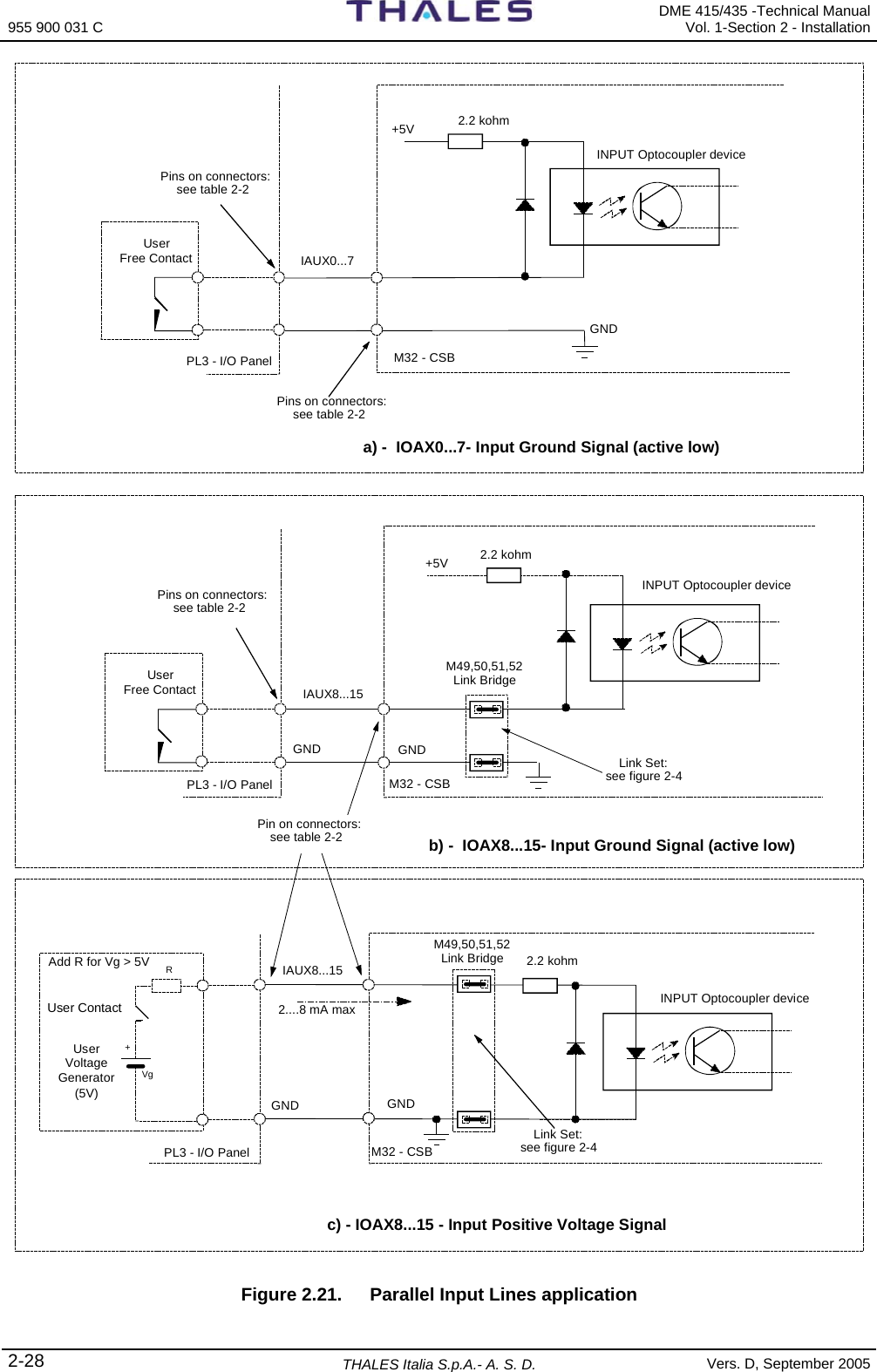
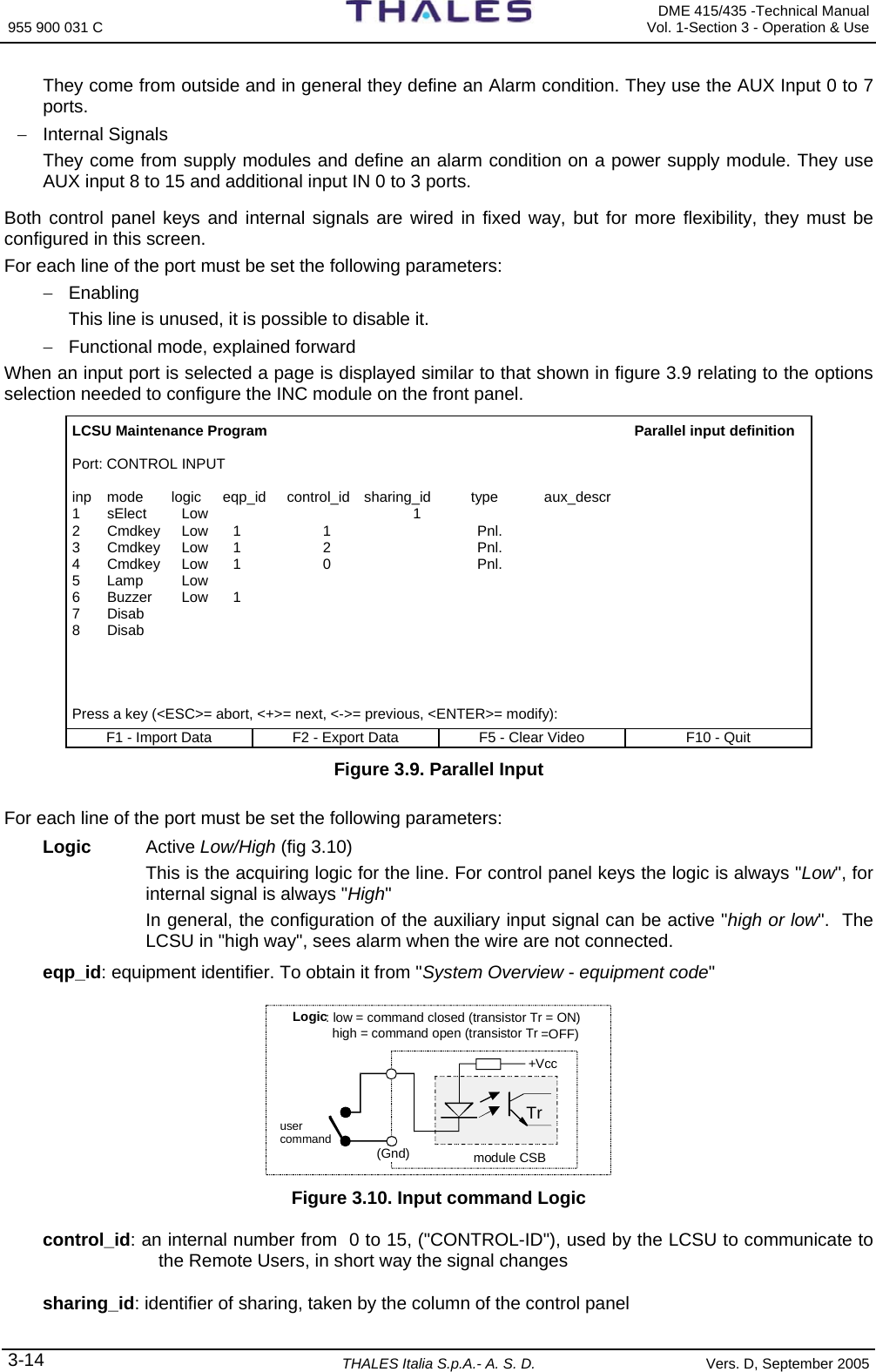
![DME 415/435 -Technical Manual Vol. 1-Section 3 - Operation & Use 955 900 031 C Vers. D, September 2005 THALES Italia S.p.A.- A. S. D. 3-13 LCSU Maintenance Program Users configuration Mode Com Port Attr Bps Prot Phone Number Status User | Ident | | Modem | | timeout | Syn Ctr Init M/S Dual | | | St Ad Type | | | | | All | Hs | S/D | usr --- ----- ---- -- -- ---- - ----- -- -------------------- - - - - - - -- - [1] Rs232 LCPC 1 5 9600 10 M [2] Rs232 RMPC 2 5 9600 10 M [3] Ded.A IJKL 5 Ext. 5 2400 10 M [4] Swt MNOP 5 0 Lgm. 5 10 0123456789 Y Y Y Y M S [5] Swt UVXY 6 1 Ext. 5 10 22222222222 Y Y Y Y M D 2 [6] Dis [7] Dis [8] Dis [9] Dis [10]Dis User number: F1 - Import Data F2 - Export Data F5 - Clear Video F10 - Quit Figure 3.7. Users Configuration Table example 3.2.2.3.3 Parallel Input Definition Selecting option [3] in the “Configuration” menu the page is displayed, showing the ports and parallel input lines (figure 3.8) for the definition of the control logic. LCSU Maintenance Program Parallel input definition [n] port name [0] CONTROL INPUT [1] AUX INPUT 0..7 [2] AUX INPUT 8..15 [3] ADDITIONAL INPUT 0..3 Port: F1 - Import Data F2 - Export Data F5 - Clear Video F10 - Quit Figure 3.8. Parallel Input Definition The ports and input lines listed are relevant to (signals AUX In- ON/OFF): − [0] CONTROL INPUT 0 = Managing controls and beacon commands − [1] AUX INPUT 0..7 = Inputs to connector PL3 on the I/O panel (from AUX 0 to AUX 7) − [2] AUX INPUT 8..15 = Inputs to connector PL3 on the I/O panel (from AUX 8 to AUX 15) – [3] ADDITIONAL INPUT 0..3 = TTL inputs (from IN 0 to IN3) The goal of this screen is to allow the customer to define how manage the digital input signals. There are different kinds of signals: − Control panel keys Silent, Lamp, Select, Commands (Request/Release, Equipment ON/OFF, Changeover). They use the control input port. − Auxiliary Signals](https://usermanual.wiki/Thales-ATM/435.USERS-MANUAL-2/User-Guide-857503-Page-67.png)
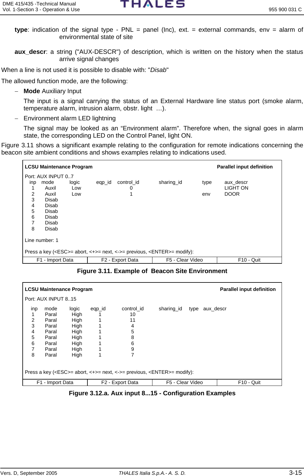
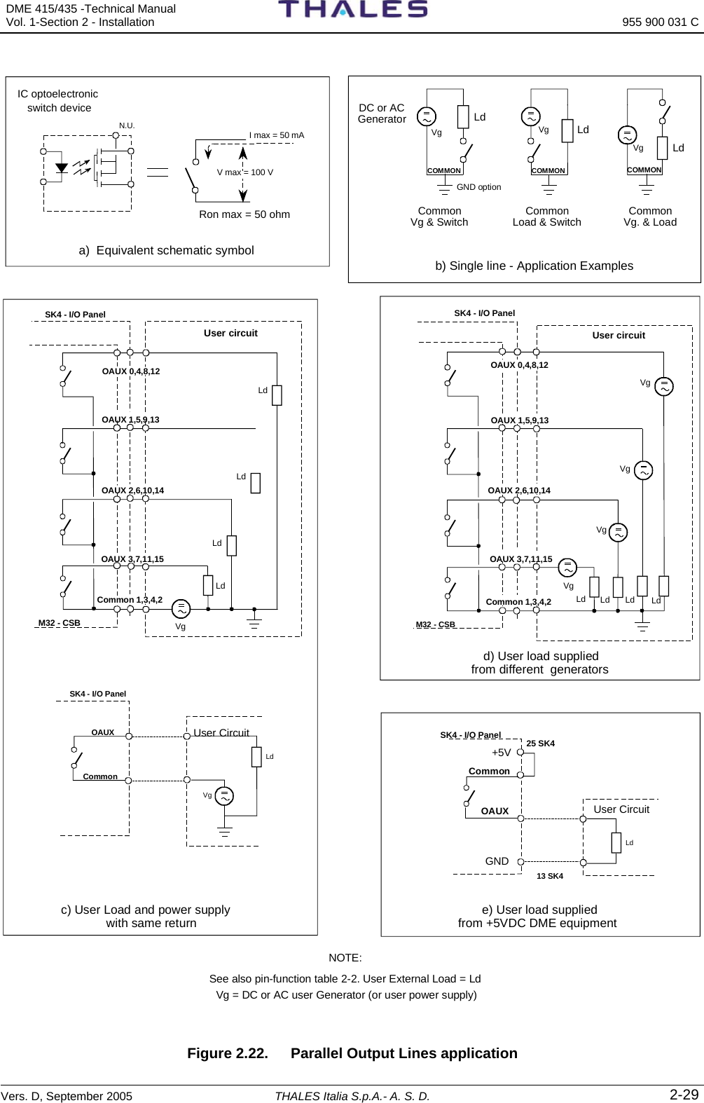
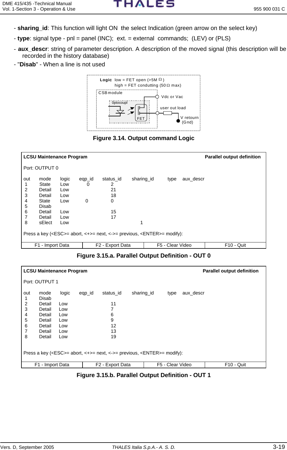
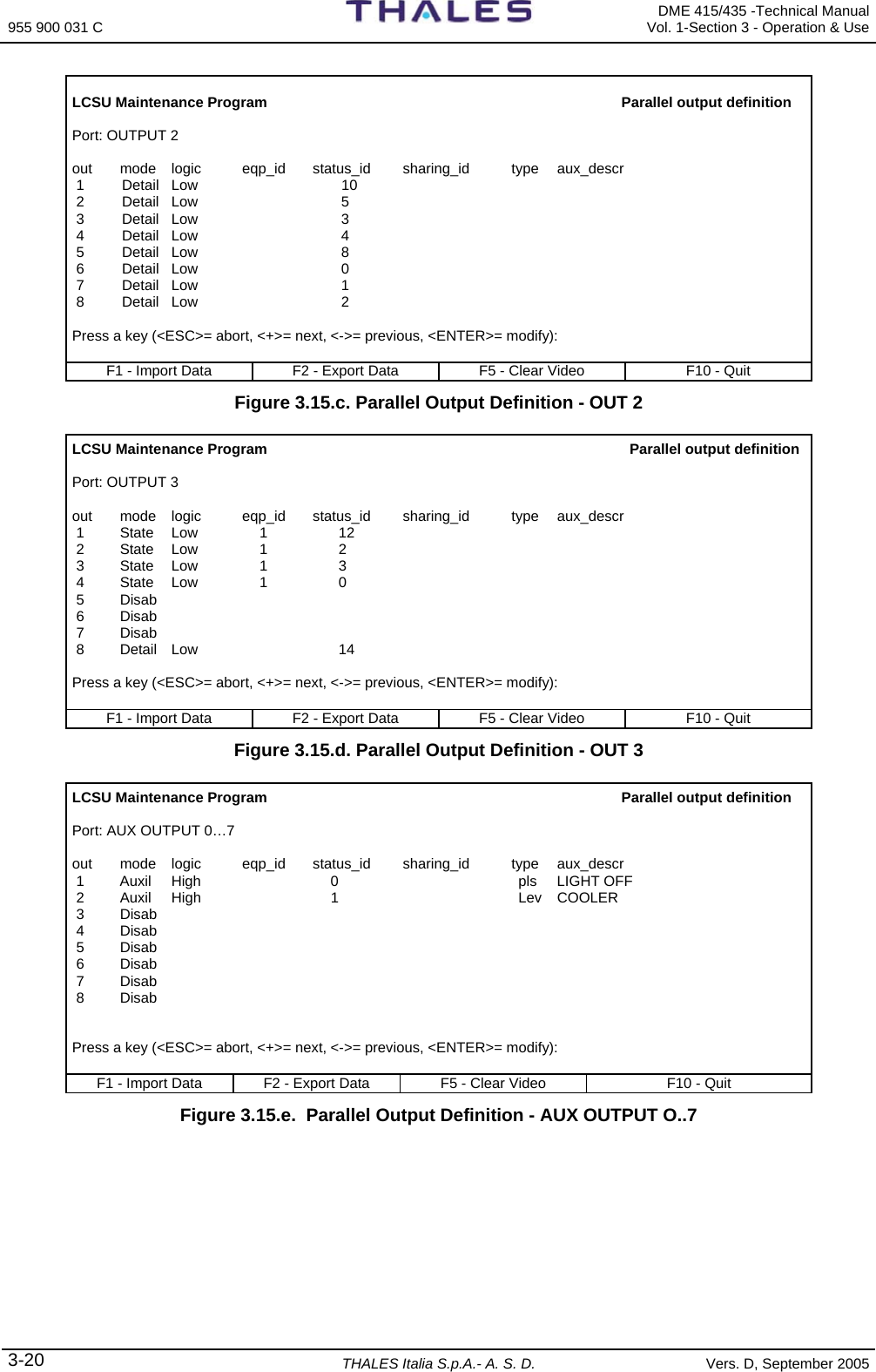
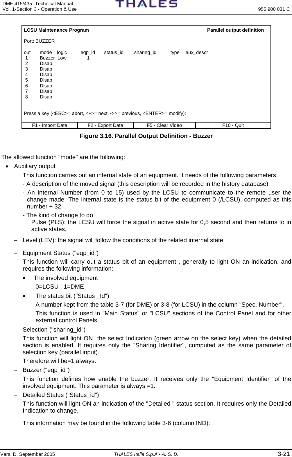
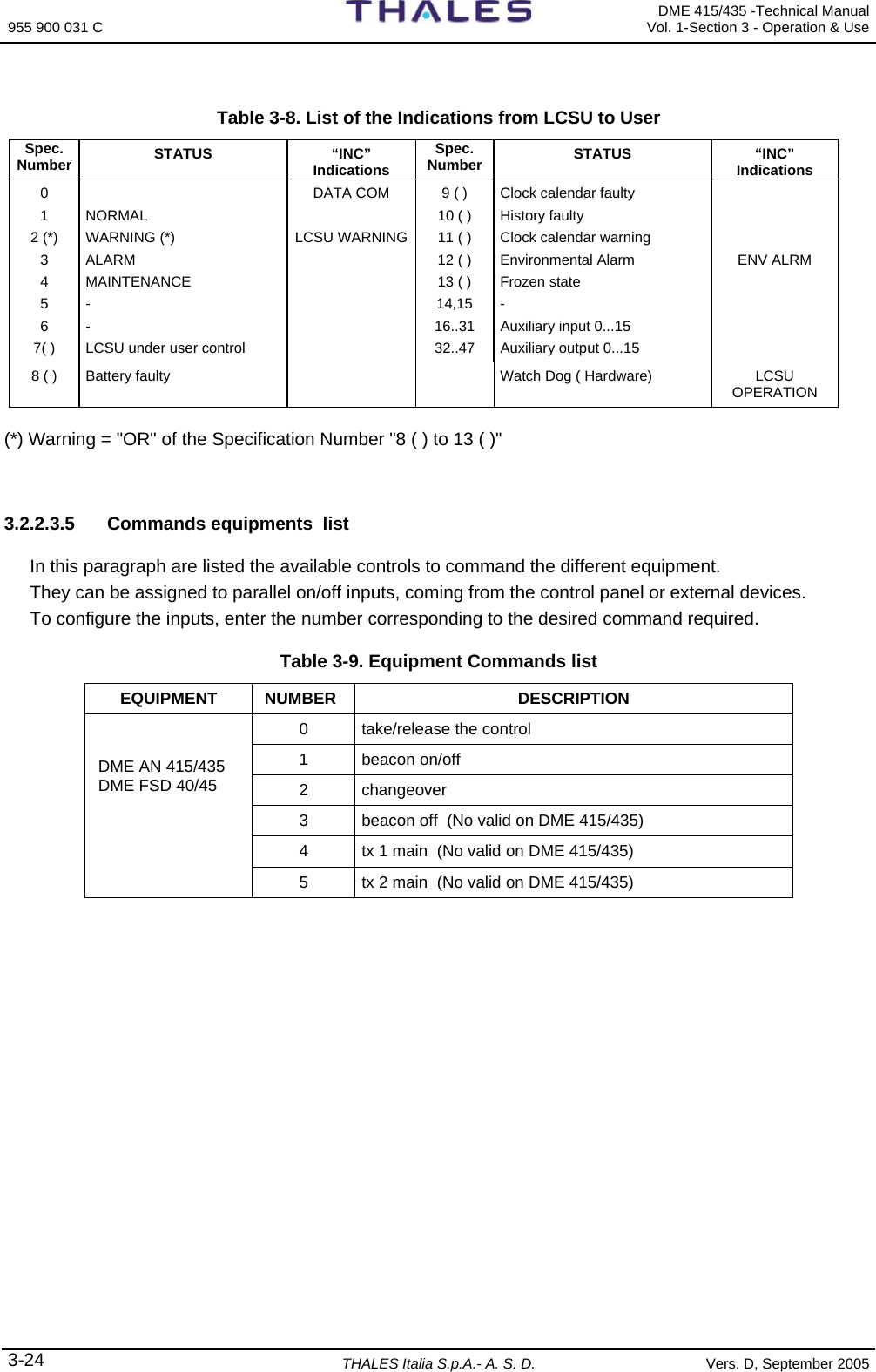
![955 900 031 C DME 415/435 -Technical Manual Vol. 1-Section 3 - Operation & Use 3-18 THALES Italia S.p.A.- A. S. D. Vers. D, September 2005 3.2.2.3.4 Parallel Output Definition Selecting option [4] in the “Configuration” menu the page is displayed showing the ports and parallel output lines (figure 3.13) for the definition of the control logic. The ports and output lines listed in figure 3.13 are relevant to: − [0], [1], [2], [3] OUTPUT 1, 2, 3, 4 = INC module indications − [4], [5] AUX OUTPUT 1, 2 = AUX 0..15 outputs − [6] ADDITIONAL OUTPUT 0..4 − [7] BUZZER = Buzzer activation LCSU Maintenance Program Parallel output definition [n] port name [0] OUTPUT 0 [1] OUTPUT 1 [2] OUTPUT 2 [3] OUTPUT 3 [4] AUX OUTPUT 0..7 [5] AUX OUTPUT 8..15 [6] ADDITIONAL OUTPUT 0..4 [7] BUZZER Port: F1 - Import Data F2 - Export Data F5 - Clear Video F10 - Quit Figure 3.13. Parallel Output Definition When a port or an output line is selected, a page is displayed similar to that shown in figures 3.15 relating to the options selection [0,1,2,3] needed to configure the INC module on the front panel, and figure 3.16 to configure the BUZZER. The goal of this screen is to allow the customer to define how manage the digital output signals. They are different kinds of signals − Control Panel Indications "Detailed indication", Main Status Indication, "LCSU" Indications, "Station" Indication, Buzzer. They use the ports output 0,1,2,3 and Buzzer − Auxiliary Output Signals They carry out to outside some internal status of interest for the customer. They use the AUX output 0 to 7, AUX output 8 to 15 and Additional output 0 to 4 ports. − Parallel Internal Output AUX 0 to 4 Not provided The Control Panel indications are wired in fixed way, but for more flexibility, they must be configured too. For each line of the port must be set the following parameters: - Out - group of output lines - mode - Functional mode description - logic: Active Low/High Level (see figures 3.14 and 3.15). It defines how change the status of the signal. The indication of the control panel acquires a "Low" state to light ON. - eqp_id: This function will carry out a status bit of an equipment , generally to light ON an indication - status_id: This function will light ON an indication of the "Detailed " status section.](https://usermanual.wiki/Thales-ATM/435.USERS-MANUAL-2/User-Guide-857503-Page-72.png)
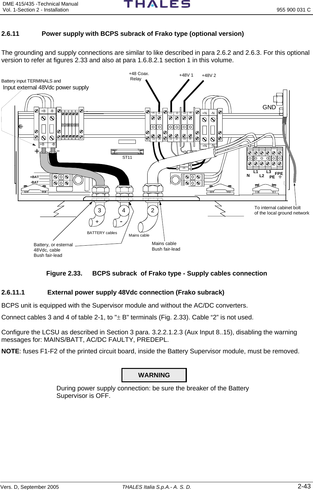
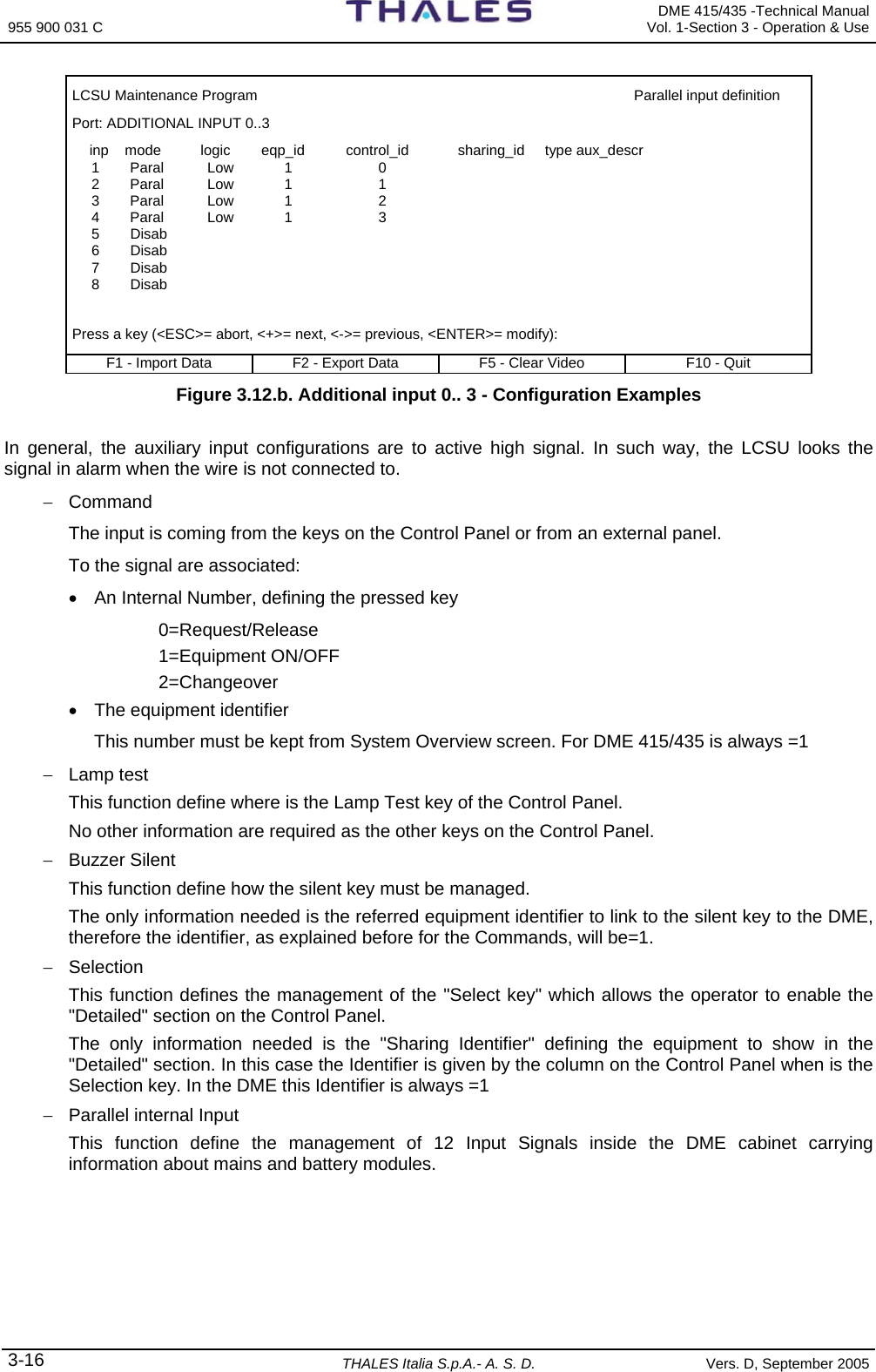
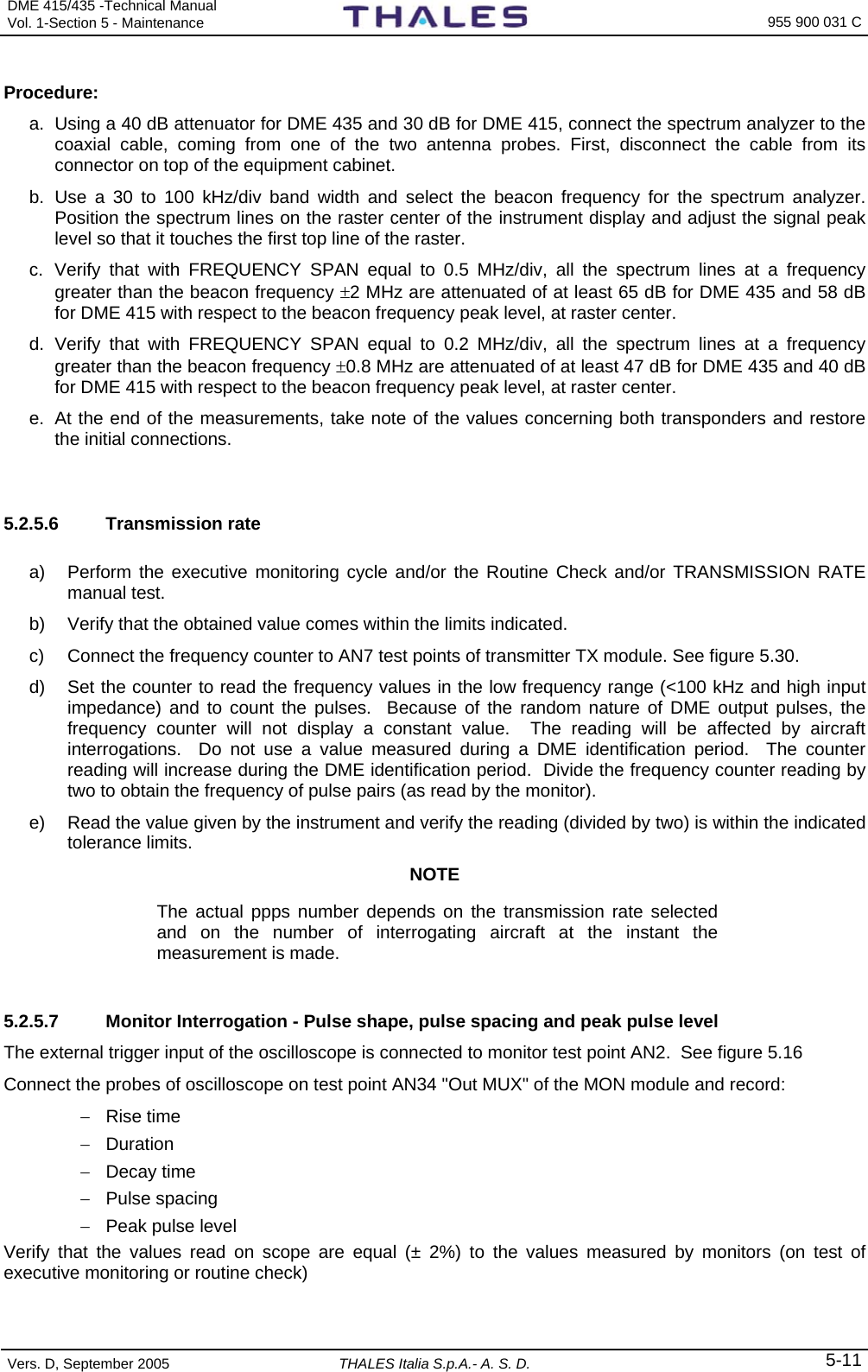
![DME 415/435 -Technical Manual Vol. 1-Section 3 - Operation & Use 955 900 031 C Vers. D, September 2005 THALES Italia S.p.A.- A. S. D. 3-25 3.2.2.3.6 User Connection Parameters Select option [5] on the “Configuration” menu to display the page shown in figure 3.17 that enables modification of some modem connection parameters. LCSU User connection parameters Leased line parameters [0] Connection attempt duration: 60 sec. (20 - 120) Switched line parameters [1] Connection speed: 3 (1: 300 , 2: 1200, 3: 2400, 4: 4800, 5: 9600) [2] Dial attempt duration: 90 sec (20 - 120). [3] 2nd call delay: 2 min. [4] 3rd call delay: 5 min. [5] 4th call delay: 10 min. [6] Subsequent calls delay: 0 min. (0: disabled) [7] Full connect. idle timeout: 0 min. (0: disabled) [8] Delay before call-back: 10 sec. [9] Call back 0 (0:disable 1:enable) Party line parameters [10] Preliminary waiting time: 0 sec (1 - 5000, 0:disable) [11] Post waiting time: 0 sec (1 - 5000, 0:disable) Up to march 05 [12] Intermediate waiting time: 0 sec (1 - 5000, 0:disable) Select: F1 - Import Data F2 - Export Data F5 - Clear Video F10 - Quit Figure 3.17. User Connection Parameters Below the meanings of each parameter that can be modified are given: - Connection attempt duration time interval within which the connection in dedicated line should take place. - Connection speed Baud rate of the connection between LCSU and Modem - Dial attempt duration time interval within which the connection in switched line should take place - 2nd call delay time to wait before retry the second call in case of dial connection not made. – 0 means no retry - 3rd call delay time to wait before retry the 3rd call in case of dial connection not made. – 0 means no retry - 4th call delay time to wait before retry the 4th call in case of dial connection not made. – 0 means no retry - Subsequent calls delay delay time for subsequent calls - 0 (disabled): the user is not called again after an unsuccessful attempt. - Full connect. idle timeout maximum connection time allowed in full without exchange of messages. - Delay before call-back Delay between end of call and call-back. - Call back Call-back enable. When called, the LCSU recall the User in order to authorize it to send the commands, if enabled for this operation. Party-line parameters: waiting times of communication - Preliminary waiting time: 0 msec (1 - 5000, 0: disable) - Post waiting time: 0 msec (1 - 5000, 0: disable) Up to march 05 - Intermediate waiting time: 0 msec (1 - 5000, 0: disable)](https://usermanual.wiki/Thales-ATM/435.USERS-MANUAL-2/User-Guide-857503-Page-79.png)
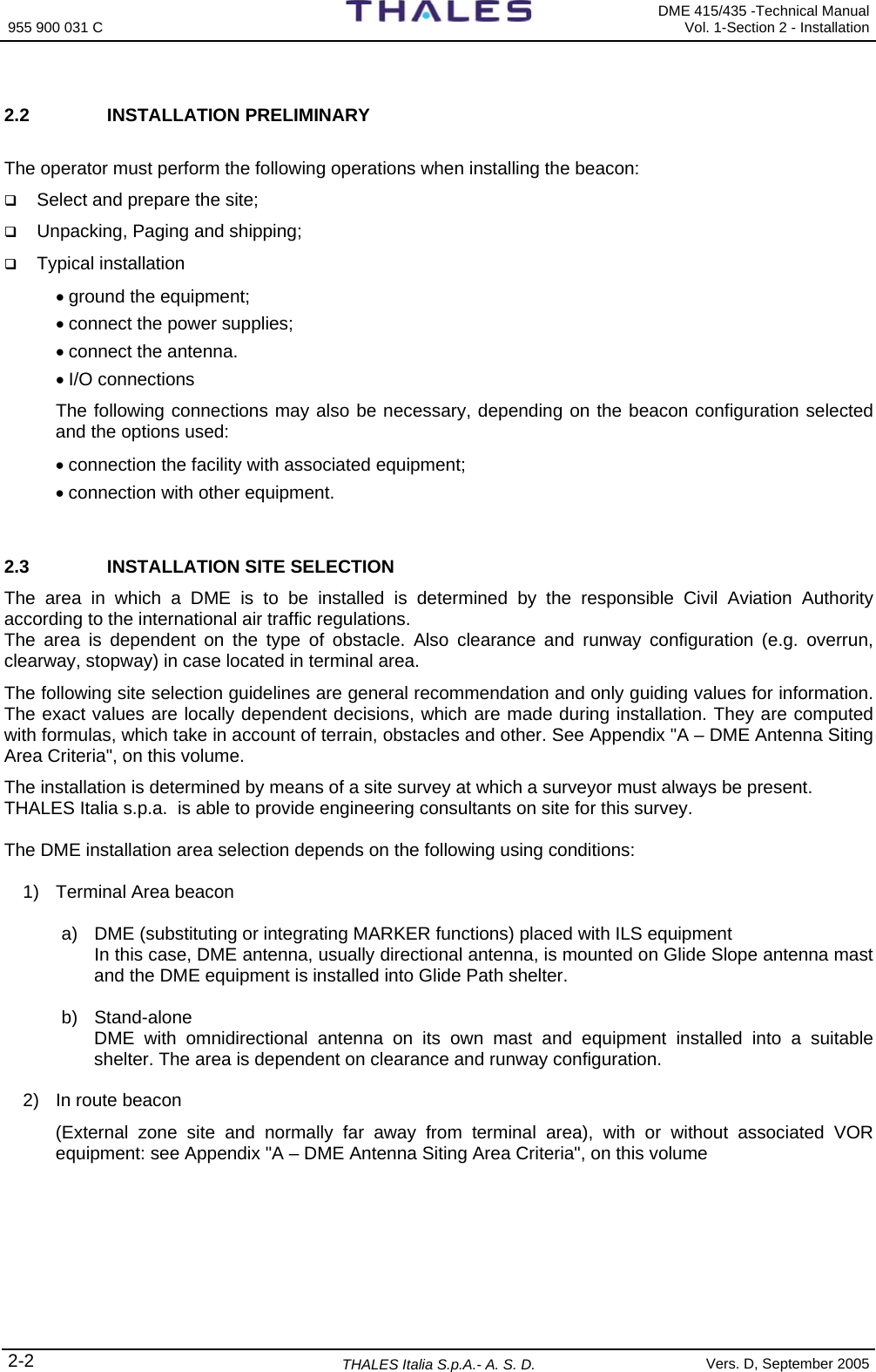
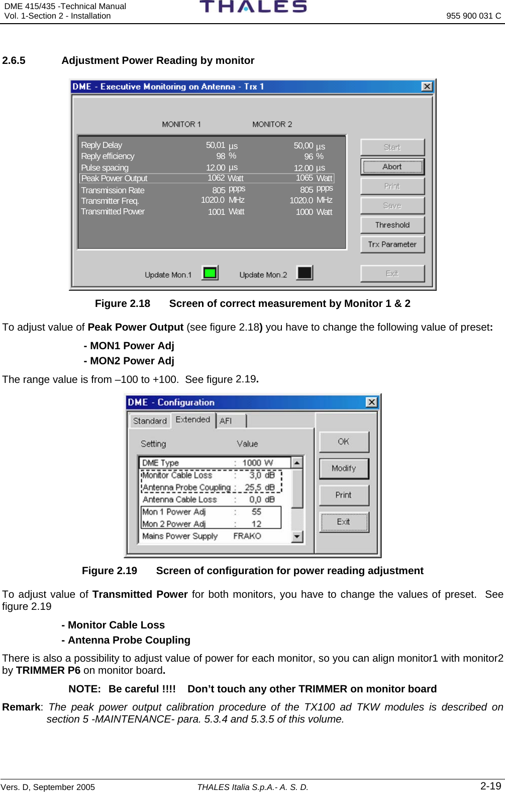
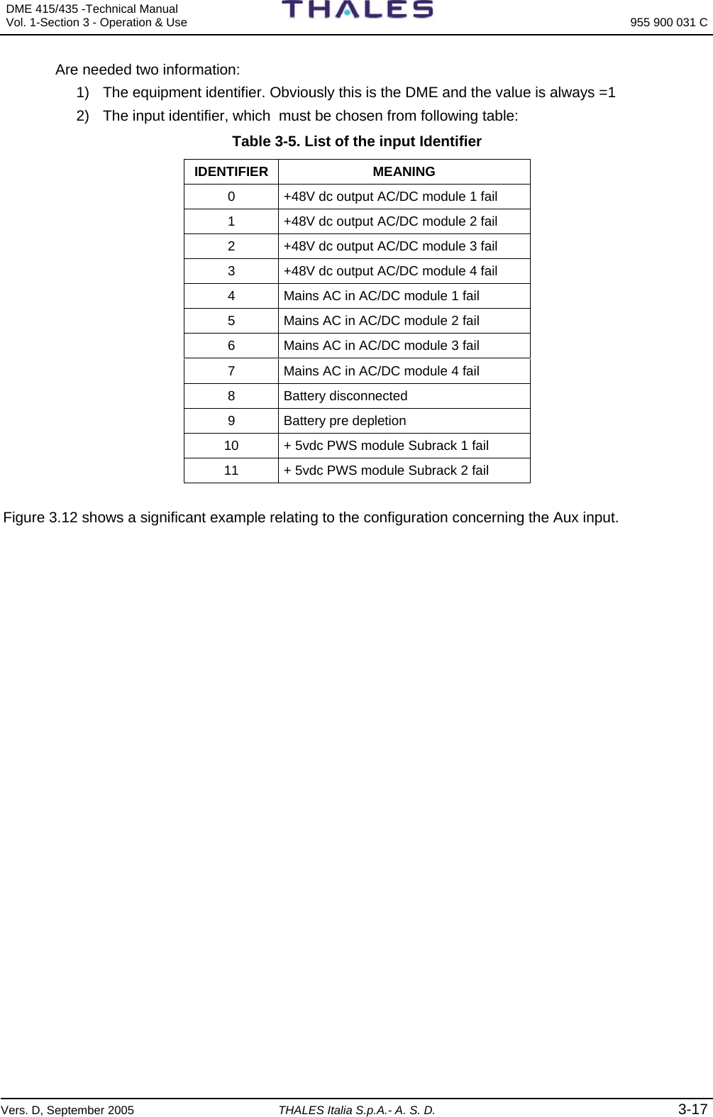
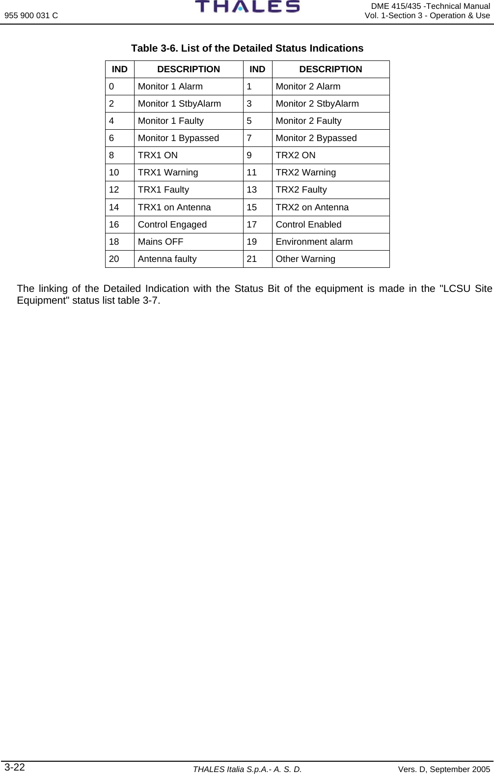
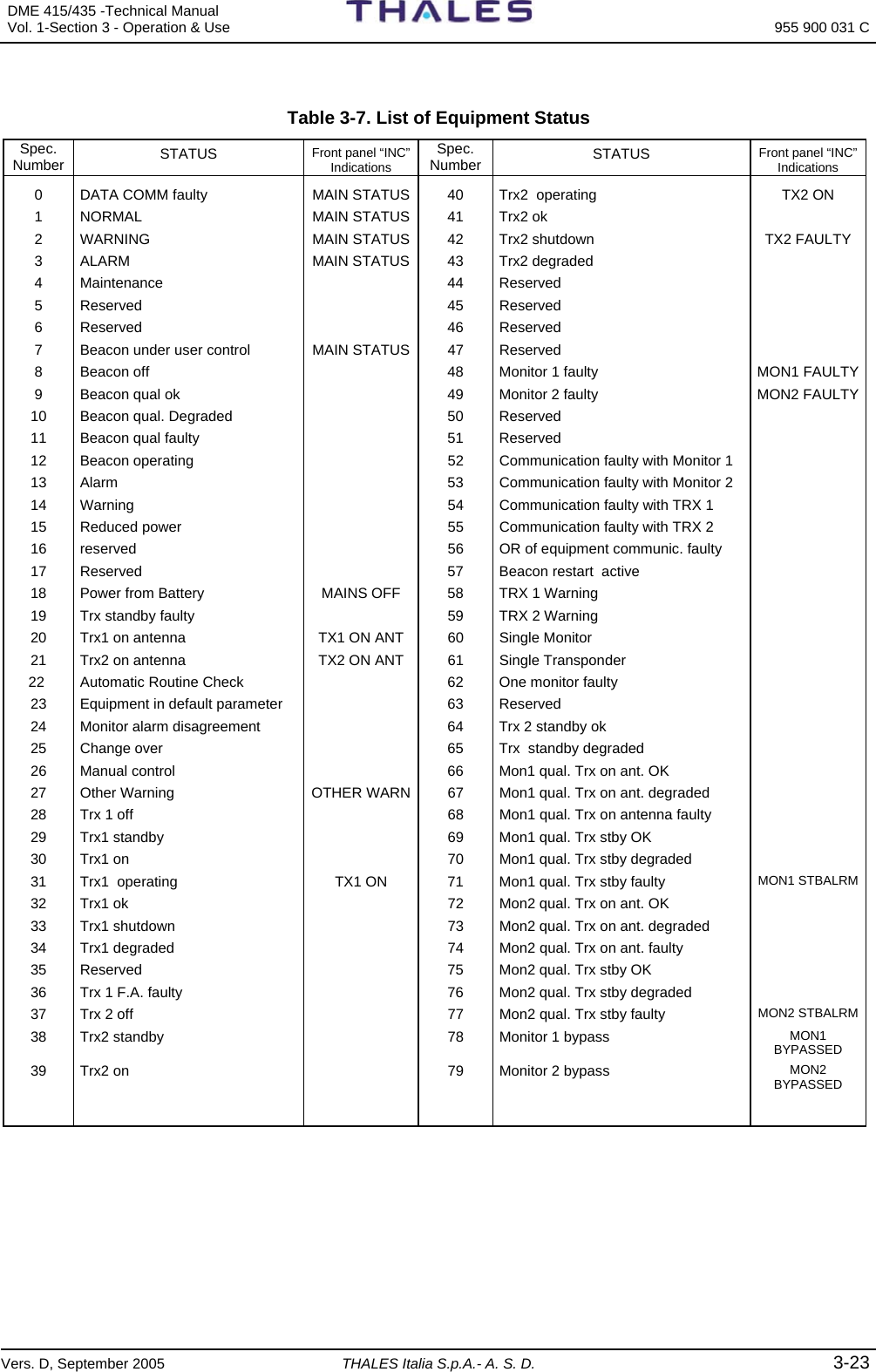
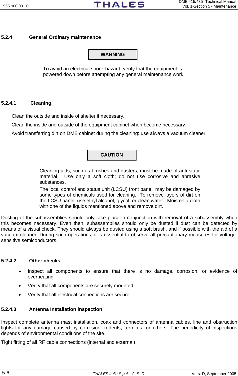
![955 900 031 C DME 415/435 -Technical Manual Vol. 1-Section 3 - Operation & Use 3-26 THALES Italia S.p.A.- A. S. D. Vers. D, September 2005 3.2.2.3.7 LCSU Site Equipment Configuration This screen option [6] (figure 3.18) allow the customer to link the outputs mapped as "Detailed" in the "Parallel Output Definition" to the Equipment Status (see table 3-7) - List of Equipment Status – The elements have the following effect: Description: description of the equipment to be represented Manuf: Producer: 0 = LCSU System, 1 = Thales (ANS) Eqp code equipment code: 0 = LCSU, 1 = DME/N, 2 = DME/P, 3 = NDB 436 Position in Main Status LCSU = Disab; 1 = equipment on which LCSU is assembled Select: 1 = line configuration; 2 = detailed status configuration Inserting selection 2 "Detailed status configuration" is shown the fig. 3.19 First must be set the "position in Main Status", that indicates the position on the Control Panel, where is shown the equipment status. For the DME this position is always =0 The next sub-screen (figure 3.19) allows, doing the linking said before. Each selection is referred to an indication on the control Panel (in the Detailed Status section). The value to set must be kept in the table 3-7. A value=1 disable the indication. For instance, the DME doesn't have the status of the antenna, then the indication [20] (Antenna faulty) must be disabled. The indication [16] (control Engaged), [17] (control Enabled) and [19] (Environment Alarm) don't have any reference to the equipment status; therefore a value different than the 1 (disable) is shown as enabled. The indication [22] (Mains status label) allow the operator to define the label to set in the display on the main status LCSU Maintenance Program LCSU site equipment configuration [n] Description Manuf Equip. Code Position in Main status [0] LCSU unit 0 0 Dis [1] ANS-DMEN 415/435 1 1 1 Select: 1: Line configuration 2: Detailed Status Configuration F1 - Import Data F2 - Export Data F5 - Clear Video F10 - Quit Figure 3.18. LCSU Site equipment menu LCSU Maintenance Program LCSU site equipment configuration Equipment: 1 Position in Main status: 1 [0] Monitor 1 Alarm :68 [1] Monitor 2 Alarm :74 [2] Monitor 1 Stand-by Alarm :71 [3] Monitor 2 Stand-by Alarm :77 [4] Monitor 1 Faulty :48 [5] Monitor 2 Faulty :49 [6] Monitor 1 Bypassed :78 [7] Monitor 2 Bypassed :79 [8] Trx 1 On :31 [9] Trx 2 On :40 [10] Trx 1 Warning :58 [11] Trx 2 Warning :59 [12] Trx 1 Faulty :33 [13] Trx 2 Faulty :42 [14] Trx 1 On Antenna :20 [15] Trx 2 On Antenna :21 [16] Control engaged :Ena [17] Control engaged :Ena [18] Mains off :18 [19] Environment alarm :Ena [20] Antenna faulty :Dis [21] Other warning :27 [22] Main status label: THAL Select the item to change (0 to 22): F1 - Import Data F2 - Export Data F5 - Clear Video F10 - Quit Figure 3.19. Status of LCSU Site equipment](https://usermanual.wiki/Thales-ATM/435.USERS-MANUAL-2/User-Guide-857503-Page-80.png)
![DME 415/435 -Technical Manual Vol. 1-Section 3 - Operation & Use 955 900 031 C Vers. D, September 2005 THALES Italia S.p.A.- A. S. D. 3-27 3.2.2.3.8 LCSU Site Parameter This screen option [7] (figure 3.20) allow the operator to change some information about the site: [0] Number of changing before status freezing: This parameters allows the operator to stop the recording of some auxiliary input that changes is value too fast. This option prevent the history database is filled with a lot of unused records. [1] Control superside It defines how the LCSU must manage the Control Request coming from outside or from the control Panel when another user is controlling the equipment. Three choice are allowed: 1) Disable: a new Control Request is refused, an user that has the equipment control cannot be interrupted by another user 2) Enable: it is the opposite of the previous item, any user may keep the equipment control, interrupting any other user. 3) On Priority: this is the classic way to manage the Request. The control Request is accepted only if the requestor has an higher priority than the present owner. The Local Control Panel has the highest priority, than follows the local PC and the Remote Control RCSI. The priority is computed as the number of intermediate nodes between the user and equipment. LCSU Maintenance Program LCSU site parameter [0] Number of changing before status freezing: 0 (1-100, 0:disabled) Dis [1] Control superside: 1 (0:dis, 1:on prior, 2:Ena) Select: F1 - Import Data F2 - Export Data F5 - Clear Video F10 - Quit Figure 3.20. LCSU Site parameter 3.2.2.3.9 REU parameters Selecting option [8] in the “Configuration” menu the page of figure 3.21 is displayed. This screen enables the change to the parameters of the REU (When equipment is in station system with Remote Equipment Unit on RCSE unit, otherwise the values won't be considered). LCSU Maintenance Program Reu parameters [0] Lke Equipment address: 160 (0..4095) [1] Lke Reu address: 16 (0..4095) [2] Modem identifier: MODEM 001 Select: F1 - Import Data F2 - Export Data F5 - Clear Video F10 - Quit Figure 3.21. Reu Parameters This table must be compiles in a system of connection in telephone switched line with remote control type REU - Otherwise the values won't be considered. - In the option [0] some first line must be inserts the identifier of the LCSU: value to be deduced from the manual of the remote control REU to which is postponed - In the option [1] must be inserts the identifier of the remote control REU: value to be deduced from the manual of the remote control REU to which is postponed - In the option [2] must be inserts always the string "Modem 001" Identifiers of LCSU and of REU must have carry over in the file *. ptt to be loaded in the program of REU necessarily called "LLKE".](https://usermanual.wiki/Thales-ATM/435.USERS-MANUAL-2/User-Guide-857503-Page-81.png)
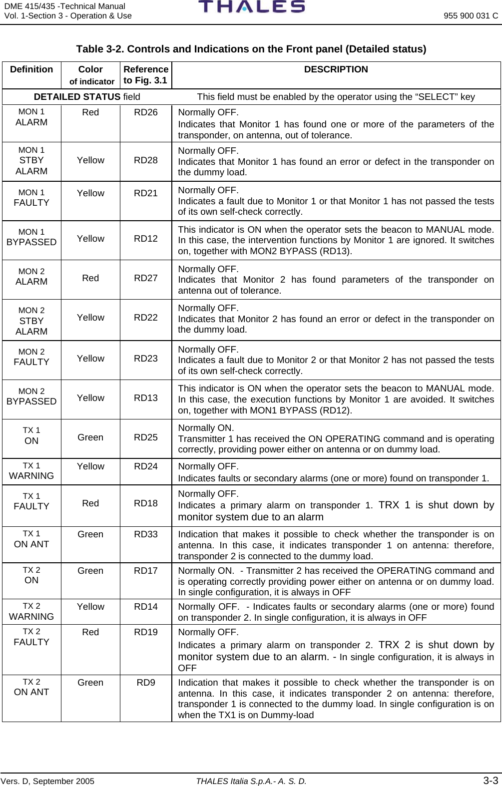
![955 900 031 C DME 415/435 -Technical Manual Vol. 1-Section 3 - Operation & Use 3-28 THALES Italia S.p.A.- A. S. D. Vers. D, September 2005 3.2.2.3.10 Export Configuration Data Select the option [9] on the menu “Configuration” to show on the display (fig. 3.22) the page with the procedure of export of the configuration data with the information: LCSU ready to send configuration dates to the PC. Press key F1 to transfer the configuration data from the LCSU to PC after entering the indication requested relevant to the name of the file where the data is to be stored. LCSU Maintenance Program Export LCSU configuration data LCSU ready to send configuration data to the PC Start the operation by pressing <F1> key. F1 - Import Data F2 - Export Data F5 - Clear Video F10 - Quit Figure 3.22. Export LCSU configuration data 3.2.2.3.11 Import Configuration Data To select the option [10] on the menu “Configuration” to show on the display (fig. 3.23), the page with the procedure of import of the configuration data with the information: LCSU ready to get configuration dates from the PC. Press key F2 to start the configuration data loading from PC to LCSU. LCSU Maintenance Program Import LCSU configuration data LCSU ready to get configuration data from the PC Start the operation by pressing <F2> key. F1 - Import Data F2 - Export Data F5 - Clear Video F10 - Quit Figure 3.23. Import LCSU configuration data 3.2.2.3.12 Hardware Test Select option [3] from the Main menu to display the page shown in figure 3.24 containing the options relating to functionality verification of the input and output ports and the control emulating the serial lines. LCSU Maintenance Program Hardware Test [1] Test of parallel input port [2] Test of parallel output port [3] Test of serial lines [0] Return Select: [] F1 - Import Data F2 - Export Data F5 - Clear Video F10 - Quit Figure 3.24. Hardware Test](https://usermanual.wiki/Thales-ATM/435.USERS-MANUAL-2/User-Guide-857503-Page-82.png)
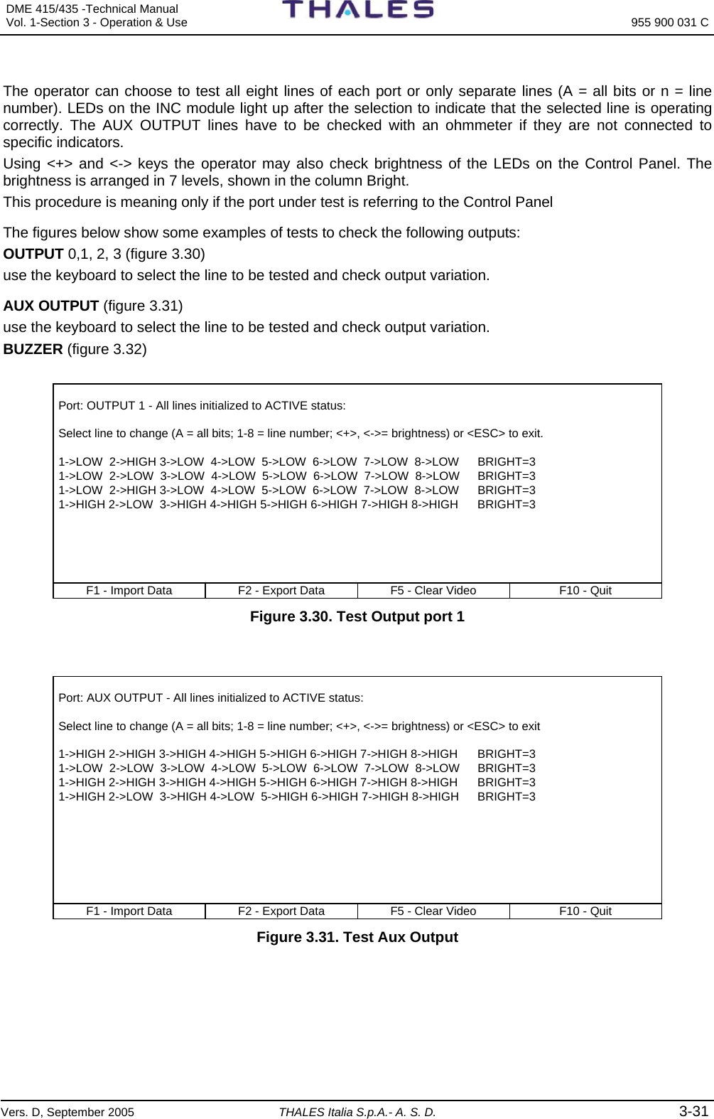
![DME 415/435 -Technical Manual Vol. 1-Section 3 - Operation & Use 955 900 031 C Vers. D, September 2005 THALES Italia S.p.A.- A. S. D. 3-29 3.2.2.3.13 Test of Parallel Input Port Select option [1] on the “Hardware Test” menu to display the page shown in figure 3.25 that is used to test the input ports. LCSU Maintenance Program Test of parallel input port [n] port name [0] CONTROL INPUT [1] AUX INPUT 0..7 [2] AUX INPUT 8..15 [3] ADDITIONAL INPUT 0..3 Select: F1 - Import Data F2 - Export Data F5 - Clear Video F10 - Quit Figure 3.25. Test of Parallel Input Port Some examples of tests that can be made to verify the inputs listed below are shown in the figures that follow: CONTROL INPUT (figure 3.26) The test is performed through the push-buttons on the INC module, which can be found according to the configured arrangement using the procedure described in paragraph 3.2.2.3.3 AUX INPUT (figure 3.27) the test is performed by creating a closure to the common pin, through the pins on connector PL3 of the I/O panel. These can be found according to the configured arrangement using the procedure described in paragraph 3.2.2.3.3. ADDITIONAL INPUT (figure 3.28) the test is performed by creating a closure to the common pin, through the pins on connector PL3 of the I/O panel. These can be found according to the configured arrangement using the procedure described in paragraph 3.2.2.3.3. Port: CONTROL INPUT - Current read line status: 1->LOW 2->LOW 3->LOW 4->LOW 5->LOW 6->LOW 7->LOW 8->LOW Press a key to start status monitor or <ESC> to exit. ** Monitor on input line active ** Changed line number 2 LOW ==> HIGH Changed line number 2 HIGH ==> LOW F1 - Import Data F2 - Export Data F5 - Clear Video F10 - Quit Figure 3.26. Test Control Input](https://usermanual.wiki/Thales-ATM/435.USERS-MANUAL-2/User-Guide-857503-Page-83.png)
![955 900 031 C DME 415/435 -Technical Manual Vol. 1-Section 3 - Operation & Use 3-30 THALES Italia S.p.A.- A. S. D. Vers. D, September 2005 Port: AUX INPUT 0..7 - Current read line status: 1->HIGH 2-> HIGH 3-> HIGH 4-> HIGH 5-> HIGH 6-> HIGH 7-> HIGH 8-> HIGH Press a key to start status monitor or <ESC> to exit. ** Monitor on input line active ** Changed line number 8 HIGH ==> LOW Changed line number 8 LOW ==> HIGH F1 - Import Data F2 - Export Data F5 - Clear Video F10 - Quit Figure 3.27. Test Aux Input Test Aux Input Port: ADDITIONAL INPUT - Current read line status: 1->HIGH 2->HIGH 3->HIGH 4->HIGH 5->HIGH 6->HIGH 7->LOW 8->HIGH Press a key to start status monitor or <ESC> to exit. ** Monitor on input line active ** F1 - Import Data F2 - Export Data F5 - Clear Video F10 - Quit Figure 3.28. Test Additional Input 3.2.2.3.14 Test of Parallel Output Port Select option [2] on the “Hardware Test” menu to display the page shown in figure 3.29 that is used to test the parallel output ports. LCSU Maintenance Program Test of parallel output port [n] port name [0] OUTPUT 0 [1] OUTPUT 1 [2] OUTPUT 2 [3] OUTPUT 3 [4] AUX OUTPUT 0..7 [5] AUX OUTPUT 8..15 [6] ADDITIONAL OUTPUT 0..4 [7] BUZZER Select: F1 - Import Data F2 - Export Data F5 - Clear Video F10 - Quit Figure 3.29. Test of Parallel Output Port](https://usermanual.wiki/Thales-ATM/435.USERS-MANUAL-2/User-Guide-857503-Page-84.png)
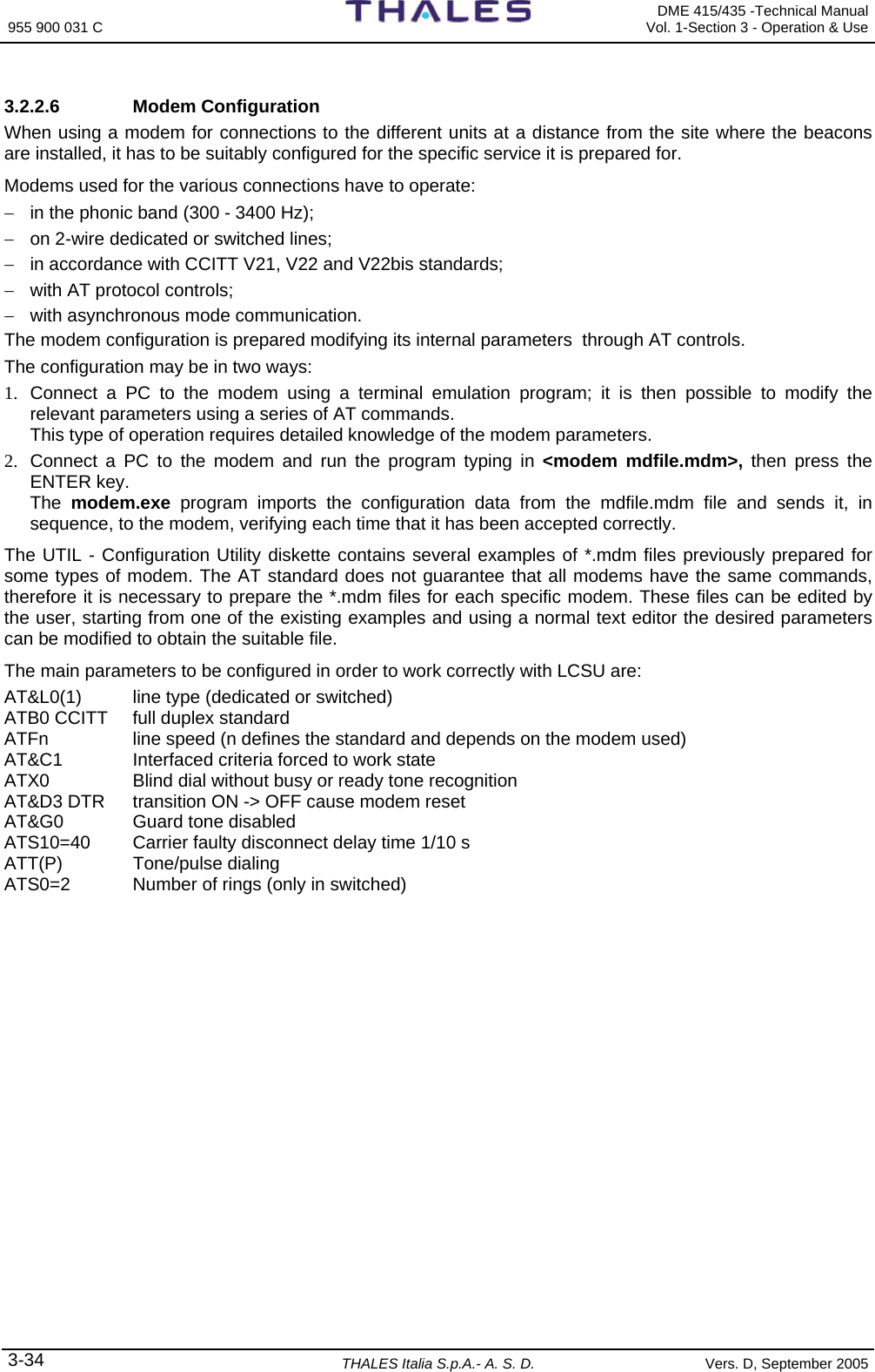
![955 900 031 C DME 415/435 -Technical Manual Vol. 1-Section 3 - Operation & Use 3-32 THALES Italia S.p.A.- A. S. D. Vers. D, September 2005 Port: BUZZER - All lines initialized to ACTIVE (LOW) status: Select line to change (A = all bits; 1-8 = line number; <+>, <->= brightness) or <ESC> to exit 1->HIGH 2->HIGH 3->HIGH 4->HIGH 5->HIGH 6->HIGH 7->HIGH 8->HIGH 1->LOW 2->HIGH 3->HIGH 4->HIGH 5->HIGH 6->HIGH 7->HIGH 8->HIGH 1->HIGH 2->HIGH 3->HIGH 4->HIGH 5->HIGH 6->HIGH 7->HIGH 8->HIGH F1 - Import Data F2 - Export Data F5 - Clear Video F10 - Quit Figure 3.32. Test Buzzer 3.2.2.3.15 Test of Serial Lines Select option [3] on the “Hardware Test” menu to display the page shown in figure 3.33 that is used to perform the tests on serial lines. LCSU Maintenance Program Test of serial lines Serial port number to test (1 to 6): F1 - Import Data F2 - Export Data F5 - Clear Video F10 - Quit Figure 3.33. Test of Serial Lines When the number of the port to be tested is selected, a page is displayed similar to that shown in figure 3.34, that indicates an example of a test on port number 2, for which a modem connection is necessary. Testing port number: 2 Press a key to start emulation or <ESC> to abort ** Emulation program active <ESC>Exit <CTRL-D>Test DTR/DCD Loop ** F1 - Import Data F2 - Export Data F5 - Clear Video F10 - Quit Figure 3.34. Testing of Port Number NOTES − The serial port diagnostics are performed when module CSB on the LCSU is powered on;](https://usermanual.wiki/Thales-ATM/435.USERS-MANUAL-2/User-Guide-857503-Page-86.png)
![DME 415/435 -Technical Manual Vol. 1-Section 3 - Operation & Use 955 900 031 C Vers. D, September 2005 THALES Italia S.p.A.- A. S. D. 3-33 − The request to test port 1 is followed by a message “The emulation port is not testable. Press a key to continue...” since this is the connection port to the PC that the operator is using to dialogue; − For DME equipment the modem 1 and 2 is usually connected to serial port 2 and 3 (PL2 and PL1 of I/O panel); − The functional verification is performed by typing one or more alphanumeric characters from the keyboard, the relevant echo is shown on the PC screen; − The operator must respond to the request to define the baud rate of the modem, if provided on the serial port to be tested: 1 = 300; 2 = 1200 ; 3 = 2400 ; 4 = 4800 ; 5 = 9600; 6 = 19200 − Upon the request message PARITY (N)one, E(ven), O(dd); “N” in other cases. 3.2.2.4 Test Data Consistency To terminate the configuration procedure it is necessary to return to the “Configuration” page and select option [0]. The program then asks the operator whether the configuration data modifications saving procedure is to be performed. The following message will be displayed: “Save configuration changes? (Y/N):” If the reply is “Y” a test is run that can be seen in figure 3.35. If the result is positive, the last line will display the message: “Press a key to start saving.” whereas if the result is negative the previous message is replaced by the indication of the fault found. (E.g.: “E2PROM faulty, data not saved. Press any key to continue..”) The saving operation is indicated by a row of asterisks that appear in sequential order at the end of the operation. Testing data consistency... Testing site code... OK Testing port connection... OK Testing user identification codes... OK Testing buzzer connection... OK Testing control commands equipment connection... OK Testing commands equipment connection... OK Press a key to start saving. F1 - Import Data F2 - Export Data F5 - Clear Video F10 - Quit Figure 3.35. Test Data Consistency 3.2.2.5 To Exit from the Program To exit from the configuration procedure, first return to the “MAIN MENU” and select option [0]. To close the “EMUL.exe” program, press F10 (quit.). Do not forget to select the option [0] of the "Main Menu": the CSB does not leave the configuration program if you press F10 key only. CAUTION](https://usermanual.wiki/Thales-ATM/435.USERS-MANUAL-2/User-Guide-857503-Page-87.png)

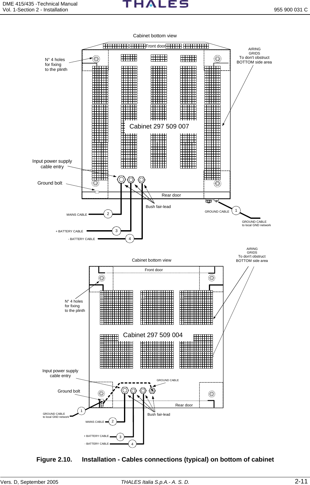
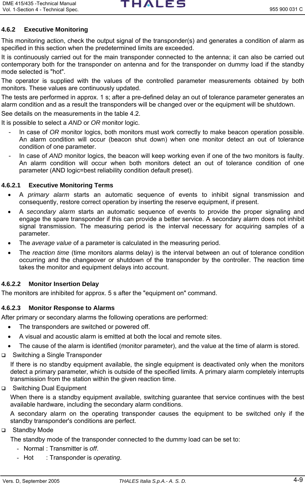
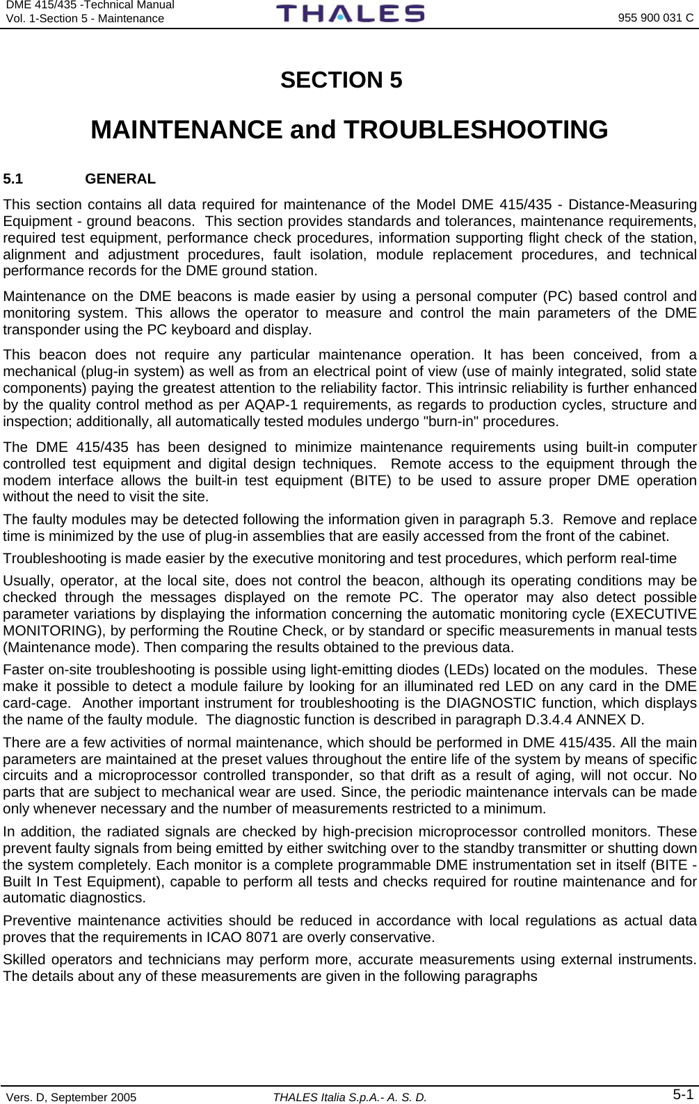
![DME 415/435 -Technical Manual Vol. 1-Section 4 - Technical Spec. 955 900 031 C Vers. D, September 2005 THALES Italia S.p.A.- A. S. D. 4-1 SECTION 4 TECHNICAL SPECIFICATIONS 4.1 GENERAL Equipment DME 415/435 is a ground beacon located in a subrack of 19", equipped with two transponders and a system dual monitoring, microprocessor controlled. This equipment can be also configured like DME/N for 100Wp (DME 415) or 1kWp (DME 435). The following characteristics are valid for the two configurations if that is not specified differently. 4.1.1 Applicable Documents: The DME ground beacons comply with the following specifications: − ICAO Annex 10, 5th edition, International Standard and Recommended Practices − EUROCAE ground DME, MPS (Minimum Performance Specification), ed.57, Iss. December 1986. − C E directives for Transceiver ETS 300 339 (EMC) EN 60065 – EN6215 (Safety) − EEC Directives for CE marking: EMC/89/336 Electrical Safety/73/23. 4.2 ENVIRONMENTAL AND SERVICE CONDITIONS The optimal environmental conditions for beacon operation are given below: − Temperature operation indoor: from −10°C to +55 °C. − relative humidity: up to 95% (-10 to +35°C); max 60% (> 35°C); − pressure: from 760 to 500 millimeters of mercury from sea level to an altitude of approximately 3000 meters; if the equipment is to be installed on sites at even greater altitudes, consult the manufacturer. As regards beacon storage and transport, the temperature must be within the limits −40 °C and +70 °C and pressure up to 15000 m. 4.3 PHYSICAL CHARACTERISTICS The beacon physical characteristics of the equipment single 19" standard cabinet are as follows: − height: 1730 mm; − width: 580 mm; − depth: 610 mm (cabinet code 297 509 004); 635 mm (cabinet code 297 509 007) ; − weight: approx. 145 kg DME 415 (optional modules included). approx. 165 kg DME 435 (optional modules included) Completely modular with plug-in module type. Plug-in units are used as double or single Euroform printed multi-layer circuit boards, with dimensions of 233.4 x 220 [mm] or 100 x 220 [mm] accommodate on four subracks (full version). The RF modules are accurately shielded in casting boxes.](https://usermanual.wiki/Thales-ATM/435.USERS-MANUAL-2/User-Guide-857503-Page-103.png)
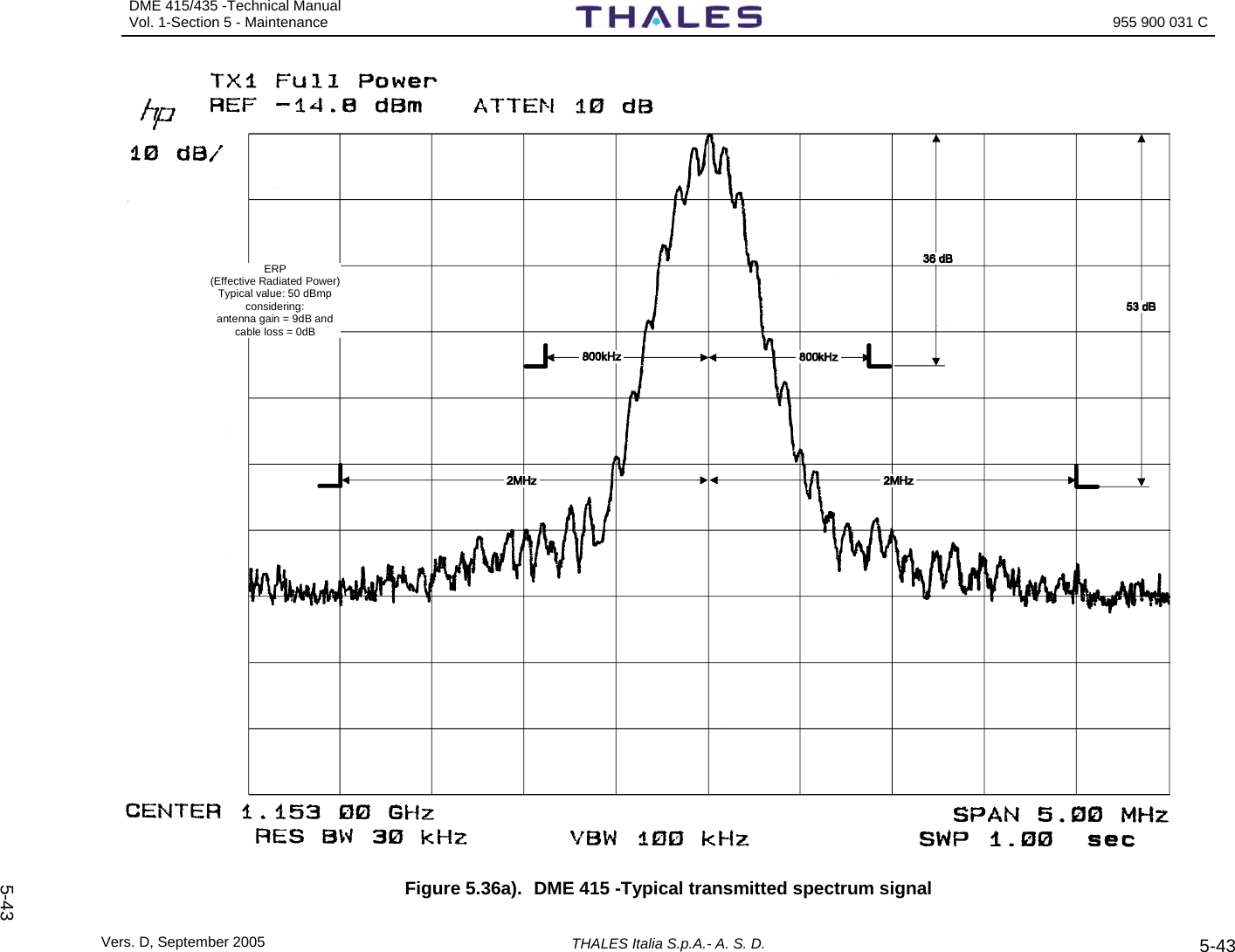
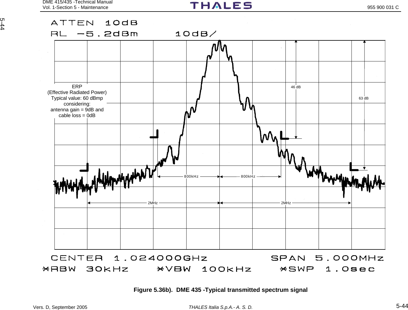
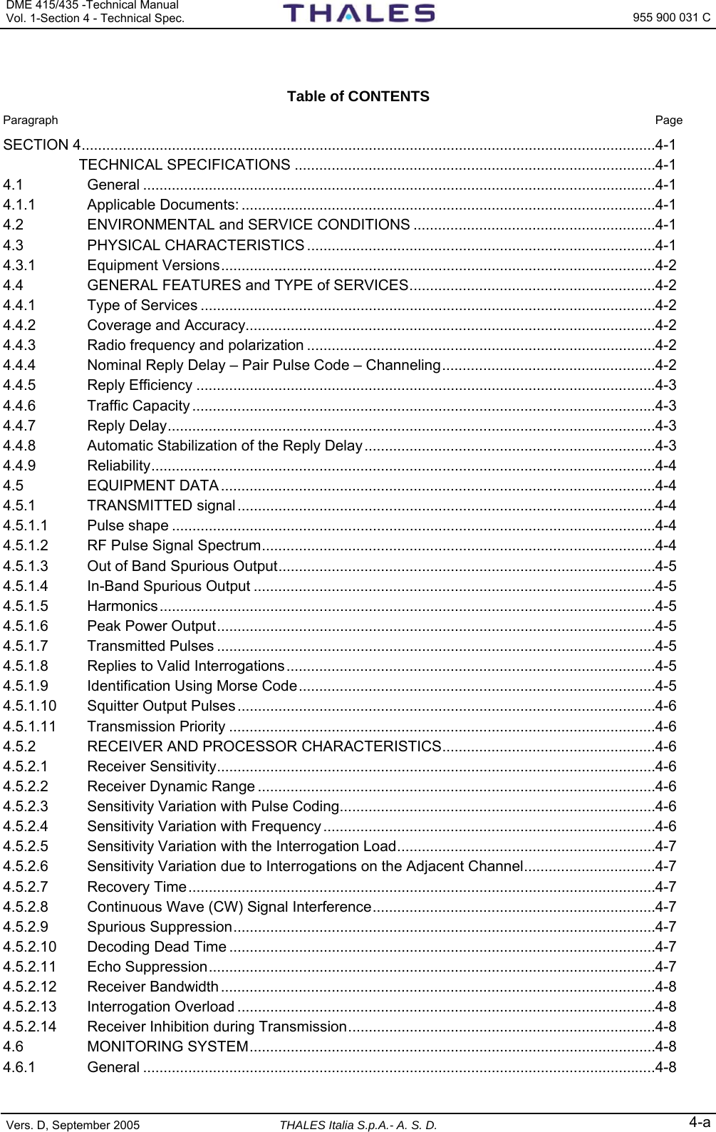
![DME 415/435 -Technical Manual Vol. 1-Section 4 - Technical Spec. 955 900 031 C Vers. D, September 2005 THALES Italia S.p.A.- A. S. D. 4-3 Table 4.1 Channel code, pulse code, reply delay CHANNEL CODE NOMINAL INTERROGATION PULSE PAIR SPACING CODE [µs] TRANSPONDER REPLY PULSE PAIR SPACING CODE [µs] TRANSPONDER NOMINAL REPLY DELAY [µs] X 12 12.0 ± 0.1 50 Y 36 30.0 ± 0.1 56 4.4.5 Reply Efficiency The Reply Efficiency is better than 70% and internal noise not cause more than 10 pair transmission/s 4.4.6 Traffic Capacity The DME beacon is always capable of giving distance information to a maximum of 200 interrogating airborne equipment. It is however, possible to select two transmissions rates values: ranging from 800 to 4800 ppps or ranging from 2700 to 4800 ppps. The difference is given by the minimum number of pulse pairs per second (800 ±50 ppps or 2700 ±90 ppps) transmitted by the equipment. Even in case of no interrogations from the airborne interrogators; as a result, the power consumption will be different. 4.4.7 Reply Delay The reply delay may be defined as the reply interval between an interrogation, in antenna, and the corresponding reply at the same point. On a DME/N beacon, the reply delay may be selected in 0.05 µs steps, as follows: - from 35 µs to 75 µs for X channels; - from 50 µs to 75 µs for Y channels. As far as reply delay accuracy according to interrogation level is concerned: Interrogation level delay variation (average) distance accuracy (average typical) from –10 dBm to –79 dBm ± 0,2 µs ± 30 m from –79 dBm to –89 dBm ± 0,4 µs ±60 m from –89 dBm to –91 dBm ± 0,6 µs ±90 m 4.4.8 Automatic Stabilization of the Reply Delay The reply delay can be automatically adjusted according to the measurements performed by the monitors and of specific circuits on the transponder (circuits of pilot pulse) that they measure and they adjourn the precision of the reply delay in continuity with step of 12,5ns. The average value of the measurements from both monitors is used to modify the reply delay presetting in steps of 12,5 ns. The automatic reply delay stabilization will continue even if one of monitors is faulty, if the monitoring logic set will permitted.](https://usermanual.wiki/Thales-ATM/435.USERS-MANUAL-2/User-Guide-857503-Page-105.png)


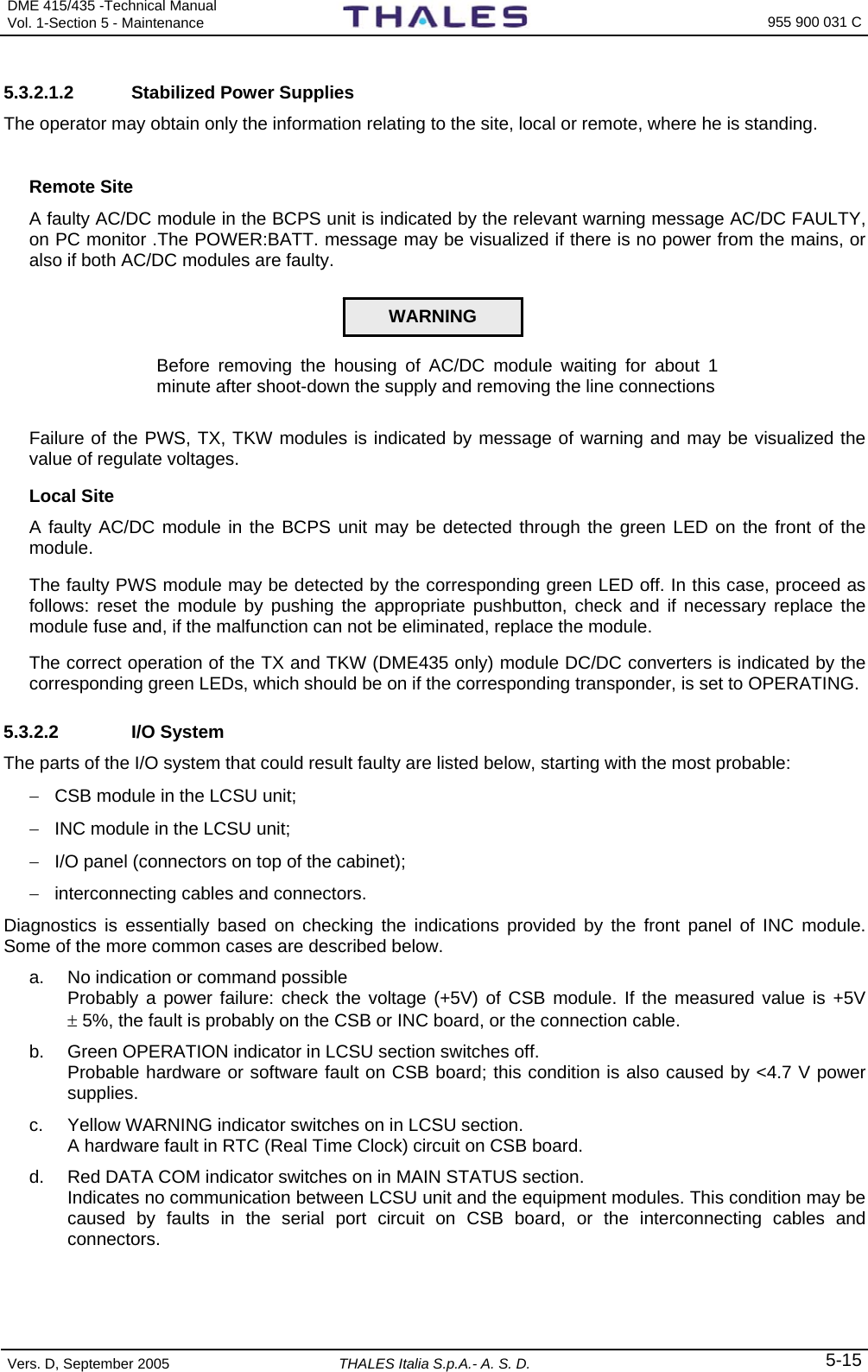
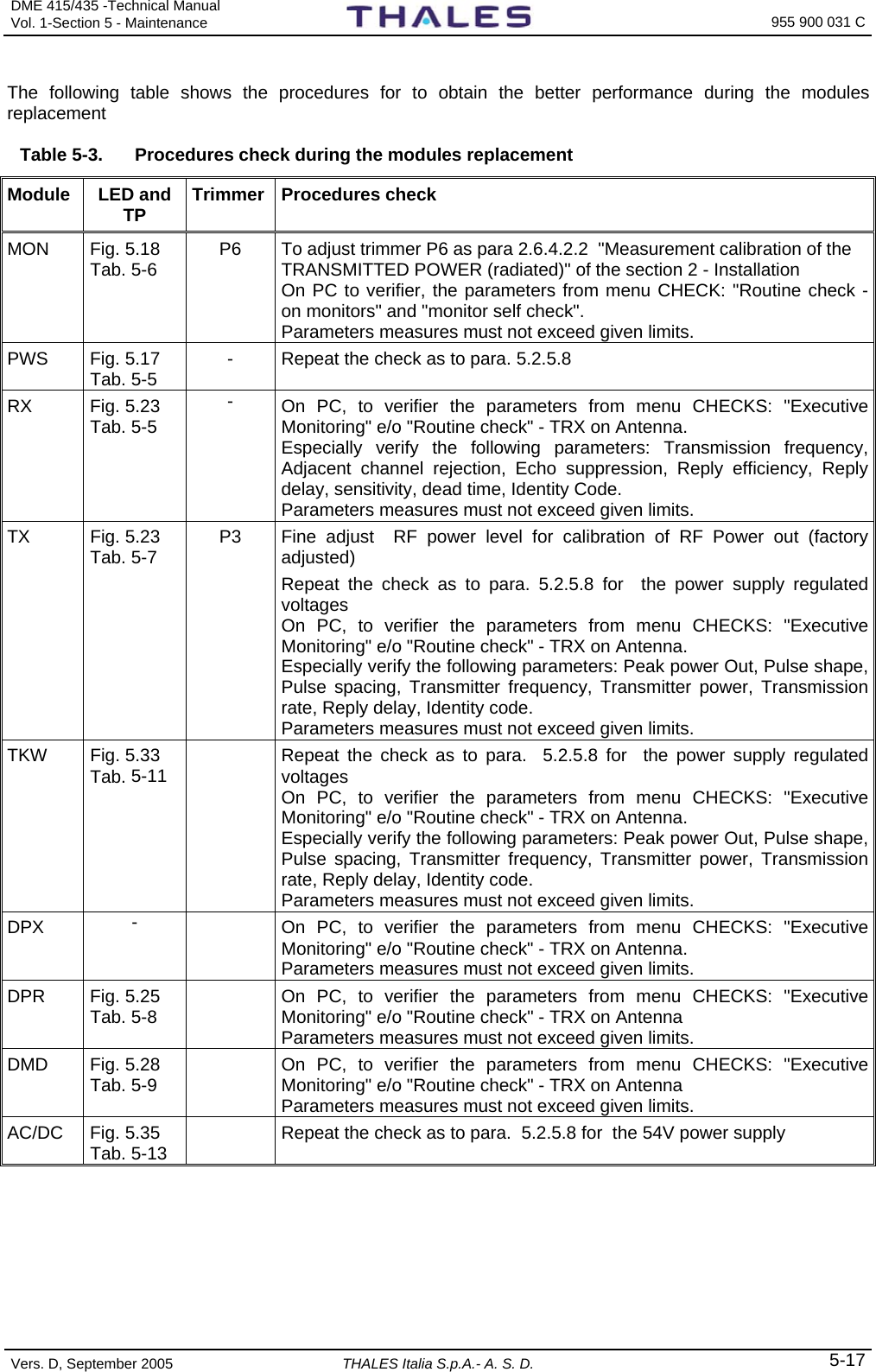
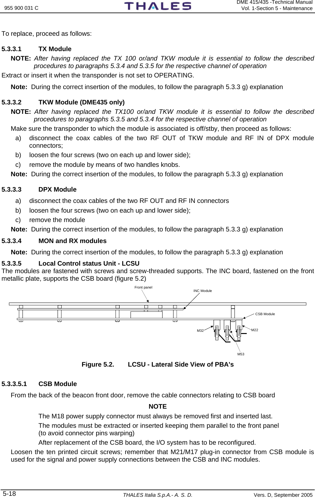
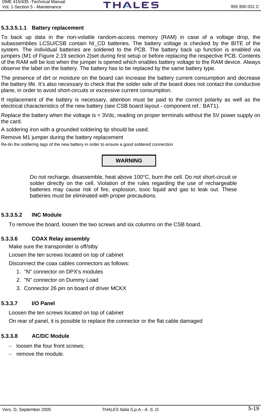
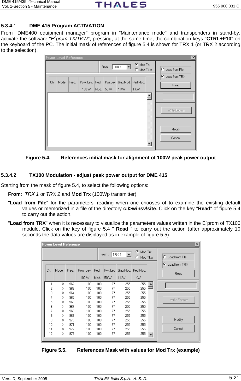
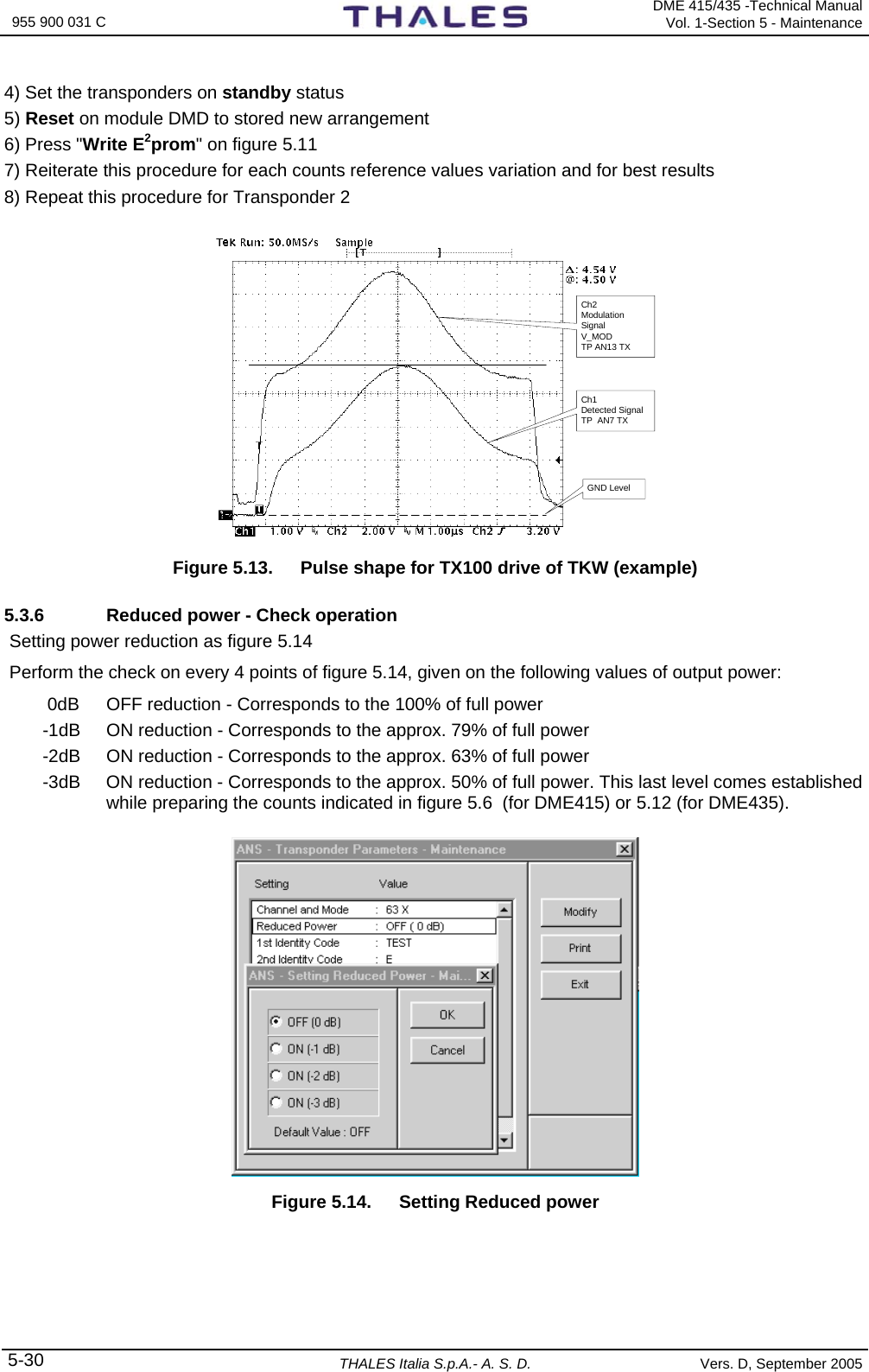
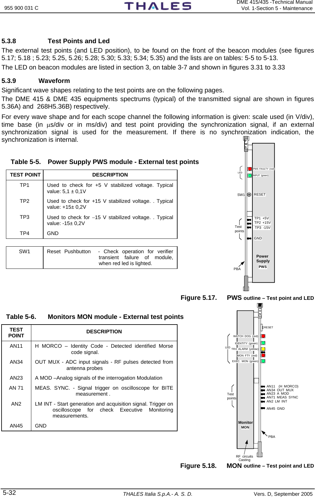
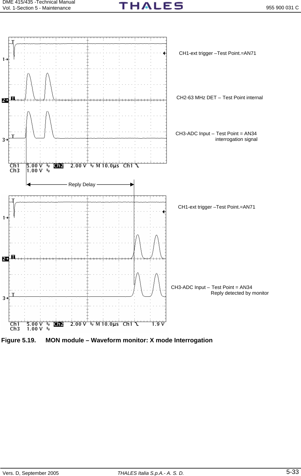
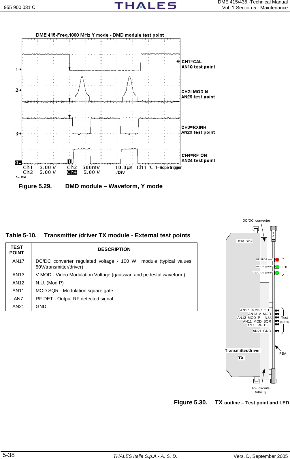
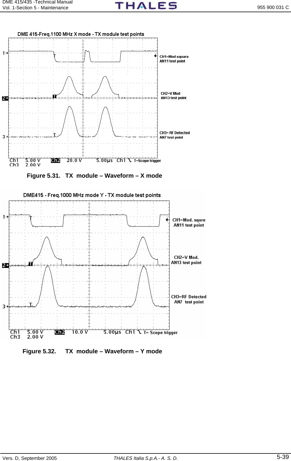
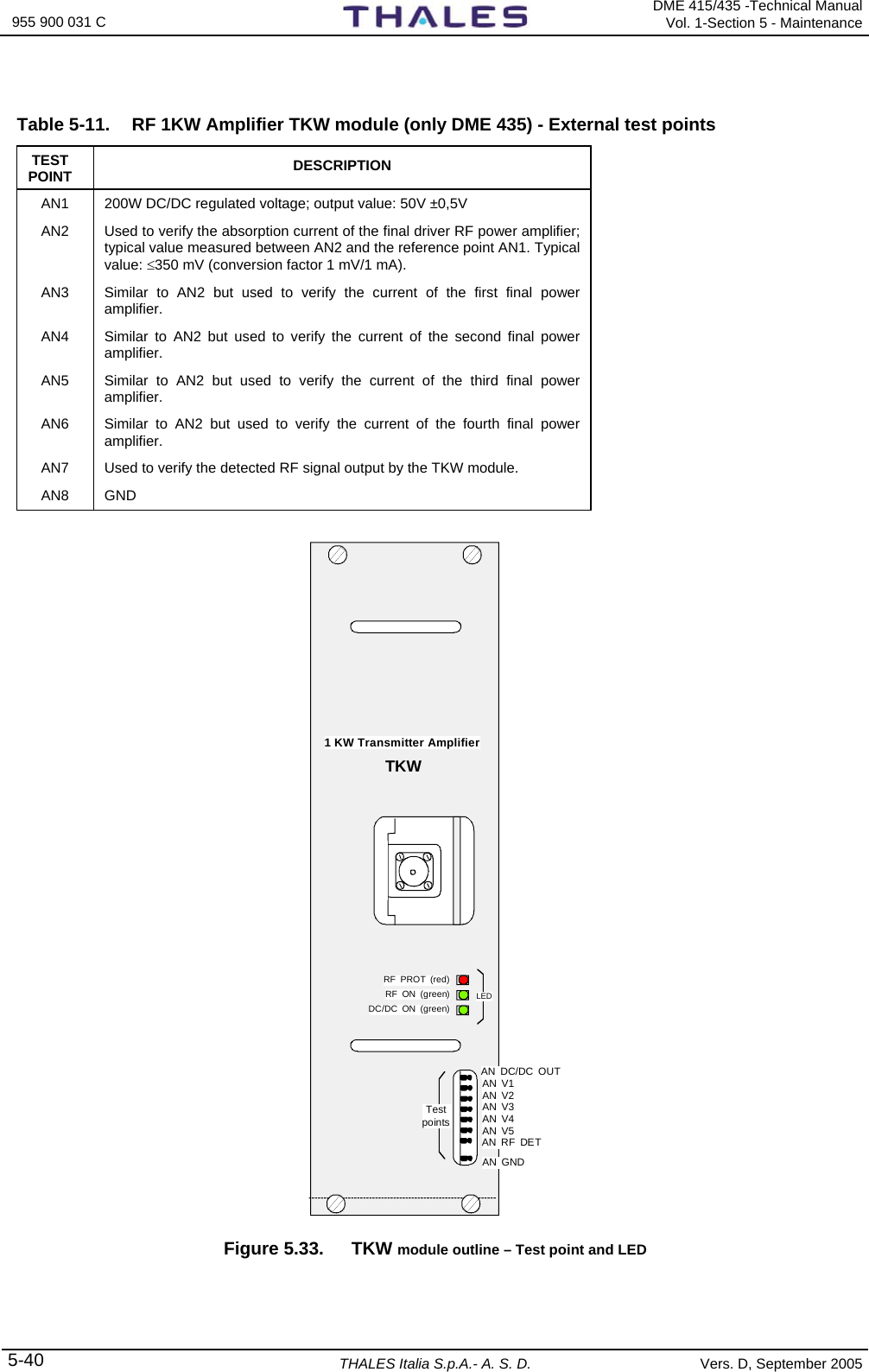
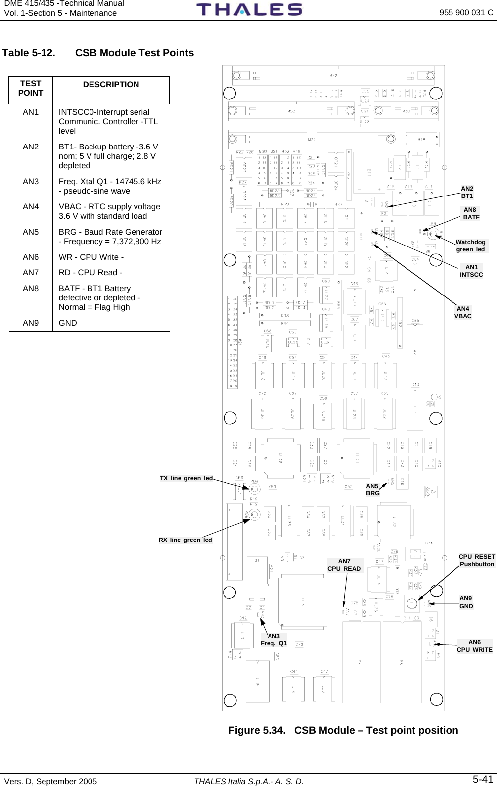
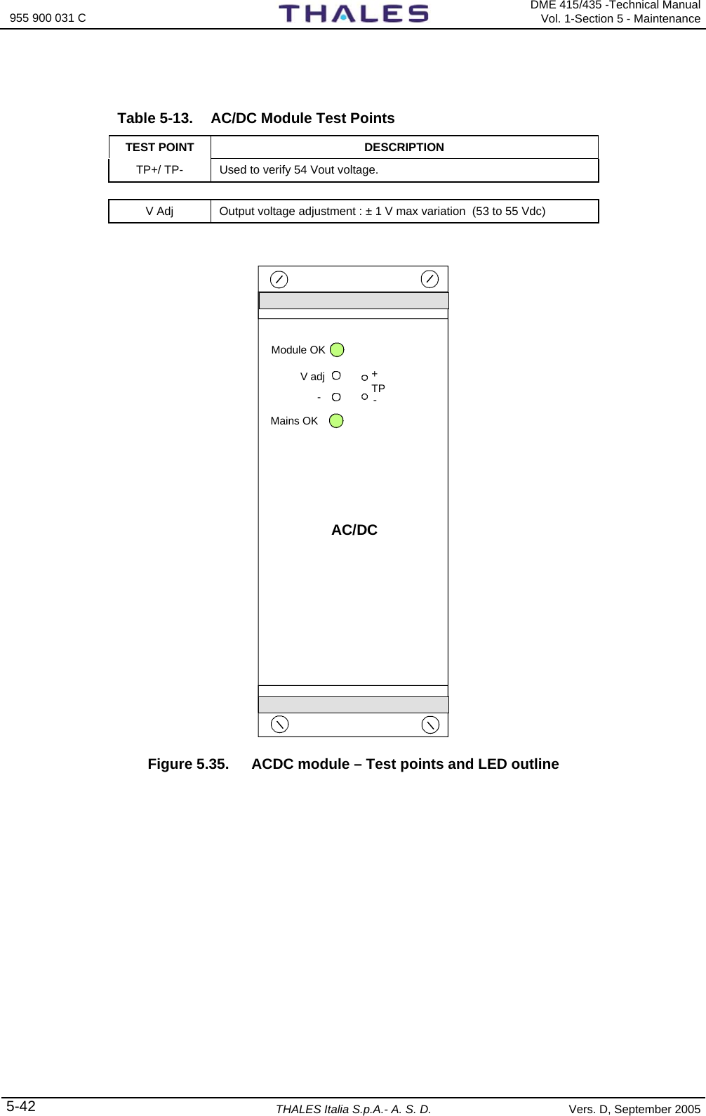
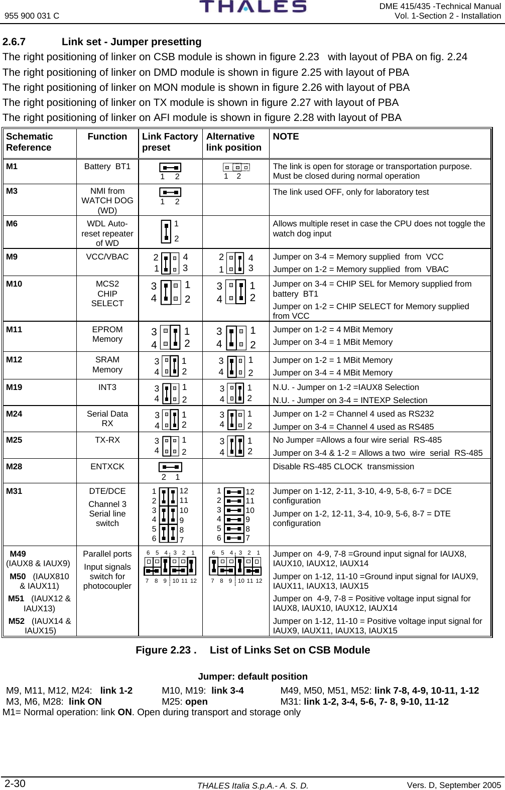
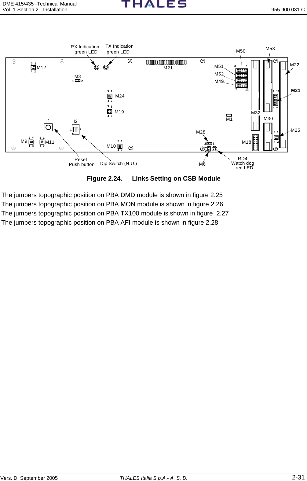
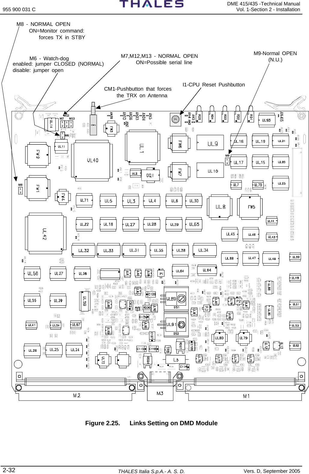
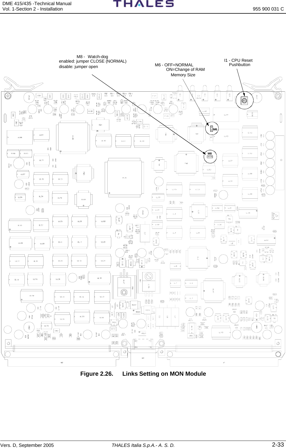
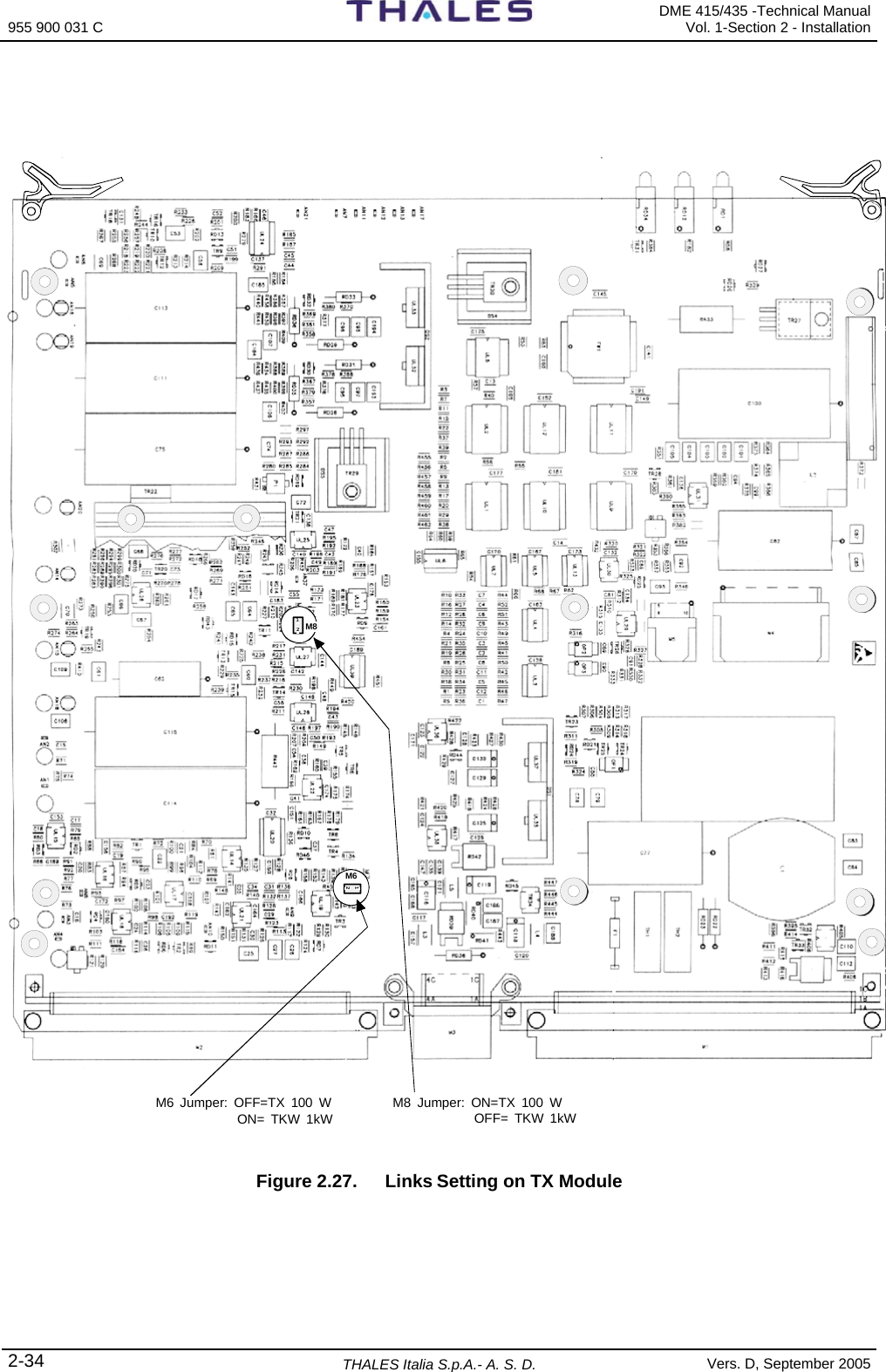
![955 900 031 C DME 415/435 -Technical ManualVol. 1-Section 5 - Maintenance 5-16 THALES Italia S.p.A.- A. S. D. Vers. D, September 2005 Before replacing the CSB board, make these two tests: a. Press the LAMP TEST pushbutton located in the LCSU section and verify the indicators are working properly. b. Shut down all the equipment from the control panel then switches on again after a few seconds. If the fault persists, replace the CSB board since the failure is not caused by a transient fault condition. The INC board can be indirectly tested through the LAMP TEST. By verifying that the individual indicators and buzzers are operating and using the control push-buttons, check they are working efficiently. If the indications and commands are correct on the PC and the corresponding indications are different on the INC module, there may be an INC board fault or the configuration made is not correct. The serial and parallel ports I/O can be checked by verifying the ON/OFF levels using the Hardware Test described in section 3 in this volume; item [3] of the main menu displays the HARDWARE TEST command that can be used to test all the parallel line inputs and outputs and all the serial channels either separately or in groups. Cable or connector faults are unlikely to occur. When they are present, a visual inspection will often indicate where a cable has been damaged. 5.3.3 Modules Replacement Procedures a) All the modules may be removed and installed without removing power. The special design of the connector that supplies power to each module prevents damage to the electronics from occurring. b) Modules replacement is made easier thanks to the plug-in technique and to the upper and lower extractors every module. To extract these modules, lift the extractors (push them towards the inside of the beacon) and pull the module out of its guides. To reconnect the module, reinsert it back in its guides, push it in and lower the extractors. c) Several of the modules have jumper switches on their printed circuit boards. It is essential to check that the switches or jumpers on the new PBA are set to the same positions as on the old module. Section 2 "INSTALLATION" contains the list of the jumpers. d) Modules with extractors do not require any special operations for their replacement, except for the DPX and TKW modules, which requires unscrewing the proper front screws and coax. cables disconnection. e) Outline drawing are shown in this section f) For other modules, not proved with extractors and requiring particular procedures, proceed as described below. g) The specific RF connectors plug-in, situate at the back panel and associated to semi-rigid coax cables, must be fixed in sure way from the proper nut, by using the spanner of 16 mm. They must have little end clearance to help the insertion system. On each removed module, to check and regulate manually that each RF connector on the back panel are under the previously mentioned conditions. The modules interested at these notes are RX, MON, DPX, TX100 and TKW. Connectors SMA must be fixed with the torque wrench (1Nm/8.9in-lbs) code 870952302X. You have this spanner in the tool bag of the equipment. Connectors "N" of coax cables, must be screwed and blocked in sure way. NOTES: Check that all the RF cables have been connected correctly before switching the transmitter on again, and make sure that either the antenna or a dummy load is connected On some modules are scheduled opportune trimmers that are factory adjusted: they must not be tampered with, if the maximum precision of system wants to be obtained. After having replaced the TX100 or/and TKW module it is essential to follow the described procedures to paragraphs 5.3.5 and 5.3.4 for the respective channel of operation](https://usermanual.wiki/Thales-ATM/435.USERS-MANUAL-2/User-Guide-857503-Page-142.png)