Thales ATM 435 LICENSED NON-BROADCAST TRANSMITTER User Manual USERS MANUAL 2
Thales ATM LICENSED NON-BROADCAST TRANSMITTER USERS MANUAL 2
Contents
- 1. USERS MANUAL 1
- 2. USERS MANUAL 2
USERS MANUAL 2

THALES Italia S.p.A.- Air Systems Division
-
Description, Installation, Operation, Maintenance Reference: Vol. 1 Code 955 900 031 C
GROUND BEACON
DME 415/435
Technical Manual
VOLUME 1
Equipment description, Installation, Operation, Maintenance and PC user
Vers. D, September 2005
SECTION 2
INSTALLATION

955 900 031 C DME 415/435 -Technical Manual
Vol. 1-Section 2 - Installation
2-II THALES Italia S.p.A.- A. S. D. Vers. D, September 2005

DME 415/435 -Technical Manual
Vol. 1-Section 2 - Installation 955 900 031 C
Vers. D, September 2005 THALES Italia S.p.A.- A. S. D. 2-a
Table of CONTENTS
Paragraph Page
SECTION 2 ...........................................................................................................................................2-1
INSTALLATION...................................................................................................................2-1
2.1 General installation information........................................................................................2-1
2.1.1 Safety Precautions ...........................................................................................................2-1
2.1.1.1 General rules ....................................................................................................................2-1
2.2 INSTALLATION PRELIMINARY.......................................................................................2-2
2.3 INSTALLATION SITE SELECTION..................................................................................2-2
2.4 EQUIPMENT SITE LOCATION........................................................................................2-3
2.5 UNPACKING, PACKING AND SHIPPING;......................................................................2-3
2.6 Typical INSTALLATION....................................................................................................2-3
2.6.1 Installation cables .............................................................................................................2-4
2.6.2 Grounding.........................................................................................................................2-8
2.6.3 Power supply connection..................................................................................................2-8
2.6.3.1 Batteries............................................................................................................................2-13
2.6.3.1.1 Battery duration time (on 230Vac black-out)....................................................................2-13
2.6.4 ANTENNA CONNECTION ...............................................................................................2-14
2.6.4.1 Antenna coax cables-Attenuations and delays ................................................................2-15
2.6.4.2 Data entry calibration procedure for “EXTENDED CONFIGURATION”...........................2-15
2.6.4.2.1 Check of the OUTPUT POWER measurement on transponder ......................................2-17
2.6.4.2.2 Measurement calibration of the TRANSMITTED POWER (radiated) ..............................2-17
2.6.5 Adjustment Power Reading by monitor............................................................................2-19
2.6.6 I/O and external interface connections.............................................................................2-20
2.6.7 Link set - Jumper presetting .............................................................................................2-30
2.6.8 Associated Facility Interface.............................................................................................2-35
2.6.9 Remote Control and Status Indicator ...............................................................................2-41
2.6.10 PC Installation...................................................................................................................2-42
2.6.11 Power supply with BCPS subrack of Frako type (optional version) .................................2-43
2.6.11.1 External power supply 48Vdc connection (Frako subrack) ..............................................2-43
List of FIGURES
Figure Page
Figure 2.1. AUX OUT I/O cable ........................................................................................................2-4
Figure 2.2. AUX IN I/O cable ............................................................................................................2-5
Figure 2.3. PC serial cable ...............................................................................................................2-5
Figure 2.4. RS232 External Modem cable........................................................................................2-6
Figure 2.5. Interface Facility cable....................................................................................................2-6
Figure 2.6. RF coax cable - LCF 1/2" ...............................................................................................2-7
Figure 2.7. Obstruction light cable....................................................................................................2-8
Figure 2.8. Installation connections (typical) ....................................................................................2-9
Figure 2.9. Installation - Cables connections (typical) on top end of equipment..............................2-10
Figure 2.10. Installation - Cables connections (typical) on bottom of cabinet ....................................2-11
Figure 2.11. Cable connection - Grounding and AC power supply of the Terminal Bar ....................2-12
Figure 2.12. Cables connection - Grounding and AC power supply .................................................2-12

955 900 031 C DME 415/435 -Technical Manual
Vol. 1-Section 2 - Installation
2-b THALES Italia S.p.A.- A. S. D. Vers. D, September 2005
Figure Page
Figure 2.13. Grounding and external 48 Vdc power supply - Cables connection.............................. 2-13
Figure 2.14. Battery connections typical ............................................................................................ 2-13
Figure 2.15. Cable connections to FAN 96 antenna .......................................................................... 2-14
Figure 2.16a. Simplified diagram of Antenna coax cables................................................................... 2-16
Figure 2.16b. “EXTENDED CONFIGURATION” – Example of data entry .......................................... 2-16
Figure 2.17. MON module – Trimmer adj. position of the “Transmitted Power” measurement......... 2-18
Figure 2.18 Screen of correct measurement by Monitor 1 & 2 ......................................................... 2-19
Figure 2.19 Screen of configuration for power reading adjustment .................................................. 2-19
Figure 2.20. I/O panel, top view ......................................................................................................... 2-21
Figure 2.21. Parallel Input Lines application ...................................................................................... 2-28
Figure 2.22. Parallel Output Lines application ................................................................................... 2-29
Figure 2.23 . List of Links Set on CSB Module ................................................................................... 2-30
Figure 2.24. Links Setting on CSB Module ........................................................................................ 2-31
Figure 2.25. Links Setting on DMD Module ....................................................................................... 2-32
Figure 2.26. Links Setting on MON Module ....................................................................................... 2-33
Figure 2.27. Links Setting on TX Module........................................................................................... 2-34
Figure 2.28. Header plugs setting on AFI Module.............................................................................. 2-36
Figure 2.29. AFI Module - Input and output signals application......................................................... 2-37
Figure 2.29a. AFI Module – Association example with VOR/ILS 400.................................................. 2-38
Figure 2.29b. AFI Module – Association example with VOR/ILS NORMAC........................................ 2-39
Figure 2.30. Equipment associated examples ................................................................................... 2-40
Figure 2.31. Remote Control and Status Indications connection examples ...................................... 2-41
Figure 2.32. PC connection examples ............................................................................................... 2-42
Figure 2.33. BCPS subrack of Frako type - Supply cables connection ............................................ 2-43
List of TABLES
Table Page
Table 2-1 - List of typical installation cables......................................................................................... 2-4
Table 2-2 - RF coax cable LCF 1/2" CU2Y type - Technical specification........................................... 2-7
Table 2-3 - STD Coax cables ............................................................................................................... 2-15
Table 2-4 - Loss of STD coax cables ................................................................................................... 2-17
Table 2-5 - Monitors power alarm threshold examples ........................................................................ 2-18
Table 2-6a - SK1 on I/O panel and front panel - Serial Ports PC connector pin-out signals ............... 2-21
Table 2-6b - PL1 and PL2 on I/O panel - Serial Ports MDM connector pin-out signals....................... 2-22
Table 2-7a - PL3 on I/O panel - INPUT Parallel Port Connector pin-out signals ................................. 2-23
Table 2-7b - SK2 on I/O panel - OUTPUT Parallel Port Connector pin-out signals............................. 2-24
Table 2-7c - PL4 on I/O panel (optional) - INPUT Parallel Port connector pin-out signals.................. 2-25
Table 2-7d - SK3 on I/O panel (optional) - OUTPUT Parallel Port Connector pin-out Signals ............ 2-26
Table 2-8 - PL7 on I/O Panel - Telephone line Connector pin-out signals........................................... 2-27
Table 2-9 - SK4 and SK5 on I/O Panel - AFI Connectors pin-out signals........................................... 2-27
Table 2-10 - AFI Connectors pin-out signals........................................................................................ 2-35

DME 415/435 -Technical Manual
Vol. 1-Section 2 - Installation 955 900 031 C
Vers. D, September 2005 THALES Italia S.p.A.- A. S. D. 2-1
SECTION 2
INSTALLATION
2.1 GENERAL INSTALLATION INFORMATION
2.1.1 Safety Precautions
It is the task of the site supervisor or construction manager to make available the materials supplied by
THALES Italia s.p.a., independently procured special materials and tools. For every site, strict attention
should be paid to safety regulations issued by the local authorities.
2.1.1.1 General rules
The following rules should be observed for prevention of accidents:
- Consumption of alcohol in any form is forbidden on the installation site.
- Drunken persons or those under influence of alcohol will not be tolerated on the installation site.
- Protective goggles and safety gloves are to be worn when work is being carried out on batteries. Rinsing
water, soda and several cleaning cloths should be available.
- Sturdy shoes, safety gloves and safety helmets are to be worn.
- Protruding nails, strips etc. must be removed immediately. Ladders and planks must always be carefully
checked before use.
- Do not tread on protruding plank sections.
- Never leave objects on scaffolding or ladders.
- Scaffolding or frames are to be erected sturdily and must always be tested before use.
- Test electrical devices and extension cables for accident safety.
- Remove fuses before carrying out work on mains.
- Wear protective goggles when carrying out sanding or drilling operations.
- Sand off burr from chisels and punches in good time.
- Test striking tools for tightness of fit.
- Do not put pointed or sharp objects into working-clothing pockets.
- Jewelry such as chains and rings should be removed when working on building sites - especially when
working with electrical devices.
- Always keep escape routes clear.
- Every employee on an installation site should know:
• where the First-Aid box is kept
• the telephone number of the nearest casualty doctor and eye specialist
• where the fire extinguisher is kept
• the location of hazardous areas on the way to the work place, or at the work place itself.
Damage caused by animals is highly improbable. The door of the shelter or equipment room should be
locked in the absence of the personnel.

955 900 031 C DME 415/435 -Technical Manual
Vol. 1-Section 2 - Installation
2-2 THALES Italia S.p.A.- A. S. D. Vers. D, September 2005
2.2 INSTALLATION PRELIMINARY
The operator must perform the following operations when installing the beacon:
Select and prepare the site;
Unpacking, Paging and shipping;
Typical installation
• ground the equipment;
• connect the power supplies;
• connect the antenna.
• I/O connections
The following connections may also be necessary, depending on the beacon configuration selected
and the options used:
• connection the facility with associated equipment;
• connection with other equipment.
2.3 INSTALLATION SITE SELECTION
The area in which a DME is to be installed is determined by the responsible Civil Aviation Authority
according to the international air traffic regulations.
The area is dependent on the type of obstacle. Also clearance and runway configuration (e.g. overrun,
clearway, stopway) in case located in terminal area.
The following site selection guidelines are general recommendation and only guiding values for information.
The exact values are locally dependent decisions, which are made during installation. They are computed
with formulas, which take in account of terrain, obstacles and other. See Appendix "A – DME Antenna Siting
Area Criteria", on this volume.
The installation is determined by means of a site survey at which a surveyor must always be present.
THALES Italia s.p.a. is able to provide engineering consultants on site for this survey.
The DME installation area selection depends on the following using conditions:
1) Terminal Area beacon
a) DME (substituting or integrating MARKER functions) placed with ILS equipment
In this case, DME antenna, usually directional antenna, is mounted on Glide Slope antenna mast
and the DME equipment is installed into Glide Path shelter.
b) Stand-alone
DME with omnidirectional antenna on its own mast and equipment installed into a suitable
shelter. The area is dependent on clearance and runway configuration.
2) In route beacon
(External zone site and normally far away from terminal area), with or without associated VOR
equipment: see Appendix "A – DME Antenna Siting Area Criteria", on this volume

DME 415/435 -Technical Manual
Vol. 1-Section 2 - Installation 955 900 031 C
Vers. D, September 2005 THALES Italia S.p.A.- A. S. D. 2-3
2.4 EQUIPMENT SITE LOCATION
The ground beacon may be installed in a control room or inside a shelter, which complies with the
environmental temperature, humidity and pressure values listed in Section 4. Bear in mind that the
equipment has the following overall dimensions:
− height: 1730 mm,
− width: 580 mm,
− depth: 635 mm cabinet code 297509007or 610 mm cabinet code 297509004
the amount of space around the equipment must be as follows:
− more than a value between the rear part of the beacon and the wall or any other piece of equipment, to
allow the operator to open the rear door of the equipment.
Make it possible support the back part of the cabinet to a wall, in as all the operations of cables and
connectors assemblage, could be performed on front.
− a minimum of 30 cm between the top of the beacon and the ceiling of the control room or the shelter to
leave space for the external connection cables and to allow access to the antenna connector and to the
antenna probes connectors;
− a minimum of 60 cm between the front of the beacon and the wall or any other piece of equipment, to
allow the operator to open the front door.
The base must be able to support the total weight of the equipment (approx. 200/230 kg including the
optional modules) within the range of dynamic stress envisaged for the equipment.
The beacon does not normally need securing; if it is to be secured to the base, however, four M12 bolts
should be used and their fixing holes.
2.5 UNPACKING, PACKING AND SHIPPING;
The equipment should be unpacked as soon as possible in order to check that it is complete and intact. The
place of storage used for any intermediate storage period must be dry. The temperature range specified in
the technical data section 4 must be conformed to. The check list is inside the packing to which to refer.
The DME beacon and modules will be packed according to the national and international standards. The
packing procedure may be slightly different according to the way of shipping or to the destination country.
2.6 TYPICAL INSTALLATION
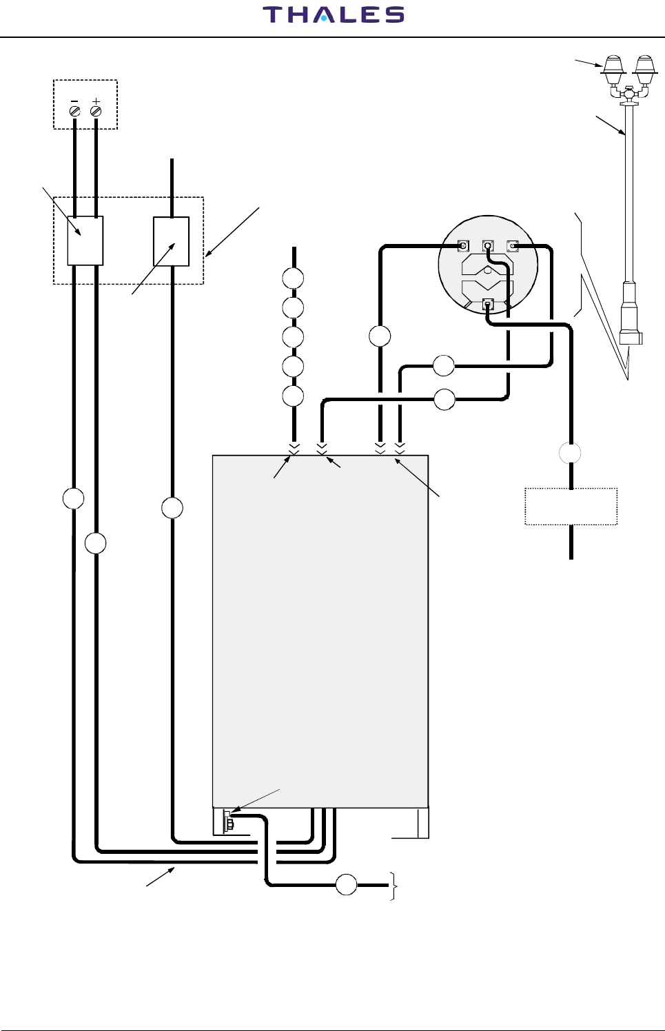
Figure 2.8 shows all the connections for beacon installation. Should this use an I/O system provided with the
LCSU unit in standard configuration; this figure also illustrates the characteristics of the cables used for
installation and provided by the manufacturer, as listed in table 2.1. The main characteristics of installation
cables are on figures 2.1 to 2.7. The reference item is shown on figures, internal at a circle.
WARNING
Before connecting the cables check that the mains lead is dead and that the battery is not
connected (the breaker of mains and battery, on external electrical switchboard, must be OFF).
955 900 031 C DME 415/435 -Technical Manual
Vol. 1-Section 2 - Installation
2-4 THALES Italia S.p.A.- A. S. D. Vers. D, September 2005
2.6.1 Installation cables
. The main characteristics of installation cables are on figures 2.1 to 2.7. and in table 2-1.
Table 2-1 - List of typical installation cables
REF. CABLE LENGTH
(m) NOTE
1 GROUND CABLE (option) 15 Single wire section:25 mm2. External wire
covering: Ø=11 mm, green/yellow color
2 MAINS POWER SUPPLY CABLE (option) 15 Three wires section 2,5mm2 each – External
cable covering Ø=15,2 mm
3 BATTERY CABLE (RO) (option) 15 Single wire section:10 mm2 -
External wire covering: Ø=7,6 mm; red color
4 BATTERY CABLE (NE) (option) 15 Single wire section:10 mm2 -
External wire covering Ø=7,6 mm; black color
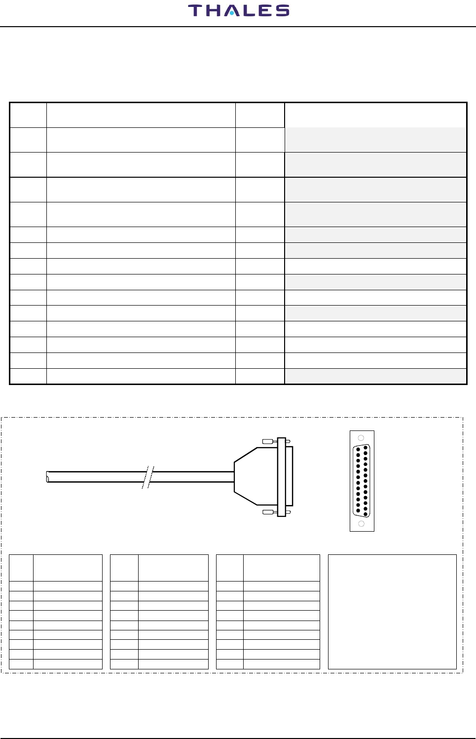
5 AUX OUT I/O CABLE (option) 10 see figure 2.1
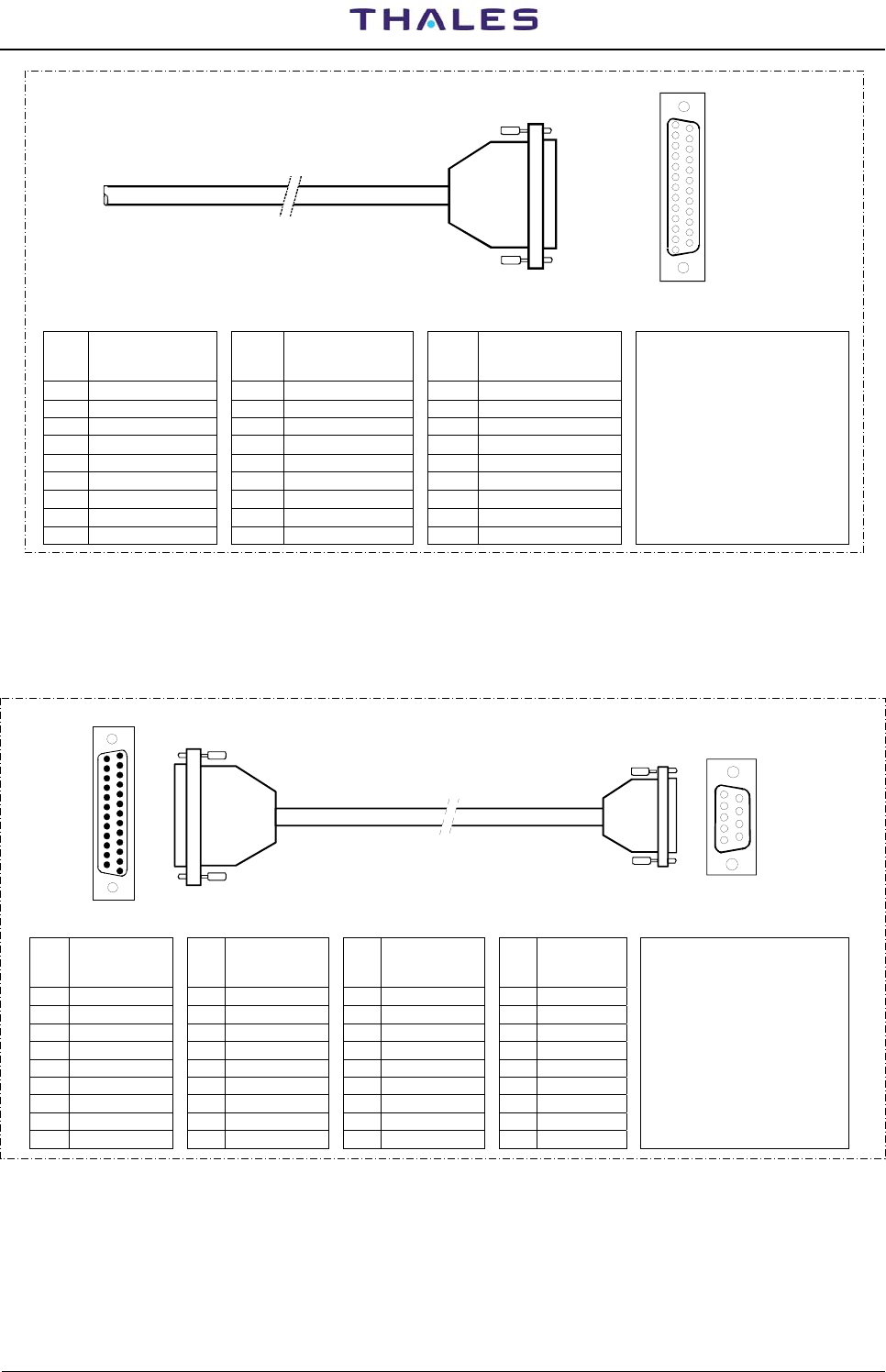
6 AUX IN I/O CABLE (option) 10 see figure 2.2
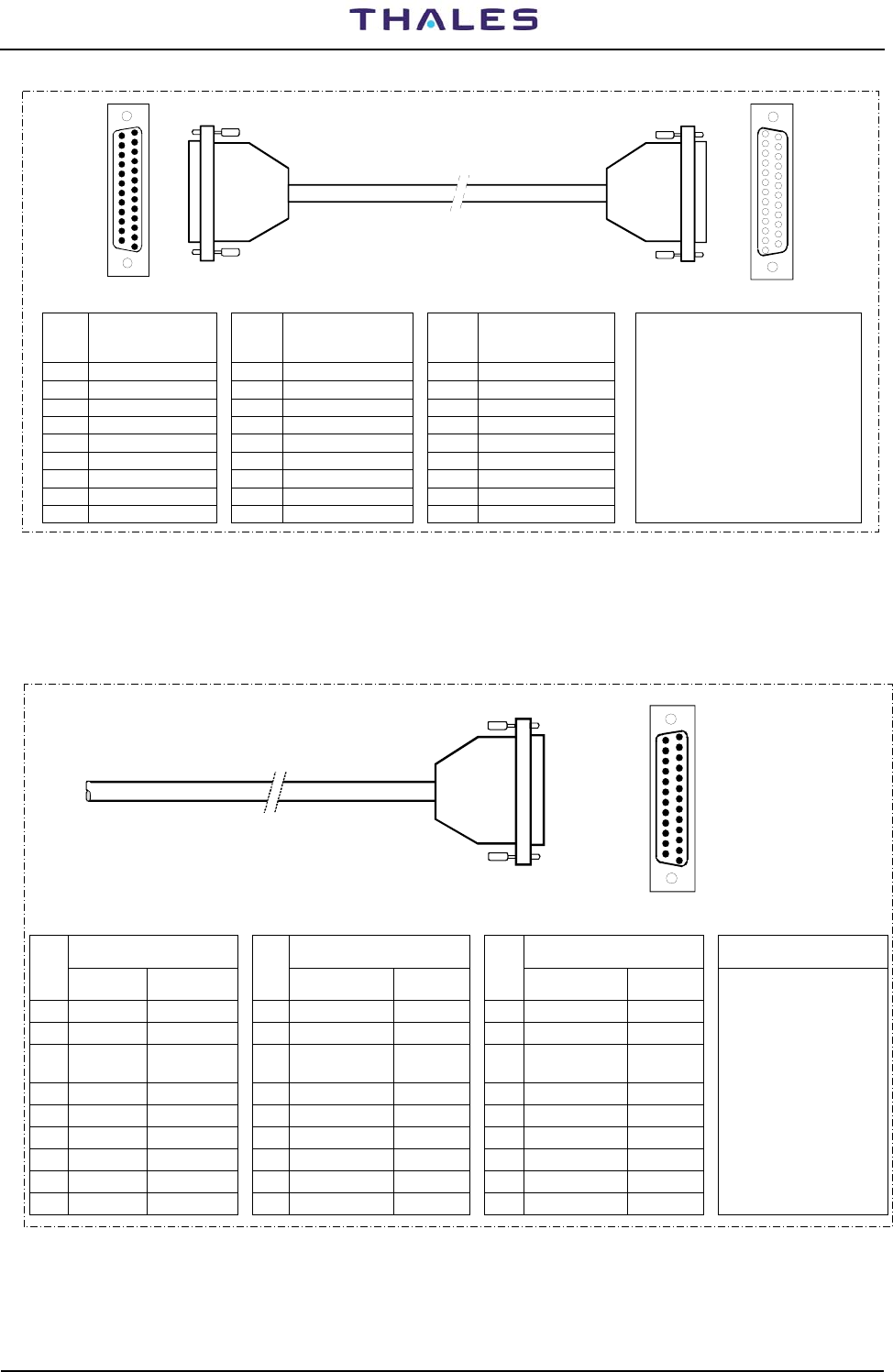
7 LOCAL PC SERIAL CABLE 3 see figure 2.3
8 RS-232 EXTERNAL MODEM CABLE (option) 3 see figure2.4
9 INTERFACE FACILITY CABLE 10 see figure 2.5
10 TELEPHONE CABLE (option) 15 Two pair twisted wire telephone cable (screened )
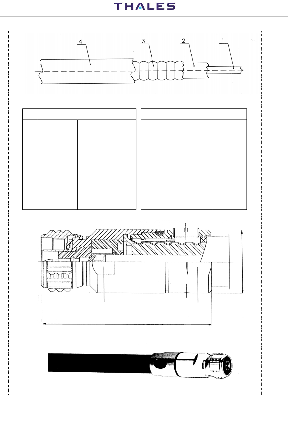
11 LOW LOSS ½” ANTENNA CABLE 25 see figure 2.6.
12 LOW LOSS ½” MONITOR CABLE 25 see figure 2.6.
13 LOW LOSS ½” MONITOR CABLE 25 see figure 2.6.
14 OBSTRUCTION LIGHT CABLE (option) 25 see figure 2.7 Three wire 1,5 mm2 shielded cable
Db 25
( 25 pins
Male)
To I/O panel (SK2)
OUT Parallel port
PL2
1
13
14
25
pin side view
PIN
n° Wire Covering
Color
PIN
n° Wire Covering
Color PIN
n° Wire Covering
Color NOTE
1 White 10 Violet 19 WHITE/brown • Reference item of table 2-1:
2 Brown 11 Orange 20 WHITE/green n°5
3 Green bright 12 Bleu (light) 21 WHITE/yellow
4 Yellow 13 Green (dark) 22 WHITE/gray • Signal assignment:
5 Gray 14 WHITE/bleu 23 YELLOW/black see table 2-4b
6 Pink 15 WHITE/violet 24 YELLOW/red
7 Bleu (dark) 16 WHITE/red 25 YELLOW/bleu
8 Red 17 WHITE/pink • Cable screen on the
9 Black 18 WHITE/black connector cover
Figure 2.1. AUX OUT I/O cable
DME 415/435 -Technical Manual
Vol. 1-Section 2 - Installation 955 900 031 C
Vers. D, September 2005 THALES Italia S.p.A.- A. S. D. 2-5
1
13
14
25
SK3
Db 25
( 25 pins
Female)
AUX IN I/O cable
COD. 041917043T
To I/O panel (PL3)
IN Parallel port pin side view
PIN
n° Wire Covering
Color
PIN
n° Wire Covering
Color PIN
n° Wire Covering
Color NOTE
1 White 10 Violet 19 WHITE/brown
• Reference item of table 2-1:
2 Brown 11 Orange 20 WHITE/green n°6
3 Green bright 12 Bleu (light) 21 WHITE/yellow
4 Yellow 13 Green (dark) 22 WHITE/gray
• Signal assignment:
5 Gray 14 WHITE/bleu 23 YELLOW/black see table 2-4a
6 Pink 15 WHITE/violet 24 YELLOW/red
7 Bleu (dark) 16 WHITE/red 25 YELLOW/bleu
• Cable screen on the
8 Red 17 WHITE/pink connector cover
9 Black 18 WHITE/black
Figure 2.2. AUX IN I/O cable
Db 25
( 25 pins
Male)
1
13
14
25
pin side view
PL1 PC Db 9
( 9 pins Female)
pin side view
To I/O panel (SK1)
PC RS232 port To PC
typical COM1 port
1
5
6
9
PIN
n° PL1 Signal
assignment PIN
n° PL1 Signal
assignment PIN
n° PL1 Signal
assignment PIN
n° PC Signal
assignm. NOTE
1 - 10 - 19 - 1 DCD
• Reference item of table 2-1:
2 RXD 11 - 20 DSR 2 RXD n°7
3 TXD 12 - 21 - 3 TXD
4 CTS 13 - 22 RI 4 DTR
5 RTS 14 - 23 - 5 GND
6 DTR 15 - 24 - 6 DSR
7 GND 16 - 25 - 7 RTS
8 DCD 17 - 8 CTS
9 - 18 - 9 RI
Figure 2.3. PC serial cable
955 900 031 C DME 415/435 -Technical Manual
Vol. 1-Section 2 - Installation
2-6 THALES Italia S.p.A.- A. S. D. Vers. D, September 2005
1
13
14
25
Db 25
( 25 pins
Female)
pin side view
Db 25
( 25 pins
Male)
1
13
14
25
pin side view
MDM SK2
SK1
To MODEM To I/O panel (PL1,2)
RS232 Serial port 3,2
PIN
n° Signal
assignment
PIN
n° Signal
assignment PIN
n° Signal
assignment NOTE
1 - 10 - 19 -
• Reference item of table 2-1:
2 TXD1/2 11 - 20 DTR1/2 n°8
3 RXD1/2 12 - 21 -
4 RTS1/2 13 - 22 RI 1/2
5 CTS1/2 14 - 23 -
6 DSR 1/2 15 TXCK1/2 24 -
7 GND 16 - 25 -
8 DCD1/2 17 RXCK1/2
9 - 18 -
Figure 2.4. RS232 External Modem cable
Db 25
( 25 pins
Male)
To I/O panel (SK4,5)
Assoc. Facility EQPT
AF1,2
PL4
PL5
1
13
14
25
pin side view
Wire Covering Color Wire Covering Color Wire Covering Color NOTE
PIN
n° STD
A
lternative
PIN
n° STD
A
lternative
PIN
n° STD
A
lternative
1 White Black 10 Violet Oran/blck
19
W
HITE/brown Bleu/red • Reference item of
2 Brown White 11 Orange Bleu/blk
20
W
HITE/green Red/gre table 2-1: n°9
3 Green
bright Red 12 Bleu (light) Black/whi 21
W
HITE/yellow Oran/gre
4 Yellow Green 13 Green (dark) Red/white 22
W
HITE/gray Blk/Wh/rd • Signal assignment:
5 Gray Orange 14 WHITE/bleu Green/wh 23
Y
ELLOW/black Wh/blk/rd see table 2-6
6 Pink Bleu 15 WHITE/violet Bleu/whit 24
Y
ELLOW/red Rd/blk/wh
7 Bleu (dark) White/blk 16 WHITE/red Black/red 25
Y
ELLOW/bleu Gr/blk/wh
8 Red Red/black
17 WHITE/pink White/red • Cable screen on the
9 Black Green/blk 18 WHITE/black Oran/blk connector cover
Figure 2.5. Interface Facility cable
DME 415/435 -Technical Manual
Vol. 1-Section 2 - Installation 955 900 031 C
Vers. D, September 2005 THALES Italia S.p.A.- A. S. D. 2-7
Table 2-2 - RF coax cable LCF 1/2" CU2Y type - Technical specification
item Mechanical Electrical data
1 Inner conductor Ø 4,8 mm AL/CU clad Characteristic impedance
Relative propagation velocity
50 ±1Ω
88%
2 Dielectric Ø 11,5 mm Foam PE Capacity 76 pF/m
3 Outer conductor Ø 13,8 mm corrugated
copper tube Peak Power rating
Peak RF Voltage rating
23 kW
1,5 kV
4 Jacket Ø 16,1 mm PE black Attenuation @ 20°C 0,073 dB/m
- Weight Approx. 0,23 kg/m Max operating frequency 3000 MHz
- Minimum
bending radius 70 mm: single bending
125 mm: repeated
bending
DC-resistance inner conductor
DC-resistance outer conductor
Typical delay at 1000MHz
1,59 Ω/km
2,0 Ω/km
0.004 µs/m
58
reference plane
Ø 21,8
SW19 SW19
Connector N-plug for LCF 1/2" – 50 Ω
Coax cable with connector N-plug
Figure 2.6. RF coax cable - LCF 1/2"
955 900 031 C DME 415/435 -Technical Manual
Vol. 1-Section 2 - Installation
2-8 THALES Italia S.p.A.- A. S. D. Vers. D, September 2005
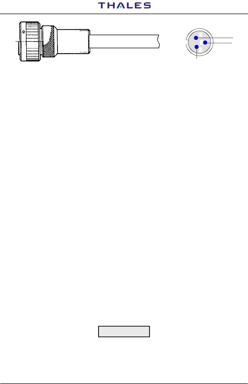
A
C
B
GND
Connector: Cannon - CGL06PG 10SL-3S-C1L
3 wire shielded cable pin solder rear view
Figure 2.7. Obstruction light cable
2.6.2 Grounding
The ground cable must be laid separately and connected permanently to GND terminal of the "Terminal
Board) and to the connecting bolt of the cabinet.
A ground fault external interrupter it is suggested for a rated fault leakage current of 30 mA.
The copper cable, with cross-section 25 mm2, and fitted with a lug for attaching to the ground bolt, is
provided for grounding the beacon. Figures 2.10 and figure 2.12 illustrate how the beacon is grounded.
One end of the cable is inserted in the lug terminal and the other end is connected to the local ground
network, which must comply with the safety regulations stipulated in the specifications.
2.6.3 Power supply connection
The equipment can be powered from either mains, or battery, or both.
The standard version can be powered from a external 48 Vdc. The BCPS rack must be added for VAC
operation and it can either be housed inside the equipment or installed externally as well.
Cabling connections are shown in figures 2.11 and 2.12.
The BCPS unit will have a different structure depending on the type of power supply used. Furthermore,
since the beacon is not provided with any on/off breakers. It will be provided from optional breaker AC and
DC recommended with independent switch for the two power supplies.
When collocated with a System 400 (D)VOR, NDB or ILS Systems a common power supply and battery will
be implemented.
The equipment may be supplied by the mains with a 194 to 260 Vac voltage, 48 to 64 Hz, single phase, or
by an source providing a rated 48 Vdc (external source or 48Vdc battery back-up) direct power supply (40
Vdc to 60 Vdc). Equipment consumption: refer to para. 4.10.1 section 4 on this volume
Connect the mains leads (L= mains phase; N = Neutral; Mains Ground = typical green-yellow color) and
battery leads (+polarity = red cable and negative polarity = black cable) to terminals on "terminal board" as
shown in figure 2.11 or 2.13.
CAUTION
When connecting the DC supply observe the correct polarity ("+ positive" and "- negative")
DME 415/435 -Technical Manual
Vol. 1-Section 2 - Installation 955 900 031 C
Vers. D, September 2005 THALES Italia S.p.A.- A. S. D. 2-9
FAN-96
ANTENNA
Automatic
night switch
Obstruction light
power supply
DME 400
EQUIPMENT
To local ground network
SK1 14
M1 M2
INPUT
Obs. Light
RF
Antenna
connector Antenna
monitors probes
connectors
4
12
13
11
3
2
Power supply Cables 1
5
6
Top of cabinet
Bottom of cabinet
9
Ground bolt
I/O Panel
see fig 2.9
Obstr. Light
10
7
Automatic
mains
breaker
External electrical
switchboard
220Vac
mains
48Vcc
A
utomatic
battery
breaker
BATTERY
Figure 2.8. Installation connections (typical)
955 900 031 C DME 415/435 -Technical Manual
Vol. 1-Section 2 - Installation
2-10 THALES Italia S.p.A.- A. S. D. Vers. D, September 2005
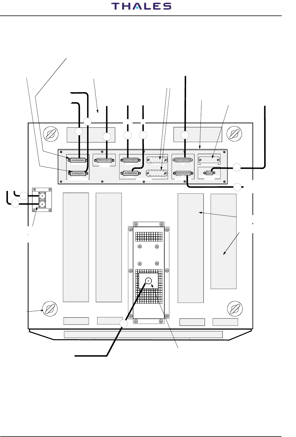
SK6
TACAN ANTENNA
PL7
TEL. LINES
1-6= LINE 1 3-8=LINE 2
ASSOC. FACILITY
AF2
AF1
SK4
SK5
PARALLEL PORT IN (16/31)
PL4
SK3
OUT(16/31)
SK2
PL3
IN (0/15)
OUT(0/15)
PC (RS232)
SK1
PORT 1 (DCE)PORT 3 (DCE/DTE)
PL2
PL1
PORT 2 (DTE)
SERIAL PORT (RS232)
M2
M1
I/O PANEL
12
PC
7
85
OUT
9
10
9
8
N.U.
N.U.
To associated
equipment 2
Identity Facility
6
IN
13
11
N° 4 EYE
BOLTS
Front of cabinet
Rear of cabinet
To antenna
monitors
probes
UNAVAILABLE IF
MDM2 (internal modem)
IS USED
Possible external
MODEM (option)
UNAVAILABLE IF
MDM1 (internal modem)
IS USED
AUX. IN/OUT Parallel
signals ON/OFF To telephon lines
To associated equipment 1
Identity Facility
To DME antenna
To don't obstruct
TOP side area
ANTENNA
CONNECTOR
"N" female type
ANTENNA
MONITORS PROBES
CONNECTORS
"N" type female
AIRING
GRIDS
Figure 2.9. Installation - Cables connections (typical) on top end of equipment
NOTE: Valid for both cabinets type
DME 415/435 -Technical Manual
Vol. 1-Section 2 - Installation 955 900 031 C
Vers. D, September 2005 THALES Italia S.p.A.- A. S. D. 2-11
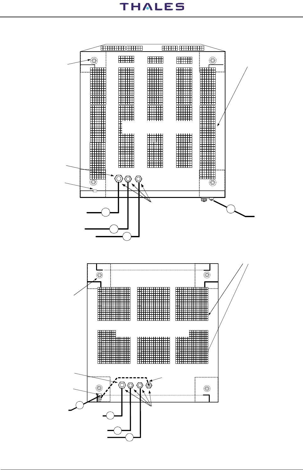
1
4
2
3
Input power supply
cable entry
Ground bolt
Cabinet bottom view
Rear door
Front door
To don't obstruct
BOTTOM side area
N° 4 holes
for fixing
to the plinth
AIRING
GRIDS
- BATTERY CABLE
GROUND CABLE
to local GND network
+ BATTERY CABLE
MAINS CABLE GROUND CABLE
Bush fair-lead
Input power supply
cable entry
Ground bolt
Cabinet bottom view
Rear door
Front door
To don't obstruct
BOTTOM side area
N° 4 holes
for fixing
to the plinth
AIRING
GRIDS
- BATTERY CABLE
GROUND CABLE
to local GND network
1
+ BATTERY CABLE
4
2
MAINS CABLE
GROUND CABLE
Bush fair-lead
3
Figure 2.10. Installation - Cables connections (typical) on bottom of cabinet
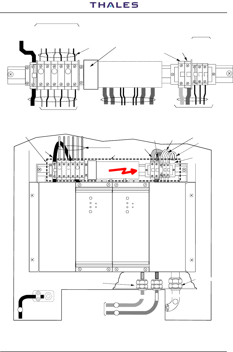
Cabinet 297 509 007
Cabinet 297 509 004
955 900 031 C DME 415/435 -Technical Manual
Vol. 1-Section 2 - Installation
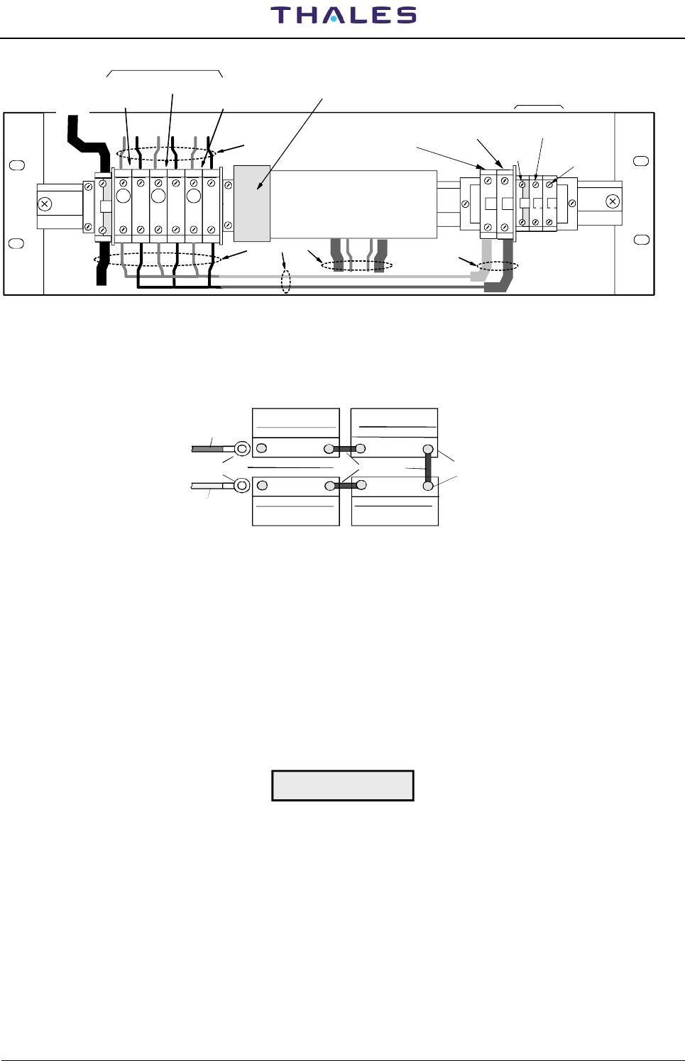
2-12 THALES Italia S.p.A.- A. S. D. Vers. D, September 2005
+ 48 Vdc input
From Battery
+-
Battery return
(negative)
MAINS GND
L - MAINS LINE
N-MAINS NEUTRAL
Factory wired
Factory wired
Factory wired
+++
10A 2A
10A
to TRANSP. 1
to TRANSP.2
to SERVICES
48 Vdc nominal
from BCPS back panel
from MAINS CABLE
to BCPS back panel
GN L
--
-
*to GND
local
network
TERMINAL BAR CONNECTIONS
*) INSTALLATION CONNECTED WIRES
I Batt. & I Nav SHUNTS
(Optional)
Battery Depleted
Breaker
Figure 2.11. Cable connection - Grounding and AC power supply of the Terminal Bar
* BATTERY cables
GND cable
Factory wired
*GND *+48V battery
*Battery return
*Mains cable
* to local
GND network
Bush fair-lead
to BATTERY
*Mains GND
*Mains Phase
*Mains Neutral
RACK BCPS
front view
SAFETY PROTECTION
SAFETY PROTECTION
AC/DC 1
Module OK
Mains OK
V adj
-TP
+
-
AC/DC 2
Module OK
Mains OK
V adj
-TP
+
-
10A
+-LN
Gnd
++-
-
-
+
-
2A
+
10A
3
4
2
1
220 Vac
WARNING
on rear of cabinet
* Mains cable
Bush fair-lead
*) INSTALLATION
CONNECTED WIRES
Figure 2.12. Cables connection - Grounding and AC power supply
NOTE: For cabinet 297 509 004 see fig. 2-10
DME 415/435 -Technical Manual
Vol. 1-Section 2 - Installation 955 900 031 C
Vers. D, September 2005 THALES Italia S.p.A.- A. S. D. 2-13
+ 48 Vdc input
From Battery or
externa power supply
+-
Battery or 48 Vdc
return (negative)
MAINS
GND L - MAINS
LINE
Factory wired
Factory wired
Factory wired
+++
10A 2A
10A
to TRANSP. 1
to TRANSP.2
to SERVICES
40 to 60 Vdc
Not Used
GN L
--
-
to GND
local
network
N-MAINS
NEUTRAL
Battery breaker
I Batt. & I Nav SHUNTS
(Optional)
Figure 2.13. Grounding and external 48 Vdc power supply - Cables connection
2.6.3.1 Batteries
The battery of back up is used in case of blackout, to allow the beacon to keep working without interruption.
+-+-
+-+-
Terminali dei cavi
cavo positivo
cavi di
connessione
Batteria 12V/50A/h
Tensione centrale
cavo negativo
Batteria 12V/50A/h
Batteria 12V/50A/h
Batteria 12V/50A/h
Figure 2.14. Battery connections typical
Battery type and size depend on requirements.
Suggested batteries for back-up power supply must have the following characteristics:
- Output voltage: 48 V nominal (four 12 V unit serially connected: see fig. 2.14);
- Nominal discharge capacity: 50 A/h (this capacity ensures a time duration as at para. 4.10 of section 4);
- Low maintenance types or sealed types;
- Low self-discharge;
- Long life: >4 to 5 years;
- Temperature range: -20 to +50 °C;
- The charge from the equipment, at constant voltage, is typically: 2.25 V/element.
These required characteristics should be completed by technical information from the battery constructor.
CAUTION
The low maintenance battery group must be placed in a low-ventilated
environment, while the other sealed types, may be installed everywhere. In any
case, follow the battery constructor’s instructions.
2.6.3.1.1 Battery duration time (on 230Vac black-out)
The battery 50A/h (at end of 42V voltage), are the following:
DME415=20h - DME435=12h for TX2 stby, TX1 en service, and radiate 800 pps
DME415=18h - DME435=10h for TX2 stby, TX1 en service, and radiate 2700 pps
DME415=17h - DME435=7h pour TX2 stby, TX1 en service and radiate 4800 pps
NOTE: With battery 12 mounts old the back up period duration is typical degraded of 10/15% (see also
the technical information from the battery constructor)
955 900 031 C DME 415/435 -Technical Manual
Vol. 1-Section 2 - Installation
2-14 THALES Italia S.p.A.- A. S. D. Vers. D, September 2005
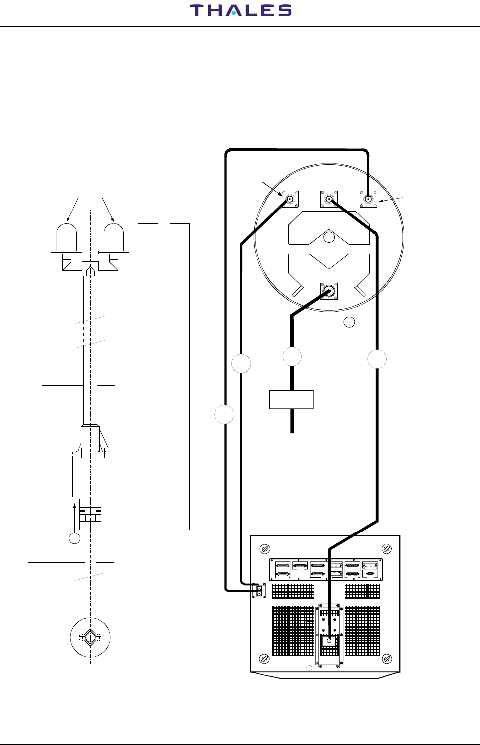
2.6.4 ANTENNA CONNECTION
Mechanical antenna collocation is simple and straightforward with any type of existing VOR, DVOR or ILS
antenna.
Figure 2.15 shows the connections to be performed upon antenna installation and the identification of the
cables supplied.
Characteristics and dimensions: see para. 4.9 on section 4 of this volume (FAN 96 type dimensions are in
figure 2.15)
Obstructions light
OL
M2M1
~3502200
300200
220
60.5 max
90
A
3050
14
13
12
SK6
TACAN ANTENNA
PL7
TEL. LINES
1-6= LINE 1 3-8=LINE 2
ASSO C. FAC ILITY
AF1
AF2
SK4
SK5
PARALLEL PORT IN ( 1 6/ 31 )
PL4
SK3
OUT(16/ 31)
SK2
PL3
IN ( 0 /15)
OUT( 0/15)
PC (RS232)
SK1
POR T 1 ( D CE)POR T 3 ( D CE/ DTE )
PL2
PL1
POR T 2 ( D TE)
SERIA L PORT (RS23 2)
M2
M1
ANTEN NA
CONNECTOR
"N" f emale type
11
11
Connettore
d'ANTENNA
Antenna probe
MONITOR 1
connector
Obstruction light
power supply
View from A
Cabinet top view
Antenna probe
MONITOR 2
connector
Daylight
sensor
Figure 2.15. Cable connections to FAN 96 antenna

DME 415/435 -Technical Manual
Vol. 1-Section 2 - Installation 955 900 031 C
Vers. D, September 2005 THALES Italia S.p.A.- A. S. D. 2-15
2.6.4.1 Antenna coax cables-Attenuations and delays
The interrogating signal from the aircraft received on the beacon antenna, comes the antenna connector
SK1 (equipment input/output RF) with a delay ΔtRF which depends on the antenna coax cable.
This delay, indicated in μs, is given through the following relation:
where: - L: Cable length expressed in m
- P: Relative propagation velocity (for LCF 1/2" cable, typical value: 88%)
- c: Light velocity (300 m/μs)
The low loss "LCF 1/2 inch" standard cable, has a delay of about 0.004 μs/m and an attenuation of about 0.073 dB/m.
The signal received in antenna comes the beacon receiver after a ΔtRF delay, is processed and, after the
reply delay (introduced by the transponder), returns to the antenna from where it is transmitted with an
additional delay ΔtRF (introduced by the antenna coax cable). If it is supposed that the beacon uses a "X"
channel mode (50 μs reply delay), the total delay of the reply signal, generated by the antenna output
system, will be:
Rvel. = ΔtRF + 50 μs + ΔtRF = 2ΔtRF+ 50 μs
The measurement of the reply delay value and its automatic compensation, in 25ns steps compared to the
fixed value, is performed by the monitors through interrogating pulses (Pilot pulse) sent by the transponder
receiver.
The calculated value of the delay and the cables loss according to their length is shown as an example in
the following table 2-3):
Table 2-3 - STD Coax cables
Coax. cable
Parameter Description
Type Length Value
Monitor Cable Loss Loss of monitor coax. cables probes
for monitoring LCF 1/2" 25 m Approx. 2dB
Antenna Cable Loss Loss of antenna coax. cable LCF 1/2" 25 m Approx. 2dB
Delay time Delay of antenna coax. cable LCF 1/2" 25 m Approx. 100 ns
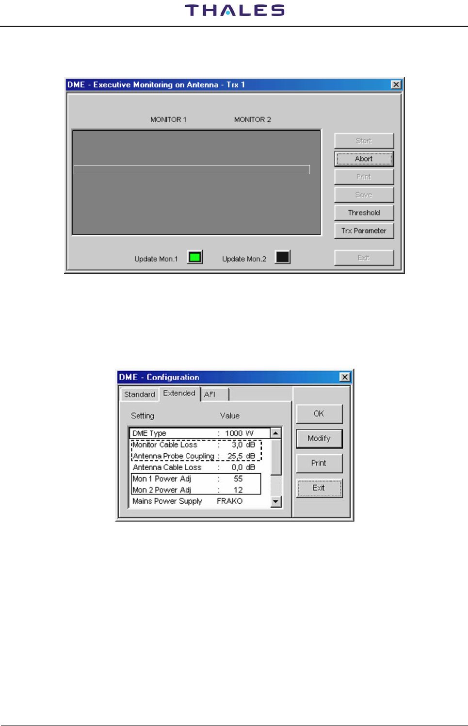
2.6.4.2 Data entry calibration procedure for “EXTENDED CONFIGURATION”
Figure 2.16a) shows an example of typical installation with equipped standard cables.
For calibration and check of the correctness of the power parameters measurement displayed on windows
of the “CHECK”, preset the configuration “EXTENDED CONFIGURATION” (fig. 2.16b) with the procedures
here below (also see in this volume, Appendix “D” PC user EQPT Manager on paragraphs: "Executive
Monitoring on Antenna", "STD measurements & Routine Check on Antenna" and "UTILITY – DME
Configuration").
Remark: The peak power output calibration procedure of the TX100 ad TKW modules is described on
section 5 -MAINTENANCE- para. 5.3.4 and 5.3.5 of this volume. This procedure must be carried
out during the installation, in the event of substitution of module TX100 or/and TKW and also in
case the channel change.
c
P
L
t RF
×
=
Δ

955 900 031 C DME 415/435 -Technical Manual
Vol. 1-Section 2 - Installation
2-16 THALES Italia S.p.A.- A. S. D. Vers. D, September 2005
Obstruction lights
11
12
13
Antenna cable
Monitor 1 probe cable
DME EQPT
Monitoring Antenna
couplers (internal to
antenna)
1
2
Peak Power
meter
Typical values (coax. cable LCF 1/2", 25 m lenght):
Monitoring Antenna couplers :
(for FAN96 antenna)
Monitors cables loss : 2 dB
Antenna cable loss : 2 dB
Transmitted Power
Peak Power Output
PAD
Power meter
protection
attenuator
SK1
Monitor 2
probe cable
10 dB PAD
(only for DME 435)
21dB ± 3dB
Figure 2.16a. Simplified diagram of Antenna coax cables
Figure 2.16b. “EXTENDED CONFIGURATION” – Example of data entry
2.0
21.5
2.0
Mon. 1 Power Adj. : +50
Mon. 2 Power Adj. : -10
Mains Power Supply : Frako

DME 415/435 -Technical Manual
Vol. 1-Section 2 - Installation 955 900 031 C
Vers. D, September 2005 THALES Italia S.p.A.- A. S. D. 2-17
2.6.4.2.1 Check of the OUTPUT POWER measurement on transponder
a) Preset the equipment in "Maintenance" mode (TX in STBY). Unplug the antenna cable and to connect
the "peak power meter", as in fig. 2.16a, to the antenna connector. Switch to “OPERATING” mode, take
notes of the reading of the power peak meter.
b) Restore the connections of the antenna cables. With TX main in OPERATING and on window
“EXTENDED CONFIGURATION – Mon. 1 Power Adj.” Enter, if necessary, a preset value from -100,
99, -98 ......to ..... +98,+99,+100 (Nr. 1 step by step), in order for the measurement reading on
“Executive monitoring: Peak Power Output” to be the same (±2%) as the one indicated on the external
“Peak Power Meter”, previously noted.
c) Repeat point b) for “Mon. 2 Power Adj." on window “EXTENDED CONFIGURATION
2.6.4.2.2 Measurement calibration of the TRANSMITTED POWER (radiated)
a) TX main on antenna in OPERATING. On window “EXTENDED CONFIGURATION – Monitor Cable
loss” enter the value, measured or calculated, of the monitor probe cable loss (for standard cable see
table in previous para. 2.6.4.1)
b) On “EXTENDED CONFIGURATION – Monitor Probe Coupling” enter the value of the coupler at the
operating frequency, a detail that is pointed out on the antenna features. For the model FAN 96 and
FAN 88 the coupling values of the probes are shown on a table enclosed to the package of the antenna
(for antenna FAN 96: typical value 20dB ± 3dB)
c) On “EXTENDED CONFIGURATION – Antenna cable loss” enter the value, measured or calculated, of
the antenna cable loss (for standard cable see table in previous para. 2.6.4.1)
d) The measure indicated in “Transmitted Power”, in theory, should be:
[“Peak Power Output” – Antenna cable loss] in Watt
Some significant power ratios and loss percentage are calculated as per the following table 2-4 :
Table 2-4 - Loss of STD coax cables
Ant. cable loss:
dB Ratio Loss
%
-3 0,5 50
-2 0,63 37
-1,5 0,708 29,2
-1 0,78 22
-0,5 0,89 11
-0,1 0,9772 2,28
Example: with STD cable (25m – LCF ½”) the reading in “Transmitted Power” must be:
1) for DME 415 with 110 W in Peak Power Output: 110 – (110 * 0,347) = 71,83 W
2) for DME 435 with 1050 W in Peak Power Output: 1050 – (1050 * 0,347) = 685.6 W
e) if the reading in “Transmitted Power” is over ± 2% compared to the value mentioned in point d), vary,
step by 0,1dB step , the data on window “EXTENDED CONFIGURATION – Monitor Probe Coupling”
(or in “Monitor cable loss”) up to the limit of ± 2%.
NOTE 1: The sum of the values in dB [Monitor Cable Loss + Antenna Probe Coupling + Antenna
Cable Loss] must be >20 dB and <33 dB, otherwise the data will refused.
NOTE 2: Values in “Transmitted Power” of each monitor can be adjusted within ±10%.
Difference of measure of the values in "Transmitted Power" between the two monitors due to
different attenuations of the coaxial cables, couplers and internal coax cabling, can be
corrected with the trimmer P6 mounted on module MON (shown in fig. 2.17), in order for each
monitor to read measurements that are as equivalent as possible.
955 900 031 C DME 415/435 -Technical Manual
Vol. 1-Section 2 - Installation
2-18 THALES Italia S.p.A.- A. S. D. Vers. D, September 2005
f) The power alarm thresholds of the monitors are programmed for fixed ratios, as data "SETTING" preset
and the monitors also, automatically counts the loss of the coax cables predisposed in "Extended
Configuration".
Examples are shown in table 2-5) for standard cables and with data "SETTING" of monitors power
alarm preset = -3dB:
Table 2-5 - Monitors power alarm threshold examples
Monitors Power Alarm threshold
EQPT Peak power
output Ant. Cable
loss Transmitted
power Peak Power out Transmitt. power
DME AN 415 120 Wp -1,85 dB 78 Wp 60 Wp 39 Wp
DME AN 435 1050 Wp -1,85 dB 686 Wp 525 Wp 343 Wp
Measure of TRANSMITTED POWER - Calibr. adj. trimmer
Figure 2.17. MON module – Trimmer adj. position of the “Transmitted Power” measurement
DME 415/435 -Technical Manual
Vol. 1-Section 2 - Installation 955 900 031 C
Vers. D, September 2005 THALES Italia S.p.A.- A. S. D. 2-19
2.6.5 Adjustment Power Reading by monitor
Reply Delay
Reply Delay
Reply efficiency
Pulse spacing
Peak Power Output
Transmission Rate
Transmitter Freq.
Transmitted Power
50,01
98
12.00
1062
805
1020.0
1001
Watt
ppps
MHz
Watt
%
µs
µs
50,00
96
12.00
805
Watt
ppps
MHz
Watt
%
µs
µs
1065
1000
1020.0
Figure 2.18 Screen of correct measurement by Monitor 1 & 2
To adjust value of Peak Power Output (see figure 2.18) you have to change the following value of preset:
- MON1 Power Adj
- MON2 Power Adj
The range value is from –100 to +100. See figure 2.19.
Figure 2.19 Screen of configuration for power reading adjustment
To adjust value of Transmitted Power for both monitors, you have to change the values of preset. See
figure 2.19
- Monitor Cable Loss
- Antenna Probe Coupling
There is also a possibility to adjust value of power for each monitor, so you can align monitor1 with monitor2
by TRIMMER P6 on monitor board.
NOTE: Be careful !!!! Don’t touch any other TRIMMER on monitor board
Remark: The peak power output calibration procedure of the TX100 ad TKW modules is described on
section 5 -MAINTENANCE- para. 5.3.4 and 5.3.5 of this volume.

955 900 031 C DME 415/435 -Technical Manual
Vol. 1-Section 2 - Installation
2-20 THALES Italia S.p.A.- A. S. D. Vers. D, September 2005
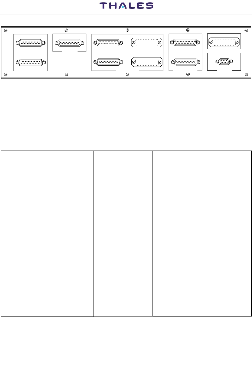
2.6.6 I/O and external interface connections
The following I/O connectors (figure 2.15) are available on the top of the cabinet:
• PL1 - SERIAL PORT 3 (standard DTE) – 25 pin Sub D male connector
• PL2 - SERIAL PORT 2 (DTE) – 25 pin Sub D male connector
• SK1 - PC local operation (reciprocally exclusive to SK1 front panel LCSU) – 25 pin Sub D female
connector
• SK2 - PARALLEL PORT n° 16 out ON/OFF solid state relay lines – 25 pin Sub D female connector
• PL3 - PARALLEL PORT n° 16 in ON/OFF optocoupled lines – 25 pin Sub D male connector
• SK3 - N.U.
• PL4 - N.U.
• SK4 - ASSOCIATED FACILITY (AF1) interface – 25 pin Sub D female connector
• SK5 - ASSOCIATED FACILITY (AF2) interface – 25 pin Sub D female connector
• PL7 - Telephone lines PSTN or dedicated line connection -9 pin Sub D male connector
Figure 2.9 shows all the connections on I/O panel and figure 2.20 shows the connectors of I/O panel on top
end of cabinet.
Tables 2-6a) and 2-6b , (serial ports) and tables 2-7a ,b,c,d (parallel ports), list the pin-out connector
signals. On table 2-8 and table 2-9 are listed the pin-out of the connectors of the telephone line and
Associated.
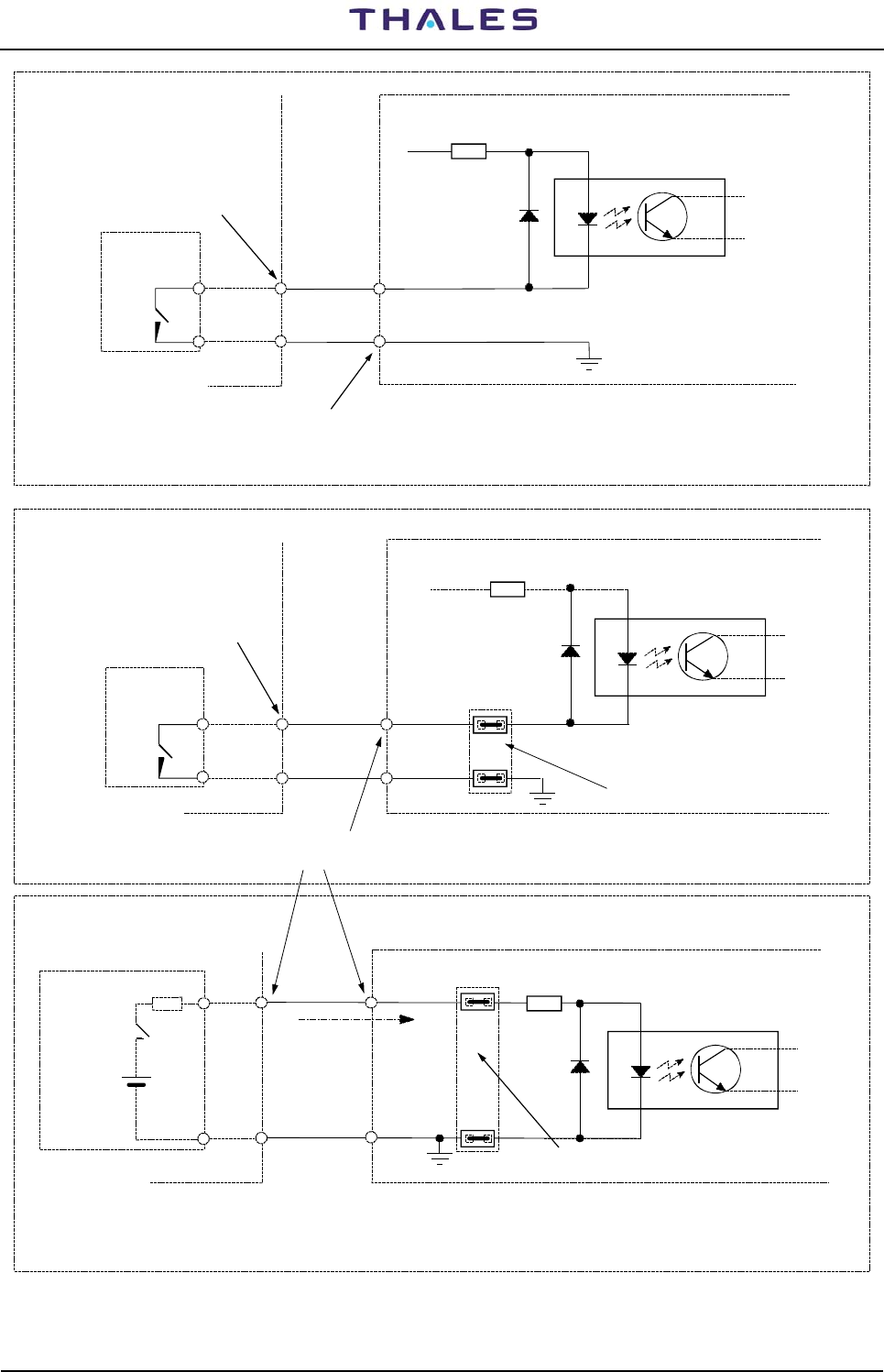
Figure 2.21 shows typical examples of electrical connections related to parallel input lines, user
configurable, for the PL3 connector - PARALLEL IN - of the I/O panel.
The block a) shows the drive connection with the contact to ground of the input signal on Nr. 8 lines. The
blocks b) and c) show the possibility to drive separately, every input line of the allowable ones (eight). Every
line can be driven with a high or low level signal which configurable links (M49, M50, M51, M52) as shown in
figure 2.23 .
On table, 2-7a is shown the parallel input line used by equipment for flag indication of AC/DC power supply
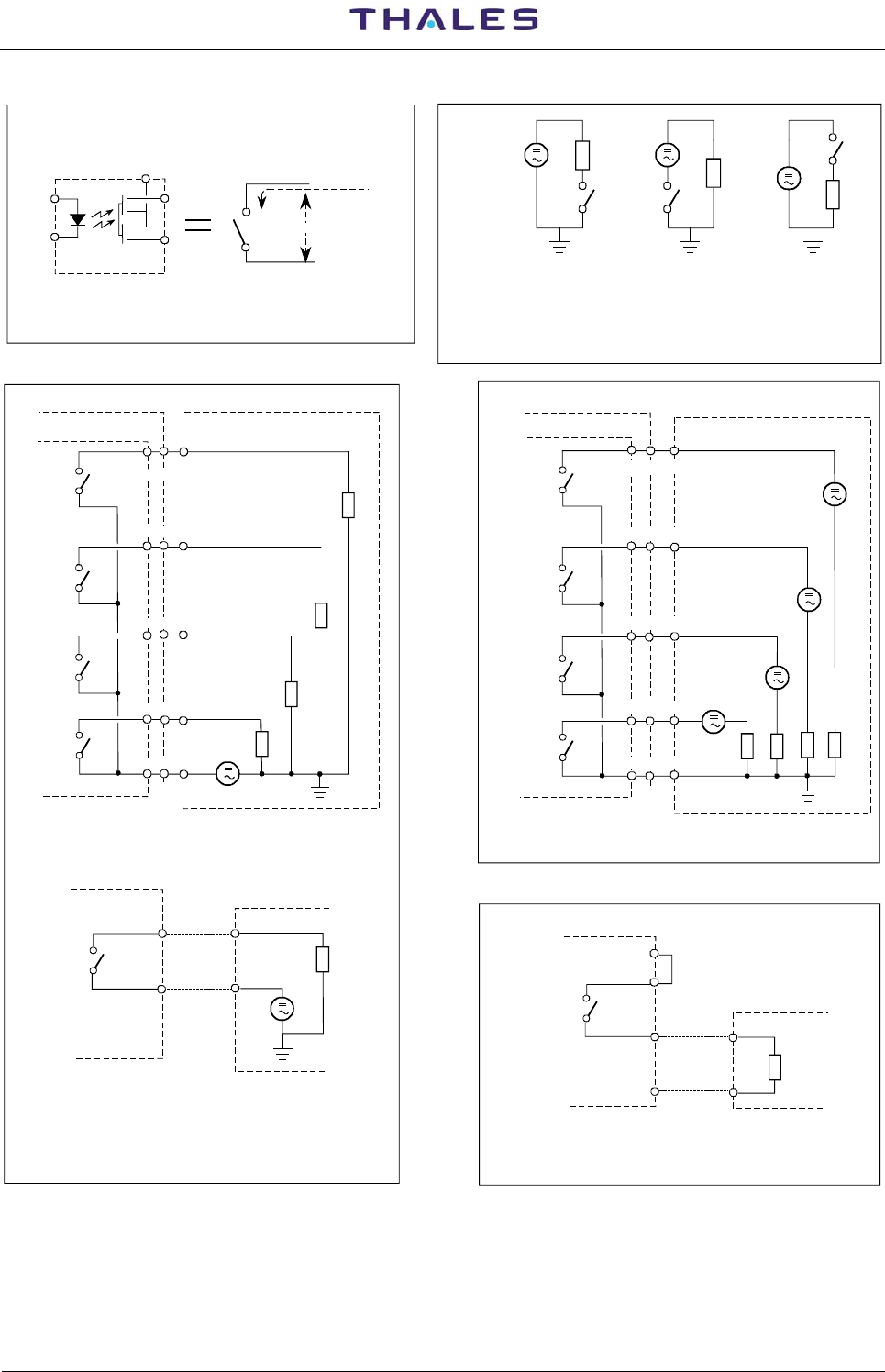
Typical examples of how to use the parallel OUTPUT lines are shown in figure 2.22 where:
− in block b) a single line external connection for a configuration with a distinct common is shown;
− in block c) a four lines connection with only a user power supply (Vg) is shown;
− in block d) a four lines connection with a distinct power supply is shown;
− in block e) a solution with a power supply (5VDC), picked up from the pin 25 of SK2 connector of the
I/O panel is shown.
The commons are arranged in four lines groups, as shown in table 2-7b and in figure 2.22.
DME 415/435 -Technical Manual
Vol. 1-Section 2 - Installation 955 900 031 C
Vers. D, September 2005 THALES Italia S.p.A.- A. S. D. 2-21
SK6
TACAN ANTENNA
PL7
TEL. LINES
1-6= LINE 1 3-8=LINE 2
ASSOC. FACILITY
AF1
AF2
SK4
SK5
PARALLEL PORT IN (16/31)
PL4
SK3
OUT(16/31)
SK2
PL3
IN (0/15)
OUT(0/15)
PC (RS232)
SK1
PORT 1 (DCE)PORT 3 (DCE/DTE)
PL2
PL1
PORT 2 (DTE)
SERIAL PORT (RS232)
PL1 = UNAVAILABLE if MDM 2 IS USED
PL2 = UNAVAILABLE if MDM 1 IS USED
SK1 = PC connection: UNAVAILABLE if PC
connector on FRONT PANEL is USED
SK2 = N° 16 AUXILIARY ON/OFF OUT SIGNALS (standard)
PL3 = N° 16 AUXILIARY ON/OFF IN SIGNALS (standard)
(e.g. possible Site Status Indication)
SK3 = N° 16 AUXILIARY ON/OFF OUT SIGNALS (optional)
PL4 = N° 16 AUXILIARY ON/OFF IN SIGNALS (optional)
SK4 = Associated Facility EQPT 1
SK5 = Associated Facility EQPT 2
SK6 = N.U.
PL7 = N° 2 Telephon Line
Internal MODEM connected
Figure 2.20. I/O panel, top view
Table 2-6a - SK1 on I/O panel and front panel - Serial Ports PC connector pin-out signals
SIGNAL CONNECTOR ON
CSB MODULE SERIAL
DCE
PC CONNECTOR on I/O
PANEL
and on LCSU Front panel NOTE
M22-PIN Nr. Port Nr. PC-SK1- PIN Nr
(Spare) 1 1
(Spare) 2 - 14
RXD 3 1 2
(Spare) 4 - 15
TXD 5 1 3
(Spare) 6 16
CTS∼ 7 1 4
(Spare) 8 17
RTS∼ 9 1 5
(Spare) 10 18
(Spare) 11 6
(Spare) 12 19
GND 13 1 7
DCD∼ 14 1 20
DTR∼ 15 1 8
(Spare) 16 21*) *) pin from 9 to 13 and 22 to 25: N.U.

955 900 031 C DME 415/435 -Technical Manual
Vol. 1-Section 2 - Installation
2-22 THALES Italia S.p.A.- A. S. D. Vers. D, September 2005
Table 2-6b - PL1 and PL2 on I/O panel - Serial Ports MDM connector pin-out signals
SIGNAL CONNECTOR ON
CSB MODULE SERIAL
DTE CONNECTOR on I/O
PANEL NOTE
M22-PIN Nr. Port Nr. MDM1-PL2 -PIN Nr
(Spare) 17 1
(Spare) 18 14
TXD1 19 2 2
TXCK1 20 2 15
RXD1 21 2 3
(Spare) 22 16
RTS∼1 23 2 4
RXCK1 24 2 17
CTS∼1 25 2 5
(Spare) 26 18
DSR1-386 27 6
(Spare) 28 19
PGND 29 2 7
DTR∼1 30 2 20
DCD∼1 31 2 8
(Spare) 32 21*) *) pin from 9 to 13 and 22 to 25: N.U.
M22-PIN Nr
MDM2-PL1- PIN Nr
(Spare) 33 1
(Spare) 34 14
TXD2 35 3 2
TXCK2 36 3 15
RXD2 37 3 3
(Spare) 38 16
RTS∼2 39 3 4
RXCK2 40 3 17
CTS∼2 41 3 5
(Spare) 42 18
DSR2-386 43 6
(Spare) 44 19
PGND 45 3 7
DTR∼2 46 3 20
DCD∼2 47 3 8
(Spare) 48 21*) *) pin from 9 to 13 and 22 to 25: N.U.
Pin 49 to 64 on M22 (CSB) : N.A.

DME 415/435 -Technical Manual
Vol. 1-Section 2 - Installation 955 900 031 C
Vers. D, September 2005 THALES Italia S.p.A.- A. S. D. 2-23
Table 2-7a - PL3 on I/O panel - INPUT Parallel Port Connector pin-out signals
SIGNAL CONNECTOR
ON CSB
MODULE
IN Parallel line
ON/OFF
Pin function
CONNECTOR
on I/O PANEL NOTE
M32-PIN Nr. IN-PL3-PIN Nr
GND 1 PGND 1
VCC 2 +5 VDC 14
OUT3 3 TTL output 2
IAUX0 4 Opto-coupled input
15 b)
IAUX1 5 Opto-coupled input
3 b)
IAUX2 6 Opto-coupled input
16 b)
IAUX3 7 Opto-coupled input
4 b)
IAUX4 8 Opto-coupled input
17 b)
IAUX5 9 Opto-coupled input
5 b)
IAUX6 10 Opto-coupled input
18 b)
IAUX7 11 Opto-coupled input 6 b)
IAUX8 12 Opto-coupled input
19 a) H+5 FTY1 - Indication TRX1 5Vdc faulty
IAUX9 13 Opto-coupled input 7 a) H+5 FTY2 - Indication TRX2 5Vdc faulty
IAUX10 14 Opto-coupled input 20 a) LMNS1 - Mains input found faulty from AC/DC 1
IAUX11 15 Opto-coupled input 8 a) LMNS2 - Mains input found faulty from AC/DC 2
IAUX12 16 Opto-coupled input 21 a) HBDISC – Battery disconnected
IAUX13 17 Opto-coupled input 9 a) LMNS3 - Mains input found faulty from AC/DC 3
IAUX14 18 Opto-coupled input 22 a) HBPDPL – Battery Predepleted
IAUX15 19 Opto-coupled input 10 a) LMNS4 - Mains input found faulty from AC/DC 4
IN0 20 TTL input 23 a) HBCPFTY1 - AC/DC 1 found faulty
IN1 21 TTL input 11 a) HBCPFTY2 - AC/DC 2 found faulty
IN2 22 TTL input 24 a) HBCPFTY3 - AC/DC 3 found faulty
OUT4 23 TTL output 12 a) HBDPOFF – Non active signal
IN3 24 TTL input 25 a) HBCPFTY4 - AC/DC 4 found faulty
PGND 25 GND 13
NOTE
a) Internal use. These signals are used in the equipment for the interconnections of the BCPS unit and
cannot be used for other purposes. Definitions used are contained in the “NOTE” column.
b) Nr.
8 INPUT parallel auxiliary I/O lines, driven by a free contact ON/OFF (closing to ground) (see figure
2.21 block a).

955 900 031 C DME 415/435 -Technical Manual
Vol. 1-Section 2 - Installation
2-24 THALES Italia S.p.A.- A. S. D. Vers. D, September 2005
Table 2-7b - SK2 on I/O panel - OUTPUT Parallel Port Connector pin-out signals
SIGNAL CONNECTOR ON
CSB MODULE OUT Parallel line ON/OFF
Pin function CONNECTOR on
I/O PANEL NOTE
M32-PIN Nr. OUT-SK2-PIN Nr
COM3
26 Relays common for OAUX4,
OAUX5, OAUX6, OAUX7
1
COM4 27 Relays common for OAUX8,
OAUX9, OAUX10, OAUX11 14
OUT2 28 TTL output 2
OAUX0 29 Solid state relay output 15 c)
OAUX1 30 Solid state relay output 3 c)
OAUX2 31 Solid state relay output 16 c)
OAUX3 32 Solid state relay output 4 c)
OAUX4 33 Solid state relay output 17 c)
OAUX5 34 Solid state relay output 5 c)
OAUX6 35 Solid state relay output 18 c)
OAUX7 36 Solid state relay output 6 c)
COM1 37 Relays common for OAUX0,
OAUX1, OAUX2, OAUX3 19
OAUX8 38 Solid state relay output 7 c)
OAUX9 39 Solid state relay output 20 c)
OAUX10 40 Solid state relay output 8 c)
OAUX11 41 Solid state relay output 21 c)
OAUX12 42 Solid state relay output 9 c)
OAUX13 43 Solid state relay output 22 c)
OAUX14 44 Solid state relay output 10 c)
OAUX15 45 Solid state relay output 23 c)
COM2 46 Relays common for OAUX12,
OAUX13, OAUX14, OAUX15 11
OUT0 47 TTL output 24
OUT1 48 TTL output 12
VCC 49 +5 VDC 25
PGND 50 GND 13
NOTE
c) Nr. 16 OUTPUT parallel auxiliary I/O lines (for application examples: see figure 2.22).

DME 415/435 -Technical Manual
Vol. 1-Section 2 - Installation 955 900 031 C
Vers. D, September 2005 THALES Italia S.p.A.- A. S. D. 2-25
Table 2-7c - PL4 on I/O panel (optional) - INPUT Parallel Port connector pin-out signals
SIGNAL CONNECTOR ON
CSB MODULE IN Parallel line
ON/OFF
Pin function
CONNECTOR on
I/O PANEL NOTE
PIN Nr. IN-PL4-PIN Nr
PGND 1 PGND 1
VCC 2 +5 VDC 14
(Spare) 3 2
IAUX16 4 Opto-coupled input 15
IAUX17 5 Opto-coupled input 3
IAUX18 6 Opto-coupled input 16
IAUX19 7 Opto-coupled input 4
IAUX20 8 Opto-coupled input 17
IAUX21 9 Opto-coupled input 5
IAUX22 10 Opto-coupled input 18
IAUX23 11 Opto-coupled input 6
IAUX24 12 Opto-coupled input 19
IAUX25 13 Opto-coupled input 7
IAUX26 14 Opto-coupled input 20
IAUX27 15 Opto-coupled input 8
IAUX28 16 Opto-coupled input 21
IAUX29 17 Opto-coupled input 9
IAUX30 18 Opto-coupled input 22
IAUX31 19 Opto-coupled input 10
(Spare) 20 23
(Spare) 21 11
(Spare) 22 24
(Spare) 23 12
(Spare) 24 25
PGND 25 GND 13

955 900 031 C DME 415/435 -Technical Manual
Vol. 1-Section 2 - Installation
2-26 THALES Italia S.p.A.- A. S. D. Vers. D, September 2005
Table 2-7d - SK3 on I/O panel (optional) - OUTPUT Parallel Port Connector pin-out Signals
SIGNAL CONNECTOR ON
CSB MODULE OUT Parallel line ON/OFF
Pin function CONNECTOR on
I/O PANEL NOTE
PIN Nr. OUT-SK2-PIN Nr
COM7
26 Relays common for OAUX4,
OAUX5, OAUX6, OAUX7
1
COM8 27 Relays common for OAUX8,
OAUX9, OAUX10, OAUX11 14
(Spare) 28 2
OAUX16 29 Solid state relay output 15
OAUX17 30 Solid state relay output 3
OAUX18 31 Solid state relay output 16
OAUX19 32 Solid state relay output 4
OAUX20 33 Solid state relay output 17
OAUX21 34 Solid state relay output 5
OAUX22 35 Solid state relay output 18
OAUX23 36 Solid state relay output 6
COM5 37 Relays common for OAUX0,
OAUX1, OAUX2, OAUX3 19
OAUX24 38 Solid state relay output 7
OAUX25 39 Solid state relay output 20
OAUX26 40 Solid state relay output 8
OAUX27 41 Solid state relay output 21
OAUX28 42 Solid state relay output 9
OAUX29 43 Solid state relay output 22
OAUX30 44 Solid state relay output 10
OAUX31 45 Solid state relay output 23
COM6 46 Relays common for OAUX12,
OAUX13, OAUX14, OAUX15 11
(Spare) 47 24
(Spare) 48 12
VCC 49 +5 VDC 25
PGND 50 GND 13

DME 415/435 -Technical Manual
Vol. 1-Section 2 - Installation 955 900 031 C
Vers. D, September 2005 THALES Italia S.p.A.- A. S. D. 2-27
Table 2-8 - PL7 on I/O Panel - Telephone line Connector pin-out signals
PIN Signal Line
1 Tla1 1
6 TLb1 1
3 Tla2 2
8 TLb2 2
PIN 2,4,5,9 spares
Table 2-9 - SK4 and SK5 on I/O Panel - AFI Connectors pin-out signals
Connector SK4 (AF1) Connector SK5 (AF2) NOTE
PIN Signal PIN Signal
1 DIDFAFL1 1 DIDFAFL2
Identification from Assoc. Facility (Low)
2 DAF STL1 2 DAF STL2 Associated Facility Status (Low)
3 DRD AVL1 3 DRD AVL2 Redundancy availability (Low)
4 DBC OKL1 4 DBC OKL2 Beacon OK (Low)
5 DBC IAML1 5 DBC IAML2 N.U.
6 DI DTAFL1 6 DIDTAFL2
Identification to Assoc. Facility (Low)
7 DAF SELL 7 DAF SELL Associated Facility Selection (Low)
8 (Spare) 8 (Spare)
9 (Spare) 9 (Spare)
10 (Spare) 10 (Spare)
11 (Spare) 11 (Spare)
12 (Spare) 12 (Spare)
13 PGND 13 PGND
14 DI DFAFH1 14 DI DFAFH2 Identification from Assoc. Facility (High)
15 DAF STH1 15 DAF STH2 Associated Facility Status (High)
16 DRD AVH1 16 DRD AVH2 Redundancy availability (High)
17 DBC OKH1 17 DBC OKH2 Beacon OK (High)
18 DBC IAMH1 18 DBC IAMH2 N.U.
19 DI DTAFH1 19 DI DTAFH2 Identification to Assoc. Facility (High)
20 DAF SELH 20 DAF SELH Associated Facility Selection (High)
21 (Spare) 21 (Spare)
22 (Spare) 22 (Spare)
23 (Spare) 23 (Spare)
24 (Spare) 24 (Spare)
25 PGND 25 PGND Ground
955 900 031 C DME 415/435 -Technical Manual
Vol. 1-Section 2 - Installation
2-28 THALES Italia S.p.A.- A. S. D. Vers. D, September 2005
2.2 kohm
+5V
IAUX0...7
M32 - CSB
PL3 - I/O Panel
GND
INPUT Optocoupler device
User
Free Contact
IAUX8...15
M32 - CSB
PL3 - I/O Panel
GND
INPUT Optocoupler device
M49,50,51,52
Link Bridge
b) - IOAX8...15- Input Ground Signal (active low)
a) - IOAX0...7- Input Ground Signal (active low)
2.2 kohm
IAUX8...15
M32 - CSB
PL3 - I/O Panel
GND
INPUT Optocoupler device
User Contact
M49,50,51,52
Link Bridge
+
User
Voltage
Generator
(5V)
R
Vg
Add R for Vg > 5V
2.2 kohm
+5V
c) - IOAX8...15 - Input Positive Voltage Signal
Pins on connectors:
see table 2-2
Pins on connectors:
see table 2-2
Pin on connectors:
see table 2-2
Pins on connectors:
see table 2-2
Link Set:
see figure 2-4
Link Set:
see figure 2-4
GND
GND
2....8 mA max
User
Free Contact
Figure 2.21. Parallel Input Lines application
DME 415/435 -Technical Manual
Vol. 1-Section 2 - Installation 955 900 031 C
Vers. D, September 2005 THALES Italia S.p.A.- A. S. D. 2-29
IC optoelectronic
switch device
a) Equivalent schematic symbol
I max = 50 mA
V max = 100 V
Generator
COMMON
GND option
DC or AC
Ld
COMMON COMMON
Common
Vg & Switch Common
Load & Switch Common
Vg. & Load
b) Single line - Application Examples
N.U.
M32 - CSB
SK4 - I/O Panel
M32 - CSB
SK4 - I/O Panel
Ld
c) User Load and power supply
with same return
d) User load supplied
from different generators
NOTE:
See also pin-function table 2-2. User External Load = Ld
Vg = DC or AC user Generator (or user power supply)
Vg
Vg
Vg
Vg
Vg
Ld
Ld
Ld
Ld Ld Ld Ld
Ld
Ld
Vg Vg
Vg
Ron max = 50 ohm
Ld
Common
OAUX User Circuit
25 SK4
+5V
GND
13 SK4
Ld
Common
OAUX User Circuit SK4 - I/O Panel
Vg
User circuit
e) User load supplied
from +5VDC DME equipment
Common 1,3,4,2
OAUX 0,4,8,12
OAUX 1,5,9,13
OAUX 2,6,10,14
OAUX 3,7,11,15
User circuit
OAUX 0,4,8,12
OAUX 3,7,11,15
Common 1,3,4,2
OAUX 2,6,10,14
OAUX 1,5,9,13
SK4 - I/O Panel
Figure 2.22. Parallel Output Lines application
955 900 031 C DME 415/435 -Technical Manual
Vol. 1-Section 2 - Installation
2-30 THALES Italia S.p.A.- A. S. D. Vers. D, September 2005
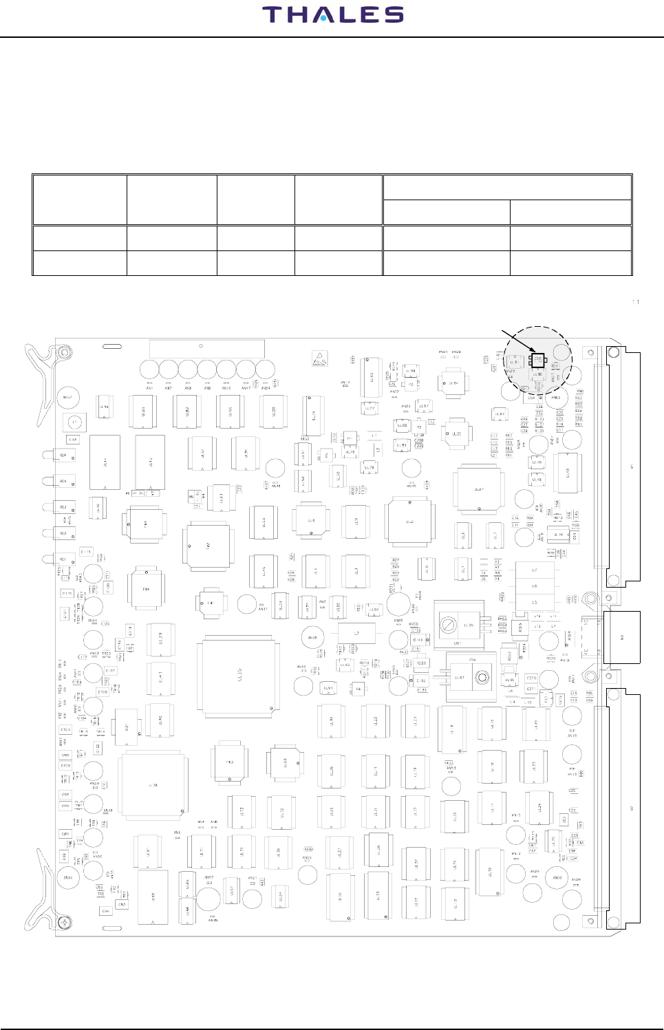
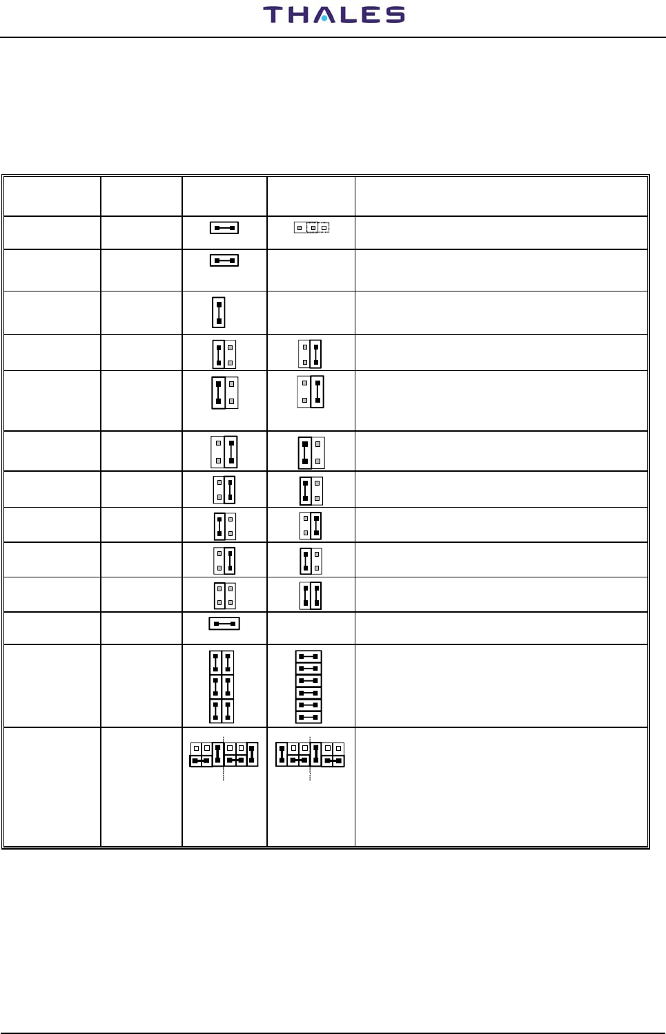
2.6.7 Link set - Jumper presetting
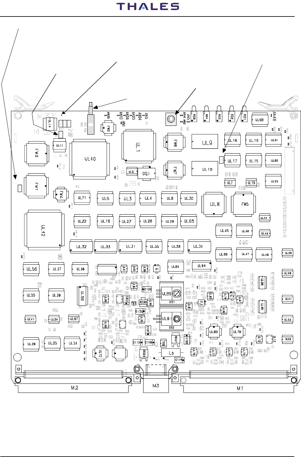
The right positioning of linker on CSB module is shown in figure 2.23 with layout of PBA on fig. 2.24
The right positioning of linker on DMD module is shown in figure 2.25 with layout of PBA
The right positioning of linker on MON module is shown in figure 2.26 with layout of PBA
The right positioning of linker on TX module is shown in figure 2.27 with layout of PBA
The right positioning of linker on AFI module is shown in figure 2.28 with layout of PBA
Schematic
Reference Function Link Factory
preset Alternative
link position NOTE
M1 Battery BT1
1 2 1 2
The link is open for storage or transportation purpose.
Must be closed during normal operation
M3 NMI from
WATCH DOG
(WD) 1 2
The link used OFF, only for laboratory test
M6 WDL Auto-
reset repeater
of WD
1
2
Allows multiple reset in case the CPU does not toggle the
watch dog input
M9 VCC/VBAC
3
4
1
2
3
4
1
2
Jumper on 3-4 = Memory supplied from VCC
Jumper on 1-2 = Memory supplied from VBAC
M10 MCS2
CHIP
SELECT
3
4
1
2
3
4
1
2
Jumper on 3-4 = CHIP SEL for Memory supplied from
battery BT1
Jumper on 1-2 = CHIP SELECT for Memory supplied
from VCC
M11 EPROM
Memory
3
4
1
2
3
4
1
2
Jumper on 1-2 = 4 MBit Memory
Jumper on 3-4 = 1 MBit Memory
M12 SRAM
Memory
3
4
1
2
3
4
1
2
Jumper on 1-2 = 1 MBit Memory
Jumper on 3-4 = 4 MBit Memory
M19
INT3 3
4
1
2
3
4
1
2
N.U. - Jumper on 1-2 =IAUX8 Selection
N.U. - Jumper on 3-4 = INTEXP Selection
M24 Serial Data
RX
3
4
1
2
3
4
1
2
Jumper on 1-2 = Channel 4 used as RS232
Jumper on 3-4 = Channel 4 used as RS485
M25 TX-RX 3
4
1
2
3
4
1
2
No Jumper =Allows a four wire serial RS-485
Jumper on 3-4 & 1-2 = Allows a two wire serial RS-485
M28 ENTXCK
21
Disable RS-485 CLOCK transmission
M31 DTE/DCE
Channel 3
Serial line
switch
7
8
9
10
11
12
6
5
4
3
2
1
6
5
4
3
2
1
7
8
9
10
11
12
Jumper on 1-12, 2-11, 3-10, 4-9, 5-8, 6-7 = DCE
configuration
Jumper on 1-2, 12-11, 3-4, 10-9, 5-6, 8-7 = DTE
configuration
M49
(IAUX8 & IAUX9)
M50 (IAUX810
& IAUX11)
M51 (IAUX12 &
IAUX13)
M52 (IAUX14 &
IAUX15)
Parallel ports
Input signals
switch for
photocoupler
123456
121110987
123456
121110987
Jumper on 4-9, 7-8 =Ground input signal for IAUX8,
IAUX10, IAUX12, IAUX14
Jumper on 1-12, 11-10 =Ground input signal for IAUX9,
IAUX11, IAUX13, IAUX15
Jumper on 4-9, 7-8 = Positive voltage input signal for
IAUX8, IAUX10, IAUX12, IAUX14
Jumper on 1-12, 11-10 = Positive voltage input signal for
IAUX9, IAUX11, IAUX13, IAUX15
Figure 2.23 . List of Links Set on CSB Module
Jumper: default position
M9, M11, M12, M24: link 1-2 M10, M19: link 3-4 M49, M50, M51, M52: link 7-8, 4-9, 10-11, 1-12
M3, M6, M28: link ON M25: open M31: link 1-2, 3-4, 5-6, 7- 8, 9-10, 11-12
M1= Normal operation: link ON. Open during transport and storage only

DME 415/435 -Technical Manual
Vol. 1-Section 2 - Installation 955 900 031 C
Vers. D, September 2005 THALES Italia S.p.A.- A. S. D. 2-31
M18
M30
M22
1
67
12
M21
Push button
RD4
Watch dog
red LED
1
12
6
7
M52
M51
M50
M49
M53
M6
M28
M1
1
2
3
4
1
2
3
4
1
2
3
4
1
2
3
4
M10
M24
M19
RX Indication
green LED
TX Indication
112
2
M31
I1
Reset
1
2
3
4
1
2
3
41
2
3
4
M3
M12
M9 M11
12
12
I2
M25
M32
Dip Switch (N.U.)
green LED
Figure 2.24. Links Setting on CSB Module
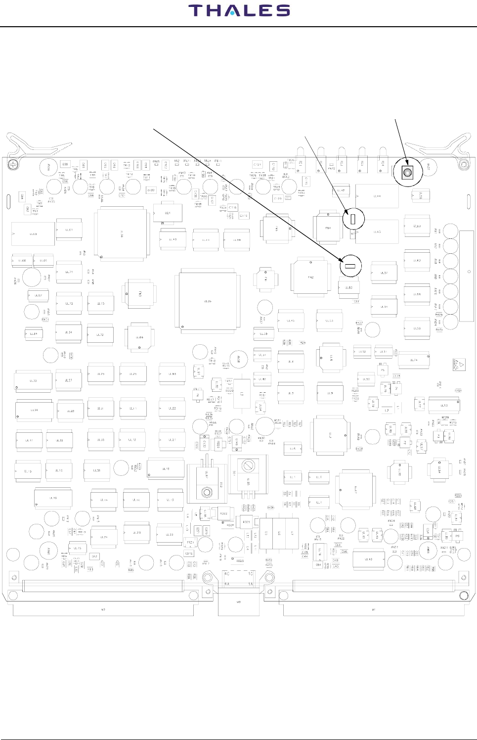
The jumpers topographic position on PBA DMD module is shown in figure 2.25
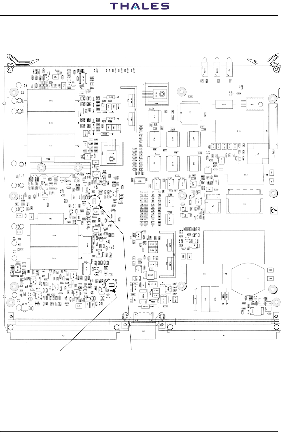
The jumpers topographic position on PBA MON module is shown in figure 2.26
The jumpers topographic position on PBA TX100 module is shown in figure 2.27
The jumpers topographic position on PBA AFI module is shown in figure 2.28
955 900 031 C DME 415/435 -Technical Manual
Vol. 1-Section 2 - Installation
2-32 THALES Italia S.p.A.- A. S. D. Vers. D, September 2005
I1
CM1-Pushbutton that forces
the TRX on Antenna
I1-CPU Reset Pushbutton
M9-Normal OPEN
(N.U.)
enabled: jumper CLOSED (NORMAL)
disable: jumper open
M6 - Watch-dog M7,M12,M13 - NORMAL OPEN
ON=Possible serial line
CM1
I1
1
2
M9
M7
1
M12M13
2
1
2
1
2
M6
1
2
M8 - NORMAL OPEN
ON=Monitor command:
forces TX in STBY
1
2
M8
Figure 2.25. Links Setting on DMD Module
DME 415/435 -Technical Manual
Vol. 1-Section 2 - Installation 955 900 031 C
Vers. D, September 2005 THALES Italia S.p.A.- A. S. D. 2-33
I1
1
2
M8
1
2M6
enabled: jumper CLOSE (NORMAL)
disable: jumper open
M8 - Watch-dog I1 - CPU Reset
Pushbutton
M6 - OFF=NORMAL
ON=Change of RAM
Memory Size
Figure 2.26. Links Setting on MON Module
955 900 031 C DME 415/435 -Technical Manual
Vol. 1-Section 2 - Installation
2-34 THALES Italia S.p.A.- A. S. D. Vers. D, September 2005
M6
1
2
M8 Jumper: ON=TX 100 W
OFF= TKW 1kW
M6 Jumper: OFF=TX 100 W
ON= TKW 1kW
M8
1
2
Figure 2.27. Links Setting on TX Module

DME 415/435 -Technical Manual
Vol. 1-Section 2 - Installation 955 900 031 C
Vers. D, September 2005 THALES Italia S.p.A.- A. S. D. 2-35
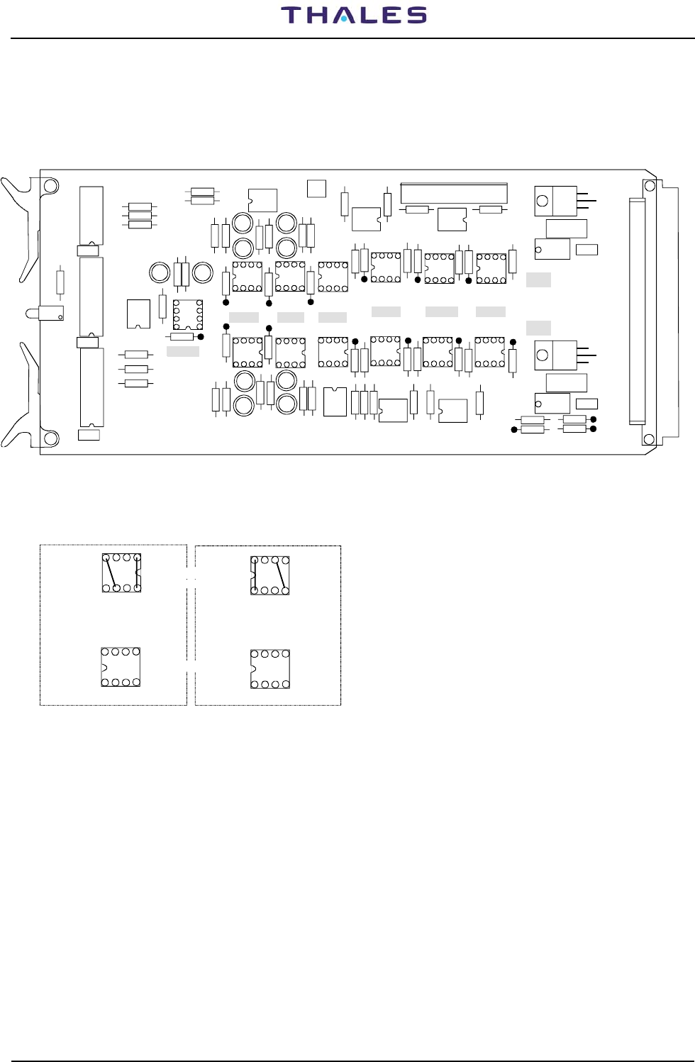
2.6.8 Associated Facility Interface
Electrical interfacing, i.e. identity association can be easily performed as well, by means of a highly flexible
interface board (AFI), inside the DME cabinet.
The DME ground beacon can be associated to VHF equipment such as a VOR or ILS. In this case, the
beacon must be equipped with the appropriate AFI interface module.
The DME can operate either as master or as slave in the association (software configurable), according to
the VOR or ILS capability and to system requirements.
A cable with a single connector fitted is supplied for this connection. This connector must be connected to
connector SK4 or SK5 (called AF1 or AF 2 ASSOCIATED FACILITY) on the I/O panel of the equipment (on
top of the cabinet). The other end of the cable must be connected to the associated VHF equipment.
AF1 or AF2 are selected by means of an external switch (e.g. by Control tower room): see applications in
figure 2.29. In default condition, is enabling the AF1 connector.
The connection to associated equipment of the identity and beacon status signals input and output, is
shown in the figure 2.29 (application) and the block diagram is shown in figure 1.30 (section 1 - General
information).
The lists of the pin signals on connectors SK4 and SK5, on top end I/O panel, are in Tables 2-9 and 2-10.
It is possible change the current source (source external or source internal) rotating 180 degree the 8 pin
DIL header plug, shown in figure 2.28, of the module AFI layout for a correct positioning of the links
Figure 2.30 gives a few association examples with equipment associated.
Table 2-10 - AFI Connectors pin-out signals
SK4 pin SK5 pin AFI PBA - M1 pin
Acronyms Definition H L H L H L
AF SEL Input-Associated Facility selection 20 7 20 7 18c 18a
ID FAF 1 Input- Identification from Associated Facility 14 1 - - 3a 4a
AF ST 1 Input- Associated Facility Status 15 2 - - 5a 6a
ID FAF 2 Input- Identification from Associated Facility - - 14 1 3c 4c
AF ST 2 Input- Associated Facility Status - - 15 2 5c 6c
ID FTF 1 Output - Identification to Associated Facility 19 6 - - 16a 17a
BC OK 1 Output- Beacon OK 17 4 - - 12a 13a
RD AV 1 (*) Output- Redundancy Available 16 3 - - 7a 8a
BC IAM 1(*) Output- Beacon IA Mode degraded 18 5 - - 14a 15a
ID TAF 2 Output - Identification to Associated Facility - - 19 6 16c 17c
BC OK 2 Output- Beacon OK - - 17 4 12c 13c
RD AV 2 (*) Output- Redundancy Available - - 16 3 7c 8c
BC IAM 2 (*) Output- Beacon IA Mode degraded - - 18 5 14c 15c
ID FAF To transponder - Identification - 22a
AF ST To transponder - Status - 22c
ID TAF From transponder - Identification - 25a
BC OK From transponder – Beacon OK - 24a
NOTE 1: (*) N.U. on DME/N
NOTE 2: SK4 used for Associated equipment AF1 (standard default).
SK5 used for Associated equipment 2. It is used also on possible emergency conditions (e.g. failure
on AF1 section), if equipment 2 is not available (in this case, the pin 7 and 20 of "AF SEL" signal will
be short-circuited).
955 900 031 C DME 415/435 -Technical Manual
Vol. 1-Section 2 - Installation
2-36 THALES Italia S.p.A.- A. S. D. Vers. D, September 2005
14
5
8
Internal current source
(default) External current source
Header plug rotate of 180°
INPUT Signals (H&L):
ID FAF=Identity from Associated Facility equipment
AF ST= Associated Facility equipment Status
AF SEL= Associated Facility equipment Selection
OUTPUT Signals (H&L):
ID TAF=Identity to Associated Facility equipment
BC OK= Beacon OK
RD AV=Redundance Availability (N.U.)
BC IAM=Beacon degraded IAM (N.U.)
14
5
8
AF SEL
ID FAF AF ST RD AV BC OK BC IAM ID TAF
TR5 TR10 AF1
AF2
R43
UL3
UL2
UL1
R18
R13
R23
R24 R25
R1
RD3
R2 R3 R4
R17 R22
R21
R11
R12
R16
RD11 RD4 RD5
RD9
RD10
RD1
RD2
RD12 RD13
R20
R10 R15 R9 R14 R19
R32
R8
R6 R5
RD8
R33 R31 R30 R29 R28
RD7
OP7
R7
M1
RD14
RD16
RD15
R40
R26 R27
M8
R38
R37
R36
C7
C6
C5
RD6
OP4
R42
R41
R34
R39
R35
M2
TR3
TR8
OP1
TR4
TR9
M3 M4
OP2 OP3
M5 M6 M2M7
RD17
L1
C3 C1
RD18
L2
C4 C2
M9
OP5OP6
M10
M11
M12M13
M14
TR1
TR6
TR2
TR7 OP7
RD19
(8 pin DIL)
HEADER PLUG
PBA SOCKET
Figure 2.28. Header plugs setting on AFI Module
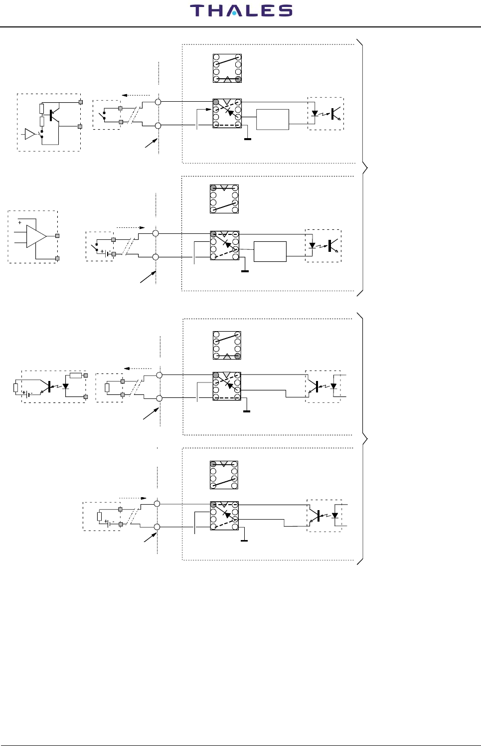
DME 415/435 -Technical Manual
Vol. 1-Section 2 - Installation 955 900 031 C
Vers. D, September 2005 THALES Italia S.p.A.- A. S. D. 2-37
1
4 5
8
AFI PBA
5mA
Limiter
Optocoupler
INTERNAL current source
(default)
1
4 5
8
USER Switch examples
5mA
Limiter
Optocoupler
EXTERNAL current source
13V/5mA max
SK4/AF1
SK5/AF2 AFI PBA
Cabinet
Top End
ID FAF=Identity from
Associated equip.
AF ST= Associated
equipment Status
AF SEL= Associated
equipment Selection
L
H
L
H
1
4 5
8
AFI PBA
USER Load examples Optocoupler
INTERNAL current source
(default)
1
4 5
8Optocoupler
EXTERNAL current source
Cabinet
Top End
13V/10mA max
SK4/AF1
SK5/AF2 AFI PBA
ID TAF=Identity to
Associated equipment
BC OK= Beacon OK
RD AV=Redundance
Availability
(N.U.on DME/N)
BC IAM=Beacon degraded
in IAM
(N.U. on DME/N)
L
H
L
H
USER
Load
L
H
RL
RL
RL
L
H
L
H
USER Switch examples
40V max/5V min/10mAmax
HEADER
position
SOCKET
SOCKET
HEADER
position
HEADER
position
SOCKET
HEADER
position
SOCKET
NOTE: Pin-out on SK4/SK5 according to tables 2-6 & 2-7 and to AFI module layout fig. 2.23
AF1 = Associated Facility equipment 1 (default)
AF2 = Possible Associated Facility equipment 2
INPUT signal "AF SEL": with user switch OFF (open)
the only AF1 (EQPMT 1) is enabled;
with user switch ON, the only AF2
(EQPMT 2) is enabled
Cabinet
Top End
Cabinet
Top End
+15V
+15V
+15V
+15V
SK4/AF1
SK5/AF2
40V max/5V min/5mA
SK4/AF1
SK5/AF2
INPUT Signals (H&L):
OUTPUT Signals (H&L):
Figure 2.29. AFI Module - Input and output signals application
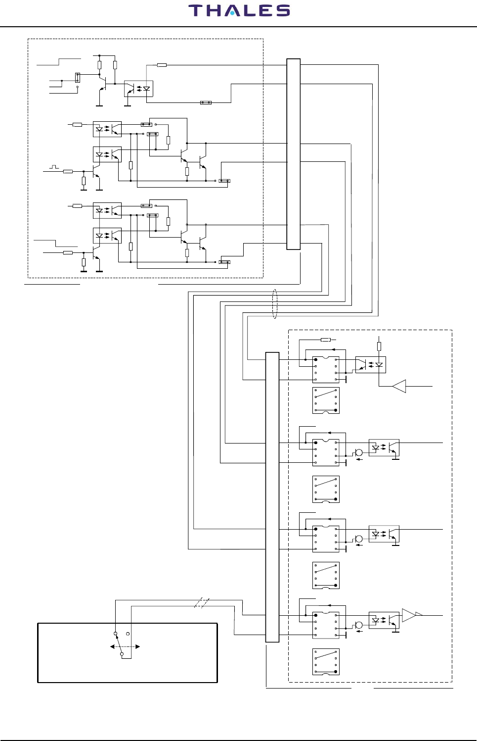
955 900 031 C DME 415/435 -Technical Manual
Vol. 1-Section 2 - Installation
2-38 THALES Italia S.p.A.- A. S. D. Vers. D, September 2005
V9 7
+
ID CODE DME
2
37 PIN
CSL module P/N 83134_23101
1
X15
V98
1
2
3
X2 5
DME_STATUS
DMSD1
DMSD2
V75
V77
123
1X11
X7
1
1
23
1
V96
V78 V7 6
X5
X12
17
VOR KO
VOR
OP
X8
X6
DME FTY DME OK
AFI - CSL module 83134_23101
ASSOCIATION
1
23
2
3
23
23
DBC_OKH
+
+
36
Associated Equipment
Association specification
- DME: "slave code/synch"
- DME: Receive from AF the signals:
a) I DFAF (Identity from Associated Facility)
b) AF-ST (Associated Facility Statu)
- DME Send to AF the signal:
a) BC-OK (Beacon OK)
ATC TOWER
control room
SK5 ENABLED (AF 2)
SK4 DISABLED (AF 1)
SK4 ENABLED (AF 1)
SK5 DISABLED (AF 2)
AF SELECTOR Switch
Connector
DBC_OKL
18
34 DI DFAFH
DI DFAFL
16
35 DAF_STH
DAF_STL
+AFI
1
+15V
1
1
M2/14
M5/11
M3 / 1 3
SK4
(AF1)
SK5
(AF2)
+15 V
+15V
+15V
M8
1K
5mA
5mA
5mA
DME
HEADER set for:
"INTERNAL current source"
SOCKET
HEADER
HEADER
SOCKET
HEADER
SOCKET
HEADER
SOCKET
17
4
14
1
15
2
20
7
DBC_OK
DI DFAF
DAF_ST
1
1
1
1
1
LAF1SEL
Figure 2.29a. AFI Module – Association example with VOR/ILS 400
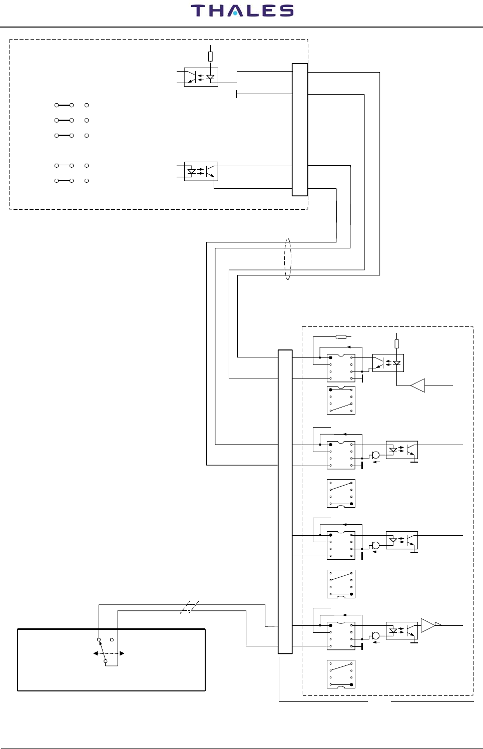
DME 415/435 -Technical Manual
Vol. 1-Section 2 - Installation 955 900 031 C
Vers. D, September 2005 THALES Italia S.p.A.- A. S. D. 2-39
DBC_OKH
DBC_OKL
DIDFAFH
DIDFAFL
AFI
- CI 121 0A NORMARC
ASSOCIATION
NORMARC
CI 1210A
+
P8
1
2
5
6
S1
S2
S3
S7
S8
3
21
DAF_STH
DAF_STL
OUT_DMEP
OUT_DMEN
ACT_DMEP
ACT_DMEN
Connection Interface PBA
Association specification
- DME: "slave code/synch"
- DME: Receive from AF the signals:
a) I DFAF (Identity from Associated Facility)
b) AF-ST (Associated Facility Statu)
- DME Send to AF the signal:
a) BC-OK (Beacon OK)
ATC TOWER
control room
SK5 ENABLED (AF 2)
SK4 DISABLED (AF 1)
SK4 ENABLED (AF 1)
SK5 DISABLED (AF 2)
AF SELECTOR Switch
+AFI
1
+15V
1
1
M2/14
M5/11
M3 / 1 3
SK4
(AF1)
SK5
(AF2)
+15 V
+15V
+15V
M8 LAF1SEL
1K
5mA
5mA
5mA
DME
HEADER set for:
"INTERNAL current source"
SOCKET
HEADER
HEADER
SOCKET
HEADER
SOCKET
HEADER
SOCKET
17
4
14
1
15
2
20
7
DBC_OK
DI DFAF
DAF_ST
1
1
1
1
1
(2)
(1)
(1)
(1) (1)
"EXTERNAL current source"
(2)
Figure 2.29b. AFI Module – Association example with VOR/ILS NORMAC
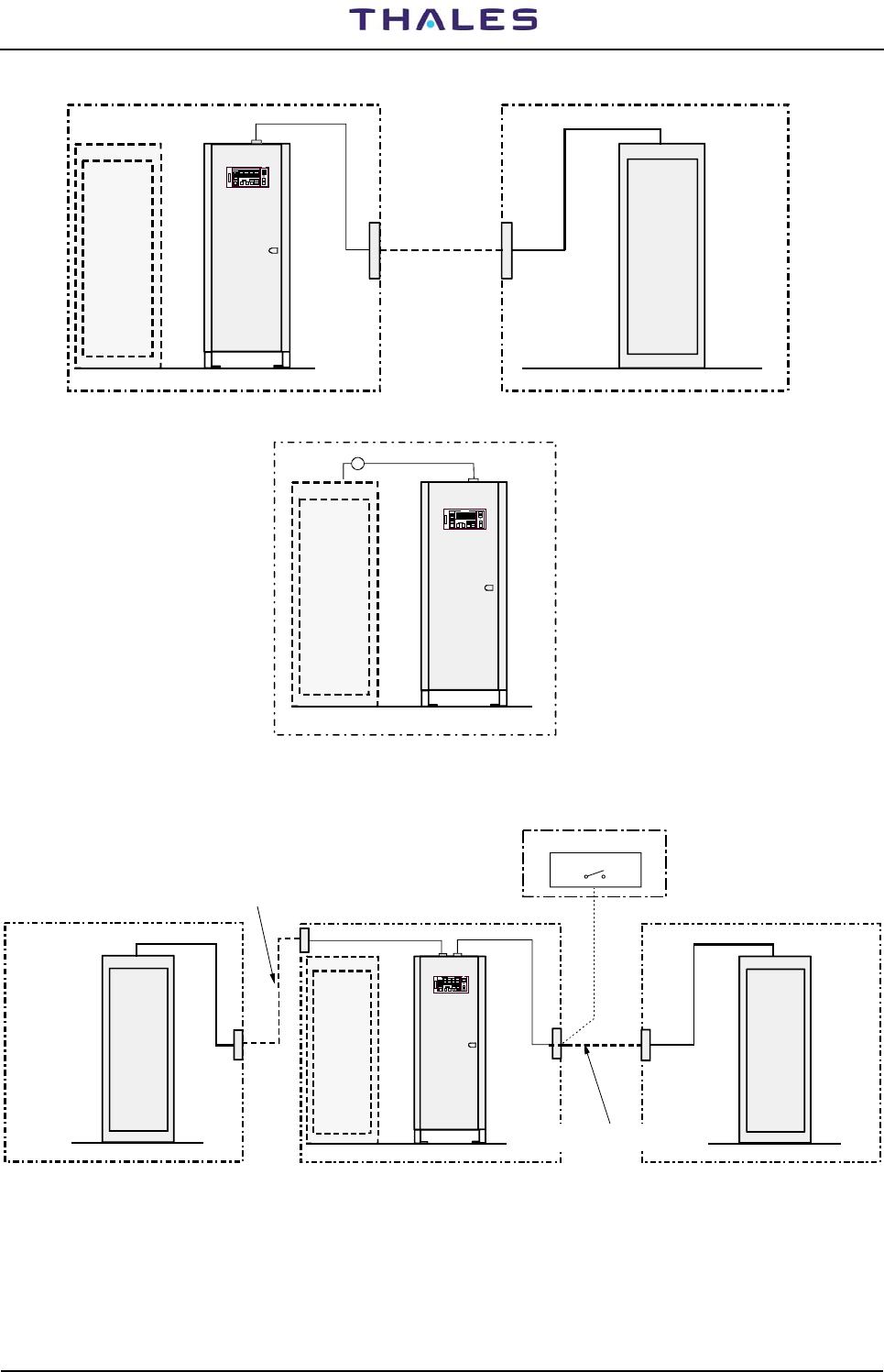
955 900 031 C DME 415/435 -Technical Manual
Vol. 1-Section 2 - Installation
2-40 THALES Italia S.p.A.- A. S. D. Vers. D, September 2005
ILS-GS ILS-LOC
DME
AF1/SK4
Shelter Shelter
cable
interface facility cable
DME - LOC Identity Connection cable
DME-INTERFACE
External connection
Identity cable
VOR or DVOR DME
AF1/SK4
Shelter
interface facility cable
DME - VOR Identity Connection cable
9
ILS-GS ILS-LOC DME
AF1/SK4
Shelter
Shelter
equip. 1
cable
interface facility cables DME-INTERFACE
ILS-LOC
Shelter
equip. 2
DME-INTERFACE
AF2/SK5
External connection
Identity cable
Switch selector
Control Tower Room
cable
DME Identity Connection cable with two LOC equipments
External connection
Identity cable
Figure 2.30. Equipment associated examples
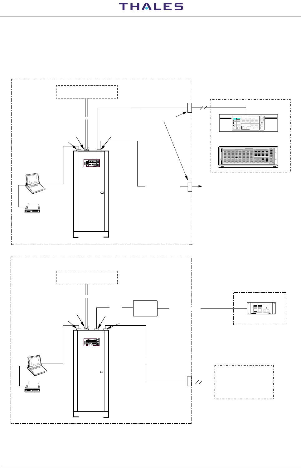
DME 415/435 -Technical Manual
Vol. 1-Section 2 - Installation 955 900 031 C
Vers. D, September 2005 THALES Italia S.p.A.- A. S. D. 2-41
2.6.9 Remote Control and Status Indicator
Typical examples of connections to remote control and repeater Main Status Indication are shows in figure
2.31. Information concerning the installation of the Remote Control is given on "RCSI or RCSE or MCS
Technical Manuals ".
DME 415/435
RS 232
(P C )
EQUIPMENT ROOM
SK1-PC
REMOTE CONTROL
RCSI 446-2
RCS I 446
EQUI PMENT R CSI
12 DETAILED STATUSMA IN STATUS
COMMAND
ENVIRONMENT Probes ALARMS
(SMOKE, TEMP., INTRUSION,
Obstruction light...)
PL3 OAUX
Input ON/OFF
parallel lines
ESD: teleph. line protection
Parallel port
Switched or dedicated
teleph. LINE To possible VHF
or other type of equipment
PL7 Telephon lines
STATUS INDICATOR
SI 446 - 2
WARNING
NORMAL
ALARM
1
ON
SIL
LAMP
TEST
EQUIPMENT STATUS SI
WARNING
NORMAL
ALARM
2
CONTROL ROOM
RS 232
Asyncronous
Converter
Interface
(P C )
EQUIPMENT ROOM
SK1-PC
ENVIRONMENT Probes ALARMS
(SMOKE, TEMP., INTRUSION,
Obstruction light...)
PL3 OAUX
Input ON/OFF
parallel port
RS 232
PL2 serial port
RS 422 (max 1km)
Parallel port
Switched or dedicated
telephon LINE
PL7 Telephon lines
Interface connected
directly on PL2 connector
DME 415/435
MAIN STAT US DET AILED ST ATUS
EQUIPMEN T
COMMAND
RC
MON 1 MON 2 TX 1 TX 2
1234567 8
CONTROL STATION
ALARM
WARNING
NORMAL
DATA COM
MAINTEN
ALARM
WARNING
NORMAL
DATA COM
MAINTEN
ALARM
WARNING
NORMAL
DATA COM
MAINTEN
ALAR M
WARNING
NOR M AL
DATA COM
MAINTEN
ALAR M
WARNING
NORMAL
DATA COM
MAINTEN
ALAR M
WARNING
NORMAL
DATA COM
MAINTEN
AERIAL
STANDBY
FAULTY
BYPASSED
ON
WARNING
FAULTY
ON ANT
ON
WARNING
FAULT Y
ON ANT
ENGAG ED
ENABL ED
MAINS OFF
ENV ALRM
ANT F TY
OTHER WARN
OP E R AT ION
WARNING
DATA CO M
ALAR M
WARNING
NORMAL
DATA COM
MAINTEN
ALARM
WARNING
NORMAL
DATA COM
MAINTEN
AER IAL
STAN DBY
FAULTY
BYPASSED
SELECT SELECT SELECT SELECT SELECT SELECT SELECT SELECT EQUIP
ON/OFF CHANGE
OVER REQUEST
RELEASE LAMP
TEST
SIL
RCSE 443
or
REMOTE CONTROL
Monitoring and Control Systems
MCS Program on PC (option)
Monitoring and Control Systems
MCS Program on PC (option)
Figure 2.31. Remote Control and Status Indications connection examples
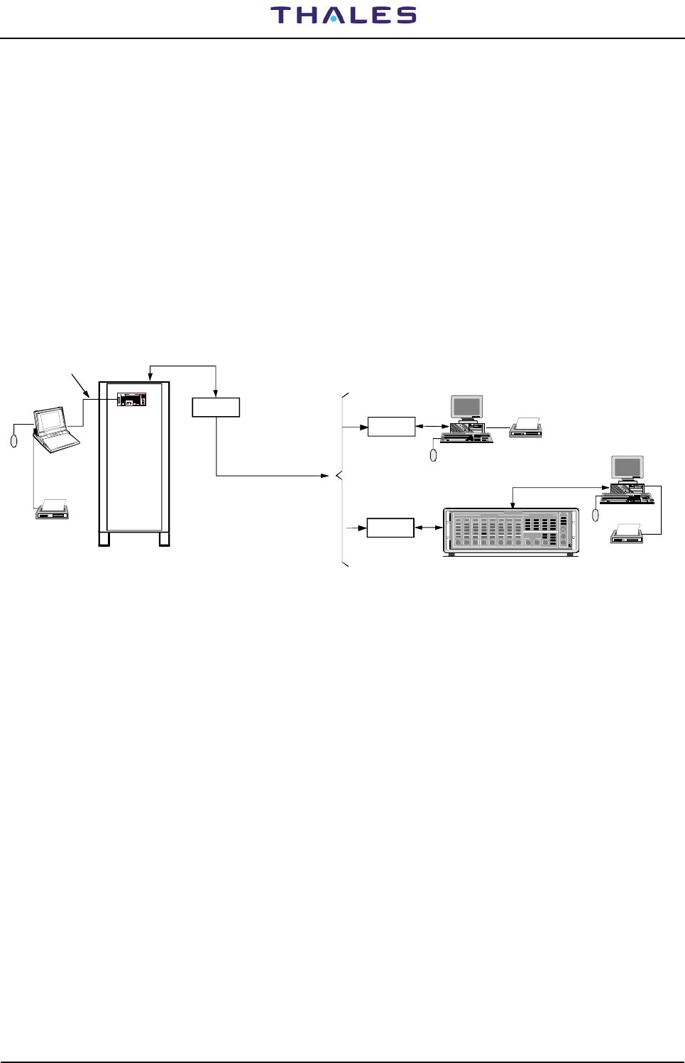
955 900 031 C DME 415/435 -Technical Manual
Vol. 1-Section 2 - Installation
2-42 THALES Italia S.p.A.- A. S. D. Vers. D, September 2005
2.6.10 PC Installation
For local mode the cable is connected to the RS-232 terminal on the front panel of the local control and
status unit (LCSU) or on SK1 connector of the I/O panel of the cabinet
In the case of remote mode, the data transfer is achieved via the modem and the remote control unit (e.g.
RCSI 446/RCSE443, see figure 2.32).
NOTE:
The procedures of program installation on PC are described in section 3 of this volume, paragraph 3.5 - and
para 3.6.
The program installation is described in Appendix sections of this volume:
− APPENDIX B-PC user WINDOWS SUPERVISOR;
− APPENDIX C-PC user WINDOWS ADRACS SUPERVISOR;
− APPENDIX D-PC user EQUIPMENT MANAGER.
CONTROL
REMOTE
MODEM
MODEM
PC "LOCALE"
(laptop or
desktop type)
DME
MODEM
RS-232
Stampante
Mouse
Mouse
(e.g.COM1)
RS-232
PC "Remote" (see *NOTE)
MAIN STATUS DETAILED STATUS
EQUIPMEN T
COMMAND
RC
MON 1 MON 2 TX 1 TX 2
12345678
CON TRO L STATION
ALARM
WARNING
NORMAL
DATA COM
MAI N T E N
ALARM
WARNING
NORMAL
DATA COM
MAINT EN
ALARM
WARNING
NORMAL
DATA COM
MAI N T E N
ALARM
WARNING
NORMAL
DATA CO M
MAI N T E N
ALARM
WARNING
NORMAL
DATA CO M
MAINT EN
ALARM
WARNING
NORMAL
DATA CO M
MAINT EN
AERIAL
STANDBY
FAULTY
BYPASSED
ON
WARNING
FAULTY
ON ANT
ON
WARN ING
FAULTY
ON ANT
ENGA GE D
ENABLED
MAI NS OF F
ENV ALRM
ANT FTY
OTHER WARN
OPER AT ION
WARNING
DATA CO M
ALARM
WARNING
NORMAL
DATA COM
MAI N T E N
ALARM
WARNING
NORMAL
DATA COM
MAI N T E N
AERIAL
STANDBY
FAULTY
BYPASSED
SEL ECT SE LECT SE LECT SE LECT SEL ECT SE LECT SELECT SE LEC T EQUIP
ON/OFF CH A N G E
OVER REQU EST
RELE A SE
LAMP
TEST
SIL
(RCSI or RCSE)
Printer
PC
Internal
or External
Internal
or External
Switched or dedicated
teleph. LINE
Printer
NOTE:
With Monitoring and Control Systems ( RCSI/RCSE not used)
is necessary to install on PC the MCS software
see *NOTE
Figure 2.32. PC connection examples
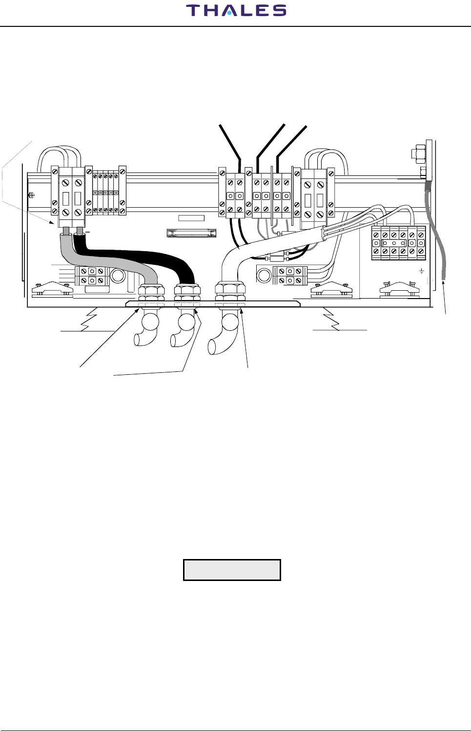
DME 415/435 -Technical Manual
Vol. 1-Section 2 - Installation 955 900 031 C
Vers. D, September 2005 THALES Italia S.p.A.- A. S. D. 2-43
2.6.11 Power supply with BCPS subrack of Frako type (optional version)
The grounding and supply connections are similar to like described in para 2.6.2 and 2.6.3. For this optional
version to refer at figures 2.33 and also at para 1.6.8.2.1 section 1 in this volume.
+BAT
ST11
+48V 2
+48V 1
+N -N
+N -N
+B -B
+B -B
-BAT
+A -A
+A -A -D
+D
+D -D -R
-R
+R
+R
2A
20A
20A
2A
NL1 L2 L3
PE
FPE
+
GND
+48 Coax.
Relay
+-
34 2 To internal cabinet bolt
of the local ground network
BATTERY cables Mains cable
Mains cable
Bush fair-lead
Battery, or esternal
48Vdc, cable
Bush fair-lead
Battery input TERMINALS and
Input external 48Vdc power supply
Figure 2.33. BCPS subrack of Frako type - Supply cables connection
2.6.11.1 External power supply 48Vdc connection (Frako subrack)
BCPS unit is equipped with the Supervisor module and without the AC/DC converters.
Connect cables 3 and 4 of table 2-1, to "± B" terminals (Fig. 2.33). Cable “2” is not used.
Configure the LCSU as described in Section 3 para. 3.2.2.1.2.3 (Aux Input 8..15), disabling the warning
messages for: MAINS/BATT, AC/DC FAULTY, PREDEPL.
NOTE: fuses F1-F2 of the printed circuit board, inside the Battery Supervisor module, must be removed.
During power supply connection: be sure the breaker of the Battery
Supervisor is OFF.
WARNING

955 900 031 C DME 415/435 -Technical Manual
Vol. 1-Section 2 - Installation
2-44 THALES Italia S.p.A.- A. S. D. Vers. D, September 2005
Page Intentionally Blank

THALES Italia S.p.A.- Air Systems Division
Description, Installation, Operation, Maintenance Reference: Vol. 1 Code 955 900 031 C
GROUND BEACON
DME 415/435
Technical Manual
VOLUME 1
Equipment description, Installation, Operation, Maintenance and PC user
Vers. D, September 2005
SECTION 3
OPERATION and USE INSTRUCTION

955 900 031 C DME 415/435 -Technical Manual
Vol. 1-Section 3 - Operation & Use
3-II THALES Italia S.p.A.- A. S. D. Vers. D, September 2005

DME 415/435 -Technical Manual
Vol. 1-Section 3 -Operation & Use Ref. 955 900 031 C
Vers. D, September 2005 THALES Italia S.p.A.- A. S. D. 3-a
Table of CONTENTS
Paragraph Page
SECTION 3............................................................................................................................................3-1
OPERATION and USE INSTRUCTION ...................................................................................3-1
GENERAL .............................................................................................................................................3-1
3.1 LOCAL CONTROL and INDICATION PANEL .........................................................................3-1
3.2 LCSU unit Configuration Procedure .........................................................................................3-6
3.2.1 LCSU PARAMETER CONFIGURATION..........................................................................3-6
3.2.1.1 Program install on PC.......................................................................................................3-6
3.2.1.1.1 From floppy disk................................................................................................................3-6
3.2.1.1.2 From CDROM...................................................................................................................3-6
3.2.2 LCSU CONFIGURATION PROCEDURE.........................................................................3-7
3.2.2.1 Main Menu ........................................................................................................................3-7
3.2.2.2 System Overview..............................................................................................................3-8
3.2.2.3 LCSU Configuration..........................................................................................................3-9
3.2.2.3.1 LCSU Site Code................................................................................................................3-9
3.2.2.3.2 User Configuration............................................................................................................3-10
3.2.2.3.3 Parallel Input Definition.....................................................................................................3-13
3.2.2.3.4 Parallel Output Definition ..................................................................................................3-18
3.2.2.3.5 Commands equipments list .............................................................................................3-24
3.2.2.3.6 User Connection Parameters ...........................................................................................3-25
3.2.2.3.7 LCSU Site Equipment Configuration ................................................................................3-26
3.2.2.3.8 LCSU Site Parameter .......................................................................................................3-27
3.2.2.3.9 REU parameters ...............................................................................................................3-27
3.2.2.3.10 Export Configuration Data ................................................................................................3-28
3.2.2.3.11 Import Configuration Data.................................................................................................3-28
3.2.2.3.12 Hardware Test ..................................................................................................................3-28
3.2.2.3.13 Test of Parallel Input Port .................................................................................................3-29
3.2.2.3.14 Test of Parallel Output Port ..............................................................................................3-30
3.2.2.3.15 Test of Serial Lines ...........................................................................................................3-32
3.2.2.4 Test Data Consistency......................................................................................................3-33
3.2.2.5 To Exit from the Program..................................................................................................3-33
3.2.2.6 Modem Configuration........................................................................................................3-34
3.2.3 File Configuration in Supervisory Program.......................................................................3-35
3.3 INDICATORS ON THE MODULES..........................................................................................3-36
3.4 I/O FUNCTIONING...................................................................................................................3-39
3.5 USER SOFTWARE INSTALLATION on PC ............................................................................3-39
3.5.1 General .............................................................................................................................3-39
3.5.2 PC user programs INSTALLATION ..................................................................................3-40
3.5.2.1 PC REQUIREMENTS.......................................................................................................3-41
3.6 INSTALLATION on PC OF USER OPERATING PROGRAM..................................................3-41
3.6.1 "PC Supervisor" program composition .............................................................................3-42
3.6.1.1 Windows SuperVisor (WINSV) .........................................................................................3-42
3.6.1.2 WinSv ADRACS Windows Supervisor..............................................................................3-42
3.6.1.3 Windows DME/N Equipment Manager - WINDME/N-32..................................................3-42
3.6.1.4 MCS programming............................................................................................................3-42
3.7 First SWITCHING ON...............................................................................................................3-43
3.8 POWER OFF PROCEDURE....................................................................................................3-44

955 900 031 C DME 415/435 -Technical Manual
Vol. 1-Section 3 - Operation & Use
3-b THALES Italia S.p.A.- A. S. D. Vers. D, September 2005
List of FIGURES
Figure Page
Figure 3.1. LCSU Front panel............................................................................................................... 3-1
Figure 3.2. Main Menu..........................................................................................................................3-7
Figure 3.3. System Overview................................................................................................................3-8
Figure 3.4. Configuration menu ............................................................................................................ 3-9
Figure 3.5. Site Code............................................................................................................................3-9
Figure 3.6. Users Configuration............................................................................................................3-10
Figure 3.7. Users Configuration Table example ...................................................................................3-13
Figure 3.8. Parallel Input Definition....................................................................................................... 3-13
Figure 3.9. Parallel Input....................................................................................................................... 3-14
Figure 3.10. Input command Logic .......................................................................................................3-14
Figure 3.11. Example of Beacon Site Environment.............................................................................3-15
Figure 3.12.a. Aux input 8...15 - Configuration Examples....................................................................3-15
Figure 3.12.b. Additional input 0.. 3 - Configuration Examples ............................................................ 3-16
Figure 3.13. Parallel Output Definition..................................................................................................3-18
Figure 3.14. Output command Logic .................................................................................................... 3-19
Figure 3.15.a. Parallel Output Definition - OUT 0................................................................................. 3-19
Figure 3.15.b. Parallel Output Definition - OUT 1................................................................................. 3-19
Figure 3.15.c. Parallel Output Definition - OUT 2.................................................................................3-20
Figure 3.15.d. Parallel Output Definition - OUT 3................................................................................. 3-20
Figure 3.15.e. Parallel Output Definition - AUX OUTPUT O..7 ........................................................... 3-20
Figure 3.16. Parallel Output Definition - Buzzer ...................................................................................3-21
Figure 3.17. User Connection Parameters ...........................................................................................3-25
Figure 3.18. LCSU Site equipment menu.............................................................................................3-26
Figure 3.19. Status of LCSU Site equipment........................................................................................3-26
Figure 3.20. LCSU Site parameter .......................................................................................................3-27
Figure 3.21. Reu Parameters ...............................................................................................................3-27
Figure 3.22. Export LCSU configuration data.......................................................................................3-28
Figure 3.23. Import LCSU configuration data ....................................................................................... 3-28
Figure 3.24. Hardware Test .................................................................................................................. 3-28
Figure 3.25. Test of Parallel Input Port.................................................................................................3-29
Figure 3.26. Test Control Input.............................................................................................................3-29
Figure 3.27. Test Aux Input .................................................................................................................. 3-30
Figure 3.28. Test Additional Input.........................................................................................................3-30
Figure 3.29. Test of Parallel Output Port ..............................................................................................3-30
Figure 3.30. Test Output port 1.............................................................................................................3-31
Figure 3.31. Test Aux Output................................................................................................................3-31
Figure 3.32. Test Buzzer.......................................................................................................................3-32
Figure 3.33. Test of Serial Lines........................................................................................................... 3-32
Figure 3.34. Testing of Port Number ....................................................................................................3-32
Figure 3.35. Test Data Consistency .....................................................................................................3-33
Figure 3.36. System control via PC (example) ....................................................................................3-35
Figure 3.37. LED indicators on transponder modules .......................................................................... 3-37
Figure 3.38. LED indicators on 1 kWp RF amplifiers and AFI modules ...............................................3-38
Figure 3.39. LED indicator on AC/DC power supply module and on the MODEM ..............................3-38
Figure 3.40. Examples of PC user programs with DME stand alone ...................................................3-40
Figure 3.41. Examples of PC user programs in VOR-DME system ..................................................... 3-40
Figure 3.42. Examples of PC user programs with multi-sites............................................................... 3-41

DME 415/435 -Technical Manual
Vol. 1-Section 3 -Operation & Use Ref. 955 900 031 C
Vers. D, September 2005 THALES Italia S.p.A.- A. S. D. 3-c
List of TABLES
Table Page
Table 3-1. Controls and Indications on the Front panel of LCSU (Main Status)...................................3-2
Table 3-2. Controls and Indications on the Front panel (Detailed status).............................................3-3
Table 3-3. Controls and Indications on the Front panel (Control, Commands, Station) .......................3-4
Table 3-4. Controls and Indications on the Front panel (LCSU status) ................................................3-5
Table 3-5. List of the input Identifier......................................................................................................3-17
Table 3-6. List of the Detailed Status Indications..................................................................................3-22
Table 3-7. List of Equipment Status ......................................................................................................3-23
Table 3-8. List of the Indications from LCSU to User............................................................................3-24
Table 3-9. Equipment Commands list ...................................................................................................3-24
Table 3-10. LEDs Indicators on the Front of every modules.................................................................3-36

955 900 031 C DME 415/435 -Technical Manual
Vol. 1-Section 3 - Operation & Use
3-d THALES Italia S.p.A.- A. S. D. Vers. D, September 2005
Page Intentionally Blank
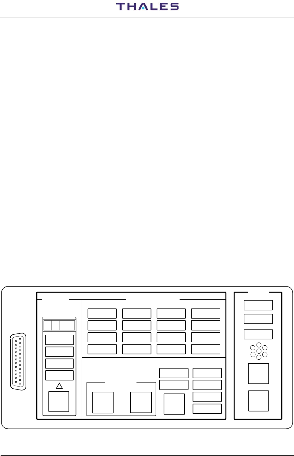
DME 415/435 -Technical Manual
Vol. 1-Section 3 - Operation & Use 955 900 031 C
Vers. D, September 2005 THALES Italia S.p.A.- A. S. D. 3-1
SECTION 3
OPERATION and USE INSTRUCTION
GENERAL
For local operation, only a few functions are operable with the Control and Indication Panel (LCSU). The
configuration, alignment procedure and the maintenance are performed with a locally connected PC via a
user program "WINSV Supervisor" installed on a PC (typical connections example in section 1 on Vol.1 of
this technical manual).
In the normal case standard of remote operation, is carried out via a control interface, connected at a
Remote Control and Status Indicator unit (typical connections example in section 1 on Vol.1 of this technical
manual).
3.1 LOCAL CONTROL AND INDICATION PANEL
The local controls and indicators are to be found on the front panel of INC Module of the LCSU unit only,
located at the front door.
The Control and Indication Panel is subdivided into the following fields:
• MAIN STATUS
• DETAILED STATUS
• COMMAND
• CONTROL
• STATION
• LCSU
The individual fields contain indications and keys. Only those indications currently in message status are lit
up and thus legible. This ensures that misinterpretations are avoided. The meaning of the indications and
keys in the various fields are described in the following paragraphs.
These controls and indicators are listed in tables 3-1 and shown in figure 3.1.
MON 1 MON 2 TX 1 TX 2
DETAILED STATUS LCSU
LOCAL CONTROL & STATUS UNIT
CONTROL STATION
ALARM
WARNING
NORMAL
DATA COM
ALARM ALARM
WARNING WARNING
WARNING
COMMAND
STBYALRM STBYALRM
ON ON
FAULTY FAULTY FAULTY FAULTY
BYPASSED BYPASSED ON ANT ON ANT
OPERATION
ENGAGED
ENABLED
MAINS OFF
ENV ALRM
ANT FTY
OTHER WARN
CHANGE
OVER
EQUIP
ON/OFF
SELECT LAMP
TEST
REQUEST
RELEASE
SIL
DATA COM
PC
RS232 RD1
RD31
RD30
RD29
RD32
RD11
RD26
RD28
RD21
RD12
RD27
RD22
RD23
RD13
RD25
RD24
RD18
RD33
RD17
RD14
RD19
RD9
RD15
RD10
RD5
RD20
RD8
RD6
RD7
RD16
RD4
S1
I6
I5
I4
I3
I2
I1
MAIN
STATUS
Figure 3.1. LCSU Front panel

955 900 031 C DME 415/435 -Technical Manual
Vol. 1-Section 3 - Operation & Use
3-2 THALES Italia S.p.A.- A. S. D. Vers. D, September 2005
Table 3-1. Controls and Indications on the Front panel of LCSU (Main Status)
Definition Color
of indicator
Reference
to Fig. 3.1 DESCRIPTION
MAIN STATUS field Field with display always active
PC RS232
connector - (SK6)
Serial RS 232 connector that permits insertion of the cable of the
serial line to interconnect a local PC. This connector is “pin to pin”
parallel of SK1 located on the I/O Panel at top end of equipment.
Display - RD1
Text display: N° 4 programmable digit alphanumeric, electronic dataplate
that makes it possible to highlight the equipment code or identification of the
site. These indicators are managed and stored with the configuration
program.
ALARM Red RD31
Normally OFF.
In AUTOMATIC mode, indicates shut-down of the beacon.
In MANUAL mode, the led is always ON because the radiated signal not is
longer guaranteed.
WARNING Yellow RD30
Normally OFF.
ON: Indicates that the beacon is affected by:
- a secondary alarm of the transponder on antenna;
- a faulty DMD or DPR irregular functioning of these;
- a faulty monitor;
- alarm on the transponder in ST-BY;
- mains failure;
- beacon OFF;
- other general faults.
NORMAL Green RD29
Normally ON.
No ALARMS or WARNINGS have been found.
DATA COM Red RD32
Normally OFF.
Indication of errors or faults in the serial communication system between
equipment and LCSU.
- Green RD11
Acknowledgement for SELECT key - Triangular shaped that indicates
selection of enabling to highlight detailed states by the local operator.
SELECT
key
- I1 Selection key to disable and enable detailed status indications.

DME 415/435 -Technical Manual
Vol. 1-Section 3 - Operation & Use 955 900 031 C
Vers. D, September 2005 THALES Italia S.p.A.- A. S. D. 3-3
Table 3-2. Controls and Indications on the Front panel (Detailed status)
Definition Color
of indicator
Reference
to Fig. 3.1 DESCRIPTION
DETAILED STATUS field This field must be enabled by the operator using the “SELECT” key
MON 1
ALARM Red RD26 Normally OFF.
Indicates that Monitor 1 has found one or more of the parameters of the
transponder, on antenna, out of tolerance.
MON 1
STBY
ALARM
Yellow RD28
Normally OFF.
Indicates that Monitor 1 has found an error or defect in the transponder on
the dummy load.
MON 1
FAULTY Yellow RD21
Normally OFF.
Indicates a fault due to Monitor 1 or that Monitor 1 has not passed the tests
of its own self-check correctly.
MON 1
BYPASSED Yellow RD12
This indicator is ON when the operator sets the beacon to MANUAL mode.
In this case, the intervention functions by Monitor 1 are ignored. It switches
on, together with MON2 BYPASS (RD13).
MON 2
ALARM Red RD27
Normally OFF.
Indicates that Monitor 2 has found parameters of the transponder on
antenna out of tolerance.
MON 2
STBY
ALARM
Yellow RD22
Normally OFF.
Indicates that Monitor 2 has found an error or defect in the transponder on
the dummy load.
MON 2
FAULTY Yellow RD23
Normally OFF.
Indicates a fault due to Monitor 2 or that Monitor 2 has not passed the tests
of its own self-check correctly.
MON 2
BYPASSED Yellow RD13
This indicator is ON when the operator sets the beacon to MANUAL mode.
In this case, the execution functions by Monitor 1 are avoided. It switches
on, together with MON1 BYPASS (RD12).
TX 1
ON Green RD25
Normally ON.
Transmitter 1 has received the ON OPERATING command and is operating
correctly, providing power either on antenna or on dummy load.
TX 1
WARNING Yellow RD24 Normally OFF.
Indicates faults or secondary alarms (one or more) found on transponder 1.
TX 1
FAULTY Red RD18
Normally OFF.
Indicates a primary alarm on transponder 1. TRX 1 is shut down by
monitor system due to an alarm
TX 1
ON ANT Green RD33 Indication that makes it possible to check whether the transponder is on
antenna. In this case, it indicates transponder 1 on antenna: therefore,
transponder 2 is connected to the dummy load.
TX 2
ON Green RD17 Normally ON. - Transmitter 2 has received the OPERATING command and
is operating correctly providing power either on antenna or on dummy load.
In single configuration, it is always in OFF
TX 2
WARNING Yellow RD14 Normally OFF. - Indicates faults or secondary alarms (one or more) found
on transponder 2. In single configuration, it is always in OFF
TX 2
FAULTY Red RD19 Normally OFF.
Indicates a primary alarm on transponder 2. TRX 2 is shut down by
monitor system due to an alarm. - In single configuration, it is always in
OFF
TX 2
ON ANT Green RD9 Indication that makes it possible to check whether the transponder is on
antenna. In this case, it indicates transponder 2 on antenna: therefore,
transponder 1 is connected to the dummy load. In single configuration is on
when the TX1 is on Dummy-load

955 900 031 C DME 415/435 -Technical Manual
Vol. 1-Section 3 - Operation & Use
3-4 THALES Italia S.p.A.- A. S. D. Vers. D, September 2005
Table 3-3. Controls and Indications on the Front panel (Control, Commands, Station)
Definition Color
of indicator
Reference
to Fig. 3.1 DESCRIPTION
CONTROL Field Field with display enabled by SELECT key
ENGAGED Yellow RD15 Indicates that one of the operators is controlling the equipment, through
Local PC or other Remote Control (priority).
ENABLED Green RD10 Indicates that the local operator using the «REQUEST-RELEASE - I4» key
has acquired control of beacon commands. It flashes during the execution
of the ON/OFF and CHANGE-OVER commands.
REQUEST
RELEASE
key
- I4
Press the REQUEST/RELEASE key to request control and wait for the
ENABLED indication. Button with whom the local operator (priority) can
enable or release equipment controls. This action depending of "control
superseding" parameter configuration:
Disable = overridden never on the user in operation
Enable = overridden always on the user in operation
Priority = overridden only if preset is better of priority on the user
in operation
On receiving the request, the beacon changes to AUTOMATIC mode.
Perform the desired command on/off or change over of transponder
by pressing the corresponding key EQUIP ON/OFF or CHANGE
OVER. Press the REQUEST/RELEASE key again to release the
control for PC or Remote Control. The ENGAGED indication is OFF
when the control taken by the local control.
COMMAND Field
EQUIP
ON/OFF
key
- I2 Key that makes it possible to switch the beacon ON and OFF. This button is
enabled by “REQUEST/RELEASE” key.
CHANGE
OVER
key
- I3
It is used to change over the conditions of operating on antenna by one or
the other transponder. Therefore, the transponders connected to the dummy
load will invert their role. This key is enabled by “REQUEST/RELEASE” key.
The transponder on antenna conditions can be deduced from the indications
of RD33 and RD9 (ON ANT) for transponder 1 and 2 respectively.
STATION field
MAINS OFF Yellow RD5
Indicates a mains failure (black-out or mains power off) and that the
equipment is operating with the back-up batteries.
ENV ALRM Red RD20 Indicates that one or more site signals are in alarm condition. For example
the signals indicating: smoke, intrusion, high temperature or failure of
obstacle lights, etc.
ANT FTY Red RD8
Not used (only relevant for TACAN and NDB).
OTHER
WARNING Yellow RD6
Normally OFF.
Extra general type indication of any alarm conditions that may not
necessarily put the equipment out of service.
The indication is associated to the WARNING indication of MAIN STATUS.

DME 415/435 -Technical Manual
Vol. 1-Section 3 - Operation & Use 955 900 031 C
Vers. D, September 2005 THALES Italia S.p.A.- A. S. D. 3-5
Table 3-4. Controls and Indications on the Front panel (LCSU status)
Definition Color
of indicator
Reference
to Fig. 3.1 DESCRIPTION
LCSU Section Section with display always active
OPERATION Green RD16
Normally ON.
Indicates correct functioning of the permanent and continuous self check of
the CSB module as regards both its own HW circuits and SW programming.
Also assures continuous checking of the correctness of the +5VDC voltage
via the CSB watchdog circuit.
WARNING Yellow RD7
Normally OFF.
Indicates any alarms in the CSB module such as incorrect RTC (Real Time
Clock).
DATACOM Red RD4 Not used.
BUZZER S1
Audible alarm that informs the operator of a primary alarm on both
transponders and is activated concurrently with the MAIN STATUS ALARM
message.
The buzzer sounds until it is reset manually with the “SIL” button.
In MANUAL Mode, the buzzer is not activated.
SIL key I6 Buzzer reset pushbutton.
LAMP
TEST
key
I5
Checks correct functioning of the lamps of the INC module and efficiency of
the buzzer for optical and acoustical testing purposes. This action
envisages switching off all the leds, switching on again one at a time and
then reset to the initial condition. At power-on, this test is carried out
automatically.
On CSB module PBA (printed board assembly) the following LED and keys are placed:
- green LED, indication of data on the transmission serial line
- green LED, indication of data on the receiver serial line
- green LED, watch-dog OK
- Key of reset of the CPU
The layout of module CSB is in section 5 - Maintenance and Repair - of this volume

955 900 031 C DME 415/435 -Technical Manual
Vol. 1-Section 3 - Operation & Use
3-6 THALES Italia S.p.A.- A. S. D. Vers. D, September 2005
3.2 LCSU UNIT CONFIGURATION PROCEDURE
In this paragraph, feel shown examples of the screens which will be to visualize during the procedure of
configuration. The notes on the screens are of comment and memorandum during the phases of the
procedure.
The procedure of configuration of unit LSCU can be active even when the DME is operational, since the
radio beacon is managed by a specific program.
3.2.1 LCSU PARAMETER CONFIGURATION
This utility program is necessary of the all LCSU unit parameters configuration
3.2.1.1 Program install on PC
Normally the LCSU is supplied as configuration standard
3.2.1.1.1 From floppy disk
Make sure WINDOWS operating system is installed on PC
The “Util ” floppy disk configuration TERMINAL EMULATOR program containing these files:
− install.exe installation program,
− zutil.exe program to configure the modem through the Modem.exe file,
− emul.exe terminal emulator program to enable the LCSU unit configuration including the serial
and parallel lines (as well as the operation checks of all these lines through the specific “Hardware
test” program).
readme.doc text file with the information concerning the installation of the files.
Load the "UTIL" program provided on the 3,5" diskette onto the PC hard disk
− Insert the “ disk UTIL” into the 3,5" floppy disk drive (usually “a:”);
− Type the A: command and press the ENTER key;
− Type <install c:\<name> > and press the ENTER key;
<name> is an indication and the actual name can be established by the user. "c:" is the usually drive
where the program is installed on hard disk.
3.2.1.1.2 From CDROM
Make sure WINDOWS operating system is installed on PC
The program is provided on CDROM complete of program "Terminal emulator configuration" in the directory
"WinSv" and includes the file:
emul.exe program "terminal emulator" to enable the configuration of LCSU unit, included the lines
parallel and serial, by the program "Hardware test"
Load the program emul.exe on the hard disk as it is known as in the section of the APPENDIX B, in this
volume.

DME 415/435 -Technical Manual
Vol. 1-Section 3 - Operation & Use 955 900 031 C
Vers. D, September 2005 THALES Italia S.p.A.- A. S. D. 3-7
3.2.2 LCSU CONFIGURATION PROCEDURE
To modify the LCSU configuration parameters connect a PC to connector SK1 on the I/O panel (or directly
to the front panel of the LCSU unit named PC RS232)
This paragraph describes some video page examples that are displayed during the configuration procedure.
The notes concerning some video pages are remarks and memorandum to be followed when loading the
configuration procedure.
The LCSU configuration procedure can also be activated when the DME is operating, since the beacon is
managed by a specific program.
To load the program, proceed as follows:
− run the “EMUL.exe” program from the PC;
− press the "I1" RESET push-button on the PBA of CSB module (reached from the back of the
equipment front door);
− when the starting video page is displayed, press the keyboard space bar at least three times within a
few seconds to access the configuration mode;
− if access is not obtained with the first configuration video page, repeat the RESET operation;
− perform the configuration procedure following the instructions displayed in the menu;
− after configuration, save the variations in EEPROM; it is suggested to save the new data on a back-
up diskette.
− Before running the supervisor program change the parameters in the config.ini file according to
LCSU configuration.
3.2.2.1 Main Menu
Figure 3.2 shows the main video page of the configuration program. Besides the options indicated, it is also
possible to return to the previous menu by pressing the ESC key.
LCSU Maintenance Program MAIN MENU
[1] System Overview
[2] LCSU Configuration
[3] Hardware test
[0] END
Select:
F1 - Import Data F2 - Export Data F5 - Clear Video F10 - Quit
Figure 3.2. Main Menu
If, when starting up the program, an EEPROM failure is detected (faulty or containing data no longer valid),
the following message is displayed at the bottom of the video page:
Invalid configuration data, press a key to load default parameters.
NOTE: F1, F2, F5, F10 are key of PC keyboard - ESC = previous menu

955 900 031 C DME 415/435 -Technical Manual
Vol. 1-Section 3 - Operation & Use
3-8 THALES Italia S.p.A.- A. S. D. Vers. D, September 2005
3.2.2.2 System Overview
Selecting option [1] from the Main Menu the example video page shown in figure 3.3 is displayed.
The goal of this screen is to show to the operator some important feature of the software:
− Internal NAME of the equipment (CODE & MANUFACTURER);
− Programmable COMMUNICATION line;
− Number of the STATES and COMMANDS allowed for each equipment;
For each equipment:
− Number of History DATABASE provided;
− Number of DIGITAL I/O specific for the equipment.
These informations are useful during configuration job.
All the informations of this screen are fixed.
LCSU Maintenance Program System Overview
V1.01-DMXXU101
Name Code States Dbases Dig_out
| | | | |
| | | | |
Index | Mnfct | Comms | Cmds | Dig_in |
| | | | | | | | | |
--- ---------------- --- --- --- --- --- --- --- ---
[0] LCSU Unit 0 0 0 48 16 1 0 0
[1] ANS-DMEN 415/435 1 1 0 80 3 4 12 0
Press <ESC> to exit
F1 - Import Data F2 - Export Data F5 - Clear Video F10 - Quit
Figure 3.3. System Overview
V1= actual version of software
The items have the following meanings:
Index: List of equipment managed by LCSU
Name: Managed equipment codes
Mnfct: Manufacturer
0 = LCSU System
1 = ANS (Thales)
Code: Equipment code
0 = LCSU
1 = DME/N
2 = DME/P
Comms: Number of Communications Serial Port used
LCSU = 0 (No Port used)
DME = 0
States: Quantity of state messages available
LCSU = 48
DME = 80

DME 415/435 -Technical Manual
Vol. 1-Section 3 - Operation & Use 955 900 031 C
Vers. D, September 2005 THALES Italia S.p.A.- A. S. D. 3-9
Cmds: Max. quantity of commands managed
LCSU = 16
DME = 3
Dbases: Data Bases (History) associated to the equipment
LCSU = 1
DME = 4
Dig_in: Parallel input lines - Number of lines for beacon management
LCSU = 0
DME = 12
Dig_out: Parallel output lines - Number of lines for beacon management
LCSU = 0
DME = 0
3.2.2.3 LCSU Configuration
This screen groups the entire Submenu configuring the software and two option (EXPORT & IMPORT) to
save SAVE/RESTORE the changes made.
Selecting option [2] on the Main Menu displays the page shown in figure 3.4.
LCSU Maintenance Program Configuration
[1] LCSU Site code
[2] Users configuration
[3] Parallel input definition
[4] Parallel output definition
[5] User connection parameters
[6] LCSU site equipment configuration
[7] LCSU site parameters
[8] Reu parameters
[9] Export LCSU configuration data
[10] Import configuration data
[0] Return
Select:
F1 - Import Data F2 - Export Data F5 - Clear Video F10 - Quit
Figure 3.4. Configuration menu
3.2.2.3.1 LCSU Site Code
Select option [1] on the “Configuration” page to enter the beacon or site identity code as shown in figure 3.5.
This screen allows the operator to change the SITE name, which is the name used by all the users (PC, RCSI
446 or RCSE445, SI 446) to communicate with the DME.
Only CAPITAL letters and DIGIT are allowed.
LCSU Maintenance Program LCSU Site code
LCSU Site code
THAL
LCSU code (maximum 4 chars allowed):
F1 - Import Data F2 - Export Data F5 - Clear Video F10 - Quit
Figure 3.5. Site Code

955 900 031 C DME 415/435 -Technical Manual
Vol. 1-Section 3 - Operation & Use
3-10 THALES Italia S.p.A.- A. S. D. Vers. D, September 2005
3.2.2.3.2 User Configuration
Selecting option [2] from the “Configuration” menu displays, the example page shown in figure 3.6.
LCSU Maintenance Program Users configuration
Mode Com Port Attr Bps Prot Phone Number Status
User | Ident | | Modem | | timeout | Syn Ctr Init M/S Dual
| | | St Ad Type | | | | | All | Hs | S/D | usr
--- ----- ---- -- -- ---- - ----- -- -------------------- - - - - - - -- -
[1] Rs232 LCPC 1 5 9600 10 M
[2] Rs232 RMPC 2 5 9600 10 M
[3] Dis
..
..
[10] Dis.
User number: 1
F1 - Import Data F2 - Export Data F5 - Clear Video F10 - Quit
Figure 3.6. Users Configuration
This screen defines the parameters needed to manage the communication with the user:
− Kind of connection (RS232, Dedicated, switched, party line);
− Communication parameter (Port, Baud Rate, Protocol timeout);
− Identifier of the User;
− Kind of Modem (internal, external);
− Dialing parameters (Phone number and call logic) meaningful for switched line only;
− Master/Slave parameter (Party line only).
For each kind the connection, are to configure:
• User name
Identifier of user. It is the NAME of the user known everywhere in the network.
• Mode: Connection modes possible for each user
0 = Dis. (disabled: as if non existent)
1 = RS232C (type of serial line)
2 = Ded.Call (dedicated telephone line via modem in “originate” mode)
3 = Ded.Answ. (dedicated telephone line via modem in “answering” mode)
4 = switched
5 = Party line
• Ident: Identity code name of user (max. 4 alphanumeric characters).
• Com Port (Communication Port):
Valid values are from 1 to 3 (CH1, CH2 and CH3). Port 4 to 6 are reserved for internal use of
equipment.
Port 1 is generally used for local connection (line maintenance PC), Port 2 and 3 are generally used
with remote connection trough Modem (switched line, dedicated line or party line).
• St : Status Request only with switched line modems - Changing any bit of the status word – Y (yes)
the user is called upon a change of one of the main states of the equipment, N (no) in case of
equipment state variations the user is not called for updating

DME 415/435 -Technical Manual
Vol. 1-Section 3 - Operation & Use 955 900 031 C
Vers. D, September 2005 THALES Italia S.p.A.- A. S. D. 3-11
• Ad: This is a communication port used in addition to the other when the customer requires the
redundancy of the communication line. Therefore is possible to communicate with the same user
on two different lines. The additional port is used only if the first port is wrong.
A 0 value disable the line redundancy.
• Modem type: EX= External; LGM=Logem internal
• Attr Attribute
1 = Displays the states of equipment and connections; 2 = Reserved; 3 = Enables the operator to
equipment commands control; 4 = Reserved; 5 = Enables database reset and date updating
• Bps: Baud rate - Transmission rate selection (only RS232) 1:300, 2:1200, 3:2400, 4:4800, 5:9600,
• Protocol timeout
Maximum waiting time during data exchange between LCSU and user: typical 10 seconds (1 to 30 s
allowed)
• Phone Number : User phone number, only switched line (maximum 20 digits)
• Status
Syn: Synthetic - Variation of at least one of synthetic states (Normal, Warning, Alarm,
Communication faulty). - Y = (yes) it is called at every user state variation.
All: Y = (yes) the user is called whenever there is a change of one of the
equipment fundamental states. N = (no) if there is a variation in the equipment state the
user is not called for updating.
Ctr : Control - selection Y=(yes): the consumer will be called every time that another consumer
takes or liberates the control of the equipment. Selection N=(no): that consumer won't be
advised when another consumer acquire or liberated the control. Up
Hs: Database updating - Y = (yes) the authorized user is called by LCSU for a variation in the
database.
Init : Initialization (M = Mandatory, O= Optional) Recommended value: M
M/S : Definition of party-line use, of the network communication protocol (M = master, S = Slave, 0
to 9 = slave address)
Dual usr: Dual user. Enable the user redundancy.
For instance, may have two PC's redundant in the Remote site. It's sufficient to update all
only. The other PC may get the data from first.
In case of call the LCSU tries to communicate with the first PC; in case of wrong connection, it
tries with the dual user. This avoid loss of data in the switching network isn't good .
A "S" value means user redundancy disabled
A "D" value means user redundancy enabled
Dual user number. It defines the Dual user. This value must be get from the column "User" of
the screen
The allowing information needed to configure the software depends on the kind of connection, as follows:
Ö RS 232
The connection between the DME and the user is made through a serial line RS232. In general, this mode
is used when the user is on maintenance PC or on RCSI in the site.
Ö Dedicated call (direct call)
The connection between the DME and the user is made trough a Modem programmed in ORIGINATE
mode. In general, the user is a RCSI. (modem type: desk external LGM Internal (only LOGEM 28,8)
The parameters needed to make the configuration are:
• Baud rate
1:300, 2:1200, 3:2400, 4:4800, 5:9600

955 900 031 C DME 415/435 -Technical Manual
Vol. 1-Section 3 - Operation & Use
3-12 THALES Italia S.p.A.- A. S. D. Vers. D, September 2005
Ö Dedicated Answer (direct reply)
The connection between the DME and the user is made trough a Modem programmed in answer
mode
The parameters needed to make the configuration are the same as dedicated call mode.
Ö Switched line
The connection between the DME and the user is made trough a Modem programmed in Switched
mode.
The parameters needed to make the configuration are the following:
− Additional port (Ad)
This is a communication port used in addition to the other when the customer requires the
redundancy of the communication line. Therefore is possible to communicate with the same
user on two different lines. The additional port is used only if the first port is wrong.
A 0 value disable the line redundancy.
− Modem kind
External: a desk Modem
LOGEM: an internal Modem (only "Logem 28,8" is supported).
− Phone number
Phone number of the user: 18 characters are allowed
− Call logics: they define which the LCSU must call the ignore user. Syn, All, Ctr, Hs, Dual user:
definitions described status above
Ö Party line. This kind of line is used when the DME is collocated with many equipment (in general
these of an ILS). All linked to a remote user using a multi point connection.
The parameters needed to make the configuration are the following:
− User Mater/Slave
It defines which is the Mater of the communication, in general the user. A "M" means user is
master (this is the suggested value), an "S" means user is slave.
− Slave Address
It define the address of the slave (from 0 to 9). If the user is Master, this is the Address of the
DME, else is the Address of the Remote
The value to set depends on the configuration made on Remote Site.
The final data for each “user” option considered, has been entered in fig. 3.7 video page. The data is shown
in sequence each time the operator enters the correct reply based on the requests sent out by the program
(in bold type). If the operator gives a wrong reply, the sequence must be repeated starting from the request
for “user number”.
The control priority is intended as the possibility to exclude the operators of the subsequent “user” from the
equipment control (an operator excluded by another with higher priority has to wait until the latter has
finished before being able to have control of the equipment). The priorities have the following order of
importance:
1 = LCSU
2 = Local PC
3 = Remote PC and any other RCSI/RCSE
The higher priority is assigned to the “user” associated to the lower number

DME 415/435 -Technical Manual
Vol. 1-Section 3 - Operation & Use 955 900 031 C
Vers. D, September 2005 THALES Italia S.p.A.- A. S. D. 3-13
LCSU Maintenance Program Users configuration
Mode Com Port Attr Bps Prot Phone Number Status
User | Ident | | Modem | | timeout | Syn Ctr Init M/S Dual
| | | St Ad Type | | | | | All | Hs | S/D | usr
--- ----- ---- -- -- ---- - ----- -- -------------------- - - - - - - -- -
[1] Rs232 LCPC 1 5 9600 10 M
[2] Rs232 RMPC 2 5 9600 10 M
[3] Ded.A IJKL 5 Ext. 5 2400 10 M
[4] Swt MNOP 5 0 Lgm. 5 10 0123456789 Y Y Y Y M S
[5] Swt UVXY 6 1 Ext. 5 10 22222222222 Y Y Y Y M D 2
[6] Dis
[7] Dis
[8] Dis
[9] Dis
[10]Dis
User number:
F1 - Import Data F2 - Export Data F5 - Clear Video F10 - Quit
Figure 3.7. Users Configuration Table example
3.2.2.3.3 Parallel Input Definition
Selecting option [3] in the “Configuration” menu the page is displayed, showing the ports and parallel input
lines (figure 3.8) for the definition of the control logic.
LCSU Maintenance Program Parallel input definition
[n] port name
[0] CONTROL INPUT
[1] AUX INPUT 0..7
[2] AUX INPUT 8..15
[3] ADDITIONAL INPUT 0..3
Port:
F1 - Import Data F2 - Export Data F5 - Clear Video F10 - Quit
Figure 3.8. Parallel Input Definition
The ports and input lines listed are relevant to (signals AUX In- ON/OFF):
− [0] CONTROL INPUT 0 = Managing controls and beacon commands
− [1] AUX INPUT 0..7 = Inputs to connector PL3 on the I/O panel (from AUX 0 to AUX 7)
− [2] AUX INPUT 8..15 = Inputs to connector PL3 on the I/O panel (from AUX 8 to AUX 15)
– [3] ADDITIONAL INPUT 0..3 = TTL inputs (from IN 0 to IN3)
The goal of this screen is to allow the customer to define how manage the digital input signals.
There are different kinds of signals:
− Control panel keys
Silent, Lamp, Select, Commands (Request/Release, Equipment ON/OFF, Changeover).
They use the control input port.
− Auxiliary Signals
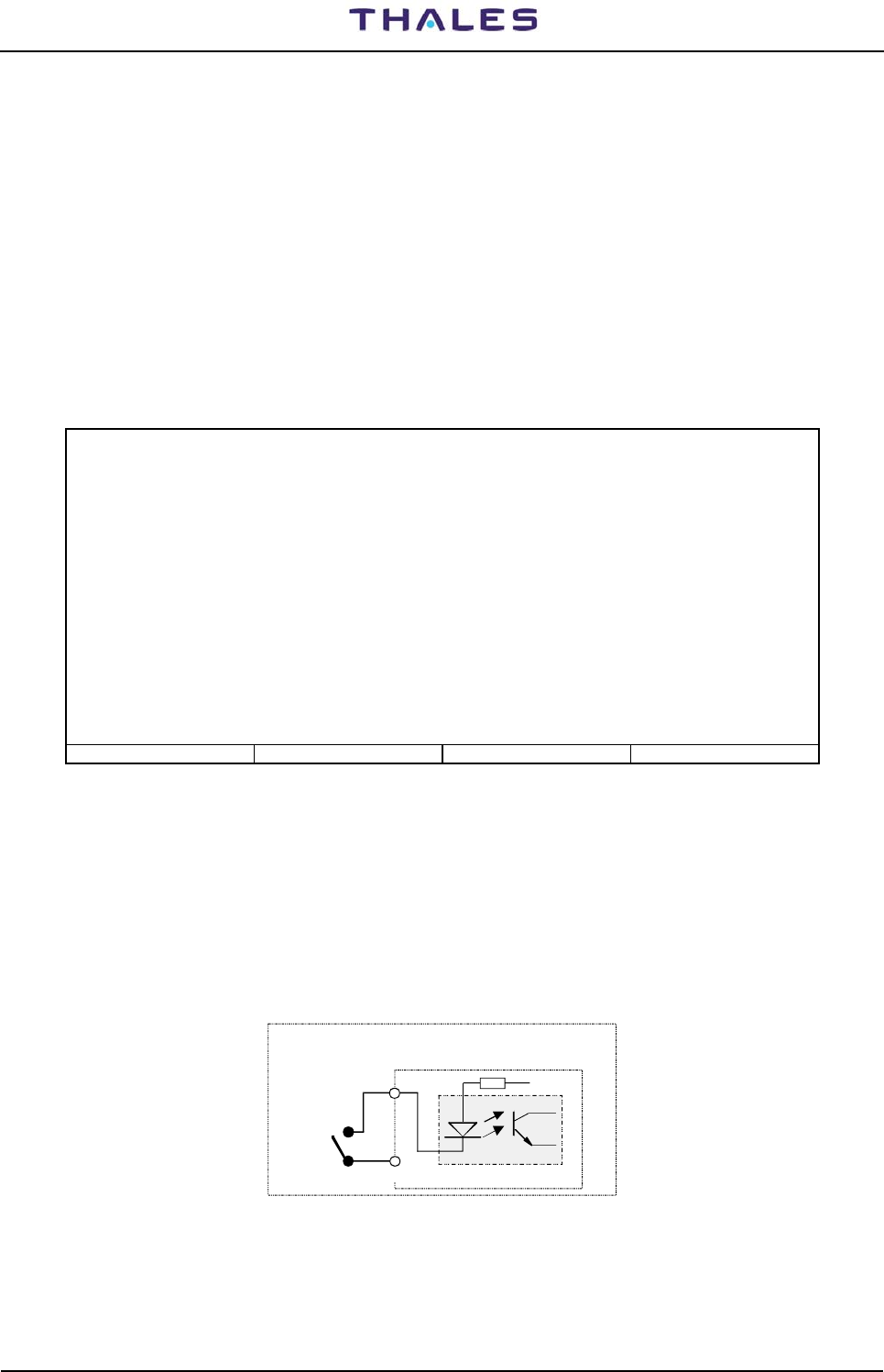
955 900 031 C DME 415/435 -Technical Manual
Vol. 1-Section 3 - Operation & Use
3-14 THALES Italia S.p.A.- A. S. D. Vers. D, September 2005
They come from outside and in general they define an Alarm condition. They use the AUX Input 0 to 7
ports.
− Internal Signals
They come from supply modules and define an alarm condition on a power supply module. They use
AUX input 8 to 15 and additional input IN 0 to 3 ports.
Both control panel keys and internal signals are wired in fixed way, but for more flexibility, they must be
configured in this screen.
For each line of the port must be set the following parameters:
− Enabling
This line is unused, it is possible to disable it.
− Functional mode, explained forward
When an input port is selected a page is displayed similar to that shown in figure 3.9 relating to the options
selection needed to configure the INC module on the front panel.
LCSU Maintenance Program Parallel input definition
Port: CONTROL INPUT
inp mode logic eqp_id control_id sharing_id type aux_descr
1 sElect Low 1
2 Cmdkey Low 1 1 Pnl.
3 Cmdkey Low 1 2 Pnl.
4 Cmdkey Low 1 0 Pnl.
5 Lamp Low
6 Buzzer Low 1
7 Disab
8 Disab
Press a key (<ESC>= abort, <+>= next, <->= previous, <ENTER>= modify):
F1 - Import Data F2 - Export Data F5 - Clear Video F10 - Quit
Figure 3.9. Parallel Input
For each line of the port must be set the following parameters:
Logic Active Low/High (fig 3.10)
This is the acquiring logic for the line. For control panel keys the logic is always "Low", for
internal signal is always "High"
In general, the configuration of the auxiliary input signal can be active "high or low". The
LCSU in "high way", sees alarm when the wire are not connected.
eqp_id: equipment identifier. To obtain it from "System Overview - equipment code"
Logic
: low = command closed (transistor Tr = ON)
high = command open (transistor Tr =OFF)
user
command
+Vcc
module CSB
Tr
(Gnd)
Figure 3.10. Input command Logic
control_id: an internal number from 0 to 15, ("CONTROL-ID"), used by the LCSU to communicate to
the Remote Users, in short way the signal changes
sharing_id: identifier of sharing, taken by the column of the control panel

DME 415/435 -Technical Manual
Vol. 1-Section 3 - Operation & Use 955 900 031 C
Vers. D, September 2005 THALES Italia S.p.A.- A. S. D. 3-15
type: indication of the signal type - PNL = panel (Inc), ext. = external commands, env = alarm of
environmental state of site
aux_descr: a string ("AUX-DESCR") of description, which is written on the history when the status
arrive signal changes
When a line is not used it is possible to disable with: "Disab"
The allowed function mode, are the following:
− Mode Auxiliary Input
The input is a signal carrying the status of an External Hardware line status port (smoke alarm,
temperature alarm, intrusion alarm, obstr. light …).
− Environment alarm LED lightning
The signal may be looked as an “Environment alarm". Therefore when, the signal goes in alarm
state, the corresponding LED on the Control Panel, light ON.
Figure 3.11 shows a significant example relating to the configuration for remote indications concerning the
beacon site ambient conditions and shows examples relating to indications used.
LCSU Maintenance Program Parallel input definition
Port: AUX INPUT 0..7
inp mode logic eqp_id control_id sharing_id type aux_descr
1 Auxil Low 0 LIGHT ON
2 Auxil Low 1 env DOOR
3 Disab
4 Disab
5 Disab
6 Disab
7 Disab
8 Disab
Line number: 1
Press a key (<ESC>= abort, <+>= next, <->= previous, <ENTER>= modify):
F1 - Import Data F2 - Export Data F5 - Clear Video F10 - Quit
Figure 3.11. Example of Beacon Site Environment
LCSU Maintenance Program Parallel input definition
Port: AUX INPUT 8..15
inp mode logic eqp_id control_id sharing_id type aux_descr
1 Paral High 1 10
2 Paral High 1 11
3 Paral High 1 4
4 Paral High 1 5
5 Paral High 1 8
6 Paral High 1 6
7 Paral High 1 9
8 Paral High 1 7
Press a key (<ESC>= abort, <+>= next, <->= previous, <ENTER>= modify):
F1 - Import Data F2 - Export Data F5 - Clear Video F10 - Quit
Figure 3.12.a. Aux input 8...15 - Configuration Examples

955 900 031 C DME 415/435 -Technical Manual
Vol. 1-Section 3 - Operation & Use
3-16 THALES Italia S.p.A.- A. S. D. Vers. D, September 2005
LCSU Maintenance Program Parallel input definition
Port: ADDITIONAL INPUT 0..3
inp mode logic eqp_id control_id sharing_id type aux_descr
1 Paral Low 1 0
2 Paral Low 1 1
3 Paral Low 1 2
4 Paral Low 1 3
5 Disab
6 Disab
7 Disab
8 Disab
Press a key (<ESC>= abort, <+>= next, <->= previous, <ENTER>= modify):
F1 - Import Data F2 - Export Data F5 - Clear Video F10 - Quit
Figure 3.12.b. Additional input 0.. 3 - Configuration Examples
In general, the auxiliary input configurations are to active high signal. In such way, the LCSU looks the
signal in alarm when the wire is not connected to.
− Command
The input is coming from the keys on the Control Panel or from an external panel.
To the signal are associated:
• An Internal Number, defining the pressed key
0=Request/Release
1=Equipment ON/OFF
2=Changeover
• The equipment identifier
This number must be kept from System Overview screen. For DME 415/435 is always =1
− Lamp test
This function define where is the Lamp Test key of the Control Panel.
No other information are required as the other keys on the Control Panel.
− Buzzer Silent
This function define how the silent key must be managed.
The only information needed is the referred equipment identifier to link to the silent key to the DME,
therefore the identifier, as explained before for the Commands, will be=1.
− Selection
This function defines the management of the "Select key" which allows the operator to enable the
"Detailed" section on the Control Panel.
The only information needed is the "Sharing Identifier" defining the equipment to show in the
"Detailed" section. In this case the Identifier is given by the column on the Control Panel when is the
Selection key. In the DME this Identifier is always =1
− Parallel internal Input
This function define the management of 12 Input Signals inside the DME cabinet carrying
information about mains and battery modules.

DME 415/435 -Technical Manual
Vol. 1-Section 3 - Operation & Use 955 900 031 C
Vers. D, September 2005 THALES Italia S.p.A.- A. S. D. 3-17
Are needed two information:
1) The equipment identifier. Obviously this is the DME and the value is always =1
2) The input identifier, which must be chosen from following table:
Table 3-5. List of the input Identifier
IDENTIFIER MEANING
0 +48V dc output AC/DC module 1 fail
1 +48V dc output AC/DC module 2 fail
2 +48V dc output AC/DC module 3 fail
3 +48V dc output AC/DC module 4 fail
4 Mains AC in AC/DC module 1 fail
5 Mains AC in AC/DC module 2 fail
6 Mains AC in AC/DC module 3 fail
7 Mains AC in AC/DC module 4 fail
8 Battery disconnected
9 Battery pre depletion
10 + 5vdc PWS module Subrack 1 fail
11 + 5vdc PWS module Subrack 2 fail
Figure 3.12 shows a significant example relating to the configuration concerning the Aux input.

955 900 031 C DME 415/435 -Technical Manual
Vol. 1-Section 3 - Operation & Use
3-18 THALES Italia S.p.A.- A. S. D. Vers. D, September 2005
3.2.2.3.4 Parallel Output Definition
Selecting option [4] in the “Configuration” menu the page is displayed showing the ports and parallel output
lines (figure 3.13) for the definition of the control logic.
The ports and output lines listed in figure 3.13 are relevant to:
− [0], [1], [2], [3] OUTPUT 1, 2, 3, 4 = INC module indications
− [4], [5] AUX OUTPUT 1, 2 = AUX 0..15 outputs
− [6] ADDITIONAL OUTPUT 0..4
− [7] BUZZER = Buzzer activation
LCSU Maintenance Program Parallel output definition
[n] port name
[0] OUTPUT 0
[1] OUTPUT 1
[2] OUTPUT 2
[3] OUTPUT 3
[4] AUX OUTPUT 0..7
[5] AUX OUTPUT 8..15
[6] ADDITIONAL OUTPUT 0..4
[7] BUZZER
Port:
F1 - Import Data F2 - Export Data F5 - Clear Video F10 - Quit
Figure 3.13. Parallel Output Definition
When a port or an output line is selected, a page is displayed similar to that shown in figures 3.15 relating to
the options selection [0,1,2,3] needed to configure the INC module on the front panel, and figure 3.16 to
configure the BUZZER.
The goal of this screen is to allow the customer to define how manage the digital output signals.
They are different kinds of signals
− Control Panel Indications
"Detailed indication", Main Status Indication, "LCSU" Indications, "Station" Indication, Buzzer.
They use the ports output 0,1,2,3 and Buzzer
− Auxiliary Output Signals
They carry out to outside some internal status of interest for the customer.
They use the AUX output 0 to 7, AUX output 8 to 15 and Additional output 0 to 4 ports.
− Parallel Internal Output AUX 0 to 4
Not provided
The Control Panel indications are wired in fixed way, but for more flexibility, they must be configured too.
For each line of the port must be set the following parameters:
- Out - group of output lines
- mode - Functional mode description
- logic: Active Low/High Level (see figures 3.14 and 3.15). It defines how change the status of the
signal. The indication of the control panel acquires a "Low" state to light ON.
- eqp_id: This function will carry out a status bit of an equipment , generally to light ON an indication
- status_id: This function will light ON an indication of the "Detailed " status section.
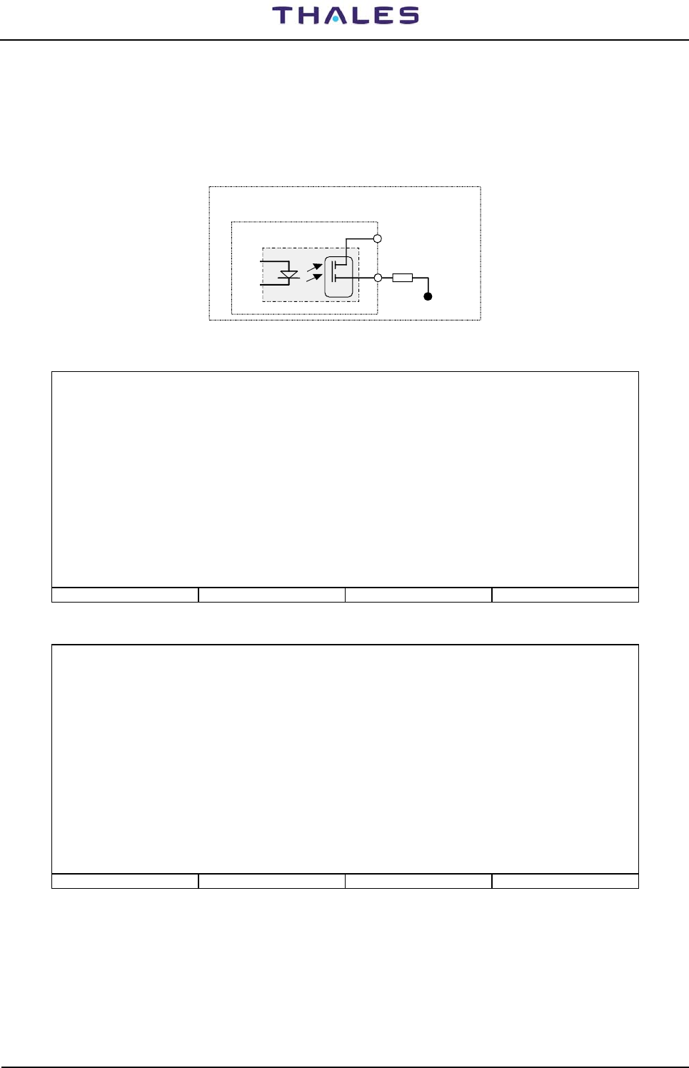
DME 415/435 -Technical Manual
Vol. 1-Section 3 - Operation & Use 955 900 031 C
Vers. D, September 2005 THALES Italia S.p.A.- A. S. D. 3-19
- sharing_id: This function will light ON the select Indication (green arrow on the select key)
- type: signal type - pnl = panel (INC); ext. = external commands; (LEV) or (PLS)
- aux_descr: string of parameter description. A description of the moved signal (this description will be
recorded in the history database)
- "Disab" - When a line is not used
Logic : low = FET open (>5M Ω)
high = FET condutting (50
Ω max)
user out load
V retourn
(Gnd)
Vdc or Vac
moduleCSB
0ptocoupl
FET
Figure 3.14. Output command Logic
LCSU Maintenance Program Parallel output definition
Port: OUTPUT 0
out mode logic eqp_id status_id sharing_id type aux_descr
1 State Low 0 2
2 Detail Low 21
3 Detail Low 18
4 State Low 0 0
5 Disab
6 Detail Low 15
7 Detail Low 17
8 sElect Low 1
Press a key (<ESC>= abort, <+>= next, <->= previous, <ENTER>= modify):
F1 - Import Data F2 - Export Data F5 - Clear Video F10 - Quit
Figure 3.15.a. Parallel Output Definition - OUT 0
LCSU Maintenance Program Parallel output definition
Port: OUTPUT 1
out mode logic eqp_id status_id sharing_id type aux_descr
1 Disab
2 Detail Low 11
3 Detail Low 7
4 Detail Low 6
5 Detail Low 9
6 Detail Low 12
7 Detail Low 13
8 Detail Low 19
Press a key (<ESC>= abort, <+>= next, <->= previous, <ENTER>= modify):
F1 - Import Data F2 - Export Data F5 - Clear Video F10 - Quit
Figure 3.15.b. Parallel Output Definition - OUT 1

955 900 031 C DME 415/435 -Technical Manual
Vol. 1-Section 3 - Operation & Use
3-20 THALES Italia S.p.A.- A. S. D. Vers. D, September 2005
LCSU Maintenance Program Parallel output definition
Port: OUTPUT 2
out mode logic eqp_id status_id sharing_id type aux_descr
1 Detail Low 10
2 Detail Low 5
3 Detail Low 3
4 Detail Low 4
5 Detail Low 8
6 Detail Low 0
7 Detail Low 1
8 Detail Low 2
Press a key (<ESC>= abort, <+>= next, <->= previous, <ENTER>= modify):
F1 - Import Data F2 - Export Data F5 - Clear Video F10 - Quit
Figure 3.15.c. Parallel Output Definition - OUT 2
LCSU Maintenance Program Parallel output definition
Port: OUTPUT 3
out mode logic eqp_id status_id sharing_id type aux_descr
1 State Low 1 12
2 State Low 1 2
3 State Low 1 3
4 State Low 1 0
5 Disab
6 Disab
7 Disab
8 Detail Low 14
Press a key (<ESC>= abort, <+>= next, <->= previous, <ENTER>= modify):
F1 - Import Data F2 - Export Data F5 - Clear Video F10 - Quit
Figure 3.15.d. Parallel Output Definition - OUT 3
LCSU Maintenance Program Parallel output definition
Port: AUX OUTPUT 0…7
out mode logic eqp_id status_id sharing_id type aux_descr
1 Auxil High 0 pls LIGHT OFF
2 Auxil High 1 Lev COOLER
3 Disab
4 Disab
5 Disab
6 Disab
7 Disab
8 Disab
Press a key (<ESC>= abort, <+>= next, <->= previous, <ENTER>= modify):
F1 - Import Data F2 - Export Data F5 - Clear Video F10 - Quit
Figure 3.15.e. Parallel Output Definition - AUX OUTPUT O..7

DME 415/435 -Technical Manual
Vol. 1-Section 3 - Operation & Use 955 900 031 C
Vers. D, September 2005 THALES Italia S.p.A.- A. S. D. 3-21
LCSU Maintenance Program Parallel output definition
Port: BUZZER
out mode logic eqp_id status_id sharing_id type aux_descr
1 Buzzer Low 1
2 Disab
3 Disab
4 Disab
5 Disab
6 Disab
7 Disab
8 Disab
Press a key (<ESC>= abort, <+>= next, <->= previous, <ENTER>= modify):
F1 - Import Data F2 - Export Data F5 - Clear Video F10 - Quit
Figure 3.16. Parallel Output Definition - Buzzer
The allowed function "mode" are the following:
• Auxiliary output
This function carries out an internal state of an equipment. It needs of the following parameters:
- A description of the moved signal (this description will be recorded in the history database)
- An Internal Number (from 0 to 15) used by the LCSU to communicate to the remote user the
change made. The internal state is the status bit of the equipment 0 (/LCSU), computed as this
number + 32.
- The kind of change to do
Pulse (PLS): the LCSU will force the signal in active state for 0,5 second and then returns to in
active states,
− Level (LEV): the signal will follow the conditions of the related internal state.
− Equipment Status ("eqp_id")
This function will carry out a status bit of an equipment , generally to light ON an indication, and
requires the following information:
• The involved equipment
0=LCSU ; 1=DME
• The status bit ("Status _Id")
A number kept from the table 3-7 (for DME) or 3-8 (for LCSU) in the column "Spec. Number".
This function is used in "Main Status" or "LCSU" sections of the Control Panel and for other
external control Panels.
− Selection ("sharing_id")
This function will light ON the select Indication (green arrow on the select key) when the detailed
section is enabled. It requires only the "Sharing Identifier", computed as the same parameter of
selection key (parallel input).
Therefore will be=1 always.
− Buzzer ("eqp_id")
This function defines how enable the buzzer. It receives only the "Equipment Identifier" of the
involved equipment. This parameter is always =1.
− Detailed Status ("Status_id")
This function will light ON an indication of the "Detailed " status section. It requires only the Detailed
Indication to change.
This information may be found in the following table 3-6 (column IND):

955 900 031 C DME 415/435 -Technical Manual
Vol. 1-Section 3 - Operation & Use
3-22 THALES Italia S.p.A.- A. S. D. Vers. D, September 2005
Table 3-6. List of the Detailed Status Indications
IND DESCRIPTION IND DESCRIPTION
0 Monitor 1 Alarm 1 Monitor 2 Alarm
2 Monitor 1 StbyAlarm 3 Monitor 2 StbyAlarm
4 Monitor 1 Faulty 5 Monitor 2 Faulty
6 Monitor 1 Bypassed 7 Monitor 2 Bypassed
8 TRX1 ON 9 TRX2 ON
10 TRX1 Warning 11 TRX2 Warning
12 TRX1 Faulty 13 TRX2 Faulty
14 TRX1 on Antenna 15 TRX2 on Antenna
16 Control Engaged 17 Control Enabled
18 Mains OFF 19 Environment alarm
20 Antenna faulty 21 Other Warning
The linking of the Detailed Indication with the Status Bit of the equipment is made in the "LCSU Site
Equipment" status list table 3-7.

DME 415/435 -Technical Manual
Vol. 1-Section 3 - Operation & Use 955 900 031 C
Vers. D, September 2005 THALES Italia S.p.A.- A. S. D. 3-23
Table 3-7. List of Equipment Status
Spec.
Number STATUS Front panel “INC”
Indications Spec.
Number STATUS Front panel “INC”
Indications
0 DATA COMM faulty MAIN STATUS 40 Trx2 operating TX2 ON
1 NORMAL MAIN STATUS 41 Trx2 ok
2 WARNING MAIN STATUS 42 Trx2 shutdown TX2 FAULTY
3 ALARM MAIN STATUS 43 Trx2 degraded
4 Maintenance 44 Reserved
5 Reserved 45 Reserved
6 Reserved 46 Reserved
7 Beacon under user control MAIN STATUS 47 Reserved
8 Beacon off 48 Monitor 1 faulty MON1 FAULTY
9 Beacon qual ok 49 Monitor 2 faulty MON2 FAULTY
10 Beacon qual. Degraded 50 Reserved
11 Beacon qual faulty 51 Reserved
12 Beacon operating 52 Communication faulty with Monitor 1
13 Alarm 53 Communication faulty with Monitor 2
14 Warning 54 Communication faulty with TRX 1
15 Reduced power 55 Communication faulty with TRX 2
16 reserved 56 OR of equipment communic. faulty
17 Reserved 57 Beacon restart active
18 Power from Battery MAINS OFF 58 TRX 1 Warning
19 Trx standby faulty 59 TRX 2 Warning
20 Trx1 on antenna TX1 ON ANT 60 Single Monitor
21 Trx2 on antenna TX2 ON ANT 61 Single Transponder
22 Automatic Routine Check 62 One monitor faulty
23 Equipment in default parameter 63 Reserved
24 Monitor alarm disagreement 64 Trx 2 standby ok
25 Change over 65 Trx standby degraded
26 Manual control 66 Mon1 qual. Trx on ant. OK
27 Other Warning OTHER WARN 67 Mon1 qual. Trx on ant. degraded
28 Trx 1 off 68 Mon1 qual. Trx on antenna faulty
29 Trx1 standby 69 Mon1 qual. Trx stby OK
30 Trx1 on 70 Mon1 qual. Trx stby degraded
31 Trx1 operating TX1 ON 71 Mon1 qual. Trx stby faulty MON1 STBALRM
32 Trx1 ok 72 Mon2 qual. Trx on ant. OK
33 Trx1 shutdown 73 Mon2 qual. Trx on ant. degraded
34 Trx1 degraded 74 Mon2 qual. Trx on ant. faulty
35 Reserved 75 Mon2 qual. Trx stby OK
36 Trx 1 F.A. faulty 76 Mon2 qual. Trx stby degraded
37 Trx 2 off 77 Mon2 qual. Trx stby faulty MON2 STBALRM
38 Trx2 standby 78 Monitor 1 bypass MON1
BYPASSED
39 Trx2 on 79 Monitor 2 bypass MON2
BYPASSED
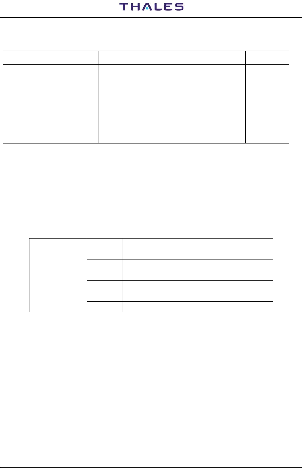
955 900 031 C DME 415/435 -Technical Manual
Vol. 1-Section 3 - Operation & Use
3-24 THALES Italia S.p.A.- A. S. D. Vers. D, September 2005
Table 3-8. List of the Indications from LCSU to User
Spec.
Number STATUS “INC”
Indications Spec.
Number STATUS “INC”
Indications
0 DATA COM 9 ( ) Clock calendar faulty
1 NORMAL 10 ( ) History faulty
2 (*) WARNING (*) LCSU WARNING 11 ( ) Clock calendar warning
3 ALARM 12 ( ) Environmental Alarm ENV ALRM
4 MAINTENANCE 13 ( ) Frozen state
5 - 14,15 -
6 - 16..31 Auxiliary input 0...15
7( ) LCSU under user control 32..47 Auxiliary output 0...15
8 ( ) Battery faulty Watch Dog ( Hardware) LCSU
OPERATION
(*) Warning = "OR" of the Specification Number "8 ( ) to 13 ( )"
3.2.2.3.5 Commands equipments list
In this paragraph are listed the available controls to command the different equipment.
They can be assigned to parallel on/off inputs, coming from the control panel or external devices.
To configure the inputs, enter the number corresponding to the desired command required.
Table 3-9. Equipment Commands list
EQUIPMENT NUMBER DESCRIPTION
0 take/release the control
1 beacon on/off
2 changeover
3 beacon off (No valid on DME 415/435)
4 tx 1 main (No valid on DME 415/435)
DME AN 415/435
DME FSD 40/45
5 tx 2 main (No valid on DME 415/435)

DME 415/435 -Technical Manual
Vol. 1-Section 3 - Operation & Use 955 900 031 C
Vers. D, September 2005 THALES Italia S.p.A.- A. S. D. 3-25
3.2.2.3.6 User Connection Parameters
Select option [5] on the “Configuration” menu to display the page shown in figure 3.17 that enables
modification of some modem connection parameters.
LCSU User connection parameters
Leased line parameters
[0] Connection attempt duration: 60 sec. (20 - 120)
Switched line parameters
[1] Connection speed: 3 (1: 300 , 2: 1200, 3: 2400,
4: 4800, 5: 9600)
[2] Dial attempt duration: 90 sec (20 - 120).
[3] 2nd call delay: 2 min.
[4] 3rd call delay: 5 min.
[5] 4th call delay: 10 min.
[6] Subsequent calls delay: 0 min. (0: disabled)
[7] Full connect. idle timeout: 0 min. (0: disabled)
[8] Delay before call-back: 10 sec.
[9] Call back 0 (0:disable 1:enable)
Party line parameters
[10] Preliminary waiting time: 0 sec (1 - 5000, 0:disable)
[11] Post waiting time: 0 sec (1 - 5000, 0:disable) Up to march 05
[12] Intermediate waiting time: 0 sec (1 - 5000, 0:disable)
Select:
F1 - Import Data F2 - Export Data F5 - Clear Video F10 - Quit
Figure 3.17. User Connection Parameters
Below the meanings of each parameter that can be modified are given:
- Connection attempt duration
time interval within which the connection in dedicated line should take place.
- Connection speed
Baud rate of the connection between LCSU and Modem
- Dial attempt duration
time interval within which the connection in switched line should take place
- 2nd call delay
time to wait before retry the second call in case of dial connection not made. – 0 means no retry
- 3rd call delay
time to wait before retry the 3rd call in case of dial connection not made. – 0 means no retry
- 4th call delay
time to wait before retry the 4th call in case of dial connection not made. – 0 means no retry
- Subsequent calls delay
delay time for subsequent calls - 0 (disabled): the user is not called again after an unsuccessful attempt.
- Full connect. idle timeout
maximum connection time allowed in full without exchange of messages.
- Delay before call-back
Delay between end of call and call-back.
- Call back
Call-back enable. When called, the LCSU recall the User in order to authorize it to send the commands, if
enabled for this operation.
Party-line parameters: waiting times of communication
- Preliminary waiting time: 0 msec (1 - 5000, 0: disable)
- Post waiting time: 0 msec (1 - 5000, 0: disable) Up to march 05
- Intermediate waiting time: 0 msec (1 - 5000, 0: disable)

955 900 031 C DME 415/435 -Technical Manual
Vol. 1-Section 3 - Operation & Use
3-26 THALES Italia S.p.A.- A. S. D. Vers. D, September 2005
3.2.2.3.7 LCSU Site Equipment Configuration
This screen option [6] (figure 3.18) allow the customer to link the outputs mapped as "Detailed" in the
"Parallel Output Definition" to the Equipment Status (see table 3-7) - List of Equipment Status –
The elements have the following effect:
Description: description of the equipment to be represented
Manuf: Producer: 0 = LCSU System, 1 = Thales (ANS)
Eqp code equipment code: 0 = LCSU, 1 = DME/N, 2 = DME/P, 3 = NDB 436
Position in Main Status LCSU = Disab; 1 = equipment on which LCSU is assembled
Select: 1 = line configuration; 2 = detailed status configuration
Inserting selection 2 "Detailed status configuration" is shown the fig. 3.19
First must be set the "position in Main Status", that indicates the position on the Control Panel, where is
shown the equipment status. For the DME this position is always =0
The next sub-screen (figure 3.19) allows, doing the linking said before.
Each selection is referred to an indication on the control Panel (in the Detailed Status section). The value to
set must be kept in the table 3-7.
A value=1 disable the indication. For instance, the DME doesn't have the status of the antenna, then the
indication [20] (Antenna faulty) must be disabled.
The indication [16] (control Engaged), [17] (control Enabled) and [19] (Environment Alarm) don't have any
reference to the equipment status; therefore a value different than the 1 (disable) is shown as enabled.
The indication [22] (Mains status label) allow the operator to define the label to set in the display on the main
status
LCSU Maintenance Program LCSU site equipment configuration
[n] Description Manuf Equip. Code Position in Main status
[0] LCSU unit 0 0 Dis
[1] ANS-DMEN 415/435 1 1 1
Select:
1: Line configuration 2: Detailed Status Configuration
F1 - Import Data F2 - Export Data F5 - Clear Video F10 - Quit
Figure 3.18. LCSU Site equipment menu
LCSU Maintenance Program LCSU site equipment configuration
Equipment: 1 Position in Main status: 1
[0] Monitor 1 Alarm :68 [1] Monitor 2 Alarm :74
[2] Monitor 1 Stand-by Alarm :71 [3] Monitor 2 Stand-by Alarm :77
[4] Monitor 1 Faulty :48 [5] Monitor 2 Faulty :49
[6] Monitor 1 Bypassed :78 [7] Monitor 2 Bypassed :79
[8] Trx 1 On :31 [9] Trx 2 On :40
[10] Trx 1 Warning :58 [11] Trx 2 Warning :59
[12] Trx 1 Faulty :33 [13] Trx 2 Faulty :42
[14] Trx 1 On Antenna :20 [15] Trx 2 On Antenna :21
[16] Control engaged :Ena [17] Control engaged :Ena
[18] Mains off :18 [19] Environment alarm :Ena
[20] Antenna faulty :Dis [21] Other warning :27
[22] Main status label: THAL
Select the item to change (0 to 22):
F1 - Import Data F2 - Export Data F5 - Clear Video F10 - Quit
Figure 3.19. Status of LCSU Site equipment

DME 415/435 -Technical Manual
Vol. 1-Section 3 - Operation & Use 955 900 031 C
Vers. D, September 2005 THALES Italia S.p.A.- A. S. D. 3-27
3.2.2.3.8 LCSU Site Parameter
This screen option [7] (figure 3.20) allow the operator to change some information about the site:
[0] Number of changing before status freezing:
This parameters allows the operator to stop the recording of some auxiliary input that changes is
value too fast. This option prevent the history database is filled with a lot of unused records.
[1] Control superside
It defines how the LCSU must manage the Control Request coming from outside or from the control
Panel when another user is controlling the equipment.
Three choice are allowed:
1) Disable: a new Control Request is refused, an user that has the equipment control cannot be
interrupted by another user
2) Enable: it is the opposite of the previous item, any user may keep the equipment control,
interrupting any other user.
3) On Priority: this is the classic way to manage the Request. The control Request is accepted
only if the requestor has an higher priority than the present owner.
The Local Control Panel has the highest priority, than follows the local PC and the Remote
Control RCSI. The priority is computed as the number of intermediate nodes between the user
and equipment.
LCSU Maintenance Program LCSU site parameter
[0] Number of changing before status freezing: 0 (1-100, 0:disabled) Dis
[1] Control superside: 1 (0:dis, 1:on prior, 2:Ena)
Select:
F1 - Import Data F2 - Export Data F5 - Clear Video F10 - Quit
Figure 3.20. LCSU Site parameter
3.2.2.3.9 REU parameters
Selecting option [8] in the “Configuration” menu the page of figure 3.21 is displayed. This screen enables the
change to the parameters of the REU (When equipment is in station system with Remote Equipment Unit on
RCSE unit, otherwise the values won't be considered).
LCSU Maintenance Program Reu parameters
[0] Lke Equipment address: 160 (0..4095)
[1] Lke Reu address: 16 (0..4095)
[2] Modem identifier: MODEM 001
Select:
F1 - Import Data F2 - Export Data F5 - Clear Video F10 - Quit
Figure 3.21. Reu Parameters
This table must be compiles in a system of connection in telephone switched line with remote control type
REU - Otherwise the values won't be considered.
- In the option [0] some first line must be inserts the identifier of the LCSU: value to be deduced from the
manual of the remote control REU to which is postponed
- In the option [1] must be inserts the identifier of the remote control REU: value to be deduced from the
manual of the remote control REU to which is postponed
- In the option [2] must be inserts always the string "Modem 001"
Identifiers of LCSU and of REU must have carry over in the file *. ptt to be loaded in the program of REU
necessarily called "LLKE".

955 900 031 C DME 415/435 -Technical Manual
Vol. 1-Section 3 - Operation & Use
3-28 THALES Italia S.p.A.- A. S. D. Vers. D, September 2005
3.2.2.3.10 Export Configuration Data
Select the option [9] on the menu “Configuration” to show on the display (fig. 3.22) the page with the
procedure of export of the configuration data with the information: LCSU ready to send configuration dates
to the PC. Press key F1 to transfer the configuration data from the LCSU to PC after entering the indication
requested relevant to the name of the file where the data is to be stored.
LCSU Maintenance Program Export LCSU configuration data
LCSU ready to send configuration data to the PC
Start the operation by pressing <F1> key.
F1 - Import Data F2 - Export Data F5 - Clear Video F10 - Quit
Figure 3.22. Export LCSU configuration data
3.2.2.3.11 Import Configuration Data
To select the option [10] on the menu “Configuration” to show on the display (fig. 3.23), the page with the
procedure of import of the configuration data with the information: LCSU ready to get configuration dates
from the PC. Press key F2 to start the configuration data loading from PC to LCSU.
LCSU Maintenance Program Import LCSU configuration data
LCSU ready to get configuration data from the PC
Start the operation by pressing <F2> key.
F1 - Import Data F2 - Export Data F5 - Clear Video F10 - Quit
Figure 3.23. Import LCSU configuration data
3.2.2.3.12 Hardware Test
Select option [3] from the Main menu to display the page shown in figure 3.24 containing the options relating
to functionality verification of the input and output ports and the control emulating the serial lines.
LCSU Maintenance Program Hardware Test
[1] Test of parallel input port
[2] Test of parallel output port
[3] Test of serial lines
[0] Return
Select: []
F1 - Import Data F2 - Export Data F5 - Clear Video F10 - Quit
Figure 3.24. Hardware Test

DME 415/435 -Technical Manual
Vol. 1-Section 3 - Operation & Use 955 900 031 C
Vers. D, September 2005 THALES Italia S.p.A.- A. S. D. 3-29
3.2.2.3.13 Test of Parallel Input Port
Select option [1] on the “Hardware Test” menu to display the page shown in figure 3.25 that is used to test
the input ports.
LCSU Maintenance Program Test of parallel input port
[n] port name
[0] CONTROL INPUT
[1] AUX INPUT 0..7
[2] AUX INPUT 8..15
[3] ADDITIONAL INPUT 0..3
Select:
F1 - Import Data F2 - Export Data F5 - Clear Video F10 - Quit
Figure 3.25. Test of Parallel Input Port
Some examples of tests that can be made to verify the inputs listed below are shown in the figures that
follow:
CONTROL INPUT (figure 3.26)
The test is performed through the push-buttons on the INC module, which can be found according to the
configured arrangement using the procedure described in paragraph 3.2.2.3.3
AUX INPUT (figure 3.27)
the test is performed by creating a closure to the common pin, through the pins on connector PL3 of the I/O
panel. These can be found according to the configured arrangement using the procedure described in
paragraph 3.2.2.3.3.
ADDITIONAL INPUT (figure 3.28)
the test is performed by creating a closure to the common pin, through the pins on connector PL3 of the I/O
panel. These can be found according to the configured arrangement using the procedure described in
paragraph 3.2.2.3.3.
Port: CONTROL INPUT - Current read line status:
1->LOW 2->LOW 3->LOW 4->LOW 5->LOW 6->LOW 7->LOW 8->LOW
Press a key to start status monitor or <ESC> to exit.
** Monitor on input line active **
Changed line number 2 LOW ==> HIGH
Changed line number 2 HIGH ==> LOW
F1 - Import Data F2 - Export Data F5 - Clear Video F10 - Quit
Figure 3.26. Test Control Input

955 900 031 C DME 415/435 -Technical Manual
Vol. 1-Section 3 - Operation & Use
3-30 THALES Italia S.p.A.- A. S. D. Vers. D, September 2005
Port: AUX INPUT 0..7 - Current read line status:
1->HIGH 2-> HIGH 3-> HIGH 4-> HIGH 5-> HIGH 6-> HIGH 7-> HIGH 8-> HIGH
Press a key to start status monitor or <ESC> to exit.
** Monitor on input line active **
Changed line number 8 HIGH ==> LOW
Changed line number 8 LOW ==> HIGH
F1 - Import Data F2 - Export Data F5 - Clear Video F10 - Quit
Figure 3.27. Test Aux Input
Test Aux Input
Port: ADDITIONAL INPUT - Current read line status:
1->HIGH 2->HIGH 3->HIGH 4->HIGH 5->HIGH 6->HIGH 7->LOW 8->HIGH
Press a key to start status monitor or <ESC> to exit.
** Monitor on input line active **
F1 - Import Data F2 - Export Data F5 - Clear Video F10 - Quit
Figure 3.28. Test Additional Input
3.2.2.3.14 Test of Parallel Output Port
Select option [2] on the “Hardware Test” menu to display the page shown in figure 3.29 that is used to test
the parallel output ports.
LCSU Maintenance Program Test of parallel output port
[n] port name
[0] OUTPUT 0
[1] OUTPUT 1
[2] OUTPUT 2
[3] OUTPUT 3
[4] AUX OUTPUT 0..7
[5] AUX OUTPUT 8..15
[6] ADDITIONAL OUTPUT 0..4
[7] BUZZER
Select:
F1 - Import Data F2 - Export Data F5 - Clear Video F10 - Quit
Figure 3.29. Test of Parallel Output Port

DME 415/435 -Technical Manual
Vol. 1-Section 3 - Operation & Use 955 900 031 C
Vers. D, September 2005 THALES Italia S.p.A.- A. S. D. 3-31
The operator can choose to test all eight lines of each port or only separate lines (A = all bits or n = line
number). LEDs on the INC module light up after the selection to indicate that the selected line is operating
correctly. The AUX OUTPUT lines have to be checked with an ohmmeter if they are not connected to
specific indicators.
Using <+> and <-> keys the operator may also check brightness of the LEDs on the Control Panel. The
brightness is arranged in 7 levels, shown in the column Bright.
This procedure is meaning only if the port under test is referring to the Control Panel
The figures below show some examples of tests to check the following outputs:
OUTPUT 0,1, 2, 3 (figure 3.30)
use the keyboard to select the line to be tested and check output variation.
AUX OUTPUT (figure 3.31)
use the keyboard to select the line to be tested and check output variation.
BUZZER (figure 3.32)
Port: OUTPUT 1 - All lines initialized to ACTIVE status:
Select line to change (A = all bits; 1-8 = line number; <+>, <->= brightness) or <ESC> to exit.
1->LOW 2->HIGH 3->LOW 4->LOW 5->LOW 6->LOW 7->LOW 8->LOW BRIGHT=3
1->LOW 2->LOW 3->LOW 4->LOW 5->LOW 6->LOW 7->LOW 8->LOW BRIGHT=3
1->LOW 2->HIGH 3->LOW 4->LOW 5->LOW 6->LOW 7->LOW 8->LOW BRIGHT=3
1->HIGH 2->LOW 3->HIGH 4->HIGH 5->HIGH 6->HIGH 7->HIGH 8->HIGH BRIGHT=3
F1 - Import Data F2 - Export Data F5 - Clear Video F10 - Quit
Figure 3.30. Test Output port 1
Port: AUX OUTPUT - All lines initialized to ACTIVE status:
Select line to change (A = all bits; 1-8 = line number; <+>, <->= brightness) or <ESC> to exit
1->HIGH 2->HIGH 3->HIGH 4->HIGH 5->HIGH 6->HIGH 7->HIGH 8->HIGH BRIGHT=3
1->LOW 2->LOW 3->LOW 4->LOW 5->LOW 6->LOW 7->LOW 8->LOW BRIGHT=3
1->HIGH 2->HIGH 3->HIGH 4->HIGH 5->HIGH 6->HIGH 7->HIGH 8->HIGH BRIGHT=3
1->HIGH 2->LOW 3->HIGH 4->LOW 5->HIGH 6->HIGH 7->HIGH 8->HIGH BRIGHT=3
F1 - Import Data F2 - Export Data F5 - Clear Video F10 - Quit
Figure 3.31. Test Aux Output

955 900 031 C DME 415/435 -Technical Manual
Vol. 1-Section 3 - Operation & Use
3-32 THALES Italia S.p.A.- A. S. D. Vers. D, September 2005
Port: BUZZER - All lines initialized to ACTIVE (LOW) status:
Select line to change (A = all bits; 1-8 = line number; <+>, <->= brightness) or <ESC> to exit
1->HIGH 2->HIGH 3->HIGH 4->HIGH 5->HIGH 6->HIGH 7->HIGH 8->HIGH
1->LOW 2->HIGH 3->HIGH 4->HIGH 5->HIGH 6->HIGH 7->HIGH 8->HIGH
1->HIGH 2->HIGH 3->HIGH 4->HIGH 5->HIGH 6->HIGH 7->HIGH 8->HIGH
F1 - Import Data F2 - Export Data F5 - Clear Video F10 - Quit
Figure 3.32. Test Buzzer
3.2.2.3.15 Test of Serial Lines
Select option [3] on the “Hardware Test” menu to display the page shown in figure 3.33 that is used to
perform the tests on serial lines.
LCSU Maintenance Program Test of serial lines
Serial port number to test (1 to 6):
F1 - Import Data F2 - Export Data F5 - Clear Video F10 - Quit
Figure 3.33. Test of Serial Lines
When the number of the port to be tested is selected, a page is displayed similar to that shown in figure
3.34, that indicates an example of a test on port number 2, for which a modem connection is necessary.
Testing port number: 2
Press a key to start emulation or <ESC> to abort
** Emulation program active <ESC>Exit <CTRL-D>Test DTR/DCD Loop **
F1 - Import Data F2 - Export Data F5 - Clear Video F10 - Quit
Figure 3.34. Testing of Port Number
NOTES
− The serial port diagnostics are performed when module CSB on the LCSU is
powered on;

DME 415/435 -Technical Manual
Vol. 1-Section 3 - Operation & Use 955 900 031 C
Vers. D, September 2005 THALES Italia S.p.A.- A. S. D. 3-33
− The request to test port 1 is followed by a message “The emulation port is not
testable. Press a key to continue...” since this is the connection port to the PC
that the operator is using to dialogue;
− For DME equipment the modem 1 and 2 is usually connected to serial port 2
and 3 (PL2 and PL1 of I/O panel);
− The functional verification is performed by typing one or more alphanumeric
characters from the keyboard, the relevant echo is shown on the PC screen;
− The operator must respond to the request to define the baud rate of the
modem, if provided on the serial port to be tested:
1 = 300; 2 = 1200 ; 3 = 2400 ; 4 = 4800 ; 5 = 9600; 6 = 19200
− Upon the request message PARITY (N)one, E(ven), O(dd); “N” in other cases.
3.2.2.4 Test Data Consistency
To terminate the configuration procedure it is necessary to return to the “Configuration” page and select
option [0].
The program then asks the operator whether the configuration data modifications saving procedure is to be
performed. The following message will be displayed:
“Save configuration changes? (Y/N):”
If the reply is “Y” a test is run that can be seen in figure 3.35. If the result is positive, the last line will display
the message:
“Press a key to start saving.”
whereas if the result is negative the previous message is replaced by the indication of the fault found. (E.g.:
“E2PROM faulty, data not saved. Press any key to continue..”)
The saving operation is indicated by a row of asterisks that appear in sequential order at the end of the
operation.
Testing data consistency...
Testing site code... OK
Testing port connection... OK
Testing user identification codes... OK
Testing buzzer connection... OK
Testing control commands equipment connection... OK
Testing commands equipment connection... OK
Press a key to start saving.
F1 - Import Data F2 - Export Data F5 - Clear Video F10 - Quit
Figure 3.35. Test Data Consistency
3.2.2.5 To Exit from the Program
To exit from the configuration procedure, first return to the “MAIN MENU” and select option [0].
To close the “EMUL.exe” program, press F10 (quit.).
Do not forget to select the option [0] of the "Main Menu": the CSB does not leave the configuration program
if you press F10 key only.
CAUTION

955 900 031 C DME 415/435 -Technical Manual
Vol. 1-Section 3 - Operation & Use
3-34 THALES Italia S.p.A.- A. S. D. Vers. D, September 2005
3.2.2.6 Modem Configuration
When using a modem for connections to the different units at a distance from the site where the beacons
are installed, it has to be suitably configured for the specific service it is prepared for.
Modems used for the various connections have to operate:
− in the phonic band (300 - 3400 Hz);
− on 2-wire dedicated or switched lines;
− in accordance with CCITT V21, V22 and V22bis standards;
− with AT protocol controls;
− with asynchronous mode communication.
The modem configuration is prepared modifying its internal parameters through AT controls.
The configuration may be in two ways:
1. Connect a PC to the modem using a terminal emulation program; it is then possible to modify the
relevant parameters using a series of AT commands.
This type of operation requires detailed knowledge of the modem parameters.
2. Connect a PC to the modem and run the program typing in <modem mdfile.mdm>, then press the
ENTER key.
The modem.exe program imports the configuration data from the mdfile.mdm file and sends it, in
sequence, to the modem, verifying each time that it has been accepted correctly.
The UTIL - Configuration Utility diskette contains several examples of *.mdm files previously prepared for
some types of modem. The AT standard does not guarantee that all modems have the same commands,
therefore it is necessary to prepare the *.mdm files for each specific modem. These files can be edited by
the user, starting from one of the existing examples and using a normal text editor the desired parameters
can be modified to obtain the suitable file.
The main parameters to be configured in order to work correctly with LCSU are:
AT&L0(1) line type (dedicated or switched)
ATB0 CCITT full duplex standard
ATFn line speed (n defines the standard and depends on the modem used)
AT&C1 Interfaced criteria forced to work state
ATX0 Blind dial without busy or ready tone recognition
AT&D3 DTR transition ON -> OFF cause modem reset
AT&G0 Guard tone disabled
ATS10=40 Carrier faulty disconnect delay time 1/10 s
ATT(P) Tone/pulse dialing
ATS0=2 Number of rings (only in switched)
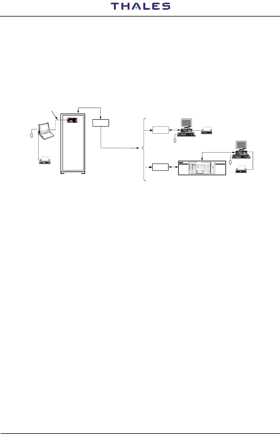
DME 415/435 -Technical Manual
Vol. 1-Section 3 - Operation & Use 955 900 031 C
Vers. D, September 2005 THALES Italia S.p.A.- A. S. D. 3-35
3.2.3 File Configuration in Supervisory Program
A personal computer can be connected in the following way:
− LOCAL, directly through a serial port.
− REMOTE, through a modem on dedicated or switched lines.
Installation and procedure refer APPENDIX B –"PC User WINDOWS SUPERVISOR" section
Examples are in figure 3.36
RS-232
SERIAL LINE
"REMOTE" PC
TELEPHON LINE
RCSI
CONTROL
REMOTE
Internal
or External
MODEM
MODEM
"REMOTE" PC
PC
"LOCAL"
(laptop or
desktop type)
DME
RCSI 446
EQUIPMENT RCSI
12
DETAILED STAT USMAIN STATUS
COMMAND
MODEM
RS-232C -SERIAL LINE
switched or dedicated line
Mouse
Printer
Internal
or External
Mouse
Mouse
Printer
Printer
(e.g.COM1)
Figure 3.36. System control via PC (example)

955 900 031 C DME 415/435 -Technical Manual
Vol. 1-Section 3 - Operation & Use
3-36 THALES Italia S.p.A.- A. S. D. Vers. D, September 2005
3.3 INDICATORS ON THE MODULES
This paragraph shows the set of indicators on the various modules of the beacon. The LCSU front indicators
are described in table 3-1. The front outlines of the modules are gives on the figures 3.37, 3.38, 3.39 and
indicators of each module are described in table 3-10.
Table 3-10. LEDs Indicators on the Front of every modules
Module REF Lamp
color LABEL DESCRIPTION
Normal
condition
Red PWS Faulty Possible overload, overvoltage, overheat or module failure OFF
PWS
Green INPUT Correctly input voltage ON
RD4 Red WATCHDOG LED on when failure of Watchdog operation (Monitor CPU: stop condition) OFF
RD5 Yellow Morse Code The led ON during the decoded and self check of identity frequency (1350
Hz)
RD3 Yellow TRX ALARM The LED ON, when secondary and primary alarm of transponder in
antenna occur
RD2 Red MON FTY The LED ON when failure self-check on Monitor module occur. OFF
MON
RD1 Green EXEC. MON LED ON when monitoring Executive is running normally
DPR Yellow IDENTITY The LED ON when DME transmitted identity code
Red WDOG The ON indication, directly connection with CPU watchdog, to indicate
failure operation. (During watchdog self check procedure and reset test
initialization, the led flash once)
OFF
Green MOD The LED flashes during the running of the modulation task. Failure of the
modulation task with led continuously off or on. flash
Green CAL The LED flashes each 5/6 seconds, during the running of the calibration
task (pilot pulse). Failure of the calibration task with led continuously off or
on.
flash
Green COD The LED is ON during the running of the Morse code task . Failure of the
Morse code task with LED continuously off.
DMD
Green CHK The LED flashes each 10/15 seconds, during the memory (RAM,
EPROM,…) self check. Failure of the self-check operation with led
continuously off or on.
flash
Red RF PROT LED ON when antenna or Dummy-Load not connected (or output module
not loaded on 50 ohm) OFF
Green RF ON LED ON for transmitter with output RF ON
TX
Green DC/DC ON Command and internal 50Vdc (40V typical value for DME415) power supply
is OK in ON operation ON
AFI Yellow IDENTITY LED ON for Morse code identification in normal operation
Red RF PROT LED ON when antenna or Dummy-Load not connected (or output module
not loaded on 50 ohm) OFF
Green RF ON
LED ON for transmitter with output RF in normal irradiated condition ON
TKW
Green DC/DC ON Command and internal 50Vdc (typical value) power supply is OK in ON
operation ON
Green Module OK ON in normal operation (DC/DC out voltage OK) ON
AC/DC Green Mains OK Correctly mains input voltage in normal operation ON
Green Internal LED (rear of anterior door)– CSB watchdog to indicate normal
operation (LED OFF = failure watchdog operation) ON
Green Internal LED (rear of anterior door) – serial signal RX indication flash
CSB
Green Internal LED (rear of anterior door) - serial signal TX indication flash
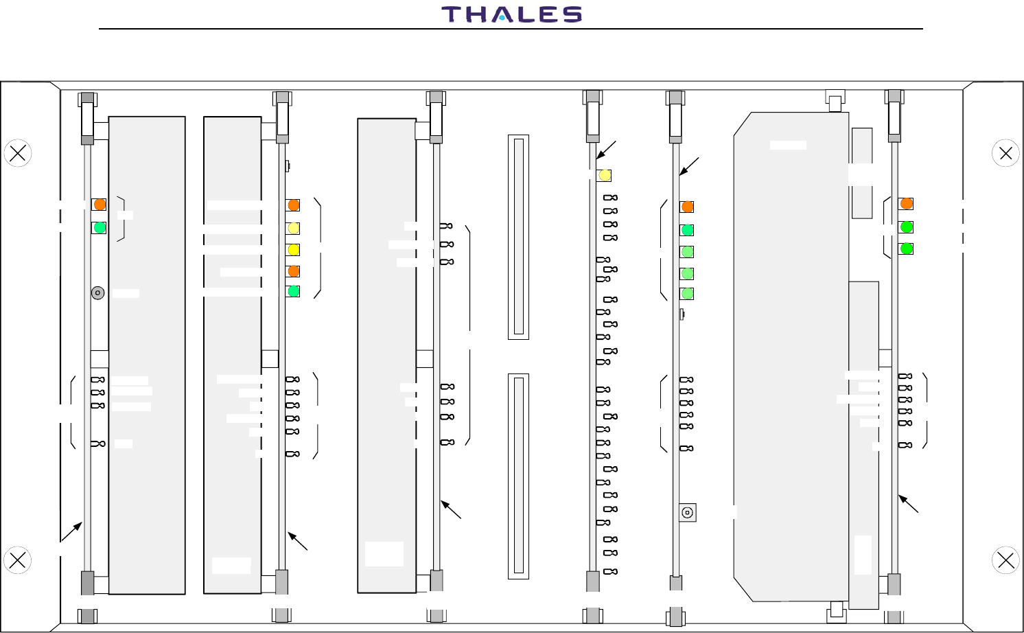
DME 415/435 -Technical Manual
Vol. 1-Section 3 - Operation & Use 955 900 031 C
Vers. D, September 2005 THALES Italia S.p.A.- A. S. D. 3-37
3-37
Digital
Processor
IDENT.(yellow)
TOA N
MOD ST
MD
CAL
SQIDBP
GND
DPNPSQ
DEADT
MORCO
SQI
D
P
R
LOG
GND
SPINH
N.U.
IDT
OVRL
N.U.
N.U.
TRGOUT
RXINH
GF
AGRDW
AGREN
NPR
TH_COMP
DISCH
DISAB
DPR
WDOG
(red)
MOD
(green)
CAL
(green)
COD
(green)
CHK
(green)
D
M
D
PBA
LED
Test
points
DMD
Modulator
PBA
TX
GND
RF PROT (red)
RF ON (green)
DC/DC ON (green)
DC/DC OUT
V MOD
MOD P - N.U.
MOD SQR
RF DET
T
X
DC/DC
converter
Heat Sink
RF circuits
casting
PBA
Test
points
LED
Transmitter/driver
GND
CALIB
MOD N
RXINH
RF ON
TRIG
Receiver
TOA P
LOG N
LOG P
CAL
GND
PBA
RX
OCV analog
OCV gate
R
X
RF and IF
circuits
casting
Test
points
Monitor
H MORse COde
A MOD
MEAS. SYNC
OUT MUX
GND
M
O
N
PBA
MON
LED
Test
points
RF circuits
Casting
Power
Supply
INPUT (green)
PWS FAULTY (red)
RESET
GND
TP2 +15V
TP1 +5V
TP3 -15V
P
W
S
PBA
PWS
Test
points
LED
SW1
WATCH DOG (red)
MORse COde (yellow)
TRX ALARM (yellow)
MON FTY (red)
EXEC. MON (green)
CM1
Pushbutton
TRx on ANT.
RESET
RESET
LM INT
Figure 3.37. LED indicators on transponder modules
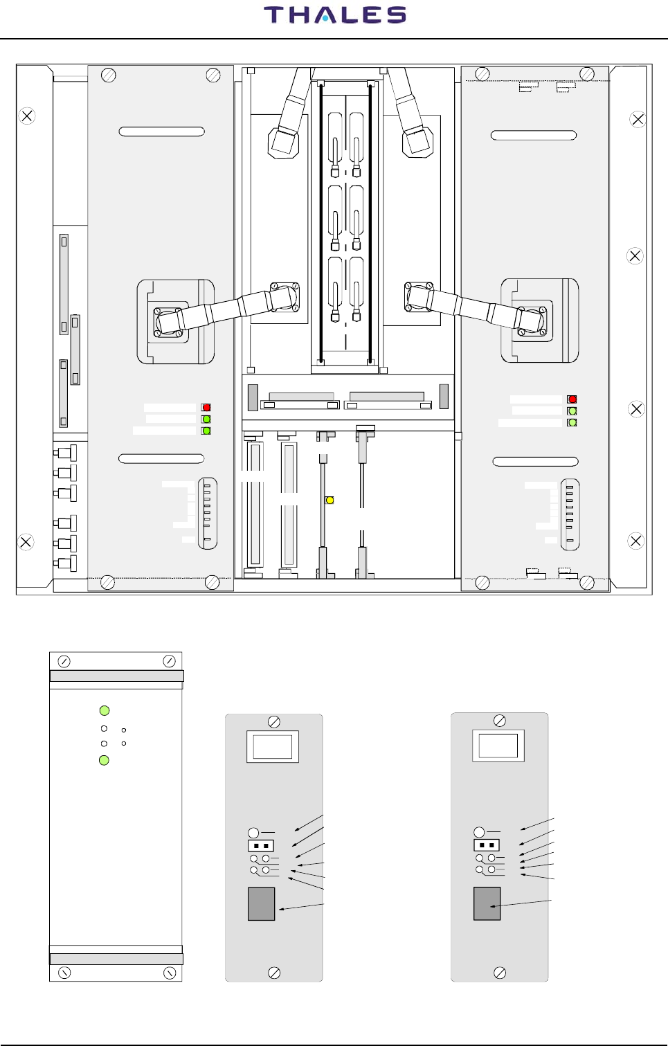
955 900 031 C DME 415/435 -Technical Manual
Vol. 1-Section 3 - Operation & Use
3-38 THALES Italia S.p.A.- A. S. D. Vers. D, September 2005
AFI
DPX 2
DPX 1
OUT OUT
IN IN
TKW 1 TKW 2
Identity
facility
(yellow)
RF PROT (red)
RF ON (green)
DC/DC ON (green)
DC/DC OUT
V1
V2
V3
V4
V5
RF DET
GND
RF PROT (red)
RF ON (green)
DC/DC ON (green)
DC/DC OUT
V1
V2
V3
V4
V5
RF DET
GND
OUT
IN
I/O
MDM1
MDM2
M
O
N
R
X
P
I
L
O
T
TAI
dummy
Figure 3.38. LED indicators on 1 kWp RF amplifiers and AFI modules
AC/DC
Module OK
Mains OK
V adj
-TP
+
-
TEST
SERV
ANS
M1
S1
PM1
LGM 28,8
LED
OFF HOOK = blinks
Earphone connector
Data/Test button
LED ON=test activated
LED ON=DTE is ready
LED ON=MODEM is ready
Telephone access jack
TEST
SERV
M5
M2
S2
PM1 LED RTS & DSK
blinks= MODEM deactivates
LED CTS
LED CD
LED Test
LGM1200
Telephone access jack
Data/Test button
Earphone connector
Figure 3.39. LED indicator on AC/DC power supply module and on the MODEM

DME 415/435 -Technical Manual
Vol. 1-Section 3 -Operation & Use Ref. 955 900 031 C
Vers. D, September 2005 THALES Italia S.p.A.- A. S. D. 3-39
3.4 I/O FUNCTIONING
The equipment can be controlled form the site where the beacon is installed (local site) or from a remote
station (remote site).
At the local site, the equipment can be controlled thorough direct use of the controls on the LCSU Front
Panel or using a PC (Personal Computer) connected to the PC RS-232 connector or SK1 of I/O panel.
Usually, the priority of remote connections is lower than that of the local connections (default condition)
At the local site equipment control, priority is: Control Panel and lastly PC connected to the LCSU unit.
The local operator can activate local commands using the REQUEST RELEASE button, thereby disabling
any commands received from a remote operator. The indications remain active on all the remote stations
connected.
From the remote site, the equipment can be controlled via a PC connected directly to the LCSU unit through
a switched or dedicated line modem.
Operation mode Intrusive or detailed, Line monitoring, Maintenance and so on, are allowed only using a PC
(in Local or Remote site) connected in any mode (directed, trough interposed RCSI/RCSE/MCS, Switched
line and so on)
A detailed description of the permissible operations of the PC with supervisor program is used, is given in
next paragraphs and APPENDIX sections.
3.5 USER SOFTWARE INSTALLATION ON PC
3.5.1 General
The use of usual PC standards and operating systems ensures a familiar operating environment for the
user.
The most important status displays and control functions are also provided on the station’s front local control
unit (LCSU) so that operation is easy also without a PC system connected. Using a PC connected to
connector SK1 - RS-232 (PC) with a user program (WINSV, WINDME400 or MCS) all informations are
provided.
The dialog software represents the core of the operation devices. All control, monitoring, and maintenance
functions are represented on the screen in colors, in the form of menus. They are carried out in control
windows by means of functional keys or mouse control.
Via an online help function texts explaining functions or screen masks can be requested and, if required,
printed out. The user software interprets the operating data input by the operator, checks it for plausibility,
formats it into a specified format, and transmits it to the respective system or subsystem components
(monitor, transmitter). This operating data and the data for remote maintenance is input via the keyboard of
a personal computer (PC desktop or laptop) by authorized operating personnel of the respective operator
(usually air traffic control authorities).
System control can be ensured via the PC with the same software both in local mode in direct connection to
the system and in remote mode via a modem link. Depending on the selected modem, the data can be
transmitted via a switched line or a dedicated line. If a switched line is used the subsystem is automatically
selected by the remote station if the selection on the PC has been made accordingly.
Status information of the subsystem is represented on the PC screen in an easily interpretable form. Via a
printer connected to the PC system data can be printed out and thus documented.
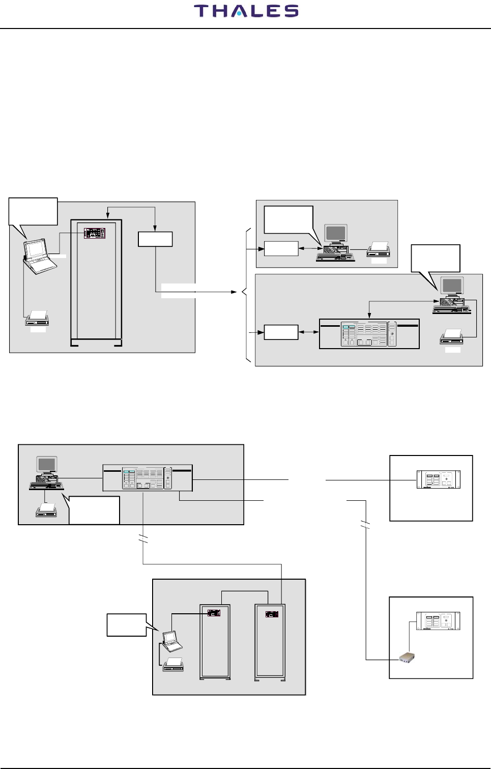
955 900 031 C DME 415/435 -Technical Manual
Vol. 1-Section 3 - Operation & Use
3-40 THALES Italia S.p.A.- A. S. D. Vers. D, September 2005
3.5.2 PC user programs INSTALLATION
NOTE: The connection and control of the PC and the operating system software are to be carried out in
compliance with the manufacturer documentation. It is assumed that the user is familiar with the basics of
PC hardware handling, floppy disk handling, and the operating system (WINDOWS 95 or NT). The
respective handling instructions in the manufacturer documentation must be observed.
The connection of the PC is established via RS232 serial cable. For local mode, the cable is connected to
the RS-232 terminal on the front panel (LCSU) or SK1 of I/O Panel of the DME cabinet.
Examples of programs references to be installed on PC are in figures 3.40, 3.41, 3.42, Errore. L'origine
riferimento non è stata trovata.
"REMOTE" PC
TELEPHON LINE
REMOTE CONTROL RCSI or RCSE
Internal
or External
MODEM
MODEM
"REMOTE" PC
PC
"LOCAL"
(laptop or
desktop type)
DME
RCS I 446
EQUIPMEN T RCSI
12
DETAILED STATUSMAIN STATUS
COMMAND
MODEM
RS-232C -SERIAL LINE
switched or dedicated line
Printer
Internal
or External
Printer
Printer
(e.g.COM1)
PC Programs:
WINSV
WIN DME
or MCS program
PC Programs:
WINSV
WIN DME
or MCS program
PC Programs:
ADRACS
WIN SV ADRACS
WIN DME
Figure 3.40. Examples of PC user programs with DME stand alone
REMOTE CONTROL STATUS INDICATOR
RCSI 446-2 STATUS INDICATOR
SI 446 - 2
RCSI 446
WARNING
NORMAL
ALA RM
1
ON
SIL
LAMP
TEST
EQUIPMENT STATU S SI
WARNING
NORMAL
ALARM
2
RS 232
DME
(D)VOR
EQUIPMENTS LOCAL SITE
CENTER CONTROL ROOM
DEDICATED LINE
CONTROL TOWER
EQUIPMENT RCSI
12 DETAILED STAT USMAIN STAT US
COMM AND
STATUS INDICATOR
SI 446 - 2
WARN ING
NORMAL
ALA RM
1
ON
SIL
LAMP
TEST
EQUIPMENT STATU S SI
WARNING
NORMAL
ALA RM
2
Switched or dedicated teleph. LINE
Modem
RS 232
RS 422/485
RS 422 (<1km)
PC Programs:
ADRACS
WIN SV ADRACS
WIN DME
PC Programs:
WINSV
WINDME
Figure 3.41. Examples of PC user programs in VOR-DME system
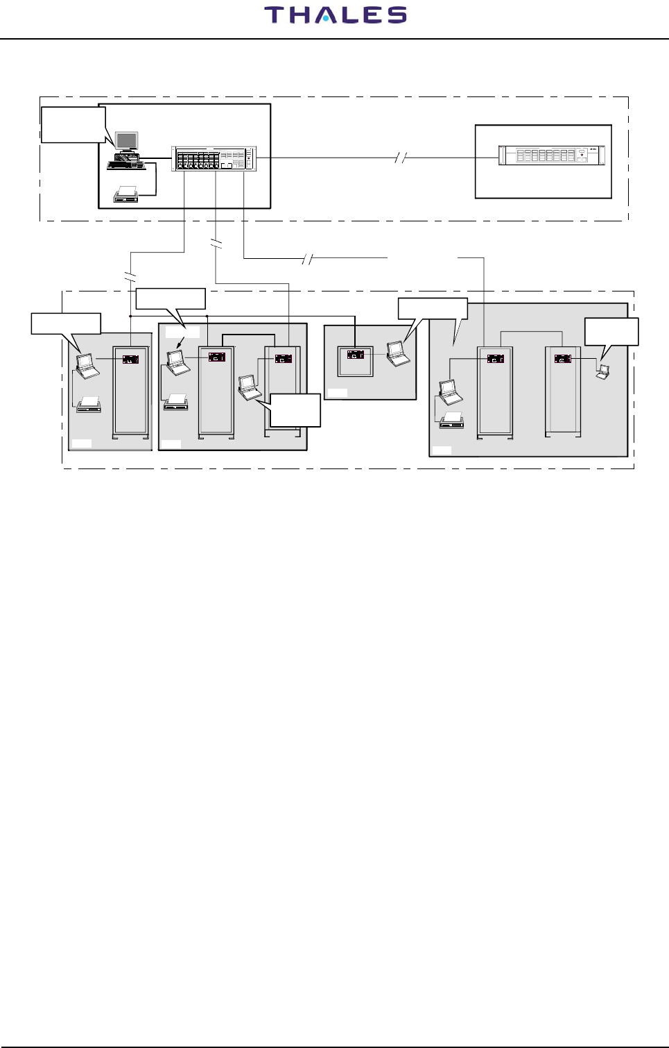
DME 415/435 -Technical Manual
Vol. 1-Section 3 -Operation & Use Ref. 955 900 031 C
Vers. D, September 2005 THALES Italia S.p.A.- A. S. D. 3-41
STATUS INDICATOR
SI 446-8 or RCSE/CTU
RS 422 (< 1 Km.)
REMOTE CONTROL
RCSI 446-8 or RCSE
2
AL AR M
NORMAL
WARNING
TEST
LAM P SI L
ON
1
ALAR M
NORMAL
WARNING
4
AL AR M
NORMAL
WARNING
3
ALAR M
NORMAL
WARNING
6
AL AR M
NORMAL
WARNING
5
ALAR M
NORMAL
WARNING
8
ALAR M
NORMAL
WARNING
7
AL AR M
NORMAL
WARNING
EQUI PME NT STA TU S SI
L2 - DEDICATED
RS 232
DME
(D)VOR
DME
GP
ILS
LOC
ILS
MARKER
RS 232
SELE CT
WARNING
NORMAL
DATA COM
ALARM
SELE CT
WARNING
NORMAL
DATA COM
ALARM
SELE CT
WARNING
NORMAL
DATA COM
ALARM
SEL E CT
WARN I NG
NORMAL
DATA COM
ALARM
SEL E CT
WARNING
NORMAL
DATA COM
ALARM
SEL E CT
WARN I NG
NORMAL
DATA COM
ALARM
SEL E CT
WARNING
NORMAL
DATA COM
ALARM
SEL E CT
WARNING
NORMAL
DATA COM
ALARM
EQUI PME NT R CS I
RCSI 446
12345678
DE T A I LE D STATUSMAIN STATUS
REQUEST
RELEASE
MON 1
STAND BY
MON 2 TX 1
ON ANT
FAULTY
WARNING
TX 2
ON ANT
FAULTY
WARNING
OPERATION
WARNING
DATA COM
SIL
FAULTY
BYPA SS ED
FAULTY
BYPA SS ED
OTHER WA RN
ANT FT Y
ENV ALRM
MAINS OFF
ENA BL E D
ENGAGED
STATIONCONTROL
CHANGE
OVER
EQU IP
ON/OFF
COMMAND
ST AN D BY
RS 232
REMOTE SERVICE MAINTENANCE
CONTROL TOWER
CONTROL CENTER
EQUIPMENTS LOCAL SITES
or SWITCHED LINE
DEDICATED LINE - L3
L1 - DEDICATED LINE
Party Line
Site 1 Site 2
Site 3
Site 4
PC Programs:
ADRACS
PC Programs:
ADRACS
WIN SV ADRACS
WIN DME
PC Programs:
ADRACS
PC Programs:
ADRACS
PC Programs:
ADRACS
PC Programs:
WINSV
WINDME
PC Programs:
WINSV
WINDME
Figure 3.42. Examples of PC user programs with multi-sites
For installation on PC of the MCS program to see the suitable technical manual
3.5.2.1 PC REQUIREMENTS
The user operating software must be installed on a PC system. The PC must meet the recommended
requirements described on APPENDIX B in this volume.
3.6 INSTALLATION ON PC OF USER OPERATING PROGRAM
Detailed procedures of installation are on APPENDIX "B" of this volume
a) User programming on Floppy disk
The PC Supervisor software to be installed first and it is supplied on 3,5” floppy disks.
NOTE:
a) It is recommended to make a backup of the original floppy disks prior to installation.
b) Selection and processing of windows and displays follows the usual instructions according to the
WINDOWS manual.
c) To avoid bringing in a computer virus it is not allowed to run computer games generally and to
use software programs, which are not authorized on the Maintenance Data Terminal (PC). It is
recommended to test the computer or disks with a virus checker.
The disks required to install the "PC supervisor" program are on para B.3 of ANNEX "B" in this volume
NOTE: The disk labeled as "UTIL" is used for the LCSU configuration. (see para. 3.2.2).

955 900 031 C DME 415/435 -Technical Manual
Vol. 1-Section 3 - Operation & Use
3-42 THALES Italia S.p.A.- A. S. D. Vers. D, September 2005
b) User programming on CDROM (one disk)
To install on PC the programs ODBC, WinSv or Adracs WinSv and WinDME400 is sufficient to insert the
disk supplied, in CDROM drive of the PC and to follow the indications which appear on the screen of the
PC screen. The disk is prepared for the execution in AUTORUN.
For detail to see APPENDIX "B" on this volume
3.6.1 "PC Supervisor" program composition
The procedures of installation on PC and the Windows programs are described in the sections APPENDIX
B, C, D of this volume:
- APPENDIX B User Programs WINDOWS for PC - WINSV SUPERVISION
- APPENDIX C User Programs WINDOWS for PC SUPERVISION WINSV ADRACS
- APPENDIX D User Programs WINDOWS for PC - WINDME400, CONTROL of the EQUIPMENT, DME
415/435
- if the equipment were supplied complete of PC, standard programs necessary, operational system and
user's programs relating to the system beacon, they were already installed on the hard disk by the
manufacturer.
3.6.1.1 Windows SuperVisor (WINSV)
The Windows Supervisor is a software that is able to simultaneously display several sites where one
or more equipments can be installed.
It must be used to control DME, TACAN and NDB equipments when DVOR and ILS are not present
in the system configuration; otherwise you must use Adracs WinSv Windows Supervisor program.
To see the status and to control an equipment, it's also necessary to load its correspondent software
manager (e.g. Windows DME/N Equipment Manager).
Operation and install program: see APPENDIX B - WINSV-32 in this volume
3.6.1.2 WinSv ADRACS Windows Supervisor
The WinSv ADRACS Windows Supervisor has the same function of the Windows Supervisor, but
must be used when in the system configuration DVOR or ILS 400 series nav-aide equipments are
also present.
ADRACS = Automatic Data Recorder And Control System
Operation and install program: see APPENDIX C – WINSv ADRACS SUPERVISOR" in this volume
3.6.1.3 Windows DME/N Equipment Manager - WINDME/N-32
The operating instructions concern the use of the control program of the DME 415/435 equipment.
The program works in a Windows environment and makes it possible to display the information
concerning the DME 415/435 equipment for which control has been acquired through a series of
pull-down menus, typical of Windows applications.
The examples described refer to model DME 435 (1 kW output power), but they are also valid for
model DME 415 (100 W output power).
Operation and use program: see APPENDIX D - WINDME/N-32 "Equipment Manager" in this
volume
3.6.1.4 MCS programming
Operation and use program: to see the suitable Technical manual MCS

DME 415/435 -Technical Manual
Vol. 1-Section 3 -Operation & Use Ref. 955 900 031 C
Vers. D, September 2005 THALES Italia S.p.A.- A. S. D. 3-43
3.7 FIRST SWITCHING ON
CAUTION
Make sure that the antenna or adequate dummy loads are correctly connected to antenna
connector. Make sure that inside to equipment the internal dummy load is correctly connected
a) Verify:
• that beacon set-up is as required.
• that the modules are correctly inserted, connected and secured.
• that power supply and ground connections to the antenna and to the other equipment connected to
the beacon, if any, are correct.
• that the calibration of peak power was checked for the operational channel, like procedure in
paragraph 5.3.4 and 5.3.5 of section 5 - MAINTENANCE - in this volume.
b) On module CSB, to insert the M1 jumper, link of activation of the battery of maintenance of memories
RAM
c) Checking of the jumpers positioning on each module, as by tables of section 2 - Installation - in this
volume
d) Check the voltages value of the mains and the battery.
Power the beacon ON by means of the breakers provided on the external electrical switchboard (mains
or external 48vdc or both)
e) The indications on the control and status panel light up.
Press the key LAMP TEST present on the Control panel and to check the lighting of all the LED and the
activation of acoustic alarm (BUZZER)
NOTE: The LCSU has been configured with the necessary programs standard by the manufacturer. If it
is necessary to change or modify the installed configuration to refer at the para 3.2.2 "LCSU
CONFIGURATION PROCEDURE"
- To change from Remote Control to Local Control use key REQUEST RELEASE on the
control and status panel.
- Maintenance operation is only necessary when operational values have to be adjusted on the
transmitter or when a maintenance check has to be performed. It is carried out using the
maintenance control unit (PC).
- Acoustic Alarm
- When the SIL key is pressed, the acoustical alarm stops (F4 on PC keyboard).
Since the monitor carries out normal checks of function and accuracy, the operation of the
installation is faultless when the control and status panel indicates NORMAL. If however the
control and status panel shows WARNING or ALARM, a check of the installation via PC is
possible after pressing the REQUEST RELEASE key to change from local to remote control.
f) Open the cabinet front door and check for LED indication as described in paragraph 3.3 and table 3-10:
the LED green OK, LED red off
g) Power the PC on.
h) Load the user programs onto the PC hard disk, if necessary, as described on "Supervisor (WINSV-32)
program Installation" of APPENDIX B or "WIN 32 ADRACS Supervisor" of APPENDIX C in this volume.
NOTE: If the equipment has been supplied with PC included, the necessary enable programs standard
have already been installed on the hard disk by the manufacturer.
i) Select the SYSTEM CONFIGURATION and make sure the different optional parts are correctly selected
in accordance with the current beacon configuration.
j) Restore the beacon automatic control and verify that no warning or alarm message is displayed.

955 900 031 C DME 415/435 -Technical Manual
Vol. 1-Section 3 - Operation & Use
3-44 THALES Italia S.p.A.- A. S. D. Vers. D, September 2005
k) Perform all diagnostic procedures on the transponder connected to the antenna, wait till they are
over and check for any malfunction message.
l) Change the transponders over, perform the diagnostic procedures on the second transponder (if
present) and check for any malfunction message at the end of these procedures.
m) Make OFF the equipment while pressing on key EQPT ON/OFF and to check the extinction of the
green LED "NORMAL".
n) Checking the beacon in absence of mains (black-out condition). With related batteries connected to
open the 220Vac line of mains: the functionality of the equipment should not be degraded. To
restore the mains after this test.
o) Switch the equipment in automatic mode
On section 5 "Maintenance" in this volume it describes procedures and suggestions in the event of
damages or faulty persistent operations.
3.8 POWER OFF PROCEDURE
These operations are:
a) the beacon operation is interrupted and as a result no signal will be radiated by entering the OFF
command in automatic mode or the beacon STBY in Maintenance mode, provided in the main menu. Or
by pressing the BEACON ON/OFF pushbutton, on the Control Panel, after taking control of beacon
operation by means of the EQUIP ON/OFF pushbutton on the same panel.
The indications on the Control Panel are also active after beacon STBY or beacon OFF
NOTE: The power supply of regulated voltage +5V and ±15V are continuously present: the "stand by"
or "Beacon OFF" commands stop the RF signal radiated only and not the low voltages.
b) All power supply voltages may then be disabled by pressing the two breakers provided on the external
electrical switchboard.
Then switch the PC in OFF by means of the suitable on/off switch.
In this case all power supply voltages are disabled and the indications on the control and status panel,
extinguish.
NOTE: Executing the command: EQUIP ON/OFF from remote control it is possible to switch off the radiated
signal of the beacon on condition that, in local site, the command REQUEST/RELEASE is in remote
position (illuminated indication ENGAGED).

THALES Italia S.p.A.- Air Systems Division
Description, Installation, Operation, Maintenance Reference: Vol. 1 Code 955 900 031 C
GROUND BEACON
DME 415/435
Technical Manual
VOLUME 1
Equipment description, Installation, Operation, Maintenance and PC user
Vers. D, September 2005
SECTION 4
TECHNICAL SPECIFICATIONS

955 900 031 C DME 415/435 -Technical Manual
Vol. 1-Section 4 - Technical Spec.
4-II THALES Italia S.p.A.- A. S. D. Vers. D, September 2005

DME 415/435 -Technical Manual
Vol. 1-Section 4 - Technical Spec. 955 900 031 C
Vers. D, September 2005 THALES Italia S.p.A.- A. S. D. 4-a
Table of CONTENTS
Paragraph Page
SECTION 4............................................................................................................................................4-1
TECHNICAL SPECIFICATIONS ........................................................................................4-1
4.1 General .............................................................................................................................4-1
4.1.1 Applicable Documents: .....................................................................................................4-1
4.2 ENVIRONMENTAL and SERVICE CONDITIONS ...........................................................4-1
4.3 PHYSICAL CHARACTERISTICS .....................................................................................4-1
4.3.1 Equipment Versions..........................................................................................................4-2
4.4 GENERAL FEATURES and TYPE of SERVICES............................................................4-2
4.4.1 Type of Services ...............................................................................................................4-2
4.4.2 Coverage and Accuracy....................................................................................................4-2
4.4.3 Radio frequency and polarization .....................................................................................4-2
4.4.4 Nominal Reply Delay – Pair Pulse Code – Channeling....................................................4-2
4.4.5 Reply Efficiency ................................................................................................................4-3
4.4.6 Traffic Capacity .................................................................................................................4-3
4.4.7 Reply Delay.......................................................................................................................4-3
4.4.8 Automatic Stabilization of the Reply Delay.......................................................................4-3
4.4.9 Reliability...........................................................................................................................4-4
4.5 EQUIPMENT DATA ..........................................................................................................4-4
4.5.1 TRANSMITTED signal ......................................................................................................4-4
4.5.1.1 Pulse shape ......................................................................................................................4-4
4.5.1.2 RF Pulse Signal Spectrum................................................................................................4-4
4.5.1.3 Out of Band Spurious Output............................................................................................4-5
4.5.1.4 In-Band Spurious Output ..................................................................................................4-5
4.5.1.5 Harmonics.........................................................................................................................4-5
4.5.1.6 Peak Power Output...........................................................................................................4-5
4.5.1.7 Transmitted Pulses ...........................................................................................................4-5
4.5.1.8 Replies to Valid Interrogations..........................................................................................4-5
4.5.1.9 Identification Using Morse Code.......................................................................................4-5
4.5.1.10 Squitter Output Pulses......................................................................................................4-6
4.5.1.11 Transmission Priority ........................................................................................................4-6
4.5.2 RECEIVER AND PROCESSOR CHARACTERISTICS....................................................4-6
4.5.2.1 Receiver Sensitivity...........................................................................................................4-6
4.5.2.2 Receiver Dynamic Range .................................................................................................4-6
4.5.2.3 Sensitivity Variation with Pulse Coding.............................................................................4-6
4.5.2.4 Sensitivity Variation with Frequency .................................................................................4-6
4.5.2.5 Sensitivity Variation with the Interrogation Load...............................................................4-7
4.5.2.6 Sensitivity Variation due to Interrogations on the Adjacent Channel................................4-7
4.5.2.7 Recovery Time..................................................................................................................4-7
4.5.2.8 Continuous Wave (CW) Signal Interference.....................................................................4-7
4.5.2.9 Spurious Suppression.......................................................................................................4-7
4.5.2.10 Decoding Dead Time ........................................................................................................4-7
4.5.2.11 Echo Suppression.............................................................................................................4-7
4.5.2.12 Receiver Bandwidth ..........................................................................................................4-8
4.5.2.13 Interrogation Overload ......................................................................................................4-8
4.5.2.14 Receiver Inhibition during Transmission...........................................................................4-8
4.6 MONITORING SYSTEM...................................................................................................4-8
4.6.1 General .............................................................................................................................4-8

955 900 031 C
DME 415/435 -Technical Manual
Vol. 1-Section 4 - Technical Spec.
4-b THALES Italia S.p.A.- A. S. D. Vers. D, September 2005
Paragraph Page
4.6.2 Executive Monitoring ........................................................................................................ 4-9
4.6.2.1 Executive Monitoring Terms............................................................................................. 4-9
4.6.2.2 Monitor Insertion Delay .................................................................................................... 4-9
4.6.2.3 Monitor Response to Alarms............................................................................................ 4-9
4.6.3 Monitor Self-check............................................................................................................ 4-10
4.6.4 Routine Checks ................................................................................................................ 4-11
4.6.4.1 Monitors Routine Check ................................................................................................... 4-11
4.6.5 Manual tests ..................................................................................................................... 4-11
4.6.6 Diagnostics ....................................................................................................................... 4-12
4.7 LOCAL I/O SYSTEM ........................................................................................................ 4-13
4.8 Duplexer and RF path ...................................................................................................... 4-13
4.9 POWER SUPPLY REQUIREMENTS .............................................................................. 4-14
4.9.1 Consumption: ................................................................................................................... 4-14
4.9.2 Power supply PWS module: +5V and ± 15V.................................................................... 4-15
4.9.3 BCPS subrack and AC/DC module.................................................................................. 4-15
4.10 ANTENNA ........................................................................................................................ 4-17
4.10.1 Omnidirectional FAN 96 type ........................................................................................... 4-17
4.10.2 Sectorial FAN-88 .............................................................................................................. 4-18
List of TABLES
Table Page
Table 4.1 Channel code, pulse code, reply delay.................................................................................4-3
Table 4.2 DME 415/435: Executive Monitoring .................................................................................... 4-10

DME 415/435 -Technical Manual
Vol. 1-Section 4 - Technical Spec. 955 900 031 C
Vers. D, September 2005 THALES Italia S.p.A.- A. S. D. 4-1
SECTION 4
TECHNICAL SPECIFICATIONS
4.1 GENERAL
Equipment DME 415/435 is a ground beacon located in a subrack of 19", equipped with two transponders
and a system dual monitoring, microprocessor controlled.
This equipment can be also configured like DME/N for 100Wp (DME 415) or 1kWp (DME 435).
The following characteristics are valid for the two configurations if that is not specified differently.
4.1.1 Applicable Documents:
The DME ground beacons comply with the following specifications:
− ICAO Annex 10, 5th edition, International Standard and Recommended Practices
− EUROCAE ground DME, MPS (Minimum Performance Specification), ed.57, Iss. December 1986.
− C E directives for Transceiver ETS 300 339 (EMC)
EN 60065 – EN6215 (Safety)
− EEC Directives for CE marking: EMC/89/336
Electrical Safety/73/23.
4.2 ENVIRONMENTAL AND SERVICE CONDITIONS
The optimal environmental conditions for beacon operation are given below:
− Temperature operation indoor: from −10°C to +55 °C.
− relative humidity: up to 95% (-10 to +35°C); max 60% (> 35°C);
− pressure: from 760 to 500 millimeters of mercury from sea level to an altitude of approximately 3000
meters; if the equipment is to be installed on sites at even greater altitudes, consult the manufacturer.
As regards beacon storage and transport, the temperature must be within the limits −40 °C and +70 °C and
pressure up to 15000 m.
4.3 PHYSICAL CHARACTERISTICS
The beacon physical characteristics of the equipment single 19" standard cabinet are as follows:
− height: 1730 mm;
− width: 580 mm;
− depth: 610 mm (cabinet code 297 509 004); 635 mm (cabinet code 297 509 007) ;
− weight: approx. 145 kg DME 415 (optional modules included).
approx. 165 kg DME 435 (optional modules included)
Completely modular with plug-in module type. Plug-in units are used as double or single Euroform printed
multi-layer circuit boards, with dimensions of 233.4 x 220 [mm] or 100 x 220 [mm] accommodate on four
subracks (full version). The RF modules are accurately shielded in casting boxes.

955 900 031 C
DME 415/435 -Technical Manual
Vol. 1-Section 4 - Technical Spec.
4-2 THALES Italia S.p.A.- A. S. D. Vers. D, September 2005
4.3.1 Equipment Versions
The two versions have the same modules and the same of principles of operation.
Approach DME 415 – Solid state 100 Wp to be co-located with ILS
En route DME 435 – Solid state 1kWp to-be co-located with VOR or DVOR
The equipment is configurable in following standard version:
• Full dual: Two Transponders/monitors/duplexers
• Single: One transponder/monitor/duplexer
Other possible configurations are available by request
NOTE: Each version of DME can be assembled in cabinet indifferently with code 297 509 004 or
code 297 509 007
4.4 GENERAL FEATURES AND TYPE OF SERVICES
All the features listed below refer to the DME beacon antenna connector where no other indication is given.
4.4.1 Type of Services
This system provides a method of measuring the direct distance between an aircraft and a selected
transponder within the coverage limits dictated by the operational requirements.
Each DME transponder provides synchronous replies to the DME/N interrogation signals.
4.4.2 Coverage and Accuracy
Coverage can be either omnidirectional or sectorial, depending on the type of antenna selected, and is
determined in relation to the following power densities:
On the transponder antenna: –93 dBW/m2 for DME 415; –103 dBW/m2 for DME435,
On the aircraft antenna: –83 dBW/m2 for the DME/N.
At present, the total accuracy of a DME system can be considered within the maximum values specified
below: ±0.12 NM +0.05% of the distance. From 0 to 65 nautical miles, and ±0.17 NM +0.05% of the
distance, above 65 nautical miles.
4.4.3 Radio frequency and polarization
The transponder antenna is vertically polarized and it radiates in the frequency band ranging from 960 MHz
to 1215 MHz. The interrogation and reply frequencies comply with the ICAO Annex 10 standards.
4.4.4 Nominal Reply Delay – Pair Pulse Code – Channeling
The DME 415/435 beacon is configured as DME/N, it will be possible to select one of the 252 (standard
ICAO) N channels (126 X channels and 126 Y channels: see table 1.2 on section 1 in this volume).
Table 4.1 illustrates the channel code, pulse code, reply delay and operating mode of the various channels.

DME 415/435 -Technical Manual
Vol. 1-Section 4 - Technical Spec. 955 900 031 C
Vers. D, September 2005 THALES Italia S.p.A.- A. S. D. 4-3
Table 4.1 Channel code, pulse code, reply delay
CHANNEL
CODE
NOMINAL
INTERROGATION
PULSE PAIR
SPACING CODE
[µs]
TRANSPONDER
REPLY PULSE PAIR
SPACING CODE
[µs]
TRANSPONDER
NOMINAL
REPLY DELAY
[µs]
X 12 12.0 ± 0.1 50
Y 36 30.0 ± 0.1 56
4.4.5 Reply Efficiency
The Reply Efficiency is better than 70% and internal noise not cause more than 10 pair transmission/s
4.4.6 Traffic Capacity
The DME beacon is always capable of giving distance information to a maximum of 200 interrogating
airborne equipment.
It is however, possible to select two transmissions rates values: ranging from 800 to 4800 ppps or ranging
from 2700 to 4800 ppps.
The difference is given by the minimum number of pulse pairs per second (800 ±50 ppps or 2700 ±90 ppps)
transmitted by the equipment. Even in case of no interrogations from the airborne interrogators; as a result,
the power consumption will be different.
4.4.7 Reply Delay
The reply delay may be defined as the reply interval between an interrogation, in antenna, and the
corresponding reply at the same point.
On a DME/N beacon, the reply delay may be selected in 0.05 µs steps, as follows:
- from 35 µs to 75 µs for X channels;
- from 50 µs to 75 µs for Y channels.
As far as reply delay accuracy according to interrogation level is concerned:
Interrogation level
delay variation
(average) distance accuracy
(average typical)
from –10 dBm to –79 dBm ± 0,2 µs ± 30 m
from –79 dBm to –89 dBm ± 0,4 µs ±60 m
from –89 dBm to –91 dBm ± 0,6 µs ±90 m
4.4.8 Automatic Stabilization of the Reply Delay
The reply delay can be automatically adjusted according to the measurements performed by the monitors
and of specific circuits on the transponder (circuits of pilot pulse) that they measure and they adjourn the
precision of the reply delay in continuity with step of 12,5ns.
The average value of the measurements from both monitors is used to modify the reply delay presetting in
steps of 12,5 ns.
The automatic reply delay stabilization will continue even if one of monitors is faulty, if the monitoring logic
set will permitted.

955 900 031 C
DME 415/435 -Technical Manual
Vol. 1-Section 4 - Technical Spec.
4-4 THALES Italia S.p.A.- A. S. D. Vers. D, September 2005
4.4.9 Reliability
In the calculation of the beacon reliability, all alarms of the monitors have been considered primary and the
monitors in "parallel" configuration. So that both monitors must detect an alarm at the same time in order
to trigger a changeover or a beacon shutdown.
The failure rate of the various modules has been calculated in relation to the to MIL-HDBK-217E in Ground
Fixed conditions at an ambient temperature of 20 °C and of 55 °C. The following values have been
calculated:
MTBF at 20 °C at 55 °C
DME 415, dual station: over 18.000 hrs over 11.000 hrs
DME 435, dual station: over 16.000 hrs over 10.000 hrs
DME 415, single station: over 9.500 hrs over 6.000 hrs
DME 435, single station: over 8.500 hrs over 5.500 hrs
4.5 EQUIPMENT DATA
4.5.1 TRANSMITTED signal
The stability of the transponder radio frequency signal output is better than 0.001 % apart from the nominal
channel frequency.
4.5.1.1 Pulse shape
The characteristics of each pulse transmitted are given below:
- rise time: 2.5 µs with a tolerance ranging between –1 µs and +0.5 µs, measured between the points
where the amplitude corresponds to 10% and 90% of the peak value;
- duration: 3.5 µs with a tolerance ranging between ±0.5 µs, measured between the points where the
amplitude corresponds to 50% of the peak value;
- decay time: never longer than 3.5 µs measured between the points where the amplitude corresponds to
10% and 90% of the peak value;
- pulse top: between the points on the leading and trailing edges of the pulse at which the amplitude is
95% of the maximum, the instantaneous amplitude does not fall below 95% of the maximum voltage
amplitude.
4.5.1.2 RF Pulse Signal Spectrum
The pulse spectrum of the modulated signal is such, that during the pulse the output power, contained in a
0.5 MHz band centered to ±0.8 MHz with respect to the nominal channel frequency. It is not greater than 20
mW, while in the same band, centered to ±2 MHz, it is not greater than 0.2 mW.
Any lobe of the spectrum is of lower amplitude than the adjacent lobe, which is closer to the nominal
channel frequency. The power in the frequency bands is the energy that the frequency band contains,
divided by the time of pulse transmission.
The time of pulse transmission is the interval, measured between the points on the rise and decay edges of
the pulse envelope, at 5% of the maximum voltage amplitude

DME 415/435 -Technical Manual
Vol. 1-Section 4 - Technical Spec. 955 900 031 C
Vers. D, September 2005 THALES Italia S.p.A.- A. S. D. 4-5
4.5.1.3 Out of Band Spurious Output
The spurious output is below -40 dBm/kHz at all frequencies between 10 and 1800 MHz, with the exception
of the frequency band between 960 and 1215 MHz.
4.5.1.4 In-Band Spurious Output
The RF output level in the interval between transmission of pulse pairs is at least 80 dB lower than the
maximum power level during the pulses. In addition, between the pulses of each pair, there is an interval of
at least 1.0 µs during which the RF output level and is at least 80 dB lower than the maximum power level of
each pulse. Finally, the CW output signal does never exceed 5 mW.
4.5.1.5 Harmonics
The output power of CW harmonics of the carrier frequency does not exceed -10 dBm. In addition, the peak
of any harmonic of the carrier does not exceed +20 dBm.
4.5.1.6 Peak Power Output
The transponder output power at the peak of each pulse is not less than 100 Wp for DME 415 and not less
than 1kWp for DME 435.
It is possible to reduce this power value to 50 Wp ± 1dB (DME 415) and to about 500 Wp ± 1dB (DME 435),
programmable a step of 1dB.
4.5.1.7 Transmitted Pulses
Only pulse pairs are transmitted. Each transmitted pulse pair is coded accordingly to the operation channel.
The difference between the peak power levels of the pulses of any pulse pair does not exceed 1 dB.
The difference between the peak power levels of the pulses of each pulse pair (squitter or reply) does not
exceed 1 dB.
4.5.1.8 Replies to Valid Interrogations
Replies to valid interrogations have a nominal reply delay for the operating channel, as indicated in table
4.1.
Any differences from the nominal reply delay do not exceed the following values:
- ±0.2 µs BIAS and ±0.2 µs NOISE, on a basis of 95 % for interrogations having any level between -5 and
-81 dBm.
- ±0.4 µs BIAS and ±1 µs NOISE for interrogations having levels between -81 and -91 dBm.
4.5.1.9 Identification Using Morse Code
The identity signal (ID) consists of pulse pairs transmitted at a constant rate of 1350 (±0.2 %) per second
during the key down time express in code Morse international
The characteristics of the identity code transmission rate for the DME transponder are as described below.
The dots have duration of 100...160 ms with a tolerance of ±5 %.
The dashes have duration of three dots.
The interval between the dots and/or the dashes of a character has duration equal to one dot.
The interval between two consecutive characters is not less than three dots.
The maximum duration for the identity code is equal to 64 dots.
The code repetition rate is at least once every 40 s.
The manipulation time with "key down" does not exceed 4 s for each identity group.

955 900 031 C
DME 415/435 -Technical Manual
Vol. 1-Section 4 - Technical Spec.
4-6 THALES Italia S.p.A.- A. S. D. Vers. D, September 2005
4.5.1.10 Squitter Output Pulses
The squitter pulse pairs are automatically generated and controlled to maintain a transponder minimum
transmission rate (replies and squitters) equal to 800 (±50) pulse pairs per second (or 2700±90 pps in case
of pulse transmission ranging from 2700 to 4800 pps).
These pulse pairs are randomly spaced, but their spacing is never less than 200 µs and there is no spacing
in the range from 730 to 750 µs (typical spacing of the identity code).
When the transmission rate is greater than 800 pairs per second (or 2700 pps in the other case), no
squitters are added.
4.5.1.11 Transmission Priority
The transmission of the output signals from the transponder has the following order of priority:
- Identity pulse pairs
- Reply pulse pairs
- Squitter pulse pairs
Transmission priority is established in the following way:
- The identity code inhibits the replies and the squitters as long as the dots and dashes last.
- The decoded pulses inhibit the squitter pulses at the encoder input until the reply is transmitted.
4.5.2 RECEIVER AND PROCESSOR CHARACTERISTICS
The transponder provides the required performance in response to interrogations from the airborne
equipment. The interrogating signals comply with the standards laid down in the ICAO Annex 10 and
EUROCAE MPS.
4.5.2.1 Receiver Sensitivity
When there is no overload, the DME 415 / 435 transponder's sensitivity is typical better than -91 dBm (can
be preset between -76 and -94 dBm via PC keyboard).
The reply efficiency is better than 70%. Under these conditions, the transponder internal noise does not
radiate more than 10 reply transmissions per second.
4.5.2.2 Receiver Dynamic Range
Accuracy is maintained for interrogating signals having levels between receiver sensitivity threshold
selectable values and -5 dBm. The reply efficiency is at least equal to 95%, for a single interrogator with
signal levels of at least 10 dB or more greater than the receiver sensitivity threshold.
4.5.2.3 Sensitivity Variation with Pulse Coding
If the interrogation pulse spacing differs from the nominal spacing value by ±1.0 µs, and there are no further
interrogations, the receiver sensitivity threshold does not decrease by more than 1 dB. Interrogations with a
spacing that differs by more than ±2.0 µs and an interrogating level up to a maximum of -10 dBm are
rejected. Single pulse is not decoded.
4.5.2.4 Sensitivity Variation with Frequency
If there are no other interrogations, the nominal sensitivity threshold value does not decrease by more than
1 dB, when the interrogating signal frequency differs from the nominal value of the operating frequency set
by ± 200 kHz.

DME 415/435 -Technical Manual
Vol. 1-Section 4 - Technical Spec. 955 900 031 C
Vers. D, September 2005 THALES Italia S.p.A.- A. S. D. 4-7
4.5.2.5 Sensitivity Variation with the Interrogation Load
With the echo suppression disabled, and with a decoding dead time of 60 µs, the nominal receiver
sensitivity will not decrease by more than 1 dB, when the number of replies has any value up to a maximum
of 3600 pulse pairs per second.
4.5.2.6 Sensitivity Variation due to Interrogations on the Adjacent Channel
The transponder sensitivity threshold increases by no more than 1 dB in presence of interrogating signals
on the adjacent channel at frequencies of ±900 kHz or more far from the on-channel interrogation frequency
and correctly coded (for the channel in use), at any level up to -10 dBm and at any interrogation rate up to
3600 pairs per second. The transponder does not reply to interrogations on adjacent channels.
4.5.2.7 Recovery Time
The receiver sensitivity will not be reduced by more than 1 dB, when the valid interrogation pairs are
preceded by a single undesired pulse which occurs 8 µs or more before the valid interrogation. The period
between a single undesired pulse and the valid interrogation pair is measured between the 50% points of
the rising edge peak value of the single pulse and the first pulse of the interrogating pair. The single
undesired pulse may have all amplitudes up to a maximum of 60 dB above the receiver sensitivity set. The
above is valid when no echo suppression device is activated.
4.5.2.8 Continuous Wave (CW) Signal Interference
A continuous wave interfering signal on the assigned channel frequency or at any other frequency within the
receiver pass band, with peak power of -100 dBm at the receiver input, does not preclude compliance to
specifications or modify the reply efficiency to interrogations from the value obtained without CW
interference.
4.5.2.9 Spurious Suppression
The signal received at the intermediate frequency (63 MHz) is suppressed by at least 80 dB. Any other
spurious reply or signal in the band between 960 and 1215 MHz and image frequencies are suppressed by
at least 75 dB.
4.5.2.10 Decoding Dead Time
The decoding of each valid pair of interrogation pulses generates a dead time interval during which the
decoder output is disabled, and therefore any subsequent valid interrogations will not be processed and
transmitted, even though they are decoded.
The duration of the dead time interval, which is normally set at 60 µs, can be selected from the range of
values 50 to 150 µs, at 1 µs steps.
4.5.2.11 Echo Suppression
• Short Echo Suppression
Echo pulses which, occur between the pulses of a valid interrogation pair, will not affect the reply timing
by more than 0.15 µs.
In addition, the reply efficiency will not be reduced by more than 10% with respect to the value obtained,
when there are no echo pulses.
This occurs for an interrogating signal with a level between -10 dBm and 10 dB beyond the sensitivity
threshold set for the receiver, and for an echo level up to 3 dB lower than the direct signal level.
• Long Echo Suppression
The long echo suppressing circuits are used to suppress the echo pulses, which fall after the dead time
interval.

955 900 031 C
DME 415/435 -Technical Manual
Vol. 1-Section 4 - Technical Spec.
4-8 THALES Italia S.p.A.- A. S. D. Vers. D, September 2005
These circuits are activated after the decoding of a valid interrogation with an interrogating level, which
exceeds the activation threshold of the long echo suppression circuits. The threshold can be selected
from the values between 0 dBm (deactivated echo suppression circuits) and -60 dBm.
The threshold used for long echo suppression has a level, which is 3 (±3) dB above the interrogating
signal level which activated the echo suppression circuits. It has a duration, which can be selected from
the values between 50 and 300 µs.
4.5.2.12 Receiver Bandwidth
The bandwidth at the 12 dB and 60 dB points do not exceed 2 MHz and 12 MHz respectively.
4.5.2.13 Interrogation Overload
The maximum transponder transmission rate is 4800 (±150) pulse pairs per second.
When overload occurs, the sensitivity of the receiver is automatically reduced to limit the transmission rate
of the transponder. The range of sensitivity reduction is 50dB.
The transmission rate is automatically controlled by simple preventing further replies.
The transponder components are additionally protected if transmission should exceed the maximum rate in
case of malfunctioning.
4.5.2.14 Receiver Inhibition during Transmission
During transmission the receiver is inhibited for a period of time that will not exceed 10 µs for each pulse
transmitted.
4.6 MONITORING SYSTEM
4.6.1 General
The typical monitoring system consists of two independent monitors, controlled by µP and managed by
suitable program.
the two monitors have primarily the function to take measurements whose results, provided to the system of
control, make it possible to check the services of the equipment and emitted signal RF. To take various
measurements one uses pulses produced by the interrogators having the same characteristics as the signal
coming from RF interrogator of the airborne.
The monitors basically perform the following measurements in order to check that the beacon is operating
correctly:
a) Executive monitoring; tests continuously carried out on the transponder output signal.
b) Monitor self-check; additional tests carried out together with the executive monitoring to ensure the
monitor integrity.
c) Routine checks; pre-established tests of the most important parameters of the transponder and of the
monitor itself that can be performed during the normal operation of the beacon; they can be repeated
periodically or when requested by the operator.
d) Manual tests; tests specific for maintenance operations; to perform quantitative measurements on the
relevant parameters while keeping the beacon in normal operation: the operator may select the type
of test.
e) Diagnostics; tests performed in sequence and when requested by the operator, useful to determine
the efficiency of the monitor itself and of the transponder connected to the dummy load.

DME 415/435 -Technical Manual
Vol. 1-Section 4 - Technical Spec. 955 900 031 C
Vers. D, September 2005 THALES Italia S.p.A.- A. S. D. 4-9
4.6.2 Executive Monitoring
This monitoring action, check the output signal of the transponder(s) and generates a condition of alarm as
specified in this section when the predetermined limits are exceeded.
It is continuously carried out for the main transponder connected to the antenna; it can also be carried out
contemporary both for the transponder on antenna and for the transponder on dummy load if the standby
mode selected is "hot".
The operator is supplied with the values of the controlled parameter measurements obtained by both
monitors. These values are continuously updated.
The tests are performed in approx. 1 s; after a pre-defined delay an out of tolerance parameter generates an
alarm condition and as a result the transponders will be changed over or the equipment will be shutdown.
See details on the measurements in the table 4.2.
It is possible to select a AND or OR monitor logic.
- In case of OR monitor logics, both monitors must work correctly to make beacon operation possible.
An alarm condition will occur (beacon shut down) when one monitor detect an out of tolerance
condition of one parameter.
- In case of AND monitor logics, the beacon will keep working even if one of the two monitors is faulty.
An alarm condition will occur when both monitors detect an out of tolerance condition of one
parameter (AND logic=best reliability condition default preset).
4.6.2.1 Executive Monitoring Terms
• A primary alarm starts an automatic sequence of events to inhibit signal transmission and
consequently, restore correct operation by inserting the reserve equipment, if present.
• A secondary alarm starts an automatic sequence of events to provide the proper signaling and
engage the spare transponder if this can provide a better service. A secondary alarm does not inhibit
signal transmission. The measuring period is the interval necessary for acquiring samples of a
parameter.
• The average value of a parameter is calculated in the measuring period.
• The reaction time (time monitors alarms delay) is the interval between an out of tolerance condition
occurring and the changeover or shutdown of the transponder by the controller. The reaction time
takes the monitor and equipment delays into account.
4.6.2.2 Monitor Insertion Delay
The monitors are inhibited for approx. 5 s after the "equipment on" command.
4.6.2.3 Monitor Response to Alarms
After primary or secondary alarms the following operations are performed:
• The transponders are switched or powered off.
• A visual and acoustic alarm is emitted at both the local and remote sites.
• The cause of the alarm is identified (monitor parameter), and the value at the time of alarm is stored.
Switching a Single Transponder
If there is no standby equipment available, the single equipment is deactivated only when the monitors
detect a primary parameter, which is outside of the specified limits. A primary alarm completely interrupts
transmission from the station within the given reaction time.
Switching Dual Equipment
When there is a standby equipment available, switching guarantee that service continues with the best
available hardware, including the secondary alarm conditions.
A secondary alarm on the operating transponder causes the equipment to be switched only if the
standby transponder's conditions are perfect.
Standby Mode
The standby mode of the transponder connected to the dummy load can be set to:
- Normal : Transmitter is off.
- Hot : Transponder is operating.

955 900 031 C
DME 415/435 -Technical Manual
Vol. 1-Section 4 - Technical Spec.
4-10 THALES Italia S.p.A.- A. S. D. Vers. D, September 2005
To table 4-2 are deferred, for each parameter, the alarm threshold, the measuring accuracy, the reaction
time as well as the procedure of measurement. The parameters to which corresponds a secondary alarm
can be redefined individually in way such as the condition of alarm which is associated to them the primary
type
Table 4.2 DME 415/435: Executive Monitoring
PARAMETER ALARM
TYPE ALARM
THRESHOLD TEST
ACCURACY MONITORS
ALARMS
DELAY
TEST
METHOD
REPLY DELAY Primary ±0.1 µs
(adjustable at
±0.4 µs max.)
±20 ns 4 s
(adjustable
from 1 to 10s)
Average of 32 tests obtained by
interrogating with 40 ppps and -
40 dBm ±2 dB level
REPLY PULSE
SPACING
Primary ±0.25 µs ±20 ns 4 s
(adjustable
from 1 to 10s)
4 tests are averaged every
second
REPLY PULSE
POWER
Primary −3 dB ±0.5 dB 4 s
(adjustable
from 1 to 10s)
4 tests are averaged every
second
TRANSMISSION
FREQUENCY
Primary ±200 ppm ±50 ppm 4 s By means of the counter
TRANSMISSION
RATE
Secondary
(selectable
to primary)
720 ppps ±20 ppps 10 s By means of the counter
IDENTITY CODE Secondary
(selectable
to primary)
− − − Enabled alarm if the identity
code unit is delayed by more
than 1 cycle Alarm at 2nd cycle
after the last valid cycle.
REPLY
EFFICIENCY
Secondary
(selectable
to primary)
66% ±2% 10 s Replies to 50 inter-rogations at
a level 6 dB (±2 dB) greater
than the receiver sensitivity
threshold; updated approx.
every 2.5 s
Note 1: The secondary alarm parameters can be set individually to operate as primary alarms and the
reaction time for each alarm can be preset between 1 and 10 s.
Note 2: The reply delay alarm limit can be adjusted up to 0.4 s on request of the user.
Note 3: The number of interrogations generated by the monitor system does not exceed 120 per second.
4.6.3 Monitor Self-check
Each monitor is kept under constant control to check its operation in order to avoid false alarm detection.
This is done by performing suitable tests, which are repeated every second. If the monitor fails to pass all
tests, it is declared faulty and deactivated within 1 s.
The following tests are performed:
• Frequency synthesizer
• Interrogator
• IF detector
• AD and DA converters
• Timers and counters
• Morse Code detector
• Digital circuits (µP, RAM, Eprom).

DME 415/435 -Technical Manual
Vol. 1-Section 4 - Technical Spec. 955 900 031 C
Vers. D, September 2005 THALES Italia S.p.A.- A. S. D. 4-11
4.6.4 Routine Checks
A routine check is carried out on request or periodically at intervals, which are preset by the operator. It
performs quantitative measurements of the transponder and monitor parameters; the results can be stored
in the database of the equipment.
These measurements do not affect or delay the normal monitoring and do not alter the beacon's
performance:
- Reply delay at interrogation levels of : -10; -30; -50; -71 dBm, and 3 dB above the sensitivity threshold.
- Spacing between the reply pulses.
- Pulse peak power
- ERP of the 1st and 2nd pulse and peak power droop.
- Transmission rate.
- Transmitter frequency.
- Reply efficiency for interrogation levels at +3; +2; +1 dB; 0 -1; -2; -3 dB in relation to the nominal
sensitivity value.
- Rise, duration and decay times of the first pulse transmitted.
- Rise, duration and decay times of the second pulse transmitted.
- Receiver bandwidth: Reply efficiency at 1 dB over the sensitivity threshold and with a variation in
frequency of ±200 kHz.
- Rejection of the adjacent channel: Reply efficiency at an interrogation level of -10 dBm and with a
variation in frequency of ±900 kHz.
- Decoder operation: Reply efficiency at an interrogation level of 1 dB above the sensitivity threshold and
with a variation in spacing between the interrogating pulses of ±1 µs; then reply efficiency at an
interrogation level of -10 dBm and variations in the spacing between the interrogating pulses of ±2 µs.
- Rejection of the single pulse: Reply efficiency at -10 dBm and with single pulse interrogations.
- Recovery time: Reply efficiency at 1 dB above the sensitivity threshold with the previous pulse 9 µs
before and a level of 60 dB above the sensitivity threshold.
- Echo suppression, as for operator setting.
- Dead time: Reply efficiency to interrogations which occur within the dead time of a previous
interrogation and immediately afterwards.
- Identity code: Detected code, dot/space duration, dash/interval duration, identity code repetition speed
and period.
4.6.4.1 Monitors Routine Check
The following operations are performed:
- Interrogation 1st & 2nd pulse level
- Interrogation pulse spacing
- Interrogation 1st & 2nd pulse shape
4.6.5 Manual tests
The tests are carried out individually, when requested by the operator, and they perform quantitative
measurements on the relevant parameters. The normal monitoring of the transponder connected to the
antenna is not interrupted.
The tests are as follows:
- All those indicated above (Routine Checks) which can be preselected individually.
- Variation in the sensitivity with the interrogating load: Reply efficiency with interrogation levels at +3; +2;
+1; 0 –1; -2; -3 dB with respect to the sensitivity value, and with 3600 pulse pairs per second of
interrogations on channel.

955 900 031 C
DME 415/435 -Technical Manual
Vol. 1-Section 4 - Technical Spec.
4-12 THALES Italia S.p.A.- A. S. D. Vers. D, September 2005
- Receiver sensitivity with interrogations on the adjacent channel: Reply efficiency with an interrogation
level equal to 1 dB above the sensitivity threshold with 3600 interrogations on the adjacent channels
(±900 kHz from the nominal channel frequency).
- Interrogation overload: The transmission rate with 10,000 interrogations.
- Variation in the reply efficiency with CW interference: Reply efficiency with an interrogation level equal
to the receiver sensitivity and with an interfering CW signal on the channel at -100 dBm.
4.6.6 Diagnostics
The diagnostic function performs sequentially a series of tests both on the monitor(s) and on the
transponder connected to the dummy load with the purpose of locating the cause of a possible malfunction
and the corresponding (Line Replaceable Unit) LRU(s).
During diagnostic execution, the message DIAGNOSTIC TEST RUNNING is indicated.
At the end DIAGNOSTIC TESTS: ALL OK is indicated.
Otherwise if a failure is detected, the list of failed tests along with the list of modules, which caused the
malfunction, is displayed.
At the end of this list, END DIAGNOSTIC is displayed.
The sequence of tests performed concerns:
- Power supply (check of flags)
- LRU interface addressability
- I/O operation
- Monitor µP operation
- Transponder µP operation
- Frequency synthesizer
- Monitor interrogator circuits
- Monitor measurement circuits
- Receiver and log detector
- Digital Processor
- Pilot pulse operation
- Digital Modulator
- Automatic modulation control
- Transmitter Driver
- RF output signal at the transmitter driver
- Power RF 1 kW amplifier
- RF output signal at the power RF 1 kW amplifier
- Duplexer

DME 415/435 -Technical Manual
Vol. 1-Section 4 - Technical Spec. 955 900 031 C
Vers. D, September 2005 THALES Italia S.p.A.- A. S. D. 4-13
4.7 LOCAL I/O SYSTEM
LCSU
I/O Parallel line: Input n° 8+8 optocoupled (Ig 0= max 0,5 mA ; Ig 1= max 10mA)
Output n° 8+8 Solid-state relays (max 350V/100mA - insulat. volt. 1,5kV)
Input n° 8+8 optocoupled (optional) (Ig 0= max 0,5 mA ; Ig 1= max 10mA)
Output n° 8+8 Solid-state relays (optional) (max 350V/100mA - insulat. volt.
1,5kV)
I/O Serial line: No 5 Channel RS232 (port 5,6 equipment internal used)
No 1 Channel RS485/422 (port 4 equipment internal used)
Front panel: LED indications & membrane push buttons
PC connector Serial line SubD 25 pin, female
I/O Panel PC connector Serial line SubD 25 pin, female
(at top of cabinet)
Connector Serial line Port 3 SubD 25 pin, male. (Not available if MDM2 is
used)
Connector Serial line Port 2 SubD 25 pin, male. (Not available if MDM1 is
used)
Connector OUT Parallel line SubD 25 pin, female. (16 lines out - standard)
Connector IN Parallel line SubD 25 pin, male. (16 lines input - standard)
Connector OUT Parallel line SubD 25 pin, female. (16 lines out - optional)
Connector IN Parallel line SubD 25 pin, male. (16 lines input - optional)
Connector Pair of Telephone lines SubD 9 pin, male.
INTERFACES n° 2 connectors SubD 25 pin, female on top of cabinet
(Associated Facility) I/O optocoupler: IN Ig 0= max 0,5 mA ; Ig 1= max 10mA
OUT Ig max 35V/100mA
MODEM Connector SubD 9 pin, male on top of cabinet. - Pair of 2-wire switched or
dedicated line
4.8 DUPLEXER AND RF PATH
Coax Relay Four port transfer type : 28V/ 200mA
VSWR ≤ 1,1
Isolation ≥ 60 dB
RF Patch panel Test external for specific measurement: SMA connectors

955 900 031 C
DME 415/435 -Technical Manual
Vol. 1-Section 4 - Technical Spec.
4-14 THALES Italia S.p.A.- A. S. D. Vers. D, September 2005
4.9 POWER SUPPLY REQUIREMENTS
The beacon is powered by the optional BCPS unit located in the lower part of the cabinet.
Beacon power supply characteristics:
♦ Mains AC line: 230 Vac +10/-15%; Frequency 48 to 64 Hz
♦ DC external source: 40 to 60 Vdc
♦ Back up Battery 48V nominal – These batteries are recharged by the BCPS unit at 54 Vdc.
Once they have discharged, the batteries are disconnected
by a optional specific protection breaker which opens at a
minimum nominal voltage of 42 Vdc (depleted)
E.g.: on DME 415 a continuous power supply, from battery of
50 Ah, is > 12 h with functioning of the transmitter with a duty
cycle of 800 ppps. For equipment DME 435, is: >7 h
4.9.1 Consumption:
NOTE: The data given below are valid in full dual version and for equipment with all the modules and
accessories efficient and with an RF output power in antenna connector: DME 415=100 Wp.
DME 435=1kWp
• If the beacon is powered using an external 48 Vdc power source or the back-up battery, typical
consumption values are as follows:
DME 415 115 W typical, with one transponder active and the other on stand-by at 800 ppps
of duty cycle transmitted;
160 W typical, with one transponder active and the other on stand-by a 2700 ppps
of duty cycle transmitted
DME 435 140 W typical, with one transponder active and the other on stand-by at 800 ppps
of duty cycle transmitted;
220 W typical, with one transponder active and the other on stand-by a 2700 ppps
of duty cycle transmitted
• If the beacon is powered from the mains, typical consumption values are as follows:
DME 415: 145 W typical, with one transponder active and the other on stand-by at 800 ppps
of duty cycle transmitted
170 W typical, with one transponder active and the other on stand-by at 2700 ppps
of duty cycle transmitted
200 W typical, with two transponder active (one on Antenna other on Dummy load)
2700 ppps of duty cycle transmitted
500 W typical, with one transponder active and the other on stand-by at 2700 ppps
of duty cycle transmitted during battery charging at typical value of 5A
Redundancy is such that each AC/DC module serves one transponder. In the case of an AC/DC
module fault, there is sufficient power to supply both transponders at the following operating
conditions:
− beacon with one transponder active and the other on standby, 800 ppps, RF Po = 100 Wp;
− battery charging typical current max. 5 A.

DME 415/435 -Technical Manual
Vol. 1-Section 4 - Technical Spec. 955 900 031 C
Vers. D, September 2005 THALES Italia S.p.A.- A. S. D. 4-15
DME 435: 200 W typical, with one transponder active and the other on stand-by at 800 ppps
of duty cycle transmitted
300 W typical, with one transponder active and the other on stand-by at 2700 ppps
of duty cycle transmitted
400 W typical, with two transponder active (one on Antenna other on Dummy load)
2700 ppps of duty cycle transmitted
700 W typical, with one transponder active and the other on stand-by at 2700 ppps
of duty cycle transmitted during battery charging at typical value of 5A
Redundancy is such that each AC/DC module serves one transponder. In the case of an AC/DC
module fault, there is sufficient power to supply both transponders at the following operating
conditions:
− beacon with one transponder active and the other on standby, 2700 ppps, RF Po = 1kWp;
4.9.2 Power supply PWS module: +5V and ± 15V
Low voltage DC/DC converter for supply the transponder and monitor
Input voltage 38 to 72 Vdc
Regulated outputs + 5,1V ± 2% - max. 10A
+15 V ± 3% - max. 1,5A
- 15 V ± 3% - max. 1,5A
Protections (each voltage):
Output :Over voltage with crow-bar and ESD (electro static discharge) device
:Under voltage
:Short circuit continuous
Input :Over current (with fuse for each input voltage)
:Over voltage
:Under voltage
:Over temperature
Indications
Led green ON: Input voltage OK
red ON: Output voltage out of voltage limits
Signals logic Power Supply Faulty: normal "low", with led red ON go to "high"
+ 5V faulty: normal "low"; go to "high" when 5V is out of voltage limits
Test point one for each output regulated voltage
Push-button Reset Test for casual fail
4.9.3 BCPS subrack and AC/DC module
The optional BCPS subrack can house up to four AC/DC modules. In the dual configuration, two plug-in
AC/DC converter optional modules are required. Total power handling: 600 W (n° 1 AC/DC module) to
2400W (n°4 AC/DC modules)
Dimensions:
- Height 262 mm (6HU front panel) – housing 220mm
- Width 84 TE
- Depth 320 mm included output connector

955 900 031 C
DME 415/435 -Technical Manual
Vol. 1-Section 4 - Technical Spec.
4-16 THALES Italia S.p.A.- A. S. D. Vers. D, September 2005
Terminal board:
Mains input (n° 3 terminals)
Battery input ( or external 48 Vdc power supply) : n° 2 terminals
Output 1 "48VBT1" with fuse 10 AT (6,3x32) (n° 2 terminals)
Output 2 "48VBT2" with fuse 10 AT (6,3x32) (n° 2 terminals)
Output S "48VBTS" with fuse 2 AT (6,3x32) (n° 2 terminals)
Ground local network (n°1 terminal)
AC/DC module main characteristics:
• Rectifier unit with Power factor correction and active parallel load sharing bus function
• OUTPUT
- Nominal voltage 54 Vdc (± 0,2 Vdc)
- Adjusting range ± 0,5V ( Adj. potentiometer on AC/DC module front panel)
- Nominal current (± 5%) 10A with current limit ≤17A
- Short circuit protection static (continuous) and dynamic
- Load regulation 0,5 V from 0,5A to 10 A of load
- Over voltage protection typical 75 V
• INPUT
- Input voltage and freq. 195 to 264 Vac - frequency 48 to 64 Hz
- Nominal input current 3,0 A typical @ input voltage 230Vac
Inrush current < 20A
• Efficiency > 85%
• Power Factor ≥ 0,95 – Load range 0,25 to 1 nominal load
• Fuse Internal line 10 A M (6,3 x 32) input over current protection
• Indication led (on front panel) Green "MODULE OK"– AC/DC module output voltage is OK
Green "MAINS"– Input mains voltage OK
• Signaling free contacts of floating potential:
"MAINS" closed contact = mains OK
open contact = black out or blow fuse
"AC/DC FAULTY " closed contact = AC/DC module operating
open contact = output voltage of out limits or
battery operating
"BATTERY PRE DEPLETION" closed contact = battery > 46 Vdc
open contact = battery ≤ 46 Vdc
"BATTERY DISCONNECTED" closed contact = battery > 42 Vdc
open contact = battery ≤ 42 Vdc
(this contact is able to driver the
winding of the battery depletion,
optional, breaker)
• Remote control ON-OFF – On = TTL level : "0" or open
Off = "1" level
• Test point Output voltage on front panel
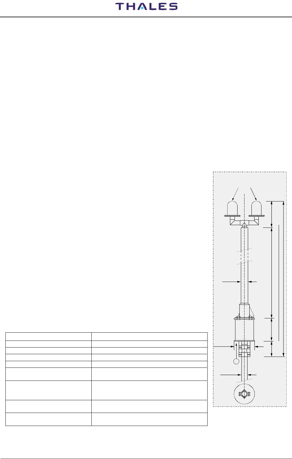
DME 415/435 -Technical Manual
Vol. 1-Section 4 - Technical Spec. 955 900 031 C
Vers. D, September 2005 THALES Italia S.p.A.- A. S. D. 4-17
• Dimensions:
- Height 262 mm (6HU front panel) – housing 220mm
- Width 106 mm (21 TU)
- Depth 285 mm included output connector
- Weight approx. 4,5 kg
• Protection class IP20
• Connectors (in/out) DIN 41612 H15
4.10 ANTENNA
4.10.1 Omnidirectional FAN 96 type
Mechanical Characteristics
• Weight 32 kg max.
• Dimensions See figure
• Protection Fiberglass tube
• Max. bearable wind speed 150 km/h with 12 mm of ice; safety
factor not < 2
• Wind pressure 40 kp max. (equal to 150 km/h with
12 mm of ice)
• Turn-over moment at base 70 mkp max.
• Environmental conditions:
- Temperature between -40 and +60 °C
- Humidity up to 100% with heavy rain not < 400
mm/Hg
• Obstruction lights Siemens 5NQ3208-0A type or
equivalent
Electrical Characteristics
• Frequency range 960 to 1215 MHz
• Polarization Vertical
• Input impedance 50 ohm, unbalanced
• V.S.W.R Less than 1.8 measured at the antenna input.
• Gain ≥ 9 dB referred to isotropic source
• Horizontal lobe
Circularity
Omnidirectional
≥ ±1.5 dB
• Vertical lobe
Lobe width of antenna
radiation in the plane
max. radiation at 4° (±1°) above horizon
≥ 6°
• Input RF Power 5 kWp, modulated and transmission cycle not
greater than 5 %
• Decoupling of the antenna
monitor probes 21,5±3 dB (flatness and stability: ±0.25 dB)
Obstructions light
~350
2200
300
200
220
60.5 max
90
A
3050
DME Antenna FAN 96
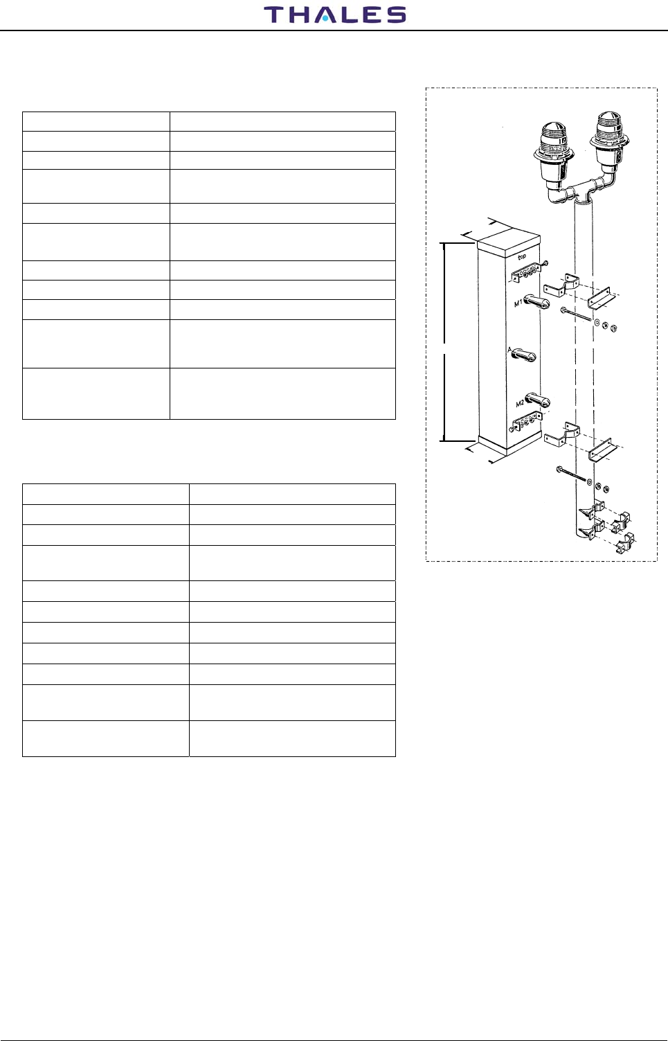
955 900 031 C
DME 415/435 -Technical Manual
Vol. 1-Section 4 - Technical Spec.
4-18 THALES Italia S.p.A.- A. S. D. Vers. D, September 2005
4.10.2 Sectorial FAN-88
Mechanical Characteristics
• Type FAN-88, directional antenna
• Net weight 12 kg
• Dimensions See figure
• Max exposed
area 0.38 m2
• Lateral thrust 60 kp at 160 km/h = 100 mph
• Wind velocity rated (1.65 safety factor)*/survival
(*based on the yield point)
• w/o ice 280 km/h / 360 km/h
• 1/2" radial ice 250 km/h / 330 km/h
• Packing 142 x 36 x 25 cm
• Temperature
range
(environment)
-30° to +60° C
• Lightning
protection
The antenna is DC grounded by a
cross-section of 640 mm2 hot dip
galvanized steel.
Electrical Characteristics
• Frequency range 960 – 1215 MHz
• Bandwidth 255 MHz
• V.S.W.R. <1.6 at antenna input
• Coupling attenuation 25 ±3 dB (antenna / monitor
probes)
• Beam tilt +4° ±0.5°
• RF peak power 10 kWp; duty cycle 2 %
• Polarization Vertical
• Horizontal lobe 66° (3 dB width, at mid band)
• Vertical lobe 13° (3 dB width, at mid band)
• Gain (ref. to half wave
dipole)
14 dB (in main lobe direction, at
mid band)
• Input (antenna and
monitor probes)
50 ohms; Type N female
connector
DME SECTORIAL ANTENNA FAN 88
1306
256
150

THALES Italia S.p.A.- Air Systems Division
Description, Installation, Operation, Maintenance Reference: Vol. 1 Code 955 900 031 C
GROUND BEACON
DME 415/435
Technical Manual
VOLUME 1
Equipment description, Installation, Operation, Maintenance and PC user
Vers. D, September 2005
SECTION 5
MAINTENANCE and
TROUBLESHOOTING

955 900 031 C DME 415/435 -Technical Manual
Vol. 1-Section 5 - Maintenance
5-II THALES Italia S.p.A.- A. S. D. Vers. D, September 2005

DME 415/435 -Technical Manual
Vol. 1-Section 5 - Maintenance 955 900 031 C
Vers. D, September 2005 THALES Italia S.p.A.- A. S. D. 5-a
Table of CONTENTS
Paragraph Page
SECTION 5............................................................................................................................................5-1
MAINTENANCE and TROUBLESHOOTING ......................................................................5-1
5.1 GENERAL.........................................................................................................................5-1
5.1.1 Standards and Tolerances................................................................................................5-2
5.1.2 Documentation of Flight Test............................................................................................5-2
5.2 MAINTENANCE................................................................................................................5-3
5.2.1 Periodic MAINTENANCE..................................................................................................5-3
5.2.2 Routine Tests....................................................................................................................5-3
5.2.3 Monitor Operation .............................................................................................................5-4
5.2.3.1 Single System Test...........................................................................................................5-4
5.2.3.2 Dual System Test..............................................................................................................5-4
5.2.1.1 Standby Operation Test....................................................................................................5-5
5.2.4 General Ordinary maintenance.........................................................................................5-6
5.2.4.1 Cleaning............................................................................................................................5-6
5.2.4.2 Other checks.....................................................................................................................5-6
5.2.4.3 Antenna Installation inspection.........................................................................................5-6
5.2.5 Maintenance operation procedures using external instruments.......................................5-7
5.2.5.1 Necessary tools and instruments......................................................................................5-7
5.2.5.2 Output Power measurement.............................................................................................5-7
5.2.5.2.1 On Dummy-Load procedure .............................................................................................5-7
5.2.5.2.2 On antenna procedure......................................................................................................5-8
5.2.5.3 Pulse shape, pulse spacing and Reply Delay ..................................................................5-9
5.2.5.4 Transponder Frequency Measurement ............................................................................5-10
5.2.5.5 Pulse Spectrum.................................................................................................................5-10
5.2.5.6 Transmission rate .............................................................................................................5-11
5.2.5.7 Monitor Interrogation - Pulse shape, pulse spacing and peak pulse level .......................5-11
5.2.5.8 Power Supply Measurements...........................................................................................5-12
5.2.5.9 Verification with Diagnostic Function................................................................................5-12
5.3 TROUBLESHOOTING......................................................................................................5-12
5.3.1 Useful Information for Troubleshooting.............................................................................5-13
5.3.1.1 Protection Devices............................................................................................................5-14
5.3.2 Troubleshooting Procedures.............................................................................................5-14
5.3.2.1 Diagnostics .......................................................................................................................5-14
5.3.2.1.1 Primary Voltages...............................................................................................................5-14
5.3.2.1.2 Stabilized Power Supplies ................................................................................................5-15
5.3.2.2 I/O System ........................................................................................................................5-15
5.3.3 Modules Replacement Procedures...................................................................................5-16
5.3.3.1 TX Module.........................................................................................................................5-18
5.3.3.2 TKW Module (DME435 only) ............................................................................................5-18
5.3.3.3 DPX Module......................................................................................................................5-18
5.3.3.4 MON and RX modules......................................................................................................5-18
5.3.3.5 Local Control status Unit - LCSU......................................................................................5-18
5.3.3.5.1 CSB Module......................................................................................................................5-18
5.3.3.5.1.1 Battery replacement..........................................................................................................5-19
5.3.3.5.2 INC Module.......................................................................................................................5-19
5.3.3.6 COAX Relay assembly .....................................................................................................5-19
5.3.3.7 I/O Panel ...........................................................................................................................5-19

955 900 031 C DME 415/435 -Technical Manual
Vol. 1-Section 5 - Maintenance
5-b THALES Italia S.p.A.- A. S. D. Vers. D, September 2005
Paragraph Page
5.3.3.8 AC/DC Module .................................................................................................................5-19
5.3.4 Peak power output Calibration Procedure .......................................................................5-20
5.3.4.1 DME 415 Program ACTIVATION.....................................................................................5-21
5.3.4.2 TX100 Modulation - adjust peak power output for DME 415 ........................................... 5-21
5.3.4.2.1 Meaning of the labels and data displayed (TX100)..........................................................5-22
5.3.4.2.2 Modification of reference parameters values ...................................................................5-22
5.3.4.3 Notation for the calibration of RF output power of the TX100.......................................... 5-24
5.3.4.4 Calibration of output RF signal for TX100........................................................................5-25
5.3.5 TKW 1KW Peak power output Calibration Procedure .....................................................5-26
5.3.5.1 DME 435 1KW Program ACTIVATION............................................................................ 5-26
5.3.5.2 TKW 1KW Modulation - adjust peak power output for DME 435.....................................5-26
5.3.5.2.1 Meaning of the labels and data displayed (TKW) ............................................................5-27
5.3.5.2.2 Modification of reference parameters values ...................................................................5-28
5.3.5.3 Notation for the calibration of RF output power of the TKW ............................................5-29
5.3.5.4 Calibration of output power RF for TKW ..........................................................................5-29
5.3.6 Reduced power - Check operation...................................................................................5-30
5.3.7 Adjustment Power Monitor Reading.................................................................................5-31
5.3.8 Test Points and Led .........................................................................................................5-32
5.3.9 Waveform .........................................................................................................................5-32

DME 415/435 -Technical Manual
Vol. 1-Section 5 - Maintenance 955 900 031 C
Vers. D, September 2005 THALES Italia S.p.A.- A. S. D. 5-c
List of FIGURES
Figure Page
Figure 5.1. a) Output Power test on antenna procedures - Test set-up (BIRD 4391) .......................5-8
Figure 5.1. b) Output Power test on antenna procedures - Test set-up (HP8900)............................5-9
Figure 5.2. LCSU - Lateral Side View of PBA's .............................................................................5-18
Figure 5.3. Test set-up...................................................................................................................5-20
Figure 5.4. References initial mask for alignment of 100W peak power output ............................5-21
Figure 5.5. References Mask with values for Mod Trx (example) .................................................5-21
Figure 5.6. Modify references values for Mod Trx (example) ........................................................5-23
Figure 5.7. Waveforms of detection for TX100..............................................................................5-24
Figure 5.8. Waveforms of modulation for TX100...........................................................................5-25
Figure 5.9. Incorrect Gaussian Pulses shape................................................................................5-25
Figure 5.10. References initial mask for alignment of 1KW peak power output..............................5-26
Figure 5.11. References mask with values for Mod Tkw (example)................................................5-27
Figure 5.12. Modify references values for Mod Tkw (example).......................................................5-28
Figure 5.13. Pulse shape for TX100 drive of TKW (example) .........................................................5-30
Figure 5.14. Setting Reduced power ...............................................................................................5-30
Figure 5.15. Screen of correct measurement by Monitor 1 & 2 (Example) .....................................5-31
Figure 5.16. Screen of configuration for power reading adjustment................................................5-31
Figure 5.17. PWS outline – Test point and LED..............................................................................5-32
Figure 5.18. MON outline – Test point and LED..............................................................................5-32
Figure 5.19. MON module – Waveform monitor: X mode Interrogation ..........................................5-33
Figure 5.20. MON module – Waveform monitor self-check: Attenuators check..............................5-34
Figure 5.21. MON module – Waveform monitor self-check: Y mode Interrogation.........................5-34
Figure 5.22. MON module – Waveform monitor self-check: CALIBRATION Delay ........................5-35
Figure 5.23. RX outline – Test point and LED .................................................................................5-35
Figure 5.24a. RX module – LOG N waveform Y mode......................................................................5-35
Figure 5.24b. RX module – LOG N waveform X mode......................................................................5-36
Figure 5.25. DPR outline – Test point and LED...............................................................................5-36
Figure 5.26 DPR module – Test point position...............................................................................5-37
Figure 5.27. DMD module – Waveform, X mode.............................................................................5-37
Figure 5.28. DMD outline – Test point and LED..............................................................................5-37
Figure 5.29. DMD module – Waveform, Y mode.............................................................................5-38
Figure 5.30. TX outline – Test point and LED..................................................................................5-38
Figure 5.31. TX module – Waveform – X mode .............................................................................5-39
Figure 5.32. TX module – Waveform – Y mode .............................................................................5-39
Figure 5.33. TKW module outline – Test point and LED .................................................................5-40
Figure 5.34. CSB Module – Test point position ...............................................................................5-41
Figure 5.35. ACDC module – Test points and LED outline .............................................................5-42
Figure 5.36a). DME 415 -Typical transmitted spectrum signal...........................................................5-43
Figure 5.36b). DME 435 -Typical transmitted spectrum signal...........................................................5-44

955 900 031 C DME 415/435 -Technical Manual
Vol. 1-Section 5 - Maintenance
5-d THALES Italia S.p.A.- A. S. D. Vers. D, September 2005
List of TABLES
Table Page
Table 5-1. Standards and Tolerances.......................................................................................... 5-2
Table 5-2. List of fuses .................................................................................................................5-14
Table 5-3. Procedures check during the modules replacement................................................... 5-17
Table 5-4 Tolerance of pulse envelope gaussian .......................................................................5-25
Table 5-5. Power Supply PWS module - External test points......................................................5-32
Table 5-6. Monitors MON module - External test points .............................................................. 5-32
Table 5-7. Receivers RX module - External test points ...............................................................5-35
Table 5-8. Digital Processor DPR module - External test points..................................................5-36
Table 5-9. Digital Modulator DMD module - External test points ................................................. 5-37
Table 5-10. Transmitter /driver TX module - External test points...................................................5-38
Table 5-11. RF 1KW Amplifier TKW module (only DME 435) - External test points......................5-40
Table 5-12. CSB Module Test Points.............................................................................................5-41
Table 5-13. AC/DC Module Test Points .........................................................................................5-42

DME 415/435 -Technical Manual
Vol. 1-Section 5 - Maintenance 955 900 031 C
Vers. D, September 2005 THALES Italia S.p.A.- A. S. D. 5-1
SECTION 5
MAINTENANCE and TROUBLESHOOTING
5.1 GENERAL
This section contains all data required for maintenance of the Model DME 415/435 - Distance-Measuring
Equipment - ground beacons. This section provides standards and tolerances, maintenance requirements,
required test equipment, performance check procedures, information supporting flight check of the station,
alignment and adjustment procedures, fault isolation, module replacement procedures, and technical
performance records for the DME ground station.
Maintenance on the DME beacons is made easier by using a personal computer (PC) based control and
monitoring system. This allows the operator to measure and control the main parameters of the DME
transponder using the PC keyboard and display.
This beacon does not require any particular maintenance operation. It has been conceived, from a
mechanical (plug-in system) as well as from an electrical point of view (use of mainly integrated, solid state
components) paying the greatest attention to the reliability factor. This intrinsic reliability is further enhanced
by the quality control method as per AQAP-1 requirements, as regards to production cycles, structure and
inspection; additionally, all automatically tested modules undergo "burn-in" procedures.
The DME 415/435 has been designed to minimize maintenance requirements using built-in computer
controlled test equipment and digital design techniques. Remote access to the equipment through the
modem interface allows the built-in test equipment (BITE) to be used to assure proper DME operation
without the need to visit the site.
The faulty modules may be detected following the information given in paragraph 5.3. Remove and replace
time is minimized by the use of plug-in assemblies that are easily accessed from the front of the cabinet.
Troubleshooting is made easier by the executive monitoring and test procedures, which perform real-time
Usually, operator, at the local site, does not control the beacon, although its operating conditions may be
checked through the messages displayed on the remote PC. The operator may also detect possible
parameter variations by displaying the information concerning the automatic monitoring cycle (EXECUTIVE
MONITORING), by performing the Routine Check, or by standard or specific measurements in manual tests
(Maintenance mode). Then comparing the results obtained to the previous data.
Faster on-site troubleshooting is possible using light-emitting diodes (LEDs) located on the modules. These
make it possible to detect a module failure by looking for an illuminated red LED on any card in the DME
card-cage. Another important instrument for troubleshooting is the DIAGNOSTIC function, which displays
the name of the faulty module. The diagnostic function is described in paragraph D.3.4.4 ANNEX D.
There are a few activities of normal maintenance, which should be performed in DME 415/435. All the main
parameters are maintained at the preset values throughout the entire life of the system by means of specific
circuits and a microprocessor controlled transponder, so that drift as a result of aging, will not occur. No
parts that are subject to mechanical wear are used. Since, the periodic maintenance intervals can be made
only whenever necessary and the number of measurements restricted to a minimum.
In addition, the radiated signals are checked by high-precision microprocessor controlled monitors. These
prevent faulty signals from being emitted by either switching over to the standby transmitter or shutting down
the system completely. Each monitor is a complete programmable DME instrumentation set in itself (BITE -
Built In Test Equipment), capable to perform all tests and checks required for routine maintenance and for
automatic diagnostics.
Preventive maintenance activities should be reduced in accordance with local regulations as actual data
proves that the requirements in ICAO 8071 are overly conservative.
Skilled operators and technicians may perform more, accurate measurements using external instruments.
The details about any of these measurements are given in the following paragraphs

955 900 031 C DME 415/435 -Technical Manual
Vol. 1-Section 5 - Maintenance
5-2 THALES Italia S.p.A.- A. S. D. Vers. D, September 2005
5.1.1 Standards and Tolerances
The main standards and tolerances for the 415/435 DME are listed in table 5-1.
Table 5-1. Standards and Tolerances
Parameter Lower
Limit Standard Upper
Limit Reference
Paragraph
Reply delay Standard minus
0.2 μs
Assigned at
commissioning Standard plus 0.2 μs 5.2.2
Reply coding Standard minus
0.1 μs
Assigned at
commissioning Standard plus 0.1 μs 5.2.2
Reply efficiency 66% 95% ... 5.2.2
Transmitter power -3.0 dB of standard Assigned at
commissioning ... 5.2.2
Radiated power -3.0 dB of standard Assigned at
commissioning ... 5.2.2
Transmitter pulse rate 80 pulse pairs per
second (pp/s)
below minimum
Assigned at
commissioning
800-2700 or 2700-
4800 pps
... 5.2.2
Transmitter pulse rise
time 1,5 μs 2,5 μs 3 μs 5.2.2
Transmitter pulse width 3 μs 3,5 μs 4 μs 5.2.2
Transmitter pulse
decay time 1,5 μs 2,5 μs 3,5 μs 5.2.2
Ident cycle time 25 s 30 s 40 s 5.2.2
Transmitter frequency - .001% Nominal channel
frequency +.001% 5.2.5.4
50 V supply low-power
transmitter (TX) 48 V 50 V 52 V 5.2.5.8
50 V supply high-power
amplifier (TKW) (435
only)
48 V 50V 52 V 5.2.5.8
Bus voltage 52 V 54V 55 V 5.2.5.8
5 V supply 4.75 V 5.00 V 5.25 V 5.2.5.8
15 V supply 14.25 V 15.00 V 15.75 V 5.2.5.8
-15 V supply -15.75 V -15.00 V -14.25 V 5.2.5.8
AC supply 187 VAC 230 VAC 276 VAC 5.2.5.8
5.1.2 Documentation of Flight Test
The data recorded during the flight test establishes the baseline for each DME installation. Documentation
is recorded by the printer connected to the PC or in a file on the PC (the Routine Check is the typical file
used). The data recorded during the commissioning and flight check should be recorded and stored in a
reference file. The same procedure should be followed when performing further checks, so the data
recorded can be compared with the original flight check data.

DME 415/435 -Technical Manual
Vol. 1-Section 5 - Maintenance 955 900 031 C
Vers. D, September 2005 THALES Italia S.p.A.- A. S. D. 5-3
5.2 MAINTENANCE
5.2.1 Periodic MAINTENANCE
The procedure is performed using the monitors BITE as measurement instruments.
Each parameter of the transponder in antenna is measured in real time by the monitor(s), which incorporate
a full measuring devices (BITE = Built In Test Equipment). These instruments are constantly verified by its
own self-check (integrity check of monitor) and the possible failure will be visualized through proper failure
messages and the faulty monitor will be switched off.
The frequency of this test might be reduced according to operator's requirements, to environmental
conditions and to the practical experience collected over time. Several customers suggest a periodicity of
once every two years.
Every parameter to be measured is associated with the corresponding limits according to Annex 10, Doc.
8071 Part III DME ICAO specifications, the standards and tolerances in para. 5.1.1, and manufacturer's in
technical specification data (section 4).
The BITEs are performed using a local or remote PC. General information is given in the following
paragraphs:
− the parameters measured with the EXECUTIVE MONITORING and ROUTINE CHECK programs may
also be measured using the CHECKS menu;
− in addition to the standard tests, the skilled operator may use the PRESETTABLE tests (ANCILLARY -
see ANNEX D section) to create special tests, not provided by the system, necessary to perform
particular checks
− before starting every ordinary maintenance procedure, it is necessary to analyze any possible alarm or
warning condition which may have occurred from the last maintenance intervention so as to perform
more accurate controls on the parameters showing signs of degradation;
− at the end of the maintenance procedures, print the last Routine Check and the data relating to every
measurement performed; compare them to the previous data and to the data obtained upon installation.
− these controls must be performed on both transponders and it is advisable to perform a final control on
the two of them using the diagnostic function (DIAGNOSTIC TEST).
Therefore, the equipment does not require typical scheduled maintenance. Only ordinary cleaning
maintenance is suggested.
For shelter, air conditioner and emergency battery (if applicable), observe, the manufacturers maintenance
recommendations. Battery type suggested: low maintenance or sealed type.
Additional external measurements are documented in paragraph 5.2.5. These allow the operator to test the
validity of the measuring devices inside the monitor by means of external instruments. These procedures
may be used at the discretion of the maintenance technician.
5.2.2 Routine Tests
Routine tests will verify the proper performance of the DME transponder and monitor. This performance test
should be run at discretion of operator. All limits should conform to the tolerances in table 5-1 or those
dictated by local regulations. All tests must pass.
If any tests fail, repeat the tests two or three times to verify the failure; then refer to paragraph 5.3 for
troubleshooting assistance.
a. For this procedure, data will be printed or saved to disk. If a printer is to be used it must be
connected. If the data is to be saved to a disk, use the save to a file option that is available when
the printer screen appears.

955 900 031 C DME 415/435 -Technical Manual
Vol. 1-Section 5 - Maintenance
5-4 THALES Italia S.p.A.- A. S. D. Vers. D, September 2005
b. Connect the PC to the DME. This may be done locally or remotely through telephone lines.
c. Log on.
d. Request control of the DME.
e. Select Checks and then "Executive monitoring on antenna" and "Monitor self check".
f. Select Abort to freeze the data.
g. Print the displayed data or save to a file. Exit screen.
h. Select Checks and then Routine check - Trx on Antenna. Wait for the tests to complete (tests will
take few minutes). When the “END ROUTINE CHECK” box appears, press RETURN or click on
OK. Review and confirm all data is within tolerances.
i. Print the displayed data or save to a file. Exit screen.
j. Select Checks and then Routine Check- On Monitor. Wait for the tests to complete (tests will take
several minutes). When the “END ROUTINE CHECK” box appears, press RETURN or click on
OK. Review and confirm all data is within tolerances.
k. Print the displayed data or save to a file. Exit screen.
The following may be done to document the setup of the equipment.
a. Select Settings and then Transponder Parameters.
b. Print the displayed data or save to a file. Exit screen.
c. Select Settings and then Operational Parameters.
d. Print the displayed data or save to a file. Exit screen.
e. Select Settings and then Monitor Thresholds.
f. Print the displayed data or save to a file. Exit screen.
g. Select Settings and then Restart delay.
h. Print the displayed data or save to a file. Exit screen.
i. Log off.
5.2.3 Monitor Operation
This test verifies that the monitor will alarm and that a transfer (dual system) or shutdown (single system)
will occur if a parameter is out of tolerance. This test will take the system off the air in automatic mode
operation.
5.2.3.1 Single System Test
a. Remove the monitor one coax. cable at the top of the cabinet. This will cause the transmission
rate and radiated power parameters to alarm.
b. Verify the system shuts down by looking at the front panel indications.
c. Verify there are no green LEDs illuminated on the transmitter assembly (TX). This confirms the
transmitter is off.
d. Replace the monitor one cable.
e. Restore the system to normal operation using the front panel.
5.2.3.2 Dual System Test
a. Remove the monitor one coax. cable at the top of the cabinet. This will cause the transmission
rate and radiated power parameters to alarm on monitor one.
b. Remove the monitor two coax. cable at the top of the cabinet.
c. Verify the system transfers to transponder 2 by looking at the front panel indications.
d. Verify there are no green LEDs illuminated on the transmitter one assembly (TX). This confirms
the transmitter is off.
e. Verify transponder two shuts down by looking at the front panel indications.
f. Verify there are not green LEDs illuminated on the transmitter two assembly (TX). This confirms
the transmitter is off.

DME 415/435 -Technical Manual
Vol. 1-Section 5 - Maintenance 955 900 031 C
Vers. D, September 2005 THALES Italia S.p.A.- A. S. D. 5-5
g. Replace the monitor one and two cables.
h. Restore the system to normal operation using the front panel.
5.2.1.1 Standby Operation Test
These procedures provide for checking the station batteries (if is not used the sealed type) and correcting
any deficiencies that may be found. These procedures should be performed to observing the periodic
maintenance of the manufacturers recommendations.
Batteries, generate an explosive gas under normal operating
conditions if is not used the sealed type.
Special care should be taken to avoid creating sparks that could ignite
this gas.
Ensure no tools or other metal objects can fall onto the batteries or
otherwise contact the batteries and cause a short.
Batteries contain a very corrosive electrolyte that can cause serious
injury to the skin and eyes.
Wear proper protective clothing and eye, hand, and face protection
when working with the batteries.
a. Visually inspect each battery and verify it is free of any bulges, cracks, or other deformations.
Replace any defective batteries.
b. Check all battery terminal connections and verify they are tight and free of corrosion.
c. Check that batteries are clean and free of corrosion. If necessary, remove dust or dirt by wiping
with a water moistened cloth. If battery electrolyte is present on the outer surfaces of the batteries,
neutralize it with a solution made up of 1/2-pound baking soda in 1 quart of water (0.22-kilograms
soda/liter water). Initially, this solution will bubble. The electrolyte is neutralized when bubbling no
longer occurs when fresh solution is applied. When electrolyte is neutralized, wipe battery clean
with a water moistened cloth. Dry battery with a dry clean cloth.
d. Using a digital multimeter or equivalent, measure voltage across all batteries. This voltage should
be approximately 54 volts DC. Record this voltage.
e. Divide the voltage recorded in step "d." by 4 and record this voltage.
f. Measure and record voltage across each battery. The voltage across each battery should be the
voltage recorded in step "e" ± 0.2 volt DC.
g. Turn off the AC power and record the time.
h. Five minutes after performing step "g", measure and record voltage across battery supply.
i. Twenty minutes after performing step "g", measure and record voltage across battery supply. This
voltage should be no less than 0.2 volt DC less than the voltage recorded in step "h". If battery
supply fails this check, measure and record voltage across each battery. If voltage across one
battery is 0.5 volt DC or more below voltage recorded in step "e", replace that battery. Charge the
battery and repeat steps "d" through "i". If the voltage across two or more batteries is 0.5 volt DC
or more below voltage recorded in step "e", charge battery supply and repeat steps "d" through "i".
j. Turn on the AC power.
WARNING

955 900 031 C DME 415/435 -Technical Manual
Vol. 1-Section 5 - Maintenance
5-6 THALES Italia S.p.A.- A. S. D. Vers. D, September 2005
5.2.4 General Ordinary maintenance
To avoid an electrical shock hazard, verify that the equipment is
powered down before attempting any general maintenance work.
5.2.4.1 Cleaning
Clean the outside and inside of shelter if necessary.
Clean the inside and outside of the equipment cabinet when become necessary.
Avoid transferring dirt on DME cabinet during the cleaning: use always a vacuum cleaner.
Cleaning aids, such as brushes and dusters, must be made of anti-static
material. Use only a soft cloth; do not use corrosive and abrasive
substances.
The local control and status unit (LCSU) front panel, may be damaged by
some types of chemicals used for cleaning. To remove layers of dirt on
the LCSU panel, use ethyl alcohol, glycol, or clean water. Moisten a cloth
with one of the liquids mentioned above and remove dirt.
Dusting of the subassemblies should only take place in conjunction with removal of a subassembly when
this becomes necessary. Even then, subassemblies should only be dusted if dust can be detected by
means of a visual check. They should always be dusted using a soft brush, and if possible with the aid of a
vacuum cleaner. During such operations, it is essential to observe all precautionary measures for voltage-
sensitive semiconductors.
5.2.4.2 Other checks
• Inspect all components to ensure that there is no damage, corrosion, or evidence of
overheating.
• Verify that all components are securely mounted.
• Verify that all electrical connections are secure.
5.2.4.3 Antenna Installation inspection
Inspect complete antenna mast installation, coax and connectors of antenna cables, line and obstruction
lights for any damage caused by corrosion, rodents, termites, or others. The periodicity of inspections
depends of environmental conditions of the site.
Tight fitting of all RF cable connections (internal and external)
CAUTION
WARNING

DME 415/435 -Technical Manual
Vol. 1-Section 5 - Maintenance 955 900 031 C
Vers. D, September 2005 THALES Italia S.p.A.- A. S. D. 5-7
5.2.5 Maintenance operation procedures using external instruments
This paragraph gives a simple and concise description of the main procedure, which may be performed by
operators and skilled technicians using the external additional measurement instrumentation on site.
These paragraphs describe procedures to externally verify some of the important measurements made
using test equipment built in to the DME. These procedures are normally not required but can be used at
the discretion of the maintenance technician.
NOTE: If during maintenance operations it is necessary to stop the irradiated signal, the responsible
authorities (e.g. ATC/Controls) must be informed before commencing any maintenance work in
accordance with national regulations.
5.2.5.1 Necessary tools and instruments
This is a list of test equipment required for site level maintenance on the DME. Equivalent test equipment
may be used. Common tools such, as screwdrivers, pliers, and wrenches. A 5/16-inch, 5-inch-pound
torque wrench is recommended for tightening the SMA cable connector nuts.
In addition to the material supplied with the beacon (tool kit and extender board), the following measuring
instruments are required:
- Personal Computer, if missing at local site (Lap/palm top or STD PC), cables connection, startup disk,
printer, adapter connectors
- Oscilloscope dual/four vertical channels ,100 MHz BW, type (Tek 2235A or PM3050)
- Multimeter (input 1 MΩ impedance )
- Peak Power METER (HP 8900) with probe 1 W f.s. and a series of precision attenuators (± 0,1 dB) 10
dB/5W, 20dB/1W, 30dB/1W (or directional coupler)
or kit: BIRD wattmeter (digital RF mod 4391 with elements: 1000J,250J,100j,25J)
- Timer-Counter up to 2 GHz (Hp 5315A-H10-003, Tek CMC251)
- Spectrum Analyzer up to 2 GHz (if necessary: see note in para 5.2.5.5.)
5.2.5.2 Output Power measurement
The detailed procedure of alignment and checking of the TX100 and TKW modules RF output power are
described to paragraph 5.3.4 with a specific "DME400 E2prom TX/TKW" program
5.2.5.2.1 On Dummy-Load procedure
NOTE: This test will take the system no stop during the test
a) Perform the EXECUTIVE MONITORING or Routine Check at Peak Power Output measurement on TRX
in Dummy Load (Maintenance Environment)
b) Verify and record the peak power value
c) Switch OFF the TRX on dummy load and take the place of the 50 Ω dummy load by the probe of the
wattmeter, via 30dB precision attenuator (DME415) or 40dB precision attenuator (DME435).
Do not set the beacon to OPERATING when the antenna or
dummy load is not connected.
d) Set the beacon to operating and read the value by the instrument
e) Verify that the value read is equal to the value recorded by internal monitor (s) (±10%)
f) At the end of the measurements, take note of the values concerning both transponders and restore the
initial connections
CAUTION
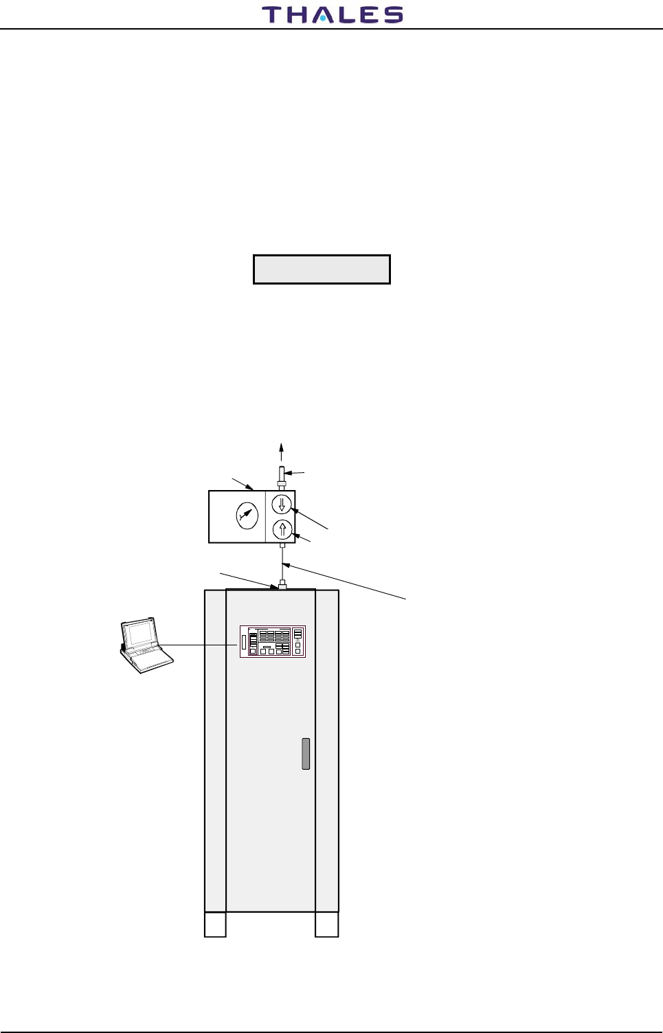
955 900 031 C DME 415/435 -Technical Manual
Vol. 1-Section 5 - Maintenance
5-8 THALES Italia S.p.A.- A. S. D. Vers. D, September 2005
5.2.5.2.2 On antenna procedure
NOTE: This test will take the system off the air during the connection of the instruments
a) Connect test equipment as shown in figure 5.1. a) for the type of power meter that will be used, for the
Bird-type peak power meter set up and figure 5.1. b) for the HP-type peak power meter set up.
b) Perform the EXECUTIVE MONITORING or Routine Check at Peak Power Output measurement on
TRX (Maintenance Environment)
c) Verify and record the peak power value
d) Switch OFF the beacon.
Do not set the beacon to OPERATING when the antenna or dummy
load is not connected.
e) Set the transponder to be measured to operating and read the value by the instrument
f) Verify that the value read is equal to the value recorded by internal monitor (s) (±20%)
g) At the end of the measurements, take note of the values concerning both transponders and restore the
initial connections.
DME 415/435
Cable assembly, RF, 30 cm
RG214 - N male
PEAK POWER
METER
(BIRD Model 4391 type)
to ANTENNA
Heliax
1/2" cable
Use with TWO Plug-In ELEMENTS
as appropriate:
FORWARD HIGH Power - 1000J
REVERSE LOW Power - 100J
FORWARD LOW Power - 250J
REVERSE LOW Power - 25J
Antenna connector
Plug-in
ELEMENTS
Figure 5.1. a) Output Power test on antenna procedures - Test set-up (BIRD 4391)
CAUTION
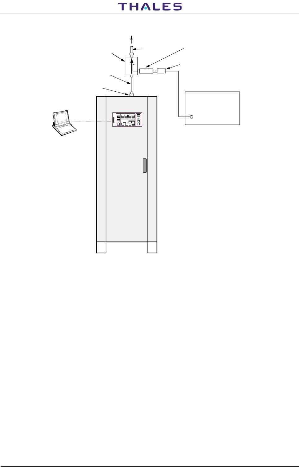
DME 415/435 -Technical Manual
Vol. 1-Section 5 - Maintenance 955 900 031 C
Vers. D, September 2005 THALES Italia S.p.A.- A. S. D. 5-9
DME 415/435
Cable assembly, RF, 30 cm
RG214 - N male
20 dB Directional Coupler
PEAK POWER
METER
(HP 8900)
to ANTENNA
Heliax
1/2" cable
Combined attenuation
directional coupler-Attenuator
shall be 60 dB for 1 KWp
and 50db for 100Wp
Power meter
PROBE
Antenna connector
Figure 5.1. b) Output Power test on antenna procedures - Test set-up (HP8900)
5.2.5.3 Pulse shape, pulse spacing and Reply Delay
This procedure allows the operator to measure the pulse shape and pulse spacing of the transmitter output.
The operator can also measure the system reply delay. The procedure uses a dual channel oscilloscope.
This method is not as accurate as the technique used in the monitor. The results obtained using the scope
will typically be with ±5 percent of the readings displayed by the monitor.
Oscilloscope connections:
• Channel one is connected to monitor test point AN34. See figure 5.23
• Channel two is connected to transmitter test point AN7 (TX100-DME 415) or "AN 7 RF detected" (TKW
- DME 435). See figure: 5.30 (DME 415), 5.33 (DME 435)
• The external trigger input of the oscilloscope is connected to monitor test point AN2 (or AN72). See
figure 5.16.
• Adjust the time base and trigger to allow the interrogations on channel one and the replies on channel
two to be displayed on the screen.
a. Rise Time. Examine the pulses on channel two of the oscilloscope. Set the oscilloscope time
base to 1 or 2 μs. To measure the rise time, measure the time for the leading edge of the pulse to
transition from 10 percent of its peak value to 90 percent of its peak value. Record this time.
b. Duration. Examine the pulses on channel two of the oscilloscope. Set the oscilloscope time base
to 1 or 2 μs. To measure the duration, measure the time between the 50 percent point of a pulse
rise time and the 50 percent point of the pulse fall time. Record this time.

955 900 031 C DME 415/435 -Technical Manual
Vol. 1-Section 5 - Maintenance
5-10 THALES Italia S.p.A.- A. S. D. Vers. D, September 2005
c. Decay Time. Examine the pulses on channel two of the oscilloscope. Set the oscilloscope time
base to 1 or 2 μs. To measure the fall time, measure the time for the trailing edge of the pulse to
transition from 90 percent of its peak value to 10 percent of its peak value. Record this time.
d. Pulse Spacing. Examine a pulse pair on channel two of the oscilloscope. To measure accurately
the pulse spacing, measure the time between the 50 percent point of the pulse rise time of the first
pulse and the 50 percent point of the pulse rise time of the second pulse. Record this time.
e. Verify that the values read on the scope are equal (± 2 percent) to the values measured by
monitors (on test of executive monitoring or routine check).
f. Reply Delay. Channel one shows the interrogation pulses. Channel 2 shows the transmitter
pulses. Set the oscilloscope time base to 10 μs. Measure, accurately, the time from the 50
percent point of the leading edge of the first constituent pulse of the first pulse pair on channel
one, to the 50 percent point of the leading edge of the first constituent pulse of the first pulse pair
on channel two.
Other method of measure, of the replay delay, is that shown in figure 5.19.
g. Verify that the values read on scope are equal (± 1 percent) to the values measured by monitors
(on test of executive monitoring or routine check).
5.2.5.4 Transponder Frequency Measurement
This procedure measures the DME transponder frequency. The frequency source used by the transmitter
and receiver is located in the receiver module.
a. Connect PC to DME front panel RS-232 connector.
b. Log on. Use Commands to turn beacon one off.
c. Remove the low-power transmitter module (TX). The module may be removed with power on.
d. Connect frequency counter to the upper RF connector that interfaces with the removed transmitter
assembly. Use the BNC female to backplane female adapter to convert the top connector to a
BNC female connector. This will allow a cable with BNC male connectors on both ends to be used
with the frequency counter.
e. Frequency counter should indicate station assigned carrier frequency ±0.001 percent.
f. Disconnect adapter, cable, and frequency counter.
g. Replace transmitter.
h. For a dual system, use Commands to turn beacon two off. Repeat steps c through g with the
second transmitter.
i. Replace the transmitter(s). Restore the system to normal operation.
j. Log off.
5.2.5.5 Pulse Spectrum
NOTE
This procedure is significant for sites where beacons or other radio
equipment are installed within a radius of 5 NM (Nautical Miles) and
have adjacent channel frequencies. Therefore, it is not necessary if
these conditions are not present.

DME 415/435 -Technical Manual
Vol. 1-Section 5 - Maintenance 955 900 031 C
Vers. D, September 2005 THALES Italia S.p.A.- A. S. D. 5-11
Procedure:
a. Using a 40 dB attenuator for DME 435 and 30 dB for DME 415, connect the spectrum analyzer to the
coaxial cable, coming from one of the two antenna probes. First, disconnect the cable from its
connector on top of the equipment cabinet.
b. Use a 30 to 100 kHz/div band width and select the beacon frequency for the spectrum analyzer.
Position the spectrum lines on the raster center of the instrument display and adjust the signal peak
level so that it touches the first top line of the raster.
c. Verify that with FREQUENCY SPAN equal to 0.5 MHz/div, all the spectrum lines at a frequency
greater than the beacon frequency ±2 MHz are attenuated of at least 65 dB for DME 435 and 58 dB
for DME 415 with respect to the beacon frequency peak level, at raster center.
d. Verify that with FREQUENCY SPAN equal to 0.2 MHz/div, all the spectrum lines at a frequency
greater than the beacon frequency ±0.8 MHz are attenuated of at least 47 dB for DME 435 and 40 dB
for DME 415 with respect to the beacon frequency peak level, at raster center.
e. At the end of the measurements, take note of the values concerning both transponders and restore
the initial connections.
5.2.5.6 Transmission rate
a) Perform the executive monitoring cycle and/or the Routine Check and/or TRANSMISSION RATE
manual test.
b) Verify that the obtained value comes within the limits indicated.
c) Connect the frequency counter to AN7 test points of transmitter TX module. See figure 5.30.
d) Set the counter to read the frequency values in the low frequency range (<100 kHz and high input
impedance) and to count the pulses. Because of the random nature of DME output pulses, the
frequency counter will not display a constant value. The reading will be affected by aircraft
interrogations. Do not use a value measured during a DME identification period. The counter
reading will increase during the DME identification period. Divide the frequency counter reading by
two to obtain the frequency of pulse pairs (as read by the monitor).
e) Read the value given by the instrument and verify the reading (divided by two) is within the indicated
tolerance limits.
NOTE
The actual ppps number depends on the transmission rate selected
and on the number of interrogating aircraft at the instant the
measurement is made.
5.2.5.7 Monitor Interrogation - Pulse shape, pulse spacing and peak pulse level
The external trigger input of the oscilloscope is connected to monitor test point AN2. See figure 5.16
Connect the probes of oscilloscope on test point AN34 "Out MUX" of the MON module and record:
− Rise time
− Duration
− Decay time
− Pulse spacing
− Peak pulse level
Verify that the values read on scope are equal (± 2%) to the values measured by monitors (on test of
executive monitoring or routine check)

955 900 031 C DME 415/435 -Technical Manual
Vol. 1-Section 5 - Maintenance
5-12 THALES Italia S.p.A.- A. S. D. Vers. D, September 2005
5.2.5.8 Power Supply Measurements
This test measures the key power supply voltages in the 415 DME.
a. Measure the +5 volt (nominal value: 5,1V), +15 volt, and –15 volt levels using the test points on the
PWS module. See figure 5.17 for the test points location. See table 5-1 for tolerances. For a dual
system, perform measurement on both PWS modules.
b. Measure the AC input voltage. The voltage should be measured at the terminal where AC power
comes into the cabinet.
Dangerous voltage (240 V AC) exists within the DME system (only on
subrack BCPS unit). Contact with this voltage can cause personnel
injury or death.
c. Measure the DC bus voltage. This can be done at the top, left (front) corner of each transponder
card cage backplane. This point is labeled +48. The point to be measured has a red wire. Chassis
ground can be used as a reference.
The DC bus voltage can also be measured using the + and – test points on the AC/DC module.
See figure 5.35.
d. Measure the output of the DC/DC converter on the low-power transmitter module (TX). See figure
5.30 (AN 17) for the test point location. See table 5-1 for tolerances. For a dual system, perform
measurement on both TX modules.
e. Measure the output of the DC/DC converter on the 1000 watt transmitter module (TKW). See figure
5.33 (AN 1 DC/DC Out) for the test point location. See table 5-1 for tolerances. For a dual system,
perform measurement on both TKW modules.
5.2.5.9 Verification with Diagnostic Function
The Diagnostic is the last operation to be performed and is used to check both transponders.
If this verification and previous inspections and controls confirm the good beacon operating conditions, all
beacon mechanical and electrical components as well as its software can operate correctly. With regard to
the software, it should be noticed that most of its functions have been enabled during the measurements.
To run the Diagnostic software, place the DME in maintenance. Select the Diagnostic test from the Checks
menu. See Annex D for more information.
5.3 TROUBLESHOOTING
This paragraph contains only the information necessary to detect and replace faulty modules, which should
then be repaired at an authorized repair facility.
Troubleshooting is made easier thanks to the built-in testing available in the 415/435 DME.
By looking at the failure messages displayed on the PC video, the operator may easily detect any beacon
malfunction; these messages make it possible to detect the malfunctioning module, if any, and to take the
necessary organization and urgency measures (primary or secondary alarm) so as to repair the module at
the local site. Considering the functional services offered by the beacon, when both transponders are shut
down, it is advisable to first restore one of the two transponders using the redundant and operating modules
of the other one.
WARNING

DME 415/435 -Technical Manual
Vol. 1-Section 5 - Maintenance 955 900 031 C
Vers. D, September 2005 THALES Italia S.p.A.- A. S. D. 5-13
The technicians involved in troubleshooting should have a good knowledge of 415/435 theory of operation.
The technician must be familiar with safety measures required to prevent injury to maintenance personnel
and damage to the beacon.
Replace the modules in the sequence indicated by the diagnostics; before every replacement, display all
possible stored alarms or warnings occurred from the last maintenance intervention.
According to the color, the warning lights on the different modules will have the following meanings:
− Green light: normally on, it indicates that the module or circuit being controlled is operating.
− Red light: normally off, it comes on in case of failure of the module.
− Yellow light: normally on, it provides further indications (secondary or partial) about beacon operation.
The same color method is used for the messages displayed on the video: these messages may be seen
only if a color video is used. The WARNINGS, ALARM, SHUT-DOWN and HARD (primary alarm presence
indication) messages are red and flashing so as to be easily seen even on a monochromatic video.
When the beacon is in good operating conditions, no red LED should be on and no red message should
appear on the PC video.
Before replacing a module with a red LED on, it is advisable to reset the module or the beacon since a
transient malfunction might have caused a protection to be activated and therefore the LED to be lit. The
reset pushbutton on the DMD or MON modules can not be used if an initialization is being performed.
Connections made with flat and coaxial cables and to passive, non-plug-in components offer a high
reliability level; they, however, should not be overlooked, but may be checked in conclusion.
Proceed with great care when it is necessary to work on BCPS unit
rear part since a 220 Vac dangerous voltage is present.
Radio frequency voltage on RF power amplifier modules output
represent a personnel hazard.
Inside AC/DC modules there are the 220 Vac mains voltage and the
corresponding 300 Vdc rectified voltage whose capacitors may remain
loaded for several seconds after the modules are disconnected. After
removing the modules wait for a few minutes before touching the
internal circuits.
RF loads (antenna cable, 50 Ω loads) should always be connected
when the transponder is set to OPERATING to prevent the RF
components from being damaged.
5.3.1 Useful Information for Troubleshooting
The procedures for the remote site are true for the local site as well, but not vice versa. The remote site is a
center or a control site situated far away from the place where the beacon is installed. The local site is the
place, near the antenna, where the beacon is installed. The two sites may be a few meters or many
kilometers apart.
Remember that the modules should be replaced when the beacon is off/stby condition.
For repairing operations at local site, the following items are required:
− tool kit and spare fuses, supplied with the beacon;
CAUTION
WARNING

955 900 031 C DME 415/435 -Technical Manual
Vol. 1-Section 5 - Maintenance
5-14 THALES Italia S.p.A.- A. S. D. Vers. D, September 2005
− digital voltmeter;
− spare modules, especially those which are not redundant on the beacon such as LCSU, AFI ;
− IBM compatible Personal Computer (Lap/Palm top) provided with video, keyboard, 3.5" and CDROM disk
drive, cable for connection to the beacon, printer and startup programs disk.
5.3.1.1 Protection Devices
Fuses are employed to protect the BCPS unit and the PWS, TX and TKW (DME435 only) modules; their
features are listed in table 5-2.
Table 5-2. List of fuses
Module TYPE OF FUSE Q.TY NOTE
BCPS/pcs 10 A type T (6.3 x 32)
2 A type T (6,3 x 32)
2
1
Placed on terminal boards of the transponders
48 Vdc power supply line.
They are located on the terminal board
BCPS/Frako 10A type T (6.3 x 32)
2 A type T (6,3 x 32) 2
2 Inline Fuse-holders
PWS 6 A type T (5 x 20) 1 48 Vdc line - Placed on PBA of PWS module
TX 3A solder type 1 48 Vdc line - Placed on PBA of TX module
TKW 6A solder type 1 48 Vdc line - Placed on PBA of TKW module
5.3.2 Troubleshooting Procedures
5.3.2.1 Diagnostics
The diagnostics can be run, upon command from the operator (remote or local site), either in automatic
mode or in manual mode to check the efficiency of the transponder connected to the dummy load by
carrying out a sequence of tests. Since both monitors are used for the tests, these monitors and the power
supply modules are checked before all the other modules. Any possible faults are indicated with appropriate
error messages displayed on the video of the PC from which the diagnostics has been activated.
5.3.2.1.1 Primary Voltages
The local or remote operator may obtain only the information relating to the site, where the equipment is
standing. Remember what follows:
The type of power provided to the beacon is clearly indicated on the PC video (POWER:MAINS and
POWER:BATT. messages).
If the mains power fails the beacon will be switched to battery power supply and its operation will not be
interrupted: the POWER:BATT. message will appear on the video.
A protracted mains failure may lead to battery depletion and to a resulting interruption of beacon
operation. 50 A/h batteries standard autonomy is approx. 8 hours; it is therefore advisable to check the
external electrical panel breaker should the mains failure protracts for more than 4 hours.
If both mains and battery power supplies fail, the PC video will be in initialization request message by the
equipment displayed on the PC video.

DME 415/435 -Technical Manual
Vol. 1-Section 5 - Maintenance 955 900 031 C
Vers. D, September 2005 THALES Italia S.p.A.- A. S. D. 5-15
5.3.2.1.2 Stabilized Power Supplies
The operator may obtain only the information relating to the site, local or remote, where he is standing.
Remote Site
A faulty AC/DC module in the BCPS unit is indicated by the relevant warning message AC/DC FAULTY,
on PC monitor .The POWER:BATT. message may be visualized if there is no power from the mains, or
also if both AC/DC modules are faulty.
Before removing the housing of AC/DC module waiting for about 1
minute after shoot-down the supply and removing the line connections
Failure of the PWS, TX, TKW modules is indicated by message of warning and may be visualized the
value of regulate voltages.
Local Site
A faulty AC/DC module in the BCPS unit may be detected through the green LED on the front of the
module.
The faulty PWS module may be detected by the corresponding green LED off. In this case, proceed as
follows: reset the module by pushing the appropriate pushbutton, check and if necessary replace the
module fuse and, if the malfunction can not be eliminated, replace the module.
The correct operation of the TX and TKW (DME435 only) module DC/DC converters is indicated by the
corresponding green LEDs, which should be on if the corresponding transponder, is set to OPERATING.
5.3.2.2 I/O System
The parts of the I/O system that could result faulty are listed below, starting with the most probable:
− CSB module in the LCSU unit;
− INC module in the LCSU unit;
− I/O panel (connectors on top of the cabinet);
− interconnecting cables and connectors.
Diagnostics is essentially based on checking the indications provided by the front panel of INC module.
Some of the more common cases are described below.
a. No indication or command possible
Probably a power failure: check the voltage (+5V) of CSB module. If the measured value is +5V
± 5%, the fault is probably on the CSB or INC board, or the connection cable.
b. Green OPERATION indicator in LCSU section switches off.
Probable hardware or software fault on CSB board; this condition is also caused by <4.7 V power
supplies.
c. Yellow WARNING indicator switches on in LCSU section.
A hardware fault in RTC (Real Time Clock) circuit on CSB board.
d. Red DATA COM indicator switches on in MAIN STATUS section.
Indicates no communication between LCSU unit and the equipment modules. This condition may be
caused by faults in the serial port circuit on CSB board, or the interconnecting cables and
connectors.
WARNING

955 900 031 C DME 415/435 -Technical Manual
Vol. 1-Section 5 - Maintenance
5-16 THALES Italia S.p.A.- A. S. D. Vers. D, September 2005
Before replacing the CSB board, make these two tests:
a. Press the LAMP TEST pushbutton located in the LCSU section and verify the indicators are working
properly.
b. Shut down all the equipment from the control panel then switches on again after a few seconds.
If the fault persists, replace the CSB board since the failure is not caused by a transient fault condition.
The INC board can be indirectly tested through the LAMP TEST. By verifying that the individual indicators
and buzzers are operating and using the control push-buttons, check they are working efficiently.
If the indications and commands are correct on the PC and the corresponding indications are different on
the INC module, there may be an INC board fault or the configuration made is not correct.
The serial and parallel ports I/O can be checked by verifying the ON/OFF levels using the Hardware Test
described in section 3 in this volume; item [3] of the main menu displays the HARDWARE TEST command
that can be used to test all the parallel line inputs and outputs and all the serial channels either separately or
in groups.
Cable or connector faults are unlikely to occur. When they are present, a visual inspection will often indicate
where a cable has been damaged.
5.3.3 Modules Replacement Procedures
a) All the modules may be removed and installed without removing power. The special design of the
connector that supplies power to each module prevents damage to the electronics from occurring.
b) Modules replacement is made easier thanks to the plug-in technique and to the upper and lower
extractors every module. To extract these modules, lift the extractors (push them towards the inside of
the beacon) and pull the module out of its guides. To reconnect the module, reinsert it back in its guides,
push it in and lower the extractors.
c) Several of the modules have jumper switches on their printed circuit boards. It is essential to check that
the switches or jumpers on the new PBA are set to the same positions as on the old module. Section 2
"INSTALLATION" contains the list of the jumpers.
d) Modules with extractors do not require any special operations for their replacement, except for the DPX
and TKW modules, which requires unscrewing the proper front screws and coax. cables disconnection.
e) Outline drawing are shown in this section
f) For other modules, not proved with extractors and requiring particular procedures, proceed as described
below.
g) The specific RF connectors plug-in, situate at the back panel and associated to semi-rigid coax cables,
must be fixed in sure way from the proper nut, by using the spanner of 16 mm. They must have little end
clearance to help the insertion system. On each removed module, to check and regulate manually that
each RF connector on the back panel are under the previously mentioned conditions. The modules
interested at these notes are RX, MON, DPX, TX100 and TKW.
Connectors SMA must be fixed with the torque wrench (1Nm/8.9in-lbs) code 870952302X. You have this
spanner in the tool bag of the equipment.
Connectors "N" of coax cables, must be screwed and blocked in sure way.
NOTES: Check that all the RF cables have been connected correctly before switching the transmitter on
again, and make sure that either the antenna or a dummy load is connected
On some modules are scheduled opportune trimmers that are factory adjusted: they must not be
tampered with, if the maximum precision of system wants to be obtained.
After having replaced the TX100 or/and TKW module it is essential to follow the described
procedures to paragraphs 5.3.5 and 5.3.4 for the respective channel of operation

DME 415/435 -Technical Manual
Vol. 1-Section 5 - Maintenance 955 900 031 C
Vers. D, September 2005 THALES Italia S.p.A.- A. S. D. 5-17
The following table shows the procedures for to obtain the better performance during the modules
replacement
Table 5-3. Procedures check during the modules replacement
Module LED and
TP Trimmer Procedures check
MON Fig. 5.18
Tab. 5-6 P6 To adjust trimmer P6 as para 2.6.4.2.2 "Measurement calibration of the
TRANSMITTED POWER (radiated)" of the section 2 - Installation
On PC to verifier, the parameters from menu CHECK: "Routine check -
on monitors" and "monitor self check".
Parameters measures must not exceed given limits.
PWS Fig. 5.17
Tab. 5-5 - Repeat the check as to para. 5.2.5.8
RX Fig. 5.23
Tab. 5-5
- On PC, to verifier the parameters from menu CHECKS: "Executive
Monitoring" e/o "Routine check" - TRX on Antenna.
Especially verify the following parameters: Transmission frequency,
Adjacent channel rejection, Echo suppression, Reply efficiency, Reply
delay, sensitivity, dead time, Identity Code.
Parameters measures must not exceed given limits.
TX Fig. 5.23
Tab. 5-7 P3 Fine adjust RF power level for calibration of RF Power out (factory
adjusted)
Repeat the check as to para. 5.2.5.8 for the power supply regulated
voltages
On PC, to verifier the parameters from menu CHECKS: "Executive
Monitoring" e/o "Routine check" - TRX on Antenna.
Especially verify the following parameters: Peak power Out, Pulse shape,
Pulse spacing, Transmitter frequency, Transmitter power, Transmission
rate, Reply delay, Identity code.
Parameters measures must not exceed given limits.
TKW Fig. 5.33
Tab. 5-11
Repeat the check as to para. 5.2.5.8 for the power supply regulated
voltages
On PC, to verifier the parameters from menu CHECKS: "Executive
Monitoring" e/o "Routine check" - TRX on Antenna.
Especially verify the following parameters: Peak power Out, Pulse shape,
Pulse spacing, Transmitter frequency, Transmitter power, Transmission
rate, Reply delay, Identity code.
Parameters measures must not exceed given limits.
DPX - On PC, to verifier the parameters from menu CHECKS: "Executive
Monitoring" e/o "Routine check" - TRX on Antenna.
Parameters measures must not exceed given limits.
DPR Fig. 5.25
Tab. 5-8
On PC, to verifier the parameters from menu CHECKS: "Executive
Monitoring" e/o "Routine check" - TRX on Antenna
Parameters measures must not exceed given limits.
DMD Fig. 5.28
Tab. 5-9
On PC, to verifier the parameters from menu CHECKS: "Executive
Monitoring" e/o "Routine check" - TRX on Antenna
Parameters measures must not exceed given limits.
AC/DC Fig. 5.35
Tab. 5-13
Repeat the check as to para. 5.2.5.8 for the 54V power supply
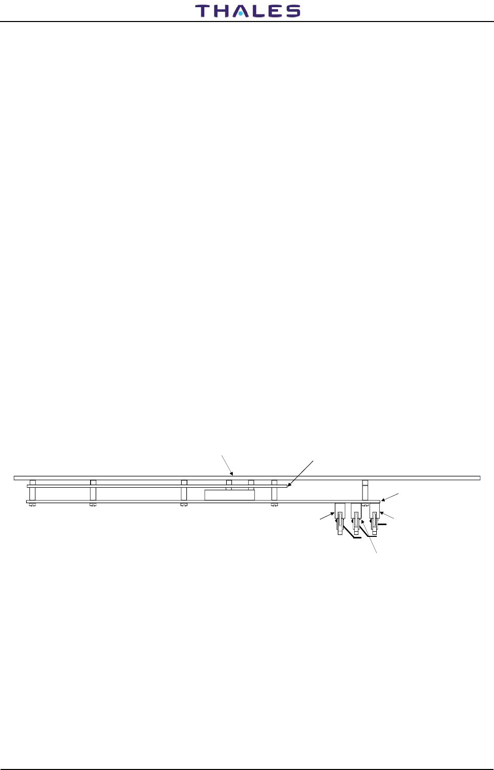
955 900 031 C DME 415/435 -Technical Manual
Vol. 1-Section 5 - Maintenance
5-18 THALES Italia S.p.A.- A. S. D. Vers. D, September 2005
To replace, proceed as follows:
5.3.3.1 TX Module
NOTE: After having replaced the TX 100 or/and TKW module it is essential to follow the described
procedures to paragraphs 5.3.4 and 5.3.5 for the respective channel of operation
Extract or insert it when the transponder is not set to OPERATING.
Note: During the correct insertion of the modules, to follow the paragraph 5.3.3 g) explanation
5.3.3.2 TKW Module (DME435 only)
NOTE: After having replaced the TX100 or/and TKW module it is essential to follow the described
procedures to paragraphs 5.3.5 and 5.3.4 for the respective channel of operation
Make sure the transponder to which the module is associated is off/stby, then proceed as follows:
a) disconnect the coax cables of the two RF OUT of TKW module and RF IN of DPX module
connectors;
b) loosen the four screws (two on each up and lower side);
c) remove the module by means of two handles knobs.
Note: During the correct insertion of the modules, to follow the paragraph 5.3.3 g) explanation
5.3.3.3 DPX Module
a) disconnect the coax cables of the two RF OUT and RF IN connectors
b) loosen the four screws (two on each up and lower side);
c) remove the module
Note: During the correct insertion of the modules, to follow the paragraph 5.3.3 g) explanation
5.3.3.4 MON and RX modules
Note: During the correct insertion of the modules, to follow the paragraph 5.3.3 g) explanation
5.3.3.5 Local Control status Unit - LCSU
The modules are fastened with screws and screw-threaded supports. The INC board, fastened on the front
metallic plate, supports the CSB board (figure 5.2)
CSB Module
INC Module
M32
M53
M22
Front panel
Figure 5.2. LCSU - Lateral Side View of PBA's
5.3.3.5.1 CSB Module
From the back of the beacon front door, remove the cable connectors relating to CSB board
NOTE
The M18 power supply connector must always be removed first and inserted last.
The modules must be extracted or inserted keeping them parallel to the front panel
(to avoid connector pins warping)
After replacement of the CSB board, the I/O system has to be reconfigured.
Loosen the ten printed circuit screws; remember that M21/M17 plug-in connector from CSB module is
used for the signal and power supply connections between the CSB and INC modules.

DME 415/435 -Technical Manual
Vol. 1-Section 5 - Maintenance 955 900 031 C
Vers. D, September 2005 THALES Italia S.p.A.- A. S. D. 5-19
5.3.3.5.1.1 Battery replacement
To back up data in the non-volatile random-access memory (RAM) in case of a voltage drop, the
subassemblies LCSU/CSB contain NI_CD batteries. The battery voltage is checked by the BITE of the
system. The individual batteries are soldered to the PCB. The battery back up function is enabled via
jumpers (M1 of Figure 2.19 section 2)set during first setup or before replacing the respective PCB. Contents
of the RAM will be lost when the jumper is opened which enables battery voltage to the RAM device. Always
observe the label on the battery. The battery has to be replaced by the same battery type.
The presence of dirt or moisture on the board can increase the battery current consumption and decrease
the battery life. It’s also necessary to check that the solder side of the board does not contact the conductive
plane, in order to avoid short-circuits or excessive current consumption.
If replacement of the battery is necessary, attention must be paid to the correct polarity as well as the
electrical characteristics of the new battery (see CSB board layout - component ref.: BAT1).
Replace the battery when the voltage is < 3Vdc, reading on proper terminals without the 5V power supply on
the card.
A soldering iron with a grounded soldering tip should be used.
Remove M1 jumper during the battery replacement
Re-tin the soldering tags of the new battery in order to ensure a good soldered connection
Do not recharge, disassemble, heat above 100°C, burn the cell. Do not short-circuit or
solder directly on the cell. Violation of the rules regarding the use of rechargeable
batteries may cause risk of fire, explosion, toxic liquid and gas to leak out. These
batteries must be eliminated with proper precautions.
5.3.3.5.2 INC Module
To remove the board, loosen the two screws and six columns on the CSB board.
5.3.3.6 COAX Relay assembly
Make sure the transponder is off/stby
Loosen the ten screws located on top of cabinet
Disconnect the coax cables connectors as follows:
1. "N" connector on DPX's modules
2. "N" connector on Dummy Load
3. Connector 26 pin on board of driver MCKX
5.3.3.7 I/O Panel
Loosen the ten screws located on top of cabinet
On rear of panel, it is possible to replace the connector or the flat cable damaged
5.3.3.8 AC/DC Module
− loosen the four front screws;
− remove the module.
WARNING
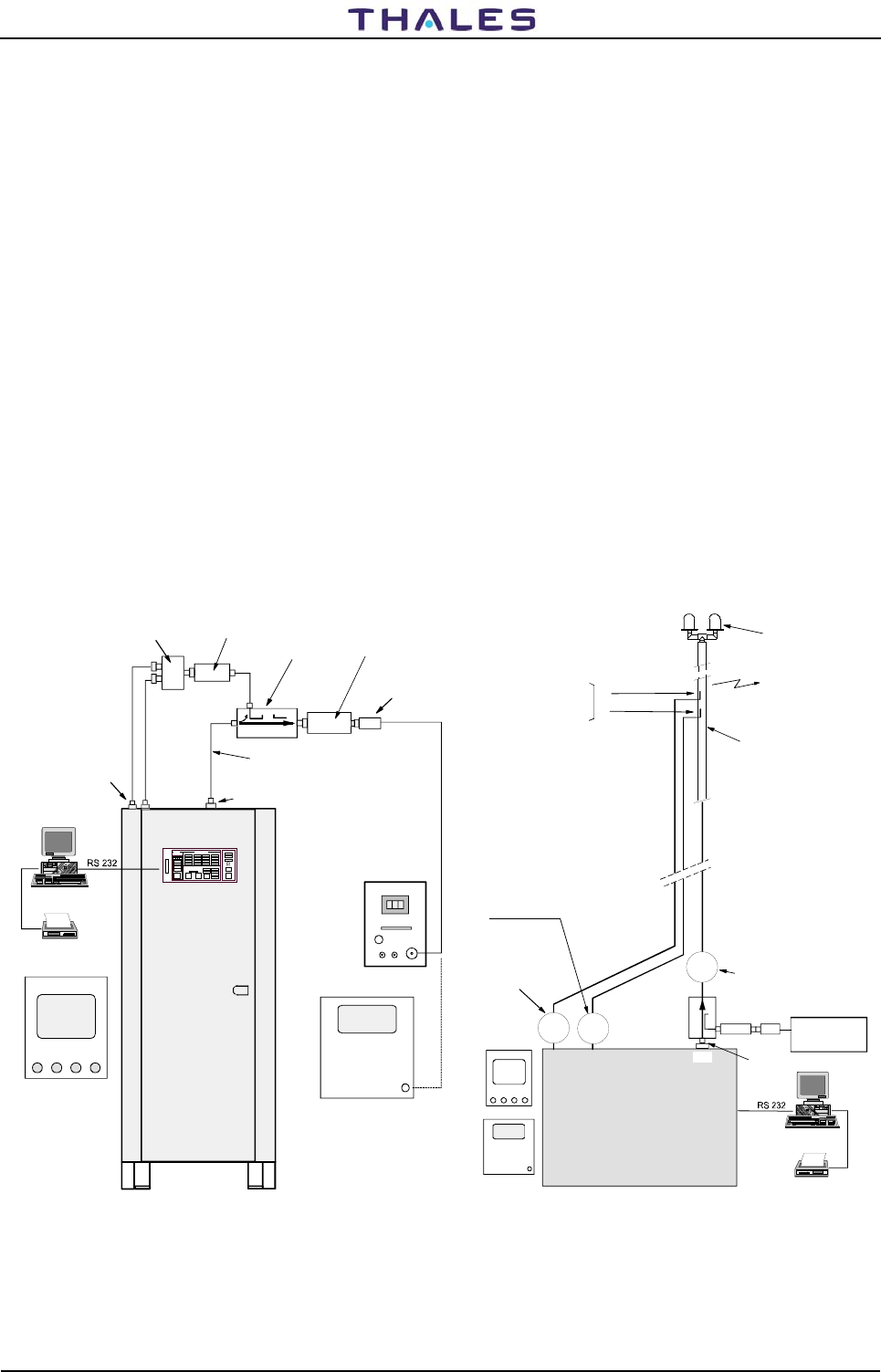
955 900 031 C DME 415/435 -Technical Manual
Vol. 1-Section 5 - Maintenance
5-20 THALES Italia S.p.A.- A. S. D. Vers. D, September 2005
5.3.4 Peak power output Calibration Procedure
NOTE This procedure must be carried out during the installation, in the event of substitution of module
TX100 or/and TKW and also in case the channel change.
The alignment is possible only on site (not by Remote Control)
For calibration in the presence of antenna RF cables see section 2 - Installation and for measurements of
Power Reading by the monitors, see procedures described in paragraphs 5.3.7.
TX and TKW modules are equipped with EEPROM serial memory in which are memorized the data used by
the software of automatic modulation. This software controls the leveling of the output power, specific
channel and mode operating, and the optimization of the pulse shape. A special software package
(EEPROM TX /TKW) is made for EEPROM reading and writing. This software is included in the "equipment
manager" program (see section ANNEX D in this volume).
The software (EEPROM TX /TKW) is allowed on following conditions:
1) MAINTENANCE mode (see the section ANNEX D "WINDME400 equipment manager" in this volume)
2) The two transponders should be in stand by status
3) Instruments necessary for calibration:
oscilloscope, peak power wattmeter, attenuators, spectrum analyzer
The instrumentation of test set-up for measurements is shown in figure 5.3.
DME 400
directional
Coupler
20 dB
Power meter
Sensor
30 cm RG214 coax cable-
Connect. "N" male
Power
splitter
Connecteur
des monitors
de sondes
d'Antenne
Attenuator:
50 dB/100W
Attenuator:
6 dB/20W
oscilloscope
Peak
power
Meter
Spetrum
Analyzer
Printer
PC
Antenna monitors
connectors Antenna
connector
obstruction lights
11
1213
Antenna
coax cable
Equipment DME
1
2
Peak Power
meter
Transmitted
Power
PAD
SK1 Peak
power
output
coupled antenna
probes
Printer
PC
oscilloscope
Spetrum
Analyzer
probe Mon.1
coax cable
probe Mon.2
coax cable
DME antenna
a) Lab. Test set-up b) Set-up with antenna cables, installed
Figure 5.3. Test set-up
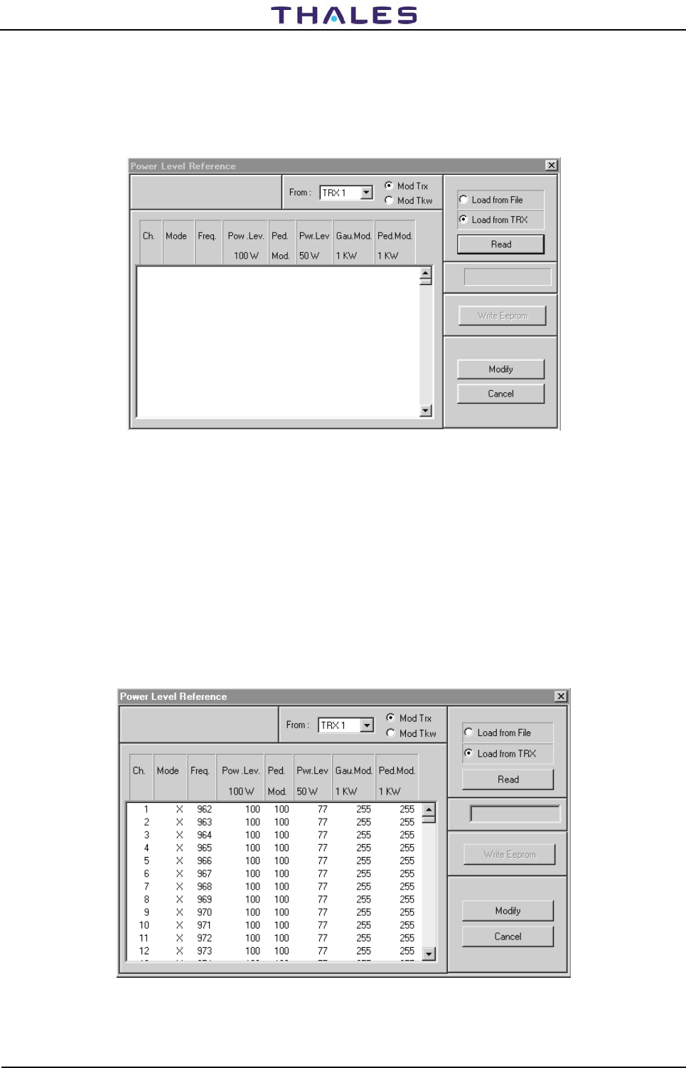
DME 415/435 -Technical Manual
Vol. 1-Section 5 - Maintenance 955 900 031 C
Vers. D, September 2005 THALES Italia S.p.A.- A. S. D. 5-21
5.3.4.1 DME 415 Program ACTIVATION
From "DME400 equipment manager" program in "Maintenance mode" and transponders in stand-by,
activate the software "E2prom TX/TKW", pressing, at the same time, the combination keys "CTRL+F10" on
the keyboard of the PC. The initial mask of references of figure 5.4 is shown for TRX 1 (or TRX 2 according
to the selection).
Figure 5.4. References initial mask for alignment of 100W peak power output
5.3.4.2 TX100 Modulation - adjust peak power output for DME 415
Starting from the mask of figure 5.4, to select the following options:
From: TRX 1 or TRX 2 and Mod Trx (100Wp transmitter)
"Load from File" for the parameters' reading when one chooses of to examine the existing default
values or memorized in a file of the directory c:\>winsv\site. Click on the key "Read" of figure 5.4
to carry out the action.
"Load from TRX" when it is necessary to visualize the parameters values written in the E2prom of TX100
module. Click on the key of figure 5.4 " Read " to carry out the action (after approximately 10
seconds the data values are displayed as in example of figure 5.5).
Figure 5.5. References Mask with values for Mod Trx (example)

955 900 031 C DME 415/435 -Technical Manual
Vol. 1-Section 5 - Maintenance
5-22 THALES Italia S.p.A.- A. S. D. Vers. D, September 2005
5.3.4.2.1 Meaning of the labels and data displayed (TX100)
Meaning of the labels and data displayed on figure 5.5:
NOTE: the values of the parameters reference of the fourth to eighth columns are expressed in counts,
that software of the DMD translated into voltage levels.
• The data of the first three columns (not modifiable) individualize the beacon parameter:
Ch - beacon channel
Mode of the beacon
Freq. operating transmitter frequency: the lines of the table of figure 5.5 are 252 and they result
ordinates for increasing frequencies. Through the slide cursor, the channel of interest is reached.
• The fourth column (Pow. Lev. 100W) is the level reference for 100W peak output power (DME415).
Value = 100 counts of default and values limits to be used: from 80 to 130 counts.
• The fifth column (Ped. Mod - Pedestal Modulation Duration) is the modulation duration of pedestal
referred to the 10% of the maximum peak detected pulse. Note that this parameter affects the
spectrum considerably. Value = 100 counts of default and values limits to be used: from 90 to 110
counts. The change of this parameter asks the check of the spectrum signals with spectrum analyzer.
• The sixth column (Pwr. Lev. 50W) is the level reference of power for 50W (DME415); refers to the
adjustment for the 3dB power reduction (see para. 5.3.6 Setting, "Transponder parameter"). Value =
70 counts of default and values limits to be used: from 50 to 90 counts.
• The seventh column (Gau. Mod. 1KW - Gaussian Modulation 1KW limit - not used for DME415) is the
limit of level of the Gaussian modulation for 1KW and is employed by the DME 435 to limit the
maximum variation of the AMC (Automatic Modulation Control). Value = 180/255 counts of default and
values limits to be used: from 32 on 255 counts. (see change values in para 5.3.4.2.2 also)
• The eighth column (Ped. Mod. 1KW - not used for DME415) Used for the voltage level calibration of
the pedestal. Is also the limit of maximum variation level of the pedestal modulation for DME435 1KW.
Value = 220/255 counts of default and values limits to be used: from 0 on 255 counts. (see change
values in para 5.3.4.2.2 also)
5.3.4.2.2 Modification of reference parameters values
Modify these parameters to select, with the pointer, the interested line of service channel and click on same
line. Therefore, click on the key of figure 5.5 "Modify". The mask "Modify References Maintenance" of
figure 5.6 will be displayed in which acting on the editable fields will be possible to perform the desired
reference changes.
Meaning of parameters displayed on figure 5.6:
• Power Level 100W: Reference in counts for the calibration of the 100W peak power
• Ped. Mod. Dur. duration time for modulation of the pedestal
• Power Level 50W: Reference in counts for the calibration to -3dB reduction peak power
• Gaussian Modulation 1KW: Not used - To always insert the value 255 counts when is used for DME
435
• Pedestal Modulation 1KW: Pedestal level. To always insert the value 255 counts when is used for
DME 435
• OK: press key to confirm the changes of the reference counts
• Cancel : press key turn back to the condition without modification
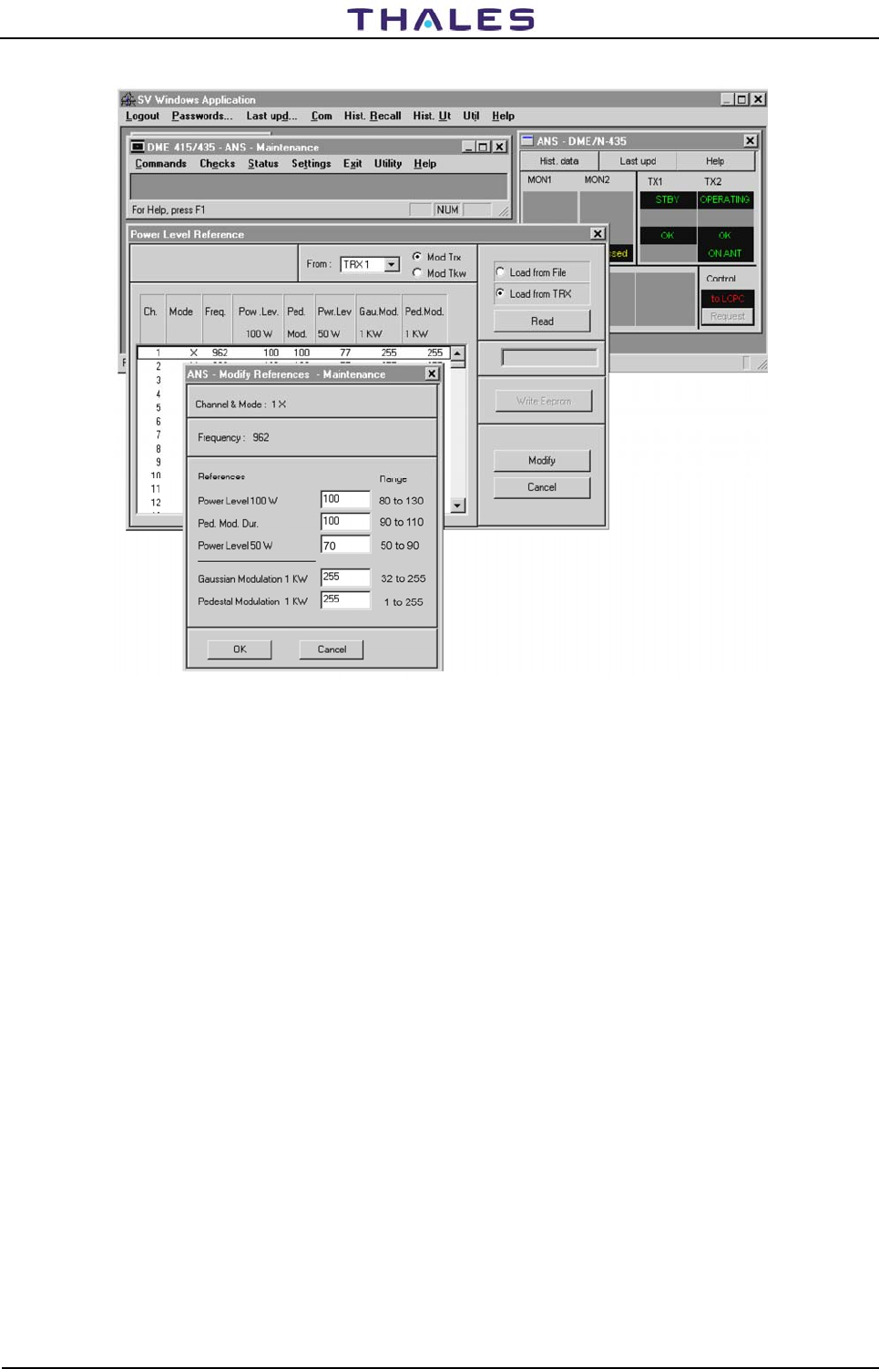
DME 415/435 -Technical Manual
Vol. 1-Section 5 - Maintenance 955 900 031 C
Vers. D, September 2005 THALES Italia S.p.A.- A. S. D. 5-23
Figure 5.6. Modify references values for Mod Trx (example)
Procedures for data change:
1) Modify the parameters (Power Level 100W), (Ped. Mod. Dur.) and (Power Level 50W):
Set in operate status the transponder TRX1 in antenna and to note the power result reading on the
"Peak Power Meter " of figure 5.3
2) Modify the values to obtain the reading of power 100Wp on Peak Power Meter. Click on button OK
after the modifications to confirm the changes
3) So ready, press key "Write EEPROM" (this will write the new parameters on E2prom of the module
and will create a file with the extension ".TMP" containing the new parameters). The box, under the
key "Write EEPROM", when illuminated, will show the advance of the process in progress.
4) Reset on module DMD to stored new arrangement (NOTE: maintain pressed the button of reset
during few seconds until to obtain lit red LED)
NOTE:. The Software of A.M.C. ("Automatic Modulation Control ") of DMD module acts as the
multiplying coefficient with the reference number for the 10% of the detected peak pulse signal
transmitted and changes the pedestal level on modulation signal. For example: one pulse
pedestal duration approximately of 5.8µs must be reduced from value current 100 (in COUNT) by
changing it into 95 (count). In this case, we will have: (95/100) * 5.8 = 0.95 * 5.8 = 5.51µs. The
5.51µs will be the new pedestal duration value; the width of pulse (measured at 50% of
amplitude) is also proportionally reduced.
REMARK: Whereas is replaced a module TX100 (and/or TKW), it is always necessary to perform the
reset hardware on DMD module with the purpose to align the DMD memory to the
EEPROMs data. The new data of the reference counts are stored in E2PROM, only after
having carried out the reset on DMD
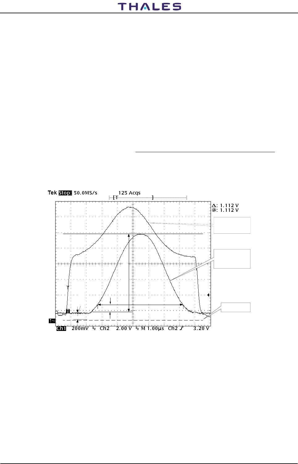
955 900 031 C DME 415/435 -Technical Manual
Vol. 1-Section 5 - Maintenance
5-24 THALES Italia S.p.A.- A. S. D. Vers. D, September 2005
5.3.4.3 Notation for the calibration of RF output power of the TX100
Prepare the instrumentation as of figure 5.3
NOTES:
a) The automatic modulation control (AMC) is obtained by the signal detected at output of the TX
module, which is addressed to the entry of the converter analog/digital of DMD module.
b) Channel 1 (CH1) of the oscilloscope is joined to detected signal RF on TX 100 output present on test-
point AN36 of DMD module
c) Channel 2 (CH2) of the oscilloscope is joined to the signal of modulation V_MOD present on test-point
AN13 of TX100 module
d) The trigger of external synchronism of the oscilloscope is joined on test-point AN11 of TX100 module
Figure 5.7 shows the waveform of the signal detected "V_det" (on test point AN36 DMD) with the main
parameters in the conditions of optimal full power. The waveforms have the following definitions:
1) V_det_peak: Value of the peak voltage detected, offset level excluded. Value dependent narrowly by
the modulation peak level (Typical value = 10mVolt x Counts in EEPROM: 1Vp for 100 counts).
2) 10% width: Duration of the detected pulse on 10% of peak level (typical 5,8 µs for 100 accounts,
5,1µs for 95 accounts).
3) Offset: typical level value, approximately 100 mVolt, added in factory adj. on DMD module
Ch1
Detected Signal
TP AN36 DMD
GND Level
Offset
Vdet_peak
10% width
CH2
Modulation Signal
V_MOD AN13 TX
10% Vpeak
Figure 5.7. Waveforms of detection for TX100
Figure 5.8 shows the waveform of the modulation signal "V_Mod" (on test point AN13 of TX100) with the
main parameters in the conditions of optimal full power. The waveforms have the following definitions:
1) Vmod_peak: Modulation peak voltage controlled by the DMD software. Values of 11Vp for the low
channels until 36Vp for the high channels
2) Vmod_ped: Modulation pedestal voltage level controlled by the DMD software to obtain one duration
to 10 % on the detected signal, (10% width). Values of 3V for the low channels until 8V for the high
channels.
3) Vmod_gauss: Peak voltage level of the modulation Gaussian part. Values of 5V for the low channels
until 30V for the high channels
4) Offset: Modulation level <1V factory adj. by the trimmer P1 of TX100 module
5) Droop_correction: Voltage difference between the peaks of the pairs pulses which, it is controlled by
the software of the DMD in order to minimize it.
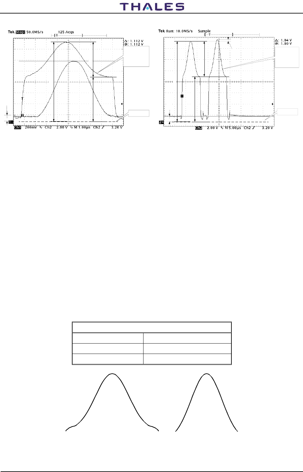
DME 415/435 -Technical Manual
Vol. 1-Section 5 - Maintenance 955 900 031 C
Vers. D, September 2005 THALES Italia S.p.A.- A. S. D. 5-25
GND Level
Offset
Vmod_peak
Ch2
Modulation
Signal
V_MOD
TP AN13 TX
Vmod_ped Vmod_gauss
Ch2
Modulation
Signal
V_MOD
TP AN13 TX
GND Level
Offset
Vmod_peak
Vmod_gauss
Vmod_ped
Droop correction
Figure 5.8. Waveforms of modulation for TX100
5.3.4.4 Calibration of output RF signal for TX100
1) With the equipment connected as figure 5.3 to measure the peak power output by wattmeter. The typical
precision of measurement will be: ±10% (consists of tolerance of: coupler, attenuators, ….)
2) Modify counts of the parameter "Power Level 100W" as figure 5.6 for 100 W reading on the Wattmeter of
figure 5.3.
3) Modify counts of the "Ped. Mod. Dur." parameters in order to obtain the pulse shape, similar to the
detected signal of figure 5.7. Avoid realizing pulses as in figure 5.9.
Comply with the tolerances of the pulse shape defined by ICAO as in table 5-4.
The counts " Ped. Mod. Dur." changes the values of pulse width with 10% of the peak level.
The counts "Pedestal Modulation" changes the levels of pedestal amplitude (typical value 255 counts).
Check with the spectrum analyzer which the spectrum is within the limits of the characteristics marked in
figure 5.36a) and, if necessary, to change the " Ped. Mod. Dur." count parameter for to obtain the
required results.
4) Set the transponders on standby status
5) Reset on module DMD to stored new arrangement
6) Press "Write E2prom" on figure 5.5
7) Reiterate this procedure for each counts reference values variation and for best results.
8) Repeat this procedure for Transponder 2
Table 5-4 Tolerance of pulse envelope gaussian
a) Pedestal level in excess
(seen on DMD TP AN36) b) Pedestal level deficient
(seen on DMD TP AN36)
Figure 5.9. Incorrect Gaussian Pulses shape
Envelope Gaussian - Tolerance ICAO
Pulse Rise time Not exceed 3 μs
Pulse Decay time Not exceed 3,5 μs
Pulse width (duration) 3,5 μs ±0,5 μs
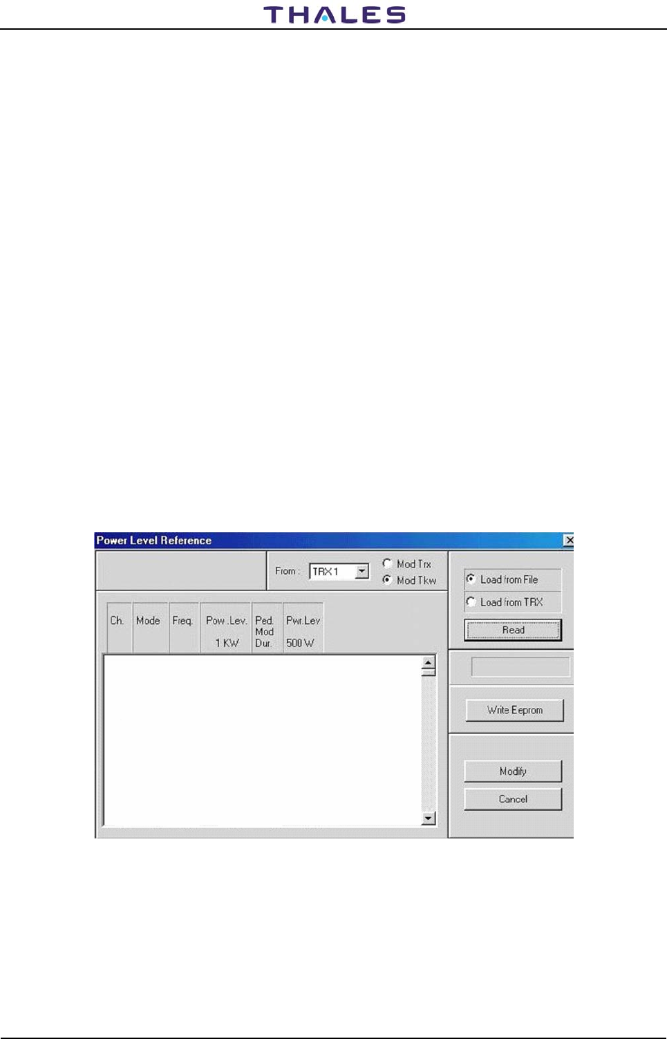
955 900 031 C DME 415/435 -Technical Manual
Vol. 1-Section 5 - Maintenance
5-26 THALES Italia S.p.A.- A. S. D. Vers. D, September 2005
5.3.5 TKW 1KW Peak power output Calibration Procedure
NOTE This procedure must be carried out during the installation, in the event of substitution of module
TKW and also in case the channel change.
The alignment is possible only on site (not by Remote Control)
For calibration in the presence of antenna RF cables see section 2 - Installation - and for measurements of
Power Reading by the monitors, see procedures described in paragraphs 5.3.7.
TX and TKW modules are equipped with EEPROM serial memory in which are memorized the data used by
the software of automatic modulation. This software controls the leveling of the output power, specific
channel and mode operating, and the optimization of the pulse shape. A special software package
(EEPROM TX /TKW) is made for EEPROM reading and writing. This software is included in the "equipment
manager" program (see section ANNEX D in this volume).
The software (EEPROM TX /TKW) is allowed on following conditions:
1) MAINTENANCE mode (see the section ANNEX D "WINDME400 equipment manager" in this volume)
2) The two transponders should be in stand by status
3) Instruments necessary for calibration:
oscilloscope, peak power wattmeter, attenuators, spectrum analyzer
The instrumentation of test set-up for measurements is shown in figure 5.3.
5.3.5.1 DME 435 1KW Program ACTIVATION
From "DME400 equipment manager" program in "Maintenance mode" and transponders in stand-by,
activate the software "E2prom TX/TKW", pressing, at the same time, the combination keys "CTRL+F10" on
keyboard of the PC. The initial mask of references of figure 5.10 is shown for TRX 1 (or TRX 2 according to
the selection).
Figure 5.10. References initial mask for alignment of 1KW peak power output
5.3.5.2 TKW 1KW Modulation - adjust peak power output for DME 435
Starting from the mask of figure 5.10, to select the following options:
From: TRX 1 or TRX 2 and Mod Tkw (1KWp transmitter)
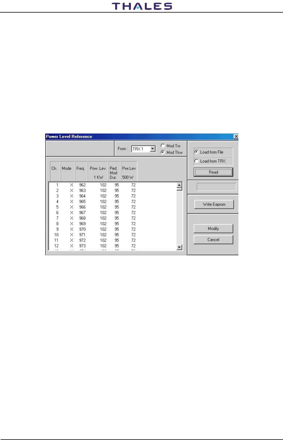
DME 415/435 -Technical Manual
Vol. 1-Section 5 - Maintenance 955 900 031 C
Vers. D, September 2005 THALES Italia S.p.A.- A. S. D. 5-27
"Load from File" for the parameters' reading when one chooses of to examine the existing default
values or memorized in a file of the directory c:\>winsv\site. Click on the key "Read" of figure 5.10
to carry out the action.
"Load from TRX" when it is necessary to visualize the parameters values written in the E2prom of TKW
module. Click on the key of figure 5.10 " Read " to carry out the action (after approximately 10
seconds the data values are displayed as in example of figure 5.11).
Check that on the operative channel, the Gau.Mod. 1KW and Ped.Mod. 1KW are "255 counts" for both. In
the opposed case, choose the channel and click on the button Modify to change the value according to
"255 "counts (see figure 5.6 f para 5.3.4.2.2) and click on the button OK. Click on the Write Eeprom key of
figure 5.6, to save the data in Eeprom of the module. Reset on DMD module to charge new arrangement
and to await initialization.
NOTE: Whereas the adjustment also of module TKW is concluded, the signal present in AN7 of TX100
will be similar on figure 5.13 and not more like figure 5.7.
Figure 5.11. References mask with values for Mod Tkw (example)
5.3.5.2.1 Meaning of the labels and data displayed (TKW)
Meaning of the labels and data displayed on figure 5.11:
NOTE: the values of the parameters reference of the fourth to sixth columns are expressed in counts,
that software of the DMD translated into voltage levels.
• The data of the first three columns (not modifiable) individualize the beacon parameter:
Ch - beacon channel
Mode of the beacon
Freq. operating transmitter frequency: the lines of the table of figure 5.11 are 252 and they result
ordinates for increasing frequencies. Through the slide cursor, the channel of interest is reached.
• The fourth column (Pow. Lev. 1KW) is the level reference for 1KW peak output power (DME435).
Value = 100 counts of default and values limits to be used: from 80 to 130 counts.
• The fifth column (Ped. Mod - Pedestal Modulation Duration) is the modulation duration of pedestal
referred to the 10% of the maximum peak detected pulse. Note that this parameter affects the
spectrum considerably. Value = 100 counts of default and values limits to be used: from 90 to 110
counts. The change of this parameter asks the check of the spectrum signals with spectrum analyzer.
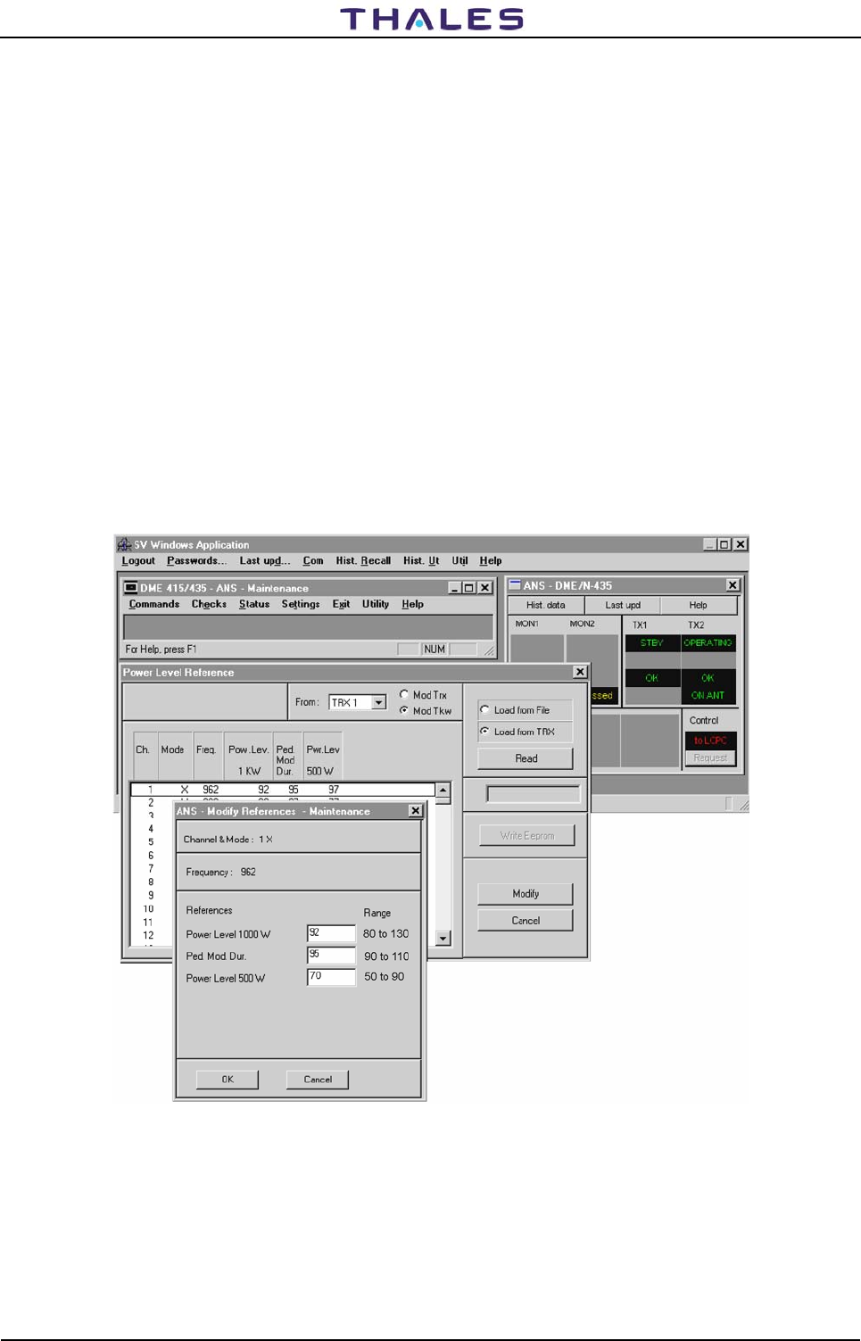
955 900 031 C DME 415/435 -Technical Manual
Vol. 1-Section 5 - Maintenance
5-28 THALES Italia S.p.A.- A. S. D. Vers. D, September 2005
• The sixth column (Pwr. Lev. 500W) is the level reference of reduced power at 500W (DME4135);
refers to the adjustment for the 3dB power reduction (see para. 5.3.6 Setting, "Transponder
parameter"). Value = 70 counts of default and values limits to be used: from 50 to 90 counts.
5.3.5.2.2 Modification of reference parameters values
Modify these parameters to select, with the pointer, the interested line of service channel and click on same
line. Therefore, click on the key of figure 5.11 "Modify". The mask "Modify References Maintenance" of
figure 5.12 will be displayed in which acting on the editable fields will be possible to perform the desired
reference changes.
Meaning of parameters displayed on figure 5.11
• Power Level 1000W: Reference in counts for the calibration of the 1000W peak power
• Ped. Mod. Dur. duration time for modulation of the pedestal
• Power Level 500W: Reference in counts for the calibration to -3dB reduction peak power
• OK: press key to confirm the changes of the reference counts
• Cancel : press key turn back to the condition without modification
Figure 5.12. Modify references values for Mod Tkw (example)
Procedures for data change:
1) Modify the parameters (Power Level 100W), (Ped. Mod. Dur.) and (Power Level 500W):
Set in operate status the transponder TRX1 in antenna and to note the power result reading on the
"Peak Power Meter " of figure 5.3

DME 415/435 -Technical Manual
Vol. 1-Section 5 - Maintenance 955 900 031 C
Vers. D, September 2005 THALES Italia S.p.A.- A. S. D. 5-29
2) Modify the values to obtain the reading of power 1000Wp on Peak Power Meter. Click on button OK
after the modifications to confirm the changes.
3) So ready, press key "Write EEPROM" (this will write the new parameters on E2prom of the module
and will create a file with the extension ".TMP" containing the new parameters). The box, under the
key "Write EEPROM", when illuminated, will show the advance of the process in progress.
4) Reset on module DMD to stored new arrangement (NOTE: maintain pressed the button of reset
during few seconds until to obtain lit red LED)
NOTE:. The Software of A.M.C. ("Automatic Modulation Control " of DMD module) acts as the
multiplying coefficient with the reference number for the 10% of the detected peak pulse signal
transmitted and changes the pedestal level on modulation signal. For example: one pulse
pedestal duration approximately of 5.8µs must be reduced from value current 100 (in COUNT) by
changing it into 95 (count). In this case, we will have: (95/100) * 5.8 = 0.95 * 5.8 = 5.51µs. The
5.51µs will be the new pedestal duration value; the width of pulse (measured at 50% of
amplitude) is also proportionally reduced.
REMARK: Whereas is replaced a module TX100 (and/or TKW), it is always necessary to perform the
reset hardware on DMD module with the purpose to align the DMD memory to the
EEPROMs data. The new data of the reference counts are stored in E2PROM, only after
having carried out the reset on DMD
5.3.5.3 Notation for the calibration of RF output power of the TKW
Prepare the instrumentation as of figure 5.3
NOTES:
a) The automatic modulation control (AMC) is obtained by the signal detected at output of the TKW
module, which is addressed to the entry of the converter analog/digital of DMD module.
b) Channel 1 (CH1) of the oscilloscope is joined to detected signal RF on TKW output present on test-
point AN36 of DMD module
c) Channel 2 (CH2) of the oscilloscope is joined to the signal of modulation V_MOD present on test-point
AN13 of TX100 module
d) The trigger of external synchronism of the oscilloscope is joined on test-point AN11 of TX100 module
Figure 5.7 shows the waveform of the signal detected "V_det" (on test point AN36 DMD) with the main
parameters in the conditions of optimal full power. The waveforms have the following definitions:
1) V_det_peak: Value of the peak voltage detected, offset level excluded. Value dependent narrowly by
the modulation peak level. (Typical value = 10mVolt x Counts in EEPROM:1Vp for 100 counts)
2) 10% width: Duration of the detected pulse on 10% of peak level (typical 5,8 µs for 100 accounts,
5,1µs for 95 accounts).
3) Offset: typical level value, approximately 100 mVolt, added in factory adj. on DMD module
5.3.5.4 Calibration of output power RF for TKW
1) With the equipment connected as figure 5.3 to measure the peak power output by wattmeter. The typical
precision of measurement will be: ±10% (consists of tolerance of: ±1 count, coupler, attenuators, ….)
2) Modify counts of the parameter "Power Level 1000W" as figure 5.12 for 1000 W reading on the
Wattmeter of figure 5.3.
3) Modify counts of the "Ped. Mod. Dur." parameters in order to obtain the pulse shape, similar to the
detected signal of figure 5.7 (TP AN36 DMD). Avoid realizing pulses as in figure 5.9.
Comply with the tolerances of the pulse shape defined by ICAO as in table 5-4.
The counts " Ped. Mod. Dur." changes the values of pulse width with 10% of the peak level.
Check with the spectrum analyzer which the spectrum is within the limits of the characteristics marked in
figure 5.36b) and, if necessary, to change the " Ped. Mod. Dur." count parameter for to obtain the
required results.
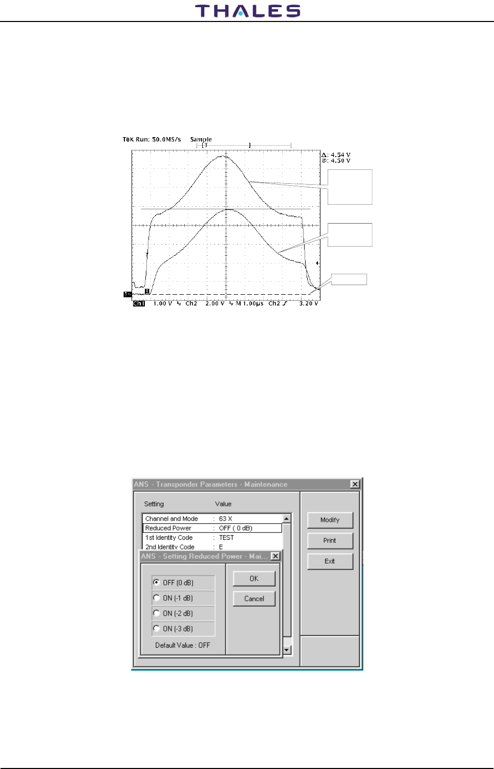
955 900 031 C DME 415/435 -Technical Manual
Vol. 1-Section 5 - Maintenance
5-30 THALES Italia S.p.A.- A. S. D. Vers. D, September 2005
4) Set the transponders on standby status
5) Reset on module DMD to stored new arrangement
6) Press "Write E2prom" on figure 5.11
7) Reiterate this procedure for each counts reference values variation and for best results
8) Repeat this procedure for Transponder 2
Ch2
Modulation
Signal
V_MOD
TP AN13 TX
Ch1
Detected Signal
TP AN7 TX
GND Level
Figure 5.13. Pulse shape for TX100 drive of TKW (example)
5.3.6 Reduced power - Check operation
Setting power reduction as figure 5.14
Perform the check on every 4 points of figure 5.14, given on the following values of output power:
0dB OFF reduction - Corresponds to the 100% of full power
-1dB ON reduction - Corresponds to the approx. 79% of full power
-2dB ON reduction - Corresponds to the approx. 63% of full power
-3dB ON reduction - Corresponds to the approx. 50% of full power. This last level comes established
while preparing the counts indicated in figure 5.6 (for DME415) or 5.12 (for DME435).
Figure 5.14. Setting Reduced power
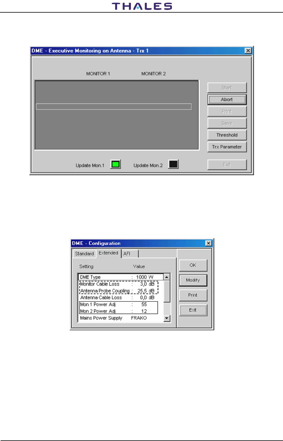
DME 415/435 -Technical Manual
Vol. 1-Section 5 - Maintenance 955 900 031 C
Vers. D, September 2005 THALES Italia S.p.A.- A. S. D. 5-31
5.3.7 Adjustment Power Monitor Reading
Reply Delay
Reply Delay
Reply efficiency
Pulse spacing
Peak Power Output
Transmission Rate
Transmitter Freq.
Transmitted Power
50,01
98
12.00
1062
805
1020.0
1001
Watt
ppps
MHz
Watt
%
µs
µs
50,00
96
12.00
805
Watt
ppps
MHz
Watt
%
µs
µs
1065
1000
1020.0
Figure 5.15. Screen of correct measurement by Monitor 1 & 2 (Example)
To adjust value of Peak Power Output (see figure 5.15) you have to change the following value of preset:
- MON1 Power Adj
- MON2 Power Adj
The range value is from –100 to +100. See figure 5.16.
Figure 5.16. Screen of configuration for power reading adjustment
To adjust value of Transmitted Power for both monitors, you have to change the values of preset. See
figure 5.16
- Monitor Cable Loss
- Antenna Probe Coupling
There is also a possibility to adjust value of power for each monitor, so you can align monitor1 with monitor2
by TRIMMER P6 on monitor board.
NOTE: Be careful !!!! Don’t touch any other TRIMMER on monitor board
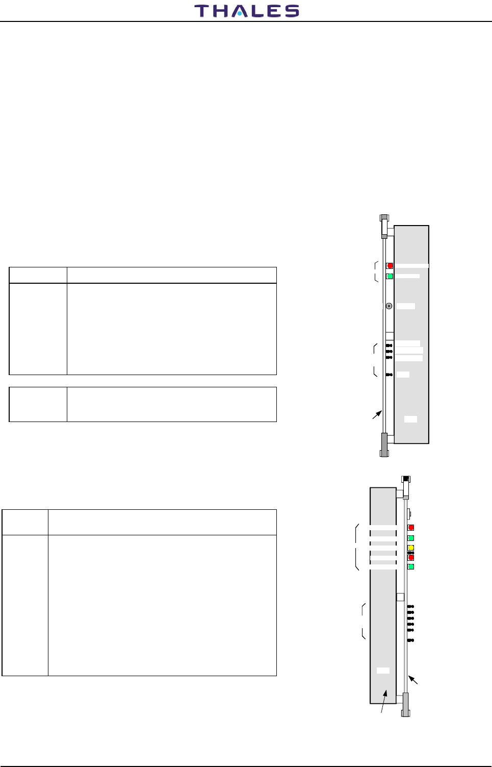
955 900 031 C DME 415/435 -Technical Manual
Vol. 1-Section 5 - Maintenance
5-32 THALES Italia S.p.A.- A. S. D. Vers. D, September 2005
5.3.8 Test Points and Led
The external test points (and LED position), to be found on the front of the beacon modules (see figures
5.17; 5.18 ; 5.23; 5.25, 5.26; 5.28; 5.30; 5.33; 5.34; 5.35) and the lists are on tables: 5-5 to 5-13.
The LED on beacon modules are listed in section 3, on table 3-7 and shown in figures 3.31 to 3.33
5.3.9 Waveform
Significant wave shapes relating to the test points are on the following pages.
The DME 415 & DME 435 equipments spectrums (typical) of the transmitted signal are shown in figures
5.36A) and 268H5.36B) respectively.
For every wave shape and for each scope channel the following information is given: scale used (in V/div),
time base (in μs/div or in ms/div) and test point providing the synchronization signal, if an external
synchronization signal is used for the measurement. If there is no synchronization indication, the
synchronization is internal.
Table 5-5. Power Supply PWS module - External test points
TEST POINT DESCRIPTION
TP1 Used to check for +5 V stabilized voltage. Typical
value: 5,1 ± 0,1V
TP2 Used to check for +15 V stabilized voltage. . Typical
value: +15± 0,2V
TP3 Used to check for −15 V stabilized voltage. . Typical
value: -15± 0,2V
TP4 GND
SW1 Reset Pushbutton - Check operation for verifier
transient failure of module,
when red led is lighted.
Figure 5.17. PWS outline – Test point and LED
Table 5-6. Monitors MON module - External test points
TEST
POINT DESCRIPTION
AN11 H MORCO – Identity Code - Detected identified Morse
code signal.
AN34 OUT MUX - ADC input signals - RF pulses detected from
antenna probes
AN23 A MOD –Analog signals of the interrogation Modulation
AN 71 MEAS. SYNC. - Signal trigger on oscilloscope for BITE
measurement .
AN2 LM INT - Start generation and acquisition signal. Trigger on
oscilloscope for check Executive Monitoring
measurements.
AN45 GND
Figure 5.18. MON outline – Test point and LED
Power
Supply
INPUT (green)
PWS FAULTY (red)
RESET
GND
TP2 +15V
TP1 +5V
TP3 -15V
P
W
S
PBA PWS
Test
points
LED
SW1
Monitor
WATCH DOG (red)
IDENTITY (green)
TRX ALARM (yellow)
MON FTY (red)
EXEC. MON (green)
AN2 LM INT
AN11 (H MORCO)
AN23 A MOD
AN71 MEAS SYNC
AN34 OUT MUX
AN45 GND
M
O
N
PBA
MON
LED
Test
points
RF circuits
Casting
RESET
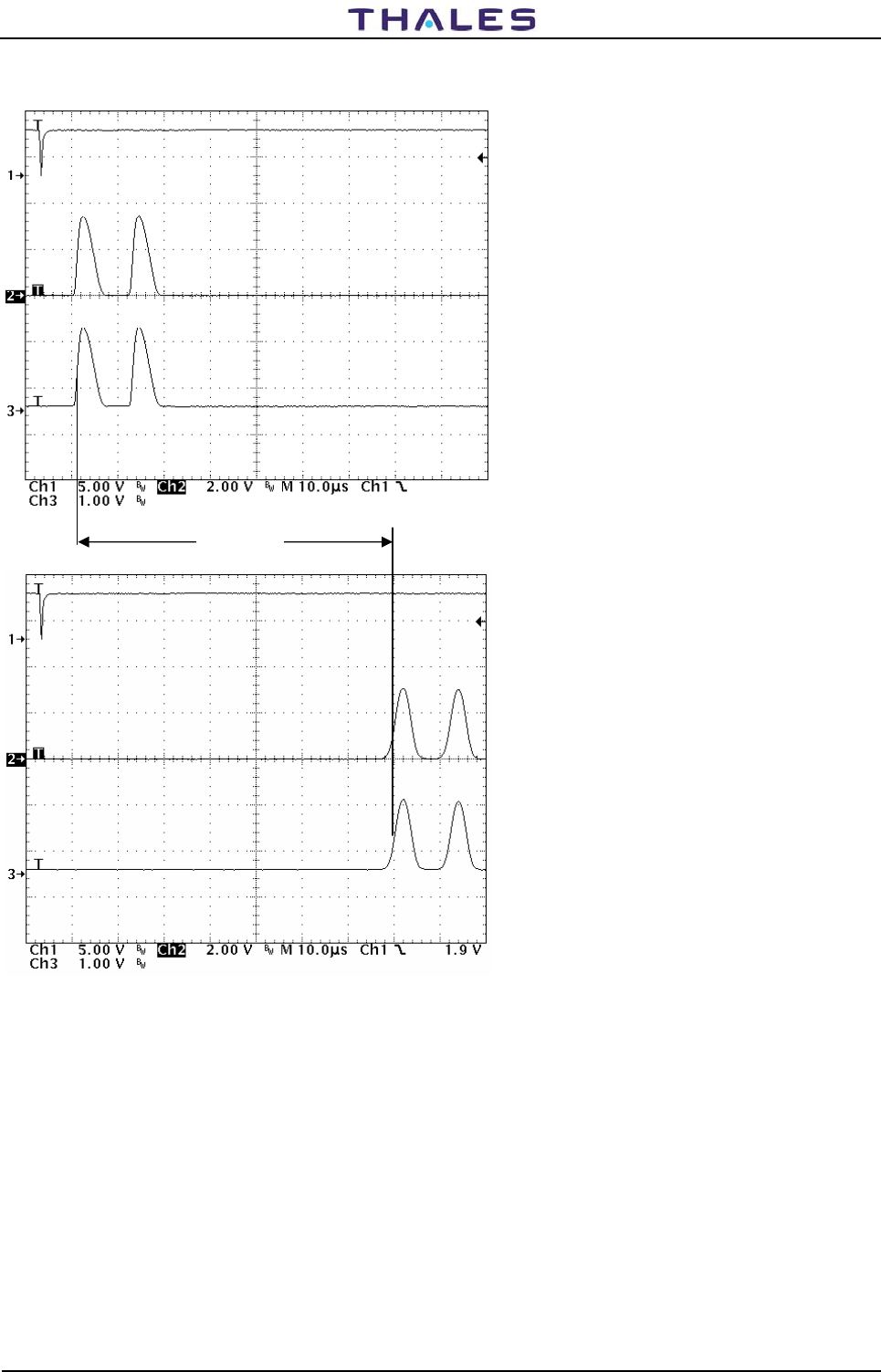
DME 415/435 -Technical Manual
Vol. 1-Section 5 - Maintenance 955 900 031 C
Vers. D, September 2005 THALES Italia S.p.A.- A. S. D. 5-33
Figure 5.19. MON module – Waveform monitor: X mode Interrogation
CH1-ext trigger –Test Point.=AN71
CH2-63 MHz DET – Test Point internal
CH3-ADC Input – Test Point = AN34
interrogation signal
CH1-ext trigger –Test Point.=AN71
CH3-ADC Input – Test Point = AN34
Reply detected by monitor
Reply Delay
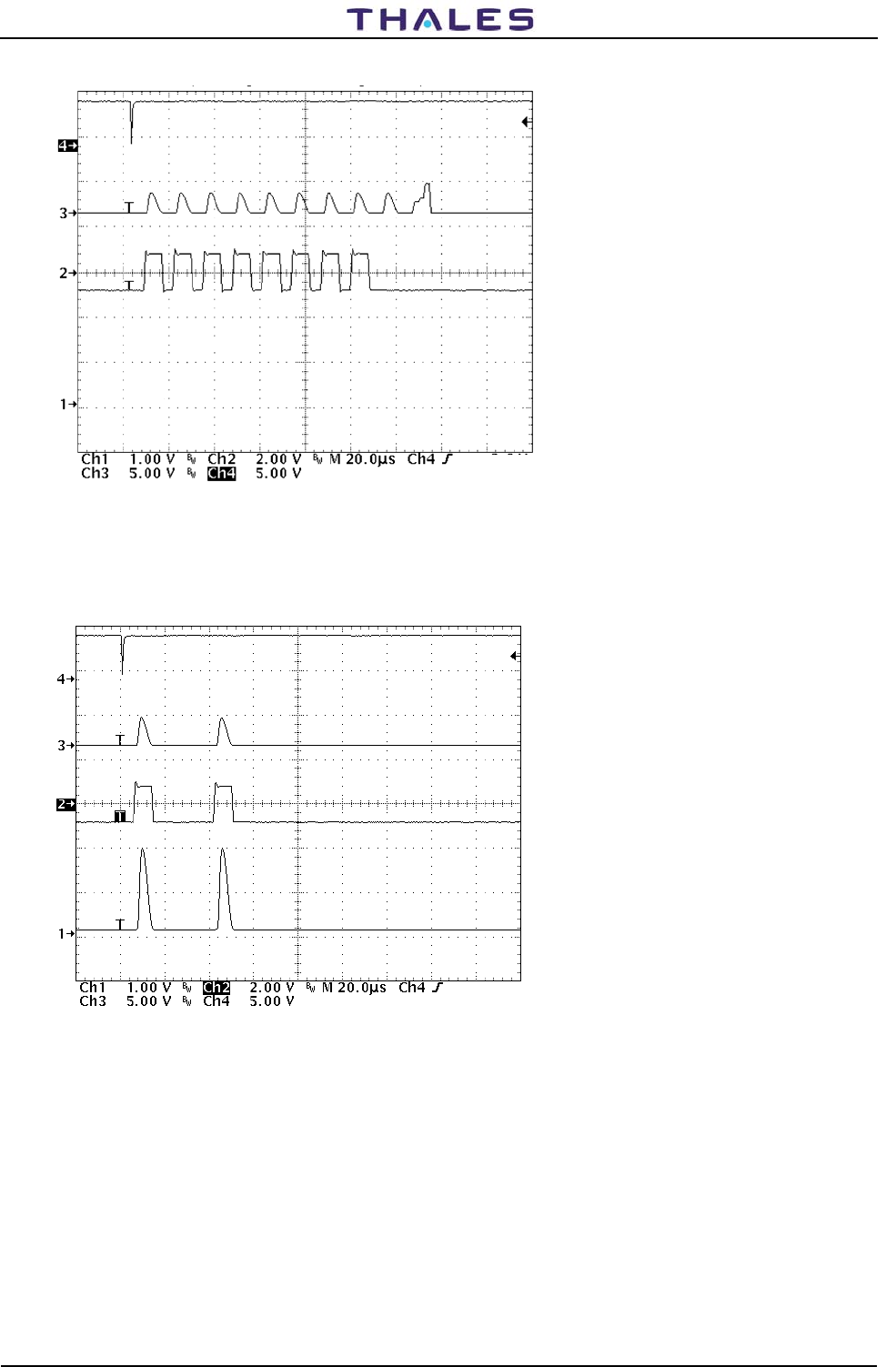
955 900 031 C DME 415/435 -Technical Manual
Vol. 1-Section 5 - Maintenance
5-34 THALES Italia S.p.A.- A. S. D. Vers. D, September 2005
Figure 5.20. MON module – Waveform monitor self-check: Attenuators check
Figure 5.21. MON module – Waveform monitor self-check: Y mode Interrogation
CH4-ext trigger –Test Point.=AN71
CH3-VTF signal – Test Point = internal
CH2- ON/OFF 63MHz enable – Test Point AN43
CH4-ext trigger –Test Point.=AN71
CH3-VTF signal – Test Point = internal
CH2- ON/OFF 63MHz enabl.– Test Point AN 43
CH1-ADC Input – Test Point = AN34
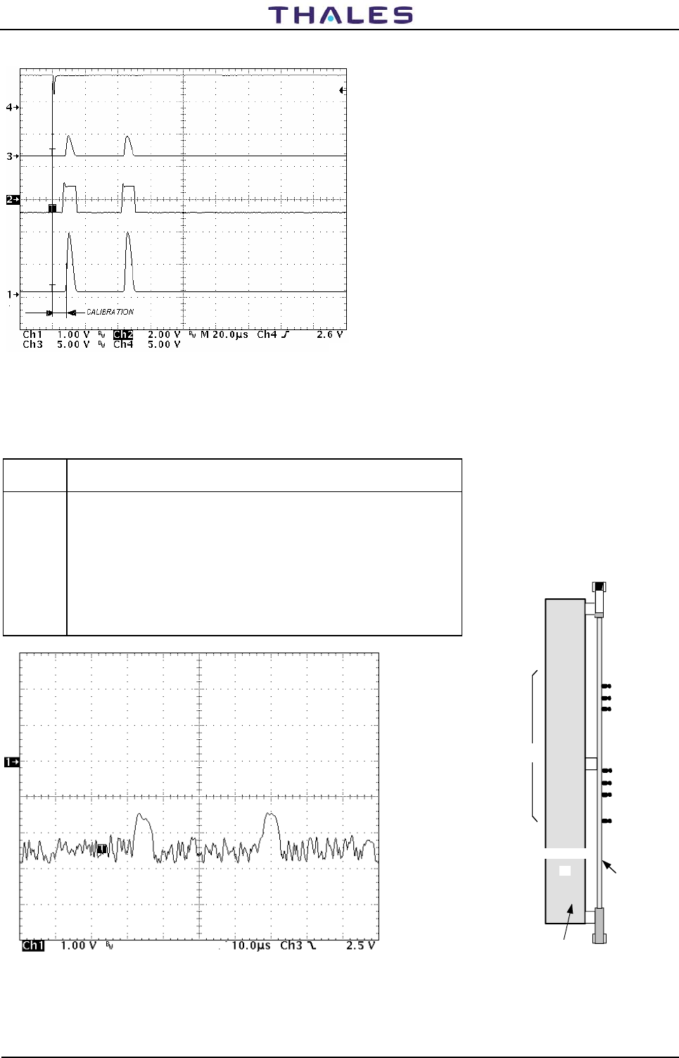
DME 415/435 -Technical Manual
Vol. 1-Section 5 - Maintenance 955 900 031 C
Vers. D, September 2005 THALES Italia S.p.A.- A. S. D. 5-35
Figure 5.22. MON module – Waveform monitor self-check: CALIBRATION Delay
Table 5-7. Receivers RX module - External test points
TEST
POINT DESCRIPTION
AN51 TOA Time of Arrival signal (N.U.).
AN OCV analog - On Channel Validation analog signals pair pulses
AN OCV Trigg. - On Channel Validation trigger gate digital signals
AN19 LOG N - Detected log signal output.
AN20 LOG-P - N.U.
AN7 CAL - Gate during pilot pulse Calibration. Signal trigger for log detected
measurement on oscilloscope
AN18 GND
Figure 5.23. RX outline – Test point and LED
Figure 5.24a. RX module – LOG N waveform Y mode
CH4-ext trigger –Test Point.=AN71
CH3-VTF signal – Test Point = internal
CH2- ON/OFF 63MHz enabl.– Test Point AN 43
CH1-ADC Input – Test Point = AN34
CH1-Log N
Test Point.=AN19
-90dBm interrog. level
AN 52 OCV-TR
Receiver
AN57 OCV
AN19 LOG N
AN20 LOG P
AN18 GND
PBA
RX
AN51 TOA
R
X
RF and IF circuits
casting
Test
points
AN 7 L-CAL
NOTE: these waveforms are visualized during the
interrogation towards the Rx. Previously acquisition by
calibration is carried out internal to the Monitor with single
pulse
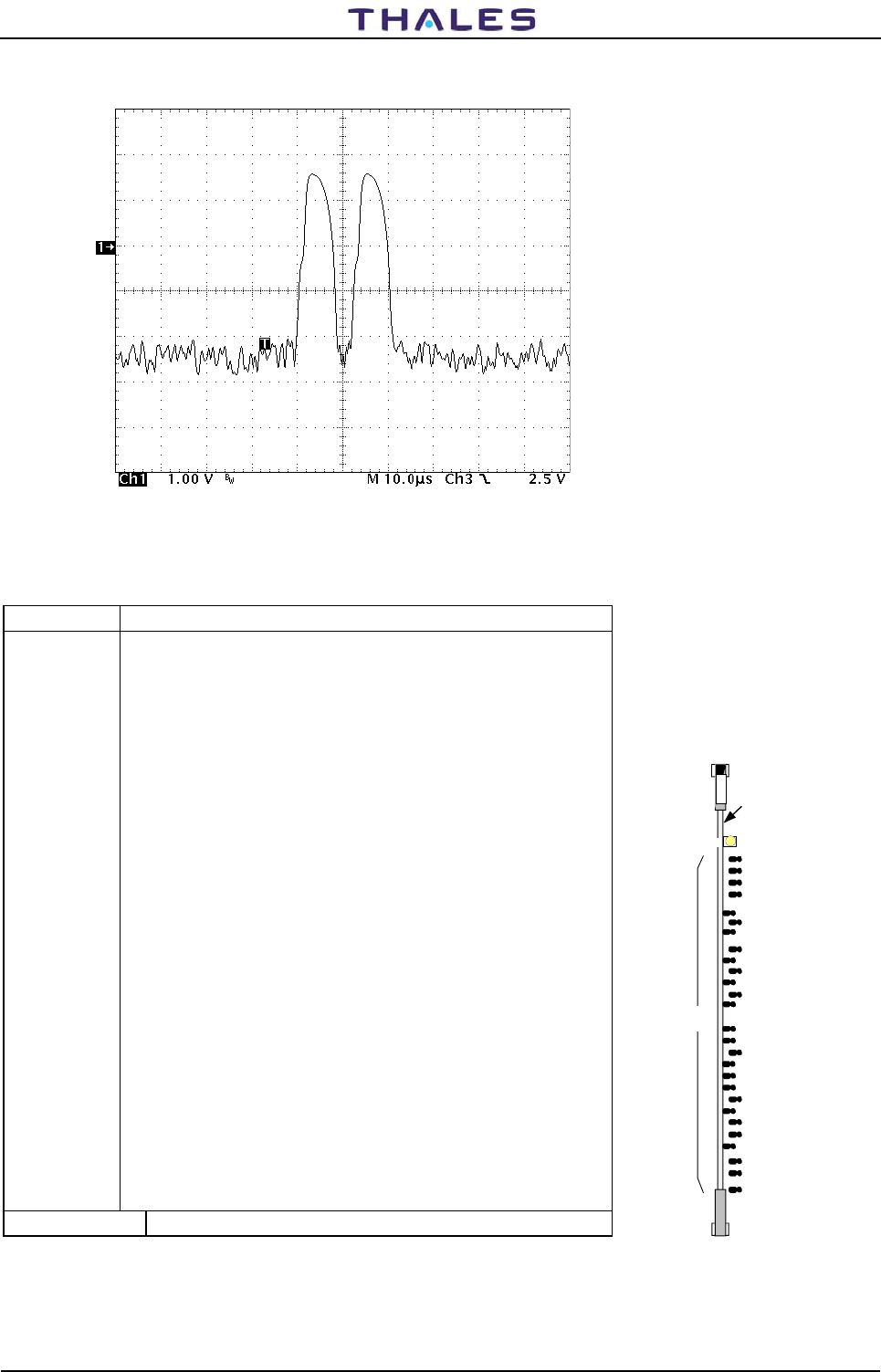
955 900 031 C DME 415/435 -Technical Manual
Vol. 1-Section 5 - Maintenance
5-36 THALES Italia S.p.A.- A. S. D. Vers. D, September 2005
Figure 5.24b. RX module – LOG N waveform X mode
Table 5-8. Digital Processor DPR module - External test points
TEST POINT DESCRIPTION
AN20 SQI - Squitter pulses
AN19 DPNPSQ - Squitter/reply pulses
AN18 DAEDT - Dead time signal gate
AN17 MORCO - Used to check Morse code identity
AN32 LOG - Remake log Rx signal from internal DAC
AN13 OVRL - Transmission rate overload frequency (4800 Hz)
AN56 GND
AN16 SPINH - Spacing Inhibit (minimum squitter spacing)
AN15 IDT - Identity frequency (1350 Hz)
AN52 TRGOUT - Output trigger delay-compare comparator
AN40 TOA N - TOA Output digital trigger
AN39 MOD ST - Modulation start
AN5 MD - Main delay gate
AN7 HRXINH - Gate Rx inhibit during transmitted pulse
AN1 CAL - Calibration gate for scope trigger used to check pilot pulse signal
AN41 SQIDBP - Squitter-Identity (gate enable calibration pilot pulse)
AN9 GF – Gate former decoded
AN43 GND
AN11 AGRDW - N.U. (Automatic gain reduction down)
AN10 AGREN - N.U. (Automatic gain reduction enable)
AN59 NPR - Dc level of presetting Rx sensitivity.
AN51 TH COMP - Threshold TOA signal comparator
AN50 DISCH - Discharge gate TOA signal
AN57 DISAB - Disable TOA signal
AN55,AN54,AN14 N.U.
Figure 5.25. DPR outline – Test point and LED
Digital
Processor
IDENT.(yellow)
AN40 TOA N
AN39 MOD ST
AN5 MD
AN1 CAL
AN41 SQIDBP
AN43 GND
AN19 DPNPSQ
AN18 DEADT
AN17 MORCO
AN20 SQI
PBA
LED
Test
points
DPR
D
P
R
AN32 LOG
AN56 GND
AN16 SPINH
AN55 N.U.
AN15 IDT
AN13 OVRL
AN54 N.U.
AN14 N.U.
AN52 TRGOUT
AN7 HRXINH
AN9 GF
AN11 AGRDW
AN10 AGREN
AN59 NPR
AN51 TH_COMP
AN50 DISCH
AN57 DISAB
CH1-Log N
Test Point.=AN19
-30dBm interrog. level
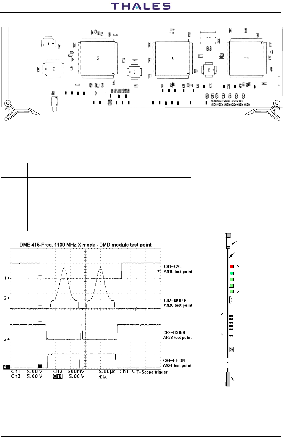
DME 415/435 -Technical Manual
Vol. 1-Section 5 - Maintenance 955 900 031 C
Vers. D, September 2005 THALES Italia S.p.A.- A. S. D. 5-37
AN20
AN19
AN18
AN17
AN32
AN56
AN55
AN54
AN16
AN52
AN15
AN14
AN40
AN39
AN7
AN1
AN41
AN43
AN5
AN8
AN48
AN9
AN11
AN10
AN59
AN51
AN50
AN57
RD4
Figure 5.26 DPR module – Test point position
Table 5-9. Digital Modulator DMD module - External test points
TEST
POINT DESCRIPTION
AN5 Trigger - N.U. (used to check specific maintenance measurement)
AN24 RF ON - Gate RF transmitter enable
AN23 LRX INH - Gate Rx inhibit
AN26 MOD N - Modulation pulse (gaussian and pedestal waveform)
N10 CALIB - Gate calibration of pilot pulse
AN39 GND
Figure 5.27. DMD module – Waveform, X mode
Figure 5.28. DMD
outline – Test point and LED
AN39 GND
WDOG
(red)
MOD
(green)
CAL
(green)
COD
(green)
CHK
(green)
AN10 CALIB
AN26 MOD N
AN23 RXINH
AN24 RF ON
AN5 TRIG
D
M
D
PBA
LED
Test
points
DMD
Modulator
CM1
Pushbutton
TRx on ANT.
RESET
UPPER
EXTRACTOR
LOWER
EXTRACTOR
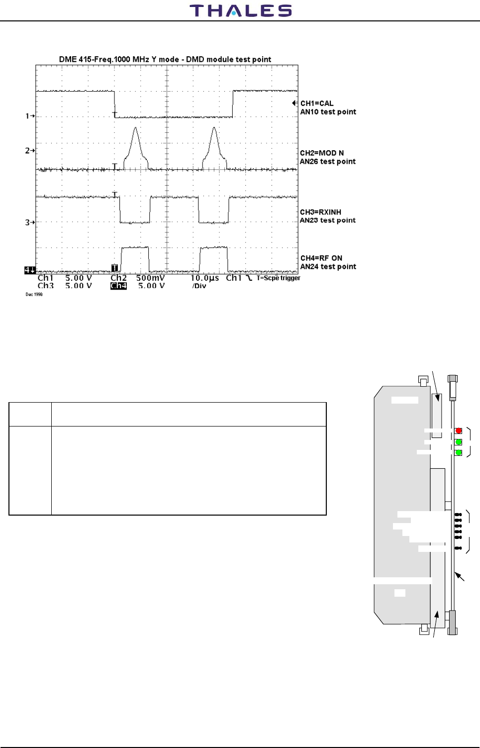
955 900 031 C DME 415/435 -Technical Manual
Vol. 1-Section 5 - Maintenance
5-38 THALES Italia S.p.A.- A. S. D. Vers. D, September 2005
Figure 5.29. DMD module – Waveform, Y mode
Table 5-10. Transmitter /driver TX module - External test points
TEST
POINT DESCRIPTION
AN17 DC/DC converter regulated voltage - 100 W module (typical values:
50V/transmitter/driver)
AN13 V MOD - Video Modulation Voltage (gaussian and pedestal waveform).
AN12 N.U. (Mod P)
AN11 MOD SQR - Modulation square gate
AN7 RF DET - Output RF detected signal .
AN21 GND
Figure 5.30. TX outline – Test point and LED
TX
AN21 GND
RF PROT (red)
RF ON (green)
DC/DC ON (green)
AN17 DC/DC OUT
AN13 V MOD
AN12 MOD P - N.U.
AN11 MOD SQR
AN7 RF DET
T
X
DC/DC converter
Heat Sink
RF circuits
casting
PBA
Test
points
LED
Transmitter/driver
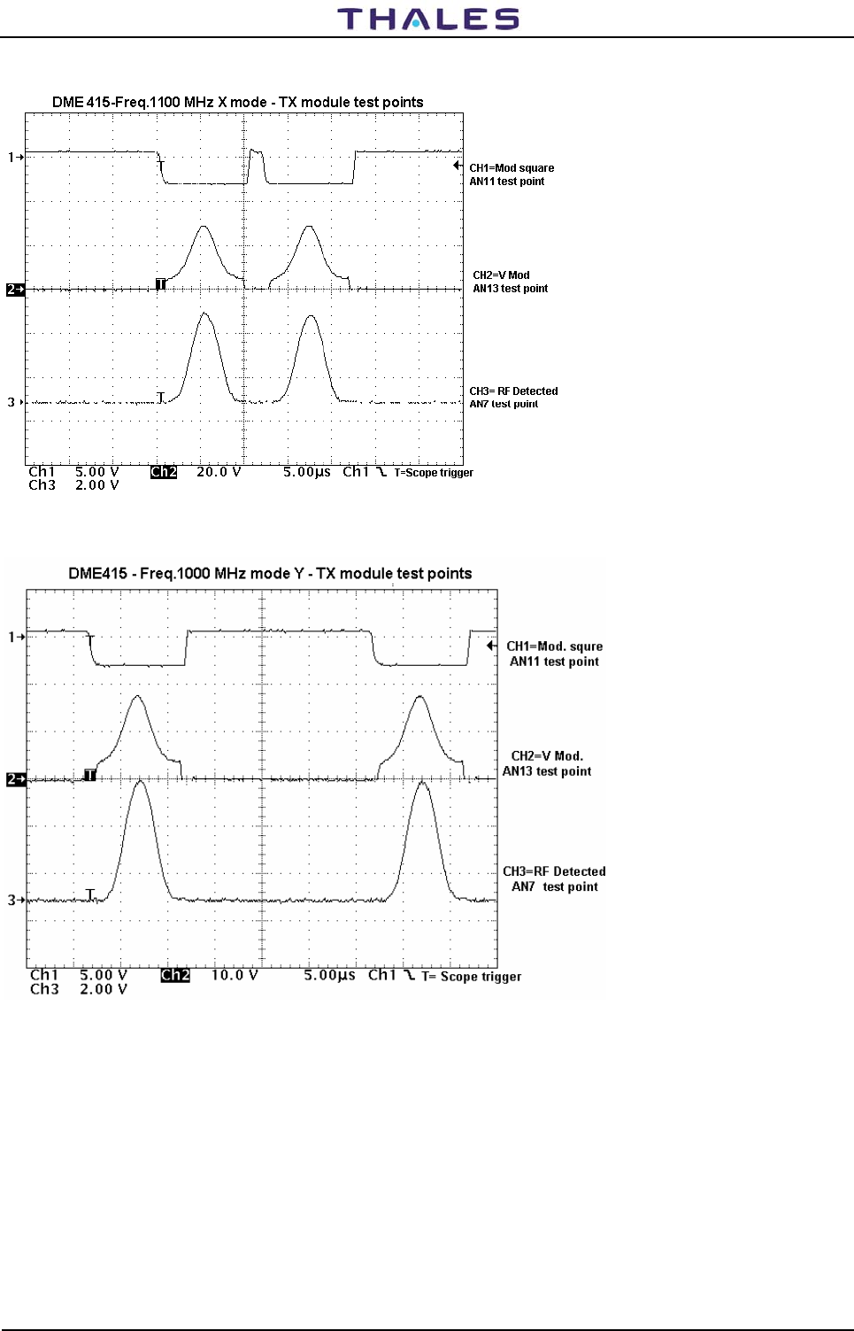
DME 415/435 -Technical Manual
Vol. 1-Section 5 - Maintenance 955 900 031 C
Vers. D, September 2005 THALES Italia S.p.A.- A. S. D. 5-39
Figure 5.31. TX module – Waveform – X mode
Figure 5.32. TX module – Waveform – Y mode
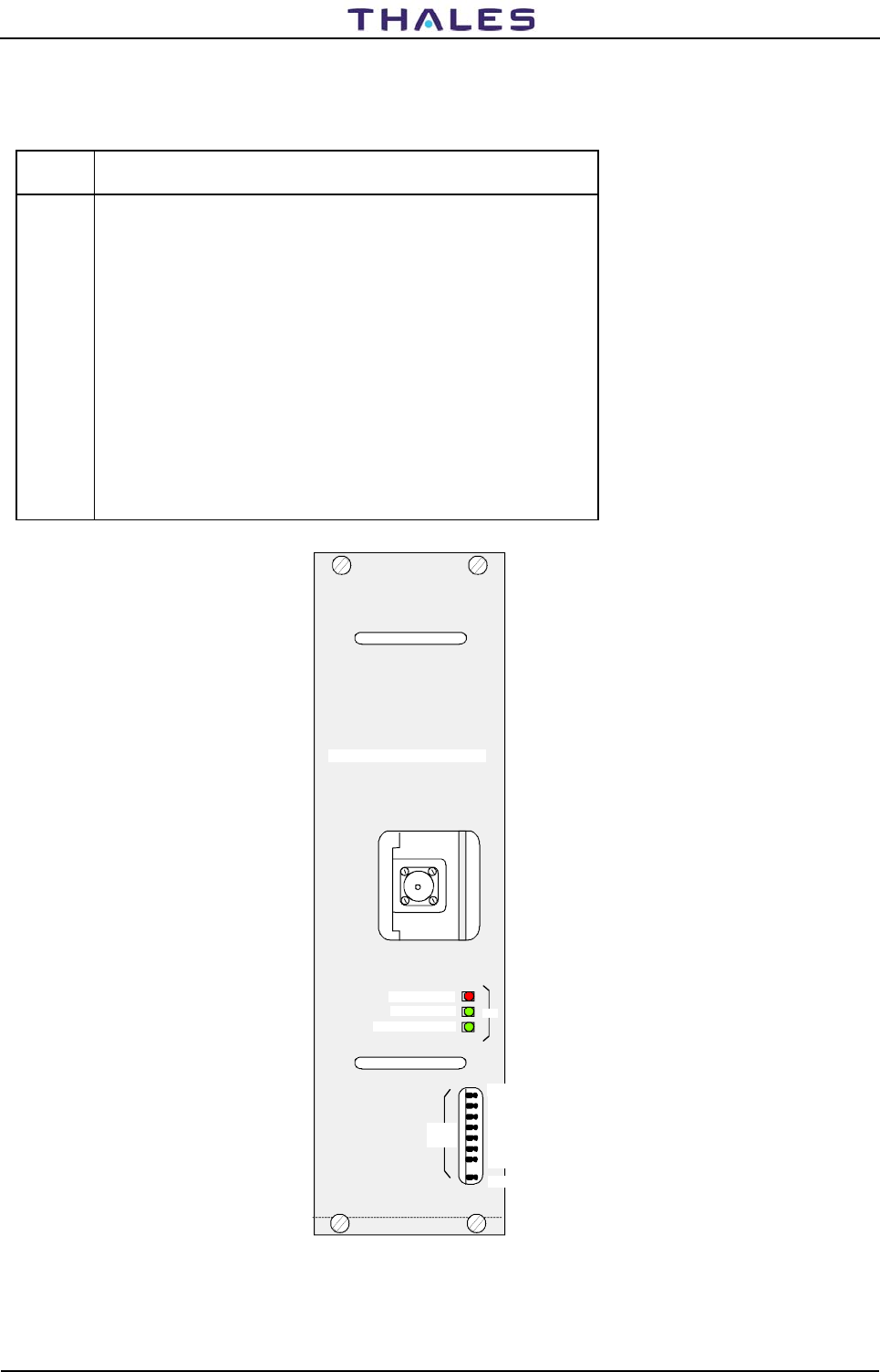
955 900 031 C DME 415/435 -Technical Manual
Vol. 1-Section 5 - Maintenance
5-40 THALES Italia S.p.A.- A. S. D. Vers. D, September 2005
Table 5-11. RF 1KW Amplifier TKW module (only DME 435) - External test points
TEST
POINT DESCRIPTION
AN1 200W DC/DC regulated voltage; output value: 50V ±0,5V
AN2 Used to verify the absorption current of the final driver RF power amplifier;
typical value measured between AN2 and the reference point AN1. Typical
value: ≤350 mV (conversion factor 1 mV/1 mA).
AN3 Similar to AN2 but used to verify the current of the first final power
amplifier.
AN4 Similar to AN2 but used to verify the current of the second final power
amplifier.
AN5 Similar to AN2 but used to verify the current of the third final power
amplifier.
AN6 Similar to AN2 but used to verify the current of the fourth final power
amplifier.
AN7 Used to verify the detected RF signal output by the TKW module.
AN8 GND
TKW
RF PROT (red)
RF ON (green)
DC/DC ON (green)
AN DC/DC OUT
AN V1
AN V2
AN V3
AN V4
AN V5
AN RF DET
AN GND
Test
points
LED
1 KW Transmitter Amplifier
Figure 5.33. TKW module outline – Test point and LED
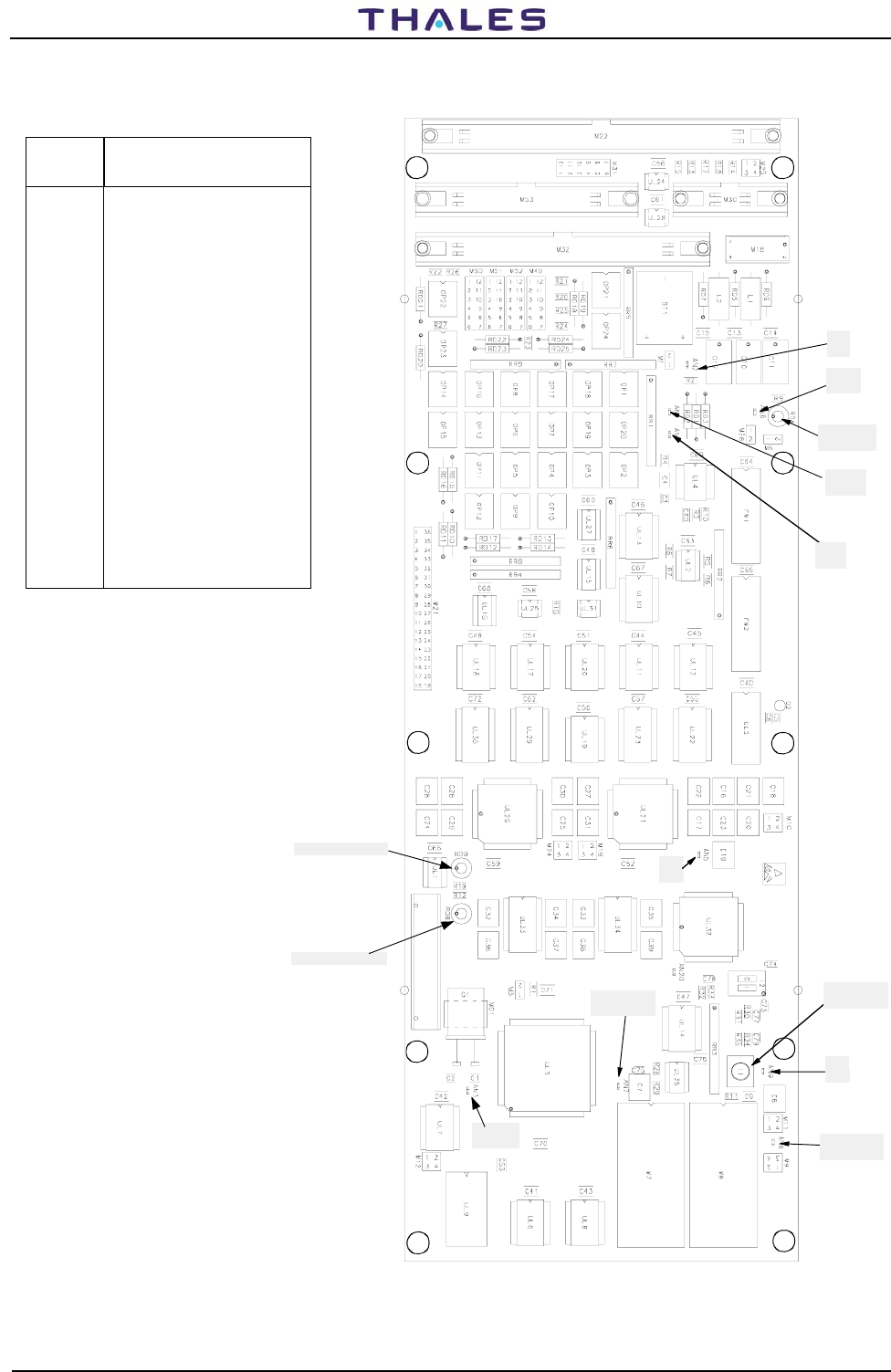
DME 415/435 -Technical Manual
Vol. 1-Section 5 - Maintenance 955 900 031 C
Vers. D, September 2005 THALES Italia S.p.A.- A. S. D. 5-41
Table 5-12. CSB Module Test Points
AN5
BRG
AN3
Freq. Q1
TX line green led
RX line green led
AN2
BT1
AN6
CPU WRITE
AN9
GND
AN7
CPU READ
AN8
BATF
CPU RESET
Pushbutton
AN4
VBAC
Watchdog
green led
AN1
INTSCC
Figure 5.34. CSB Module – Test point position
TEST
POINT DESCRIPTION
AN1 INTSCC0-Interrupt serial
Communic. Controller -TTL
level
AN2 BT1- Backup battery -3.6 V
nom; 5 V full charge; 2.8 V
depleted
AN3 Freq. Xtal Q1 - 14745.6 kHz
- pseudo-sine wave
AN4 VBAC - RTC supply voltage
3.6 V with standard load
AN5 BRG - Baud Rate Generator
- Frequency = 7,372,800 Hz
AN6 WR - CPU Write -
AN7 RD - CPU Read -
AN8 BATF - BT1 Battery
defective or depleted -
Normal = Flag High
AN9 GND
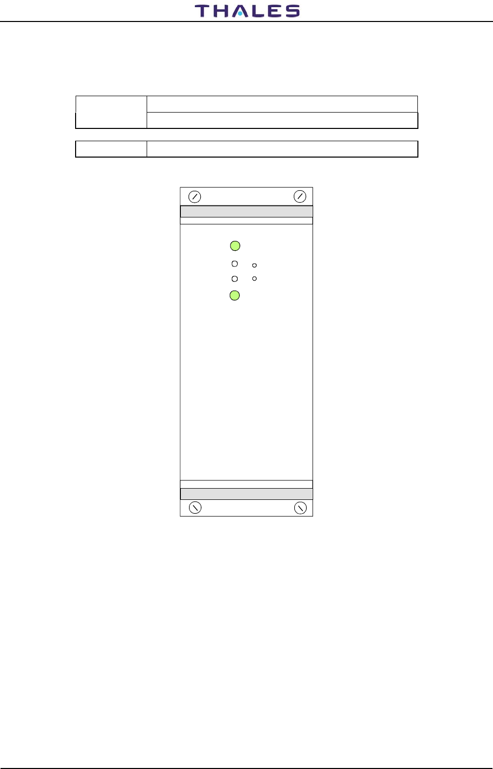
955 900 031 C DME 415/435 -Technical Manual
Vol. 1-Section 5 - Maintenance
5-42 THALES Italia S.p.A.- A. S. D. Vers. D, September 2005
Table 5-13. AC/DC Module Test Points
TEST POINT DESCRIPTION
TP+/ TP- Used to verify 54 Vout voltage.
V Adj Output voltage adjustment : ± 1 V max variation (53 to 55 Vdc)
AC/DC
Module OK
Mains OK
V adj
-TP
+
-
Figure 5.35. ACDC module – Test points and LED outline
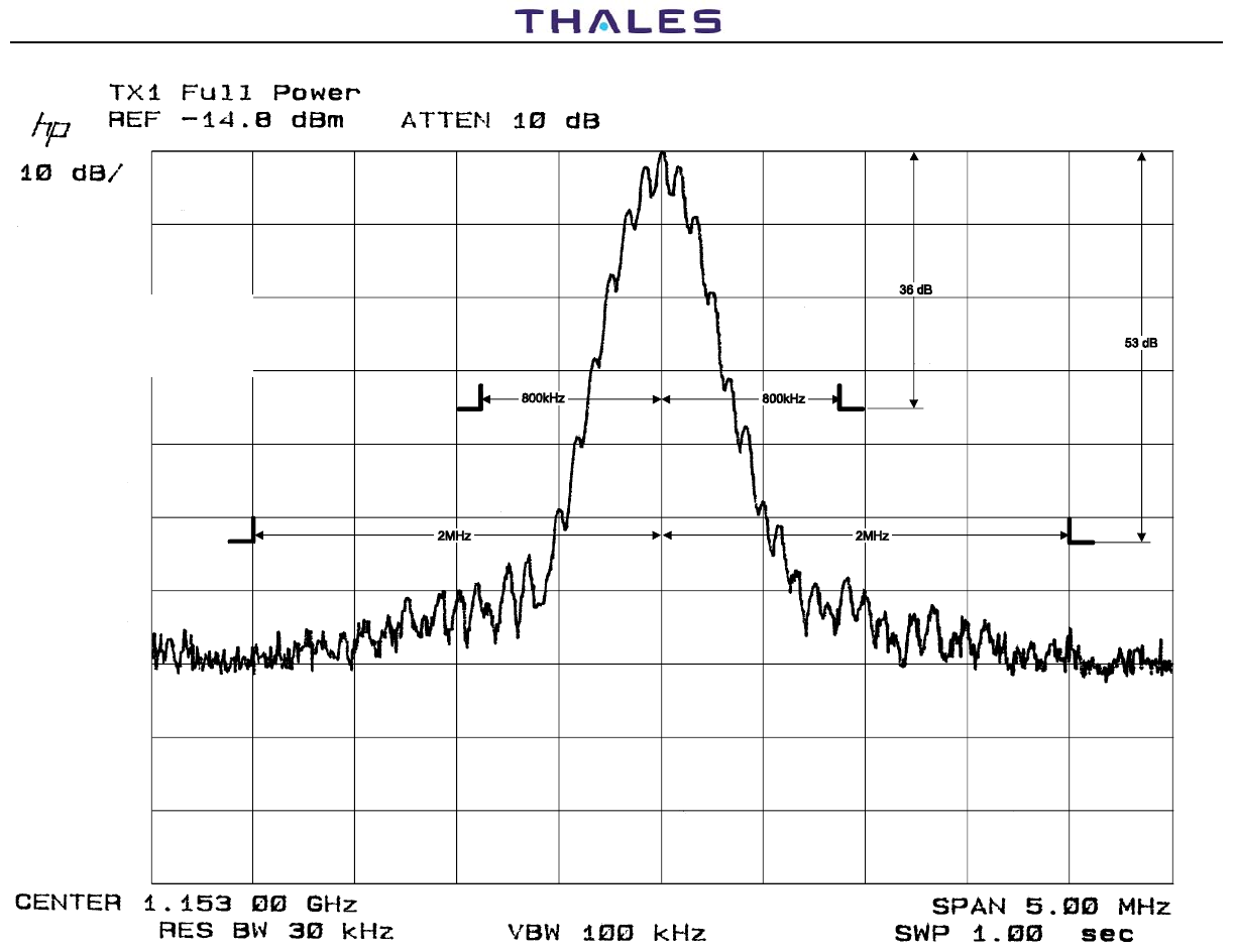
DME 415/435 -Technical Manual
Vol. 1-Section 5 - Maintenance 955 900 031 C
Vers. D, September 2005 THALES Italia S.p.A.- A. S. D. 5-43
5-43
ERP
(Effective Radiated Power)
Typical value: 50 dBmp
considering:
antenna gain = 9dB and
cable loss = 0dB
Figure 5.36a). DME 415 -Typical transmitted spectrum signal
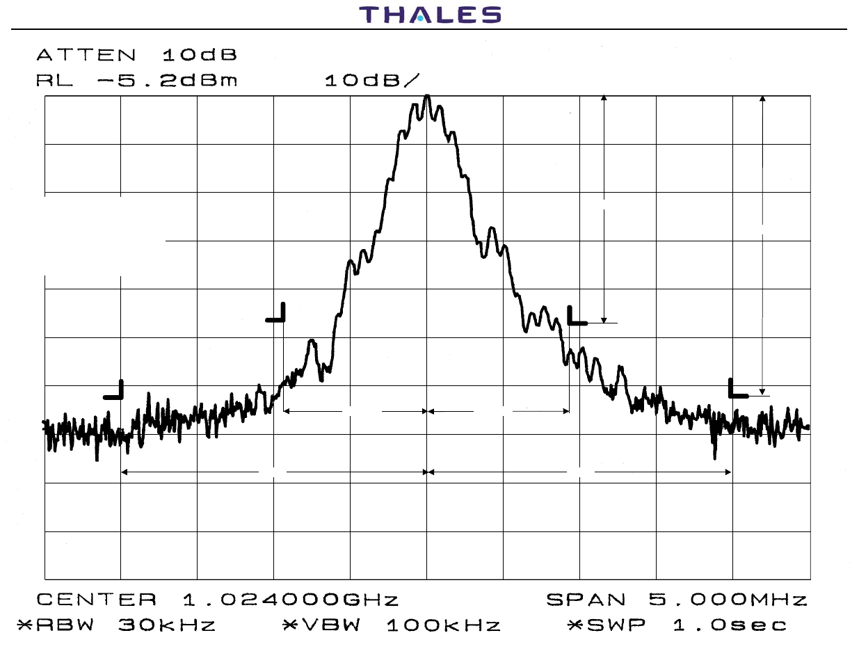
DME 415/435 -Technical Manual
Vol. 1-Section 5 - Maintenance 955 900 031 C
Vers. D, September 2005
THALES Italia S.p.A.- A. S. D. 5-44
5-44
800kHz 800kHz
2MHz 2MHz
46 dB
63 dB
ERP
(Effective Radiated Power)
Typical value: 60 dBmp
considering:
antenna gain = 9dB and
cable loss = 0dB
Figure 5.36b). DME 435 -Typical transmitted spectrum signal