Thomson Broadcast and Multimedia LBD-25200 Affinity L-Band Transmitter for Mobile Media Svs. User Manual Affinity LBD 200C N1 DRAFT1

Thomson Broadcast & Multimedia, Inc. Affinity L-Band Transmitter for Mobile Media Svs. Affinity LBD 200C N1 DRAFT1

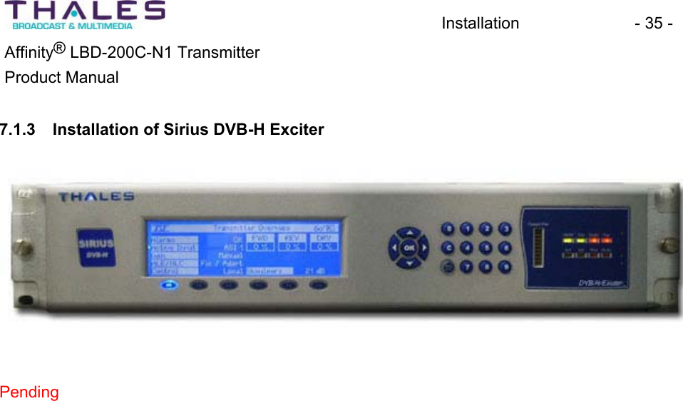
200W User Manual part 1

AAffffiinniittyy®®220000--WWaattttLLBBDD--220000CC--NN11LL--BBaannddDDiiggiittaallTTrraannssmmiitttteerrPPRREELLIIMMIINNAARRYYDDRRAAFFTTPPrroodduuccttMMaannuuaall
Safety NoticeIn compliance with Federal Regulations, 29 CFR 1910.1200, Material Data Sheets (MSDS) areprovided for each potentially hazardous material supplied. Please review this informationthoroughly.Document Number: DRAFTRevision: P1Date: September 29, 2005 Copyright © 2005 by Thales Broadcast & Multimedia Inc., All rights reserved.Affinity® is a Registered Trademark of Thales Broadcast & Multimedia, Inc. No part of this manual may be reproduced, stored in a retrieval system, or transmitted in any form or by any means, electronic, mechanical, photocopying, recording, or otherwise, except as may be expresslypermitted in writing by Thales Broadcast & Multimedia, Inc.Information provided by Thales Broadcast &Multimedia, Inc. is intended and believed to be accurate; however, no liability can be assumed for its use. Materials, designs, and specifications are subject to change without noticeFor technical support call 1-800-345-9295 or log on to our web site at www.thales-bm.com.Manufactured in the United States of America
Table of Contents  - i - ®Affinity  LBD-200C-N1 TransmitterProduct Manual 1 Preface.............................................................................................................................. 12 Introduction ....................................................................................................................... 23 Safety Information .............................................................................................................33.1 Introduction .......................................................................................................... 33.2 Warnings, Cautions, and Notes............................................................................ 33.3 Safety Symbols .................................................................................................... 43.4 Electrical Shock and the Human Body.................................................................43.5 Emergency Procedures for Electrical Shock ........................................................ 53.6 Transmitter Electrical Hazards ............................................................................. 64 Features ............................................................................................................................ 74.1 Overview .............................................................................................................. 74.2 Affinity® Low Power Transmitter Configurations.................................................. 84.3 Affinity® Family Construction ............................................................................... 84.4 Additional Affinity® Features:............................................................................. 115 Specifications .................................................................................................................. 125.1 Affinity® LBD-200C-N1 Transmitter Specifications............................................ 125.2 Affinity® LBD-200C-N1 Cabinet Layout ............................................................. 245.3 Affinity® LBD-200C-N1 FRU Part Numbers....................................................... 265.4 Fusing and Protection ........................................................................................ 275.5 Equipment Packaging ........................................................................................ 285.5.1 Unpacking and Inspection ........................................................................... 285.6 Environment Considerations .............................................................................. 285.7 System Grounding ............................................................................................. 296 General System Description ........................................................................................... 307 Installation ....................................................................................................................... 327.1 Installation of Transmitter Sub-Chassis.............................................................. 327.1.1 Installation of Site Management System ..................................................... 337.1.2 Installation of Satellite Receiver and Remultiplexer .................................... 347.1.3 Installation of Sirius DVB-H Exciter ............................................................. 357.1.4 Installation of Driver Plug-In Modules.......................................................... 36
Table of Contents  - ii - ®Affinity  LBD-200C-N1 TransmitterProduct Manual 7.1.5 Installation of Power Amplifier Segments .................................................... 377.1.6 Installation of Front-End Power Supplies ....................................................387.1.7 Installation of UPS System .......................................................................... 407.1.8 Installation of Downconverter ...................................................................... 418 Site Management System Description ............................................................................ 438.1 Status Monitoring and Control System............................................................... 439 Satellite Receiver and Remultiplexer Description ........................................................... 4410 Sirius DVB-H Exciter Description .................................................................................... 4510.1 Introduction ........................................................................................................ 4510.1.1 Remote Operation...................................................................................... 5210.1.2 SNMP Agent and Web Server ................................................................... 5210.1.3 General Description ...................................................................................5510.1.4 Main Features ............................................................................................ 5510.1.5 Sirius Subassembly Description................................................................. 5610.1.5.1 Digital Board...................................................................................... 5610.1.5.2 TS Board ........................................................................................... 5710.1.5.3 Power Supply .................................................................................... 5910.1.5.4 UHF Synthesizer ............................................................................... 5910.1.5.5 GPS Receiver.................................................................................... 7010.1.6 Exciter Rack ............................................................................................... 7110.1.7 Exciter Connectivity.................................................................................... 7210.1.8 General Characteristics of Exciter.............................................................. 7410.1.9 Input/Output Characteristics....................................................................... 7511 Driver Section Description............................................................................................... 7811.1 Power Supply Plug-In Module............................................................................ 7911.1.1 Power Supply Plug-In Module Specifications............................................. 8211.1.2 Power Supply Module Front and Rear Panel Descriptions ........................ 8611.2 Upconverter Module........................................................................................... 8811.2.1 Upconverter Plug-In Module Specifications ............................................... 9311.2.2 Upconverter Internal Interconnect Drawing................................................ 9611.2.3 Upconverter RF Block Diagram ................................................................. 97
Table of Contents  - iii - ®Affinity  LBD-200C-N1 TransmitterProduct Manual 11.2.4 Upconverter Module Front and Rear Panel Description............................. 9811.2.5 Upconverter Module Power-On Sequence............................................... 10012 UPS System Description............................................................................................... 10413 Downconverter Module Description .............................................................................. 10514 Power Amplifier Module Description ............................................................................. 10615 Front-End Power Supply Description ............................................................................ 11716 Backplane/Interface Board Description......................................................................... 12216.1 Front-End Power Supply Backplane ................................................................ 12216.2 Driver Backplane.............................................................................................. 12216.3 PA Backplane................................................................................................... 12316.4 Rear Panel Interface ........................................................................................ 12416.5 RS-485 Communication Board......................................................................... 12516.6 Master Support Interface Board ....................................................................... 12616.7 True RMS Detector Module.............................................................................. 13016.8 Sub-Chassis Rear Panel.................................................................................. 13116.8.1 Exciter to UCA Cabling and System Interconnects.................................. 13317 RF Filter Description .....................................................................................................13418 Phone System Description............................................................................................ 13519 Transmitter Cooling Description.................................................................................... 13619.1 Cabinet Air Conditioning Systems.................................................................... 13620 Affinity Transmitter Control Systems.............................................................................14020.1 Automatic Control Systems and Monitoring ..................................................... 14020.2 Status Monitoring and Control System (SMCS) ............................................... 14020.2.1 SMCS Functions: ..................................................................................... 14021 The Affinity® Quick Start Procedure ............................................................................. 14322 Setup and Detailed Alignment Procedures ................................................................... 14522.1 Power Limiter & Manual Gain Calibration ........................................................ 14522.2 Forward Power Calibration............................................................................... 14522.3 Automatic Level Control ................................................................................... 146
Table of Contents  - iv - ®Affinity  LBD-200C-N1 TransmitterProduct Manual 22.4 Upconverter Power Meter Calibration .............................................................. 14622.5 Reverse Power Calibration............................................................................... 14622.6 Calibrate Fast Reflected Shut Down ................................................................ 14722.7 Non-linear Precorrection .................................................................................. 14722.8 Linear Precorrection......................................................................................... 14822.9 Raise & Lower Power....................................................................................... 14823 Maintenance and Servicing........................................................................................... 14923.1 Maintenance Procedures ................................................................................. 14923.2 General Principles............................................................................................ 14923.3 Recommended Test Equipment....................................................................... 15023.4 Schedules Maintenance................................................................................... 15123.4.1 Monthly Maintenance ............................................................................... 15123.4.2 Semi Annual Maintenance ....................................................................... 15223.4.3 Annual Maintenance ................................................................................15423.5 Troubleshooting ............................................................................................... 15424 Status Control and Monitoring Systems........................................................................ 16024.1 Parallel Interface .............................................................................................. 16025 Block Diagrams and Schematics ..................................................................................16126 List of Acronyms and Abbreviations.............................................................................. 16427 Warranty........................................................................................................................ 16828 Parts Lists .....................................................................................................................16929 Appendix .......................................................................................................................17029.1 Section A- Hazardous Materials List ................................................................ 17029.2 Section B- Site Drawings.................................................................................. 17029.3 Section C- List of Modules and Site ID, with Barcode Number ........................ 17029.4 Section D- Site Acceptance Document ............................................................ 17029.5 Section E- Log File........................................................................................... 170
Preface - 1 - ®Affinity  LBD-200C-N1 TransmitterProduct Manual 1 Preface Congratulations on purchasing a Thales Affinity® Transmitter. We would like to welcome you tothe future of digital broadcasting and especially to the Thales Broadcast & Multimedia family. Your Affinity® is a state-of-the-art low power digital L-Band transmitter. In addition to thesophisticated on-board diagnostic test and measurement features, major assemblies within the Affinity® are housed in a convenient modular plug-in package. This modular design philosophyallows for “Hot Swap” module replacement without the necessity of shutting down the entire transmitter for long periods. The “Hot Swap” plug-in module feature virtually eliminates costly downtime.Before receiving your Affinity®, the transmitter was subjected to a battery of quality assurance inspections and functional tests to assure years of dependable and reliable on-air broadcasting.In addition to ensuring that the appropriate support materials are supplied with the transmitter, it should be comforting to know that Thales Customer Service representatives are only a click http://csg.us.thales-bm.com or phone call (800-345-9295) away. Check out the volumes of Thales product support literature, service bulletins, and other related information on our service web site, and be sure to visit us at our upcoming trade-shows and forums.Again, thanks for choosing Thales Broadcast & Multimedia as your digital broadcasting partner.Affinity® LBD-200C-N1 Transmitter
Introduction - 2 - ®Affinity  LBD-200C-N1 TransmitterProduct Manual 2 IntroductionThe intention of this Affinity® Product Manual is to familiarize an operator with the setup, basic operation, and functions of the Thales Affinity® LBD-200C-N1 L-Band Transmitter.Non-technical personnel should avoid performing any operations and/or procedures containedwithin this manual without obtaining the proper training. Semi-technical personnel may perform the operations and/or procedures appropriate to their skill-level and training. It is highly recommended that the normal operation, maintenance, and servicing of thistransmitter be performed only by qualified and trained technicians or personnel.CAUTION: Observe caution while at the transmitter site or while engaged in any transmitter maintenance. Refer to the Safety section of this manual for additional information on the dangers and hazardous conditions that are present in and around the transmitter site, and on the precautions the operator must observe while working within the transmitter area.
Safety - 3 - ®Affinity  LBD-200C-N1 TransmitterProduct Manual 3 Safety Information3.1 Introduction The Thales Broadcast & Multimedia Affinity® transmitter conforms to the safety information contained in the International Electrotechnical Commission (IEC) publication 60215 (1987-06)(www.iec.ch). The design and manufacturing approach of the transmitter will protect theoperator from dangerous voltages, heat, radiation, and other hazards if operated within the confines of the specification. Thales has attached warning labels to the enclosures and/orvarious assemblies to identify potentially dangerous conditions to the operator. Operators must adhere to these warning labels. Thales recommends that only skilled personnel, as defined by the IEC 60215 publication, be permitted to operate the transmitter. Proper training and correct equipment operation willremove the risk of hazardous conditions and dangers to the operator.3.2 Warnings, Cautions, and Notes This manual contains WARNING and CAUTION notices that identify procedures, conditions,and materials that could potentially cause death, injury, or damage to equipment. AWARNING notice will appear before a procedure or instruction if injury or death could result from performing the procedure or instruction incorrectly. ACAUTION notice will appear before a procedure or instruction if equipment damage could occur from performing the procedure or instruction incorrectly.ANOTE appears after a paragraph to highlight important information. WARNINGThis equipment uses dangerous voltages that can cause injury or death. Observe applicablesafety precautions. CAUTIONDo not operate the transmitter with the antenna and station-load disconnected. Doing so may damage the transmitter. Warning and Caution Samples NOTE: The RF Sample contains pre-distortion and is not representative of output signal. The RF sample is a reference point for testing only. Note Sample
Safety - 4 - ®Affinity  LBD-200C-N1 TransmitterProduct Manual 3.3 Safety SymbolsAssemblies within the transmitter system that contain high voltage conditions have safety symbols attached to them.HIGH VOLTAGEThis symbol identifies the presence of high voltage that can cause injury or death. 3.4 Electrical Shock and the Human BodyElectrical shock or electrocution occurs when the body becomes part of an energized electricalpath and this electrical energy passes through the body. The body subjected to a difference of potential, or stored electrical charge causing current to flow through the body, will be shocked or electrocuted. Effects of electrical shock may include severe burns to the skin and/or internal organs and respiratory or cardiac arrest. Any electricalcurrent that flows through the central nervous system of the human body has the potential to cause serious injury or death. Severity of electrical shock depends upon the source and duration of exposure. Use thefollowing information in conjunction with a vigilant and on-going safety program. This informationis in general terms and does not include unknown variables that may increase susceptibility to electrical shock. Always exercise Awareness and Caution.Direct Current (DC): Low voltage (up to 72 VDC) usually does not present a hazard to human life, but a severe burn is possible under some conditions. Medium and high voltage (greater than 72 VDC) can cause severe shocks, burns, and even death. Alternating Current (AC): At commercial frequencies (50-60 Hz) and intermediate voltages (72 to 600 VAC), lethal current can flow through the body. Even low AC voltages (24 VAC or less) under certain circumstances can be dangerous and lethal. The danger of shock is less at high frequencies, but radio-frequency (RF) burns are possible.Body Resistance: The resistance of the body and the amount of insulation between the body and electrical earth-ground determine the amount of electrical current that passes through the body. The skin presents the greatest resistance of the human body to impede current flow. Please note that skin resistance decreases with increased voltage.Time of Contact: The length of time the body remains in contact with electrical currentdetermines the severity of possible injury. Burns break down the skin and thus lowers the body’s ability to resist electrical current. The more extensive the burn, the less resistance the skin provides. As current flow increases, so does the severity of the shock. The duration of contact is critical. Current flowing through the body causes loss of muscle control, chest contractions(breathing is impaired) and ventricular fibrillation of the heart. During fibrillation, the heart cannot pump sufficient quantities of blood. Magnitude: The magnitude of the electrical current determines the extent of muscle-control loss, effects on the heart, and severity of burns.
Safety - 5 - ®Affinity  LBD-200C-N1 TransmitterProduct Manual Path: The path of the electrical current through the body is critical. When current passes from hand to hand, or hand to foot, the brain, heart, lungs, and spinal cord, which become part of the electrical path, are affected.Age and Condition of Victim: The age and physical condition of the victim affects the severity of electrical shock. Elderly victims, young children, or those with existing medical conditions, aremore susceptible to injury caused by electrical shock. 3.5 Emergency Procedures for Electrical Shock Anyone engaged in electrical or electronic work should be aware of the proper safeguards and emergency procedures related to hazardous electrical conditions. An understanding andknowledgebase regarding electrical hazards will reduce the risks and dangers of electrocution.Obtaining safety related training courses such as First Aid and CPR, and applying them during emergencies, might greatly reduce the effects of electrically induced injuries.Promptly report to the appropriate personnel any electrical “popping” or sparking, and any noticeable defects or hazardous conditions that can cause injury, property damage, orinterference to the electrical equipment.Immediately report any electric shock received to the appropriate supervisor or safetypersonnel.In the event that an individual comes into contact with a live electrical circuit:x Cut off the power. Learn how to remove power anywhere within the work area. x Free a victim from a live circuit. If a person is “frozen” to a live electrical contact, turn off the power if possible. If you cannot turn off power, use wooden boards, poles, sticks, a belt, dry rope, articles of clothing or some other nonconductivematerial of sufficient strength to pull the affected person from electrical contact.x Contact emergency personnel. Immediately contact emergency medical personnel. Only qualified and trained personnel should perform First Aid procedures.WARNINGUnder no circumstances touch a victim exposed to a live circuit. Doing so will place you in the live circuit, and may result in injury or death due to electrocution.Victim in live circuit Warning
Safety - 6 - ®Affinity  LBD-200C-N1 TransmitterProduct Manual 3.6 Transmitter Electrical Hazards WARNINGUse appropriate practices when working near high voltage. The removal of panelsidentified with warning symbols can expose the mains voltages. These voltages can cause injury or death. Transmitter Electrical Hazards WarningThe transmitter uses lethal voltages that can cause injury or death. The transmitter assemblies fully enclose these voltages to prevent accidental contact.Thales recommends these safe-working practices: x Operate and maintain the transmitter according to the instruction manuals. x Do not allow personnel to work alone on the transmitter.x Permit only skilled personnel to operate the transmitter. See IEC 60215. x Ensure personnel know the location of circuit breakers and mains disconnectswitches.x Ensure the transmitter is OFF, disconnected from the AC mains voltage, and secured via a lock-out/tag-out process before working in any areas identified with warning symbols. x Ensure all personnel have training in First Aid and CPR procedures.
Features - 7 - ®Affinity  LBD-200C-N1 TransmitterProduct Manual 4 Features 4.1 OverviewThe Thales Broadcast & Multimedia Affinity® is an advanced low power solid-state CodedOrthogonal Frequency Division Multiplexing (COFDM) Digital Video Broadcast-Terrestrial (DVB-T/DVB-H) transmitter. The Affinity® is fully compliant with European TelecommunicationsStandards Institute (ETSI) EN 300744 DVB-T, EN 302304 DVB-H specification requirements,and complies with all FCC requirements. The design goal of the Affinity® family of transmitters was to allow broadcasters to cost effectively begin broadcasting in DVB-T/DVB-H formats while accomplishing the following objectives: Optimum signal performance in all operating modes xxxxxMaximum redundancy for 100% power output Ease of initial setup and operation Ease of monitoring and diagnosticsFlexible solutions for all site layouts and installations The Affinity® L-Band solid-state low power transmitter is available in several models providing output powers ranging from 50 to 400 Watts average (rms). The transmitter brand can house up to sixteen high-gain full-band GaAs FET amplifier modules operating in parallel. The quantity of amplifiers installed for a system is determined by the desired output power. Each Affinity® transmitter is provided with a DVB-H RF Sirius Exciter containing linearizationcircuits to compensate for both linear and non-linear distortions. The correction can be operated in an adaptive mode allowing automatic compensation and signal optimization.The Affinity® family of solid-state low power transmitters includes an advanced control system providing enhanced monitoring and diagnostic capability. The single or dual drive configurationdetermines the operating interface for the system.For single drive (SD) configurations, the front panel of the DVB-H RF Sirius Exciter includes a Local Control & Monitoring Panel (LCMP) with a man-machine interface (MMI). The MMIconsists of a front panel Liquid Crystal Display (LCD) and a soft-key activated menu that provides transmitter controls, power readings and alarm indicators. For dual drive (DD) operation, each of the DVB-H RF Sirius Exciter units are controlled by an external Central Processing Unit (CPU) that includes switchover management for a Web server or SNMP agent. The LCMP for dual drive operation consists of a color touch screen with menus and bar graph. Remote operation for both configurations can be made by either an embedded Web server through a standard browser, or through a SNMP agent by means of an SNMP manager.
Features - 8 - ®Affinity  LBD-200C-N1 TransmitterProduct Manual 4.2 Affinity® Low Power Transmitter ConfigurationsThere are three basic transmitter configurations available:Single Drive – One exciter/driver chain drives the power amplifiers in parallel. This configurationincludes options for N+1 power supply. Dual Drive – Two exciter/driver(s) operating in a main/standby automatic switching mode drives the power amplifiers in parallel. This configuration includes options for N+1 power supply.Diversity Transmitter – This configuration can feed four antennas in 90osectors. There are two independent single drive transmit chains fed by a common exciter with embedded time delays on each output. The exciter time delay function is defined in the DVB-H standard, EN 300744. The delay must be within the guard interval defined in the network, and should add a fewmicroseconds of delay in relation to the other transmitter in the site. The timing information can be sent to the transmitter via the Megaframe Information Protocol (MIP) or can be adjusted locally in the modulator. 4.3 Affinity® Family ConstructionThe Affinity® family of low power solid-state DTV transmitters is designed to provide maximumflexibility for site layout and installation. All of the transmitter chassis are designed to fit in EIA standard 19” wide equipment cabinets. Outdoor installations are equipped with high quality front and rear access enclosures. These enclosures maintain security and protection against external elements. Transmitter systems are available in several configurations based on output power, redundancy options, and site system requirements. Single channel, non-redundant transmitter configurations (SD) are sized as follows: For 50 to 125 watt average output power levels, the upconverter and amplifier are self-contained in a single 6 rack unit (RU) chassis. The N+1 capable power supply is housedin a 3RU chassis, and the Thales DVB- T/H RF exciter is contained in a 2RU chassis. This 11RU transmitter is the most compact Thales Affinity system. xxxFor 200 watts average output power levels, three chassis are used (14RU total). The upconverter assembly is self-contained in a single 3RU chassis. The power amplifiers are housed in a 6RU chassis. The N+ 1 capable power supply is housed in a 3RU chassis and the Thales DVB- T/H RF exciter is housed in a 2RU chassis.For 400 watts average output power levels, four chassis are used (20RU total). The upconverter assembly is self-contained in a single 3RU chassis. The power amplifiers are housed in two 6RU chassis. The N+1 capable power supply is housed in a 3RU chassis and the Thales DVB- T/H RF exciter is housed in a 2RU chassis. A dual drive transmitter operating in main/standby configuration (DD) is sized as follows:The Thales DVB-H RF exciter is contained in a19” 9RU chassis that includes: 2RU chassis for the DVB-H RF exciters, 3RU chassis that house the CPU board with PSU, the DVB-H RF Exciter/Up Converter, and the amplifiers interface board. 1RU is used for the fan unit and air inlet, and 1RU for the dedicated front panel that supports the touch screen and bar graph.
Features - 9 - ®Affinity  LBD-200C-N1 TransmitterProduct Manual The transmitter uses self-contained ambient forced air-cooling (front to back airflow). All fans are internal to the chassis. Refer to the Cabinet Air Conditioning section of this manual for additional details of the LBD-200C-N1 transmitter cooling and environmental control systems. The transmitter system including all ancillary equipment is housed in a Nema 3R ratedenclosure with approximate dimensions: 74” H x 44” W x 44” D. This self-contained unit features eyelets for lifting the entire assembly during installation. The base has mounting provisions for mechanical and electrical attachments to building structures. Equipment access is achievedthrough front and rear opening doors fitted with locks and intrusion alarms with remote signaling. Internal enclosure lights illuminate when any door is opened during maintenance. A smoke/fire detector with remote signaling is utilized to provide the earliest warning of catastrophic failure caused by a natural occurrence or other means.Located inside the enclosure is an EIA standard 19” rail structure system used for rack mounting each sub system contained in the Affinity® configuration.The AC distribution system is comprised of: 120/230VAC surge suppression with alarms, two 230VAC outlets, and two 120VAC outlets with separate circuit protection. Four 230VAC utility outlets are provided along with four UPS protected outlets located along the rear corner of the enclosure. These outlets are intended to connect transmitter ancillary equipment. An external disconnect box allows connection of a portable generator. An AC hour-meter will record the operational hours of the equipment.A UPS is employed to keep critical subsystems running in instances of temporary AC power loss. The 230VAC UPS output is capable of 700VA/490W. Storage for the UPS is via two 24VDC extended battery modules capable of providing an output of approximately 210 Watts for400 Minutes (6.9 Hrs). This power is intentionally distributed to the site management system, satellite receiver, and DVB-T/H RF exciter to enable status communications from the site, back to the operations center, to continue while normal operating site power is absent. Having the exciter and satellite receiver powered up also minimizes transmitter restart times once normal site power has been restored.
Features - 10 - ®Affinity  LBD-200C-N1 TransmitterProduct Manual AC Distribution System Panel with AC Hour Meter and IF and RF Sample points UPS System UPS & Utility outlets (rear side of cabinet)Bandpass filterA bandpass filter with integrated RF probes provides the filtering required to comply with FCCspecifications and to achieve high-level out-of-band emission compliance. A circulator, withload, also an integral part of the RF system, is mounted internally to the cabinet.A two side-mounted air conditioner unit will provide environmental stabilization for thetransmitting system. A temperature sensor with remote signaling monitors and reports out of tolerance internal operating temperatures. Weatherproof coax and AC entry ports located on the side of the cabinet provide for easy access during installation. Critical IF and RF sample points
Features - 11 - ®Affinity  LBD-200C-N1 TransmitterProduct Manual used for monitoring and troubleshooting are accessible internally from the front-side of the cabinet. All service and external interface points are easily accessible through the front, rear and left side of the cabinet. The right side of the cabinet is intentionally left blank for installationnear a build wall or similar structure. Most field replacement units are front-loaded. Each cabinet assembly is designed to fit through typical building service entries requiring no major structural changes for installation. An optional rain shield can be provided to aid in protection against a sudden change of weather during maintenance; however for safety reasons maintenance in poor weather is not suggested nor recommended by Thales. Refer to the cabinet layoutdiagrams in the Block Diagram and Schematics section of this manual for further detail.The modulator supports 2k, 4k & 8k operating modes, and is well suited for Multi Frequency Networks (MFN), Single Frequency Networks (SFN), and Hierarchical operation. The modulator has been seamlessly integrated as part of the Affinity® transmitterEach Affinity® L-Band transmitter incorporates GaAs amplifier architecture.The Affinity® transmitter is integrated with the most advanced heat sink technology, and the integral forced air-cooling system of the Affinity® virtually eliminates the need for external blower units. The Affinity® line of transmitters are fully compatible with DVB-H standards and feature advancedembedded software for alignment and system management. 4.4 Additional Affinity® Features:Advanced embedded microcontroller design; all transmitter performance adjustments are programmable and password controlled.xxxxxxxxxxxNo mechanical tuning required.Software setup and control via front panel RS-232 communication ports and/or Local MMI.Built-in RS-485 network hardware used to interface control and monitor systems. SNMP, Web Server, etc. Built-in diagnostics with front panel Liquid Crystal Display (LCD) status display. Controlled fold-back VSWR protection. Fast shutdown under extreme reflections.Soft fold-back of output power under Power Amplifier Segment (PAS) fault conditions.Modular front panel plug-in design for easy maintenance and repair. Field Replaceable Unit (FRU) modules are common among the different power levels. Incorporated “Hot Swap” solid-state final power amplifier architecture The Affinity® includes an advanced control system that provides for enhanced monitoring and diagnostic capability. The control system includes a screen-display for detecting and locating equipment malfunctions and faulty subassemblies. The control system interface consists of a front panel LCD and a soft-key activated menu. Alarm indicators and normal controls, as well as power readouts, are available via the display assembly. The Affinity® transmitter incorporates the Omnitronix SL81 Status Control and Monitoring Systems (SCMS). (See SCMS section of this manual for operational details.)
Specifications - 12 - ®Affinity  LBD-200C-N1 TransmitterProduct Manual 5 Specifications 5.1 Affinity® LBD-200C-N1 Transmitter Specifications Parameter Specification Test Conditions/ Notes Transmitter Output Average Output Power at the transmitter output (using RF probeto sample main output; N-connector)54.5 dBm in application with channelfilter1. Thermal power sensor is recommended to verify averageoutput power.2. Modulated carrier3. UHF input frequency 670 – 675MHz4. UHF input power –18dBm ±3dB5. UHF input waveform COFDM DVB-H6. ALC – ON, AGC – ON 7. Linearization – ON Average Output Power at the channel filter output (using RFprobe to sample main output; N-connector)53 dBm assuming 1.5 dB insertion loss of the circulator, channel filter, RFprobes and jumper cables1. Thermal power sensor is recommended to verify averageoutput power.2. Modulated carrier3. UHF input frequency 670 – 675MHz4. UHF input power –18dBm ±3dB5. UHF input waveform COFDM DVB-H6. ALC – ON, AGC – ON 7. Linearization – ON Out of band IntermodulationProducts / Adjacent ChannelInterferenceFCC spectral mask definition for the 1670-1675MHz band per FCCDocument 47, Telecommunications:Part 27, Miscellaneous WirelessCommunications Services: Section 53, Emissions Limits. Subparts(i), (a) (4) Sidelobe power spectral density (PSD) across 1MHz shall be attenuated belowthe TX (PSD) power (P) by 43+10log(P)Spectral Mask must be measured at the output of the channel filter.TX input has to exceed FCC spectralmask definition if OEM exciter is used. For TX compliance shoulder level typically should be better than 50dB at breakpoint w/ minimum of 8db non-linear correction capability.1. Thermal power sensor is recommended to verify averageoutput power. Emissionsmeasured with spectrum analyzeror VSA RBW=30kHz VBW= 100Hz2. Modulated carrier3. UHF input frequency 670–675
Specifications - 13 - ®Affinity  LBD-200C-N1 TransmitterProduct Manual Parameter Specification Test Conditions/ Notes MHz4. UHF input power –18dBm ±3dB5. UHF input waveform COFDM DVB-H6. ALC – ON, AGC – ON 7. 7. Linearization – ON Out of band Intermodulation prior to channel filterPer spectral mask defined as:LowerChannel edge falls between 1670-1670.122875 MHz Shoulder at 1669.822975 MHz and lower must bed -32 dBc UpperChannel edge falls between1674.877125-1675 MHz Shoulder at 1675.177125 MHz and above must bed -32 dBc TX input has to exceed FCC spectralmask definition, if OEM exciter used, in order for TX compliance shoulderlevel typically should be better than 50dB at breakpoint w/ minimum of 8db non-linear correction capability.1. Thermal power sensor is recommended to verify averageoutput power. Emissionsmeasured with spectrum analyzeror VSA RBW=30kHz VBW= 100Hz2. One modulated carrier 3. UHF input frequency 670 – 675MHz4. UHF input power –18dBm ±3dB5. UHF input waveform COFDM DVB-H6. ALC – ON, AGC – ON 7. Linearization – ON Inband IntermodulationIntermodulation products shall not exceed –30dB when comparing portionof the mean power spectral density ofthe wanted COFDM signal relative to the same portion when “n”-number of carriers are switched off. Sampled bandwidth not to exceed bandwidth of carriers removed.Modulator must have facility to switchoff a block of carriers within theCOFDM signal and have better than –33dB IM when same test is conductedat input.1. Thermal power sensor is recommended to verify averageoutput power.2. One modulated carrier 3. UHF input frequency 670 – 675MHz4. UHF input power –18dBm ±3dB5. UHF input waveform COFDM DVB-H6. ALC – ON, AGC – ON 7. Linearization – ONTransmitter Frequency Response,fixed 5 MHz channelRelative to the level at ƒcenter shall notdeviate by more than +/-0.5dB across the frequency range ƒcenter –2.4MHzto ƒcenter +2.4MHz.Frequency response is measured at the output of the channel filter. Test is done using spectrum analyzer withmodulated input waveform and:1. UHF input frequency 670 – 675MHz
Specifications - 14 - ®Affinity  LBD-200C-N1 TransmitterProduct Manual Parameter Specification Test Conditions/ Notes MHz2. UHF input power –18dBm ±3dB3. UHF input waveform COFDM DVB-H4. ALC – ON, AGC – ON (if spectrum analyzer or VSA is used; both OFF if networkanalyzer method is used)5. Linearization – ONTransmitter Group Delay, fixedchannel, 5 MHz wideOver the frequency range ƒcenter –2.4MHz to ƒcenter +2.4MHz shall notexceed +/-200nS relative to the delay at ƒcenterGroup Delay is measured at the outputof the channel filter. Test is done usingnetwork analyzer broadband detectionfrom UHF input to channel filter output. Modulator must compensate +/-100 ns of delay and:1. UHF input frequency 670 – 675MHz2. UHF input power –18dBm ±3dB3. IF input waveform COFDM DVB-H4. ALC – OFF, AGC – OFF5. Linearization – ON Transmitter Carrier to Noise (C/N)  t 55 dB C/N is measured at the transmitteroutput (no channel filter). RF Output power, 5 MHz channel,measurement conditions1. UHF input frequency 670 – 675MHz2. UHF input power –18dBm ±3dB3. IF input waveform COFDM DVB-H4. ALC – OFF, AGC – OFF5. Linearization – ON Thermal Noise Power is measured at 5MHz BW at the channel centerfrequency.Measurement is done with SpectrumAnalyzer or VSA using PSD. Spurious Products(Undesired signal power 2 dBhigher than the nominal PSD of the adjacent spectral regions that is harmonically related to unmodulated carrier)d -60 dBc Relative to nominal modulated powermeasured @ 100 kHz RBW at the channel filter output.
Specifications - 15 - ®Affinity  LBD-200C-N1 TransmitterProduct Manual Parameter Specification Test Conditions/ Notes Harmonics(Undesired signal power 2 dBhigher than the nominal PSD of the adjacent spectral regions that is harmonically related to unmodulated carrier)d -60 dBc Relative to nominal modulated powermeasured @ 100 kHz RBW at the channel filter output.Output Frequency Single channel, factory selected at 1670-1675MHz, 5 MHz wideOutput Spectrum Orientation  Non-InvertedOutput Impedance Output ReturnLoss 50 : 15 dB Measurement of the output return loss at the N connector of transmitter withall amplifiers connected and turned on. From 1670-1675MHzRF Output Regulation  dr 0.3 dB Measured at transmitter output at nominal output power and:1. UHF input frequency 670 – 675MHz2. UHF input power –18dBm ±3dB3. UHF input waveform COFDM DVB-H4. ALC – ON, AGC – ON 5. Linearization – ON RF output regulation is defined as regulation vs. temperature.Hum and Noise d -60 dBc Test of power supply DC output underfull load measurement by ratio of RMS hum or noise to the corresponding DC voltageMER t 30 dB Measurement at nominal output powerCOFDM DVB-H, Measured at channelfilter output MER = 20 log (EVM/100)Error Vector Magnitude (EVM)  d 3.16% Measurement at nominal output powerCOFDM DVB-H, Measured at channelfilter output Transmitter Output MUTELoss of lock of the local oscillatorLoss of input signalUser force to standby conditionTransmission shutdown when the SFNtiming is out of limits Transmission shutdown when wrongregion program is applied to theModulator.Transmission shutdown whenTransmission start-up when any of the conditions are cleared
Specifications - 16 - ®Affinity  LBD-200C-N1 TransmitterProduct Manual Parameter Specification Test Conditions/ Notes equipment temperature or RF reverse power limits are severely exceededTransmitter start up time From Cold or long AC absenceFrom StandbyFrom Reset < 10 seconds < 7 seconds < 7 seconds Time measure; from AC application to RF output enabled and at nominaloutput power.Single frequency network timingThe transmission timing of eachTransmitter site with respect to all others in the network controlled to within a tolerance of 300nSParameter Specification Notes / Test Conditions ExciterTransmission CharacteristicsEmission standard: DVB-H Modulation scheme: COFDMBandwidth: 5, 6, 7, or 8 MHz Environmental and SafetyGuaranteed performance: 0o to 45o up to 3000m Safety: IEC215, IEC1010 Acoustic noise: IEC 179: <65dBaGeneral Mechanical Rack: 19” 2U, depth 450mmCooling: 4 internal fans, front to rear  Input PowerVoltage: 230V/105V ±15%Frequency: 47-63 Hz Consumption: <200VATransport Stream Input  Dual A and B ASI inputs RF Output Standard: DVB-HPower: 0 dBm Output connector: 50ohm, BNCFrequency: agile between 40-862 MHz Intrinsic Signal QualityGlobal MER: >38dBMER per carrier: >38dBEVM on each carrier: < 1% BER before Viterbi: < 1x10⁻⁶END: <0.1 dB In band frequency response: < ± 0.2dB Group delay ripple: < ± 10ns Intrinsic Out of band Emissions Shoulders at ± 500kHz: > 46dB Shoulders at ± 10 MHz: > 50dBSpurious < 1GHz: >50dBTransmission Characteristics Emission standard: DVB-H
Specifications - 17 - ®Affinity  LBD-200C-N1 TransmitterProduct Manual Modulation scheme: COFDMBandwidth: 5, 6, 7, or 8 MHz LO Frequency 1000MHz Main LO used to convert UHF toMicrowave channelLO Frequency StabilityAll conditionsWithout GPS drift correction: dr1 part in 1010 over any one-yearperiod without adjustment.With GPS drift correction:dr5 parts in 107 over any one-yearperiod without adjustment.LO power +5dBm, r 3 dB  Direct measurement of microwave LOLO Harmonics -20 dBc  Measured at the LO TPNon-Harmonic Spurious100Hz < ƒoffset < 10KHz, -70dBc10KHz < ƒoffset < 20MHz, -60dBcOther < –65dBcMeasured at the LO TPLO Warm-up time  5min for frequency accuracy of dr5parts in 108Aging 1 day r1 parts in 1091year r2 parts in 107SSB Phase Noised55 dBc/Hz @ 10Hz offset d85 dBc/Hz @ 100Hz offset d85 dBc/Hz @ 1 KHz offset d105 dBc/Hz @ 10 KHz offset d112 dBc/Hz @ 100 KHz offsetd130 dBc/Hz @ 1MHz offset Direct measurement of microwavecarrier set to CW tone. Frequency Reference input 0 dBm r 5 dB (+48 dBmV) r 5 dBInput Return Loss 18dB Measure at the IF input connectorFrequency Reference Connector BNC-femaleFrequency Reference Impedance 50:Parameter Specification Notes / Test Conditions Upconverter Amplifier INPUTUHF Input Frequency 670.000-675.000 MHz (5 MHz BW)If OEM exciter used, Input frequencyhas to be within acceptable toleranceto fulfill output frequency stabilityrequirements prescribed by FCC.UHF Input Frequency stabilityWith GPS drift correction:dr1 part in 1010 over any one-yearperiod without adjustment.Without GPS drift correction: dr5 parts in 107 over any one-yearperiod without adjustment.Input frequency has to be withinr1kHz window to fulfill outputfrequency stability requirementsprescribed by FCC Section 2.1055 (a) (1) / 73.687 / 21.101 (a)
Specifications - 18 - ®Affinity  LBD-200C-N1 TransmitterProduct Manual Nominal Input Power, Average -18dBm188 Thermal power sensor is recommended to verifyaverage input power. Or PSD method2. UHF waveform COFDM DVB-H Input Power variationAll conditions r 3 dB from nominal input powerIF input Survivable Power,NO DAMAGE  10 dBm  AGC and ALC on; input level at 0dBm Spectral Mask of the input signal Exceed FCC spectral mask definitionfor the 1670-1675MHz bandInput Return Loss 10dB Measure at the IF input connectorInput Impedance 50 :UHF Input Connector BNC-femaleParameter Specification Notes / Test Conditions Front Panel Alarms/Indicators/Adjustments/Controls Front panel display, Systemforward output powerRelative output power (%) calibratedagainst absolute output power (dBm) Max. error 0.2 dB within 1.5 dBwindow from nominal output power;LCD displayFront panel display, reflectedoutput powerRelative reverse power (%) calibratedagainst absolute output power (dBm) 100% at TX set to nominal outputpower and SHORTED output (N connector)0% at nominal output power and 50 Ohm (16 dB return loss) load at the transmitter output (N connector); LCD displayFront panel display, upconverterforward output powerRelative output power (%) calibratedagainst absolute output power (dBm) Max. error 1.0 dB within 1.5 dBwindow from nominal output power;LCD displayFront panel Diagnostics LCD Displays with menu keys LED display for power suppliesModule Control Interface RS232 serial communicationsprotocolInterface ConnectorFront Panel RS232 port(s)TNET Thales proprietaryRJ11 connectorConnector located on each plug-infront panelParameters defined in plug-in level specsRefer to document # 47267228-306Upconverter plug-in spec Refer to document # 47266099.00-306 Power Supply plug-in specRear Panel Diagnostics Interface Electrical Interface Logic 0 for fault signals, 12V at 100mA, Reset and stand-by AmplifiersDiagnostics Interface connector Terminal block J1 connector of rear panel
Specifications - 19 - ®Affinity  LBD-200C-N1 TransmitterProduct Manual Rear Panel Remote Serial Monitoring and Control Interface Serial Network CommunicationsProtocol TNET Thales proprietaryElectrical Interface RS485 4-wire full duplex (remote bus)  Daisy chain connection, last device inchain requires terminationInterface Connectors (2) RJ11 connectors NET interface on rear panelRear Panel Local Serial Monitoring and Control Interface Serial Network CommunicationsProtocol TNET Thales proprietaryElectrical Interface RS485 4-wire full duplex (local bus) Interface Connector RJ11 connector J3 connector of rear panelRear Panel Agile controller interfaceElectrical Interface TTL logic Provides critical TX status and controls for use with Thales agileback-up and control system (ABCS),for N+1 system configurationsInterface Connector RJ11 connector J2 connector of rear panelRear Panel ABCS interfaceElectrical Interface TTL logic Interface Connector Male 15-pin D-sub connectorJ4 connector of rear panel; used for ABCS command of the designatedAgile UCA unit.Rear Panel modulator interface Serial Network CommunicationsProtocolOPT 1 Thales proprietaryOPT 2 UBS/ProTel proprietaryUsed to interface TX to Thales or OEM (UBS/Protel) Modulator; offers limited command and status of OEM modulator.Electrical Interface RS232 2-wire full duplexInterface Connector Male 9-pin D-sub connector J6 connector of rear panelRear Panel PAS CommandSerial Network CommunicationsProtocol TNET Thales proprietaryElectrical Interface RS485 4-wire full duplex (local bus) +PAS standby & reset Interface Connector Female 9-pin D-sub connector J7 connector of rear panel
Specifications - 20 - ®Affinity  LBD-200C-N1 TransmitterProduct Manual Rear Panel LAN interface (Optional) Serial Network CommunicationsProtocol SNMP / TCIPElectrical Interface EthernetInterface Connector RJ45 connector J5 connector of rear panelParameter Specification Notes / Test Conditions GeneralPower RequirementSupply Voltage (VAC)Consumption (kW)Power factor (kW/kVA)Cos Ø 220 VAC +10% -15%; 50/60 Hz;<8.4kW.9AC connectorCabinetInternalTerminal BlockIEC 320 with locking clamp or terminalblockAcoustic NoiseOutside cabinetInside cabinetMeasured at 1 m from cabinet al directions with air conditioner at noisiestoperation cycleMeasured?EnvironmentalSystem Operating Temperature -15qC to +40qCTransmitter enclosed in environmentallycontrolled shelter. Frequency stabilityand equipment functionality guaranteedSystem Specified TemperatureRange +5q to +40qCTransmitter enclosed in environmentallycontrolled shelter. All Specifiedparameters guaranteed.Transmitter Specified TemperatureRange +13q to +33qCNo environmental controls Relative Humidity 98% non-condensing No environmental controls PhysicalDimensions 74” H x 44” W x 44” D 188 cm H x 111.8 cm W x 111.8 cm D Approximate Shipping Weight Fully loaded
Specifications - 21 - ®Affinity  LBD-200C-N1 TransmitterProduct Manual Agency ComplianceRegulatory Title 47 Part 27.53 of the FCC rulesFCC ID  CHPLBD-25200 PendingStandards ETSI EN 300 744 V1.5.2: DVB-T/DVB-H specification, 21 Jan 2004(draft specification) TS 101 191 V1.3.1: SFN SynchronizationEN 300 468: SI Specification ETR 211(SI Guidelines), ETR 162,ISO/IEC 13818, ETR 154, EN 301 192, TR 101 202: documentsconcerning the Services and data signalization for DVB-T/DVB-H.DVB A010: Interface forCATV/SMATV Head End andSimilar Professional Equipment.TM1449 ETR 190: Guide Line for DVB-T/DVB-H networksSafety Meets UL1950/CSA950C22.2-M95listed specifications Official certification at ThalesdiscretionPower ConsumptionElement Power consumption(All stated values assumefull rated transmitter output and air conditioneroperating)Power factor  Load current analysis(Showing the amplitudeof the fundamental and harmonic currents)Satellite RX  100 VA  >.9Remultiplexer 100 VA  >.9DVB-H Exciter w/GPS  200 VA  >.9Upconverter Amplifier 200W3800 VA  .95 typical Site management system 100 VA AC unit (Air Conditioners)200W 4025 VA Total system200W 8325 VA  .95 typical
Specifications - 22 - ®Affinity  LBD-200C-N1 TransmitterProduct Manual RF Performance:Modulation Standard DVB-T/DVB-HAverage Output Power 50, 100, 200, & 400 Watts Output Frequency 1670-1675 MHzInput Interface  MPEG2 Dual ASI, 75 Ohms BNC female ConnectorOutput Connector 50, 100, and 200 watts – N female 400 watts – 7/16 DIN femaleUser interface 7/16DIN female (all cases)Output Impedance 50 OhmsFrequency Response r0.5 dB Frequency Stability  r150 Hz 30 days (internal reference)r1 Hz (Optional External GPS)Carrier to Noise (C/N)   55 dB Hum and Noise  -60 dBcGroup Delay r200 ns Out-of-band Emissions Compliant with FCC Document 47, Telecommunications: Part 27, Miscellaneous Wireless Communications Services:Section 53, Emissions Limits. Subparts (i), (a) (4) Harmonics d -60 dBcMER t 30 dB RF Output Regulation dr .2 dB Electrical Requirements:Power Requirement (200 watts)  Single Phase, 220 VAC +10% -15%;Frequency 50/60 HzConsumption including ADAPT exciter(does not include encoding / multiplexing equipment, Starter PAK listed below for reference)200 watts  4350 VA Heat loading including ADAPT exciter(does not include encoding / multiplexing equipment, Starter PAK listed below for reference)200 watts  3.42 kW “ancillaries” consumption / heat loading 500 VA / 550 watts Power Factor Correction Typical 0.95, minimum 0.9
Specifications - 23 - ®Affinity  LBD-200C-N1 TransmitterProduct Manual Ambient Environment:Operating Temperature +32qF to +122qF (0qC to +50qC)Specified Temperature Range +55qF to +91qF (+13q to +33qC)Relative Humidity 95% non-condensingPower Amplifier Cooling Forced ambient air, front to back flow using integral highvolume fans Mechanical:Cabinet Dimensions 74.0” H x 44” W x 44” D 188 cm H x 111.8 cm W x 111.8 cm DWeight Dependent on transmitter configuration, consult factoryColor Customer specifiedTransmitter Service Rear and FrontAccess Rear and Front
Specifications - 24 - ®Affinity  LBD-200C-N1 TransmitterProduct Manual 5.2 Affinity® LBD-200C-N1 Cabinet Layout
Specifications - 25 - Affinity® LBD-200C-N1 TransmitterProduct Manual Simplified Transmitter Block Diagram
Specifications - 26 - ®Affinity  LBD-200C-N1 TransmitterProduct Manual 5.3 Affinity® LBD-200C-N1 FRU Part NumbersThis section lists the modular Field Replacement Units (FRU) of the Affinity® unit. Complete parts lists are included at the end of this manual.453313-01 Affinity® LBD-200C-N1 TransmitterItem Part Number  Qty Description754578-01 1 Receiver, Satellite754580-01 1 Site Management System, SNMP Link47267295 1 Chassis Assembly, 3RU Driver L-Band47267352 1 Chassis Assembly, 6RU 6-Amp L-Band754573-01 1 Filter, Spectral Mask 47267381.01 1 Sirius DVB-H Modulator w/Keypad, GPS754568-01* 2 Front-End Power Supply Assembly*Assembly 47266865.07 includes a rack and two Front-End Power Supplies47267228.01 1 Upconverter L-Band (Driver Component)47266099.04 1 Power Supply Plug-In (Driver Component)47267227.01 6 Amplifier Assembly, L-Band 47267339 1 Downconverter, L-Band UHF751338-01 2 Attenuator, 17dB 50 Ohm SMA 752732-01 2 Attenuator, DC to 2GHz 3dB 2W 754572-01 1 Circulator, 500W “N” 607270-01 2 Load, 500W Air Cooled 400279-08-48 4 Required  Cable Assembly, Coax400279-09-48 1 Required  Cable Assembly, Coax400279-10-48 4 Required  Cable Assembly, Coax400279-28-48 1 Required  Cable Assembly, Coax400279-35-48 2 Required  Cable Assembly, Coax410920-01-48 2 Required  Cable Assembly, Video609125-01 2 Cable, LMR600 5’L 7/16Din-“N”609124-01 2 Cable, LMR600 3’L 7/16Din M 609123-01 1 Cable, Flat Mod RJ11/Spade Lug 607618-01 4 Cable, Ethernet CAT5 607883-01 2 Cable Assembly, DB9-M to F STR 2’47267403 1 Cable Assy, Alarm DB9M-Open End47267404 1 Harness Assy, 6P Molex to Ring
Specifications - 27 - ®Affinity  LBD-200C-N1 TransmitterProduct Manual 5.4 Fusing and ProtectionFusing:Location Reference Value Thales P/N Power SupplyRear PanelAC Fuse  4-Amp fuse 752785-01PA Power Switch Circuit Breakers(magnetic) Qty-440-Amp 754253-01PA Fan Circuit Breakers (thermal) Qty-2 1-Amp 754383-01Sub-Chassis fuse locationsControls and Indicators:The OEM Front-End Power Supply contains the following indicators:Description Signal LED Indicator AC Good  A lit LED indicates AC is present AmberTemp OK  A lit LED indicates DC output is operating within toleranceGreenDC Good A lit LED indicates temperatureinside the power supply is within the operating temperature rangeGreenThermal Protection:Certain plug-in modules are thermally protected with over-temperature sensors. If temperaturesexceed 122º Fahrenheit (45º Celsius), the plug-in module is shut down by the microprocessor until the temperature is below the trip-point level.Interlocks:Interlocks are performed through the software applications.VSWR Protection:The Voltage Standing Wave Ratio (VSWR) protection system will lower the transmitter output power by 6dB if the reflected power exceeds 16%, of the transmitter output power (calibrated on a 100% scale). If the reflected power reaches 25% of the transmitter output power, the VSWR protection system shuts the transmitter down. To bring the transmitter back into operation after a VSWR protection shutdown requires an operator to perform a transmitter reset through the Omnitronix SL-81 Site Management system, local reset via MMI on front panel, or by cycling the Upconverter Module power.
Specifications - 28 - ®Affinity  LBD-200C-N1 TransmitterProduct Manual 5.5 Equipment PackagingThe transmitter is packaged at the factory on a single skid. Assemblies to be mounted in the transmitter are packed in crates. The skid and crates may contain one or more precaution labels or markings. These markings provide information regarding the various precautions that should be observed during the handling,unpacking, and storage of the equipment crate. Examples of these precautions may include positioning, fragility, and weather constraint labels.NOTE: Acceptable storage climate for the equipment crate is between -30ºC to +60ºC. 5.5.1 Unpacking and Inspection Before taking delivery, and prior to removing the contents of the crates, examine the exterior of the crates for evidence of shipping damage. If any damage is visible to the crate or the contents, do not continue to unpack the equipment. Protect the goods from further damage and contact the freight carrier and Thales immediately for further instructions.If the crate is free from damage, the equipment may be carefully removed. The following tools are recommended for the unpacking process: x Cutterx ScrewdriverRemove the packing slip from the cover of the crate. Using the screwdriver, remove the top cover and one of the sides of the shipping crate. With the cutter, carefully cut through the cover material. Be careful not to damage any equipment during this process. Once the equipment has been removed from the crate and verified against the packing slip, inspect the equipment for any signs of damage. If any damage is visible, contact Thalesimmediately for further instructions. While unpacking, carefully compare packing list with the equipment, checking for in-transit damage at the same time. Should any damage be noted, notify the freight carrier at once to file a freight claim. Do not discard any packing material until told to do so by the carrier. Also, notify Thales Broadcast & Multimedia of any damages or missing materials from the shipment. Retain original boxes and internal packing materials to adequately protect equipment to be returned to the factory for repairs, upgrades, or modifications.5.6 Environment ConsiderationsThe equipment housed in outdoor enclosures can be safely operated in ambient temperatures of -15º to +45º Celsius (5º to +113º Fahrenheit) The RF power regulation and frequency determining devices are qualified to operate across -30 to +50º Celsius (-22º to +122º Fahrenheit) However, the channel filter will tolerate much less temperature variation. Therefore, if not installed in a qualified outdoor enclosure with HVAC system, Thales recommends that the transmitter be operated within r10q Celsius from room ambient. Moderate temperatures generally extend equipment life. Although the equipment may be operated with relative humidity
Specifications - 29 - ®Affinity  LBD-200C-N1 TransmitterProduct Manual of up to 95%, the equipment must be protected from conditions that cause condensation within the equipment. The transmitter chassis requires a rack with a minimum of 24” vertical front-to-rear rail separation. If a rear door must be used to secure the rack cabinet, the rack must be at least 40” deep to accommodate transmitter cabling, and the door must open fully or be removed to allow transmitter maintenance. If a rear door is placed on the rack, forced ventilation through the cabinet is required (600 cfm minimum per transmitter is recommended) and an air or temperature interlock should be incorporated for protection against interruption of ventilation (contact Thales Broadcast & Multimedia Customer Service department for assistance). In case of indoor installations, the area should be kept dry and clean. There should be sufficient space in front of the transmitter cabinet for service personnel and test equipment. A minimum of 44” behind the cabinet should be free for rear cabinet access and air movement. Also, ample room must be available at the cabinet rear for cable placement.5.7 System GroundingFor proper system operation, it is imperative that the system be adequately grounded. Each individual equipment-rack requires grounding to the main building ground. The basic groundingscheme is provided below: A: User Ground: Tie to building groundB: Internal Ground Bar: Phone line InterfaceFront View C: Internal Equipment Ground Bar: Wired to all Chassis.D: RF Surge Arrestor Ground BarEarth Grounding Scheme
System Description - 30 - ®Affinity  LBD-200C-N1 TransmitterProduct Manual 6 General System DescriptionThe Thales Affinity® LBD-200C-N1 low power solid-state DVB-H transmitter is intended to provide maximum flexibility for site layout and installation. The Affinity® transmitter containsintegrated modular assemblies that were designed to fit into EIA standard 19” rack units. The transmitter consists of several of these rack units that house, with the exception of theDownconverter Module, RF filter and HVAC unit, the major components that make up the transmitter system. This module design allows operators of the transmitter to easily install, operate and maintain the equipment.The basic topology of the Affinity® LBD-200C-N1 transmitter configuration is as follows:xxxxxxxxxxSite Management SystemSatellite Receiver and RemultiplexerSirius DVB-H Exciter Front-End Power Supply Driver Section oPower Supply Module oUpconverter Module oDownconverter Module Power Amplifier (PA) SegmentsUPS systemRF Filter Phone System Interface HVAC Unit The low power microwave transmission system transmits a digitally modulated average power signal on a single 1670-1675MHzchannel. The LBD-200C-N1 generates 200 watts average power using a COFDM modulation scheme.Digital transmission techniques provide superior performance over analog methods with reduced susceptibility to noise and co-channel interference. COFDM modulation providesexceptional throughput and spectral efficiency, while meeting the needs of mobility. The system architecture is based on: advanced transistor technology, low-loss power combining, anddistributed control and power conversion. Some unique advantages of this new design are: flexibility/scalability, lower downtime, and lower operating costs. The modular structure of this
System Description - 31 - ®Affinity  LBD-200C-N1 TransmitterProduct Manual system allows for quick and easy replacement of malfunctioning plug-in modules resulting in less downtime and convenient scalability. The high efficiency design and small size decreases operating expenses. Each of the plug-in modules is self-managing. When a fault occurs within a module, the application software detects and automatically signals and/or records the fault. If a catastrophic failure occurs within any of the plug-in modules, the Master Support Interface (MSI) system will detect the failure and perform an automatic controlled shutdown.One key benefit of this series of transmitters is the “Hot Swap” replacement capability. The hot swap feature allows the transmitter to continue functioning while a faulty power amplifier segment is replaced. During replacement the transmitter will continue operating with only slight power loss and with little to no change in the noise floor. Full transmitter power will be restored when the replacement amplifier is plugged into the amplifier chassis.Should any of the other plug-in modules contained in the transmitter require replacement, a brief transmission interruption will occur when the faulty plug-in is removed. Transmission is restoredwhen the replacement module is plugged in.
Installation - 32 - ®Affinity  LBD-200C-N1 TransmitterProduct Manual 7 Installation(Reference L-Band XMTR Enclosure Planning document 38-0019-040 located in Section 25)WARNINGThis equipment utilizes a grounding plug on all power cords. For personal safety, do not defeat this feature. As with all similar types of equipment, high voltage can be accessed when the chassis cover is removed. Special care should be given in areas of fuses, line switches, and power supplies. Modern high power solid-state equipment contains low output voltage power supplies with very high current capability. To prevent severe burns, avoid contacting these circuits with conductive jewelry such as rings, watches etc. When servicing the transmission line and antenna, care must be taken to avoid exposure to high-energy microwave.7.1 Installation of Transmitter Sub-ChassisThe transmitter modules require twelve rack units of vertical rack space (not including the exciter).Install the LBD-200C-N1 support rails within the equipment rack as shown in the site-specificcabinet layout diagram. Failure to use the support rails will result in damage to the transmitterchassis. Install rack clips to secure the transmitter front panel. Slide the chassis onto thesupport rails and secure to the rack clips. The rear door of the transmitter opens for maintenance access. Nothing should be mounted to the rear of the rack that will interfere with this access. Ensure AC power outlets and other brackets are appropriately located so as not to block the rear of the transmitter. To ensure that no electrical arcing occurs, perform the installation of the individual module segments of the transmitter in the order discussed below:
Installation - 33 - Affinity® LBD-200C-N1 TransmitterProduct Manual 7.1.1 Installation of Site Management SystemPending
Installation - 34 - ®Affinity  LBD-200C-N1 TransmitterProduct Manual 7.1.2 Installation of Satellite Receiver and Remultiplexer Pending
Installation - 35 - ®Affinity  LBD-200C-N1 TransmitterProduct Manual 7.1.3 Installation of Sirius DVB-H ExciterPending
Installation - 36 - Affinity® LBD-200C-N1 TransmitterProduct Manual 7.1.4 Installation of Driver Plug-In ModulesThe Driver Plug-in Modules slide into the sub-chassis on nylon slides and connect to the Driver Backplane board via floating connectors. The driver section of the transmitter occupies the left quadrant of rack space directly below the Sirius Exciter and adjacent to the Power Amplifier Segments. Within the driver section, the Power Supply Module occupies the left slot, while theUpconverter Module occupies the right slot. To install the driver plug-ins, slide the module into its proper location until fully seated. There is a disconnect switch on the backplane board to ensure that there is no arcing between connections before the segment is fully engaged. Once the plug-in is in place, tighten the front panel thumbscrews to ensure that the plug-in remains securely in place.Driver Assembly Power Supply Module  Upconverter Module
Installation - 37 - ®Affinity  LBD-200C-N1 TransmitterProduct Manual 7.1.5 Installation of Power Amplifier Segments The Power Amplifier Segments (PAS) slide into the sub-chassis amplifier bay on nylon slides and connect to the PA Backplane via floating connectors. The key-lock switch, located on the amplifier front panel, must be in the OFF/UNLOCKED position to plug the segment in. This removes the potential for arcing between connections before the segment is fully engaged.Once the segment is slid into place, thumbscrews on the front panel secure the segment to the sub-chassis. The key-lock switch may be turned to the ON/LOCKED position to apply power to the amplifier segment. Once the key-lock switch is turned on, the segment will automatically set the gain and currents of the amplifier.Amplifier positions within the Affinity® LBD-200C-N1 transmitter sub-chassis
Installation - 38 - ®Affinity  LBD-200C-N1 TransmitterProduct Manual 7.1.6 Installation of Front-End Power SuppliesThe two 48V Front-End Power Supplies occupy 3RU of chassis rack space and are installed leftjustified in the bay located above the Driver and Power Amplifier Segments. Each Front-EndPower Supply slides into the sub-chassis on nylon slides and connects to the Front-End Power Supply Backplane via floating connectors.Front-End Power SupplyFront-End Power Supply LED Indicators
Installation - 39 - ®Affinity  LBD-200C-N1 TransmitterProduct Manual
Installation - 40 - ®Affinity  LBD-200C-N1 TransmitterProduct Manual 7.1.7 Installation of UPS SystemPendingUPS System Front viewUPS System Rear view
Installation - 41 - ®Affinity  LBD-200C-N1 TransmitterProduct Manual 7.1.8 Installation of DownconverterPending
    Block Diagram System Overview  - 42 - Affinity® LBD-200C-N1 Transmitter Product Manual  Block Diagram System Overview  Need LBD200 version of block diagram DRAWN:RELEASED:CHECKED:TITLE:REV: S1REVDescription Scale:noneSheet 1of 1ECO#NAME/DATETHIS DOCUMENT AND THE INFORMATION IN IT IS THE PROPERTY OF THALES BROADCAST & MULTIMEDIA (THALES)  THIS DOCUMENTAND INFORMATION SHALL NOT BE REPRODUCED  OR DICLOSED TO ANY PERSON OR ENTITY WITHOUT PRIOR WRITTEN CONSENT FROM THALES. CE COCUMENT ET LES INFORMTIONS QU’IL CONTIENT SONT LA PROPIETE DE THALES BROADCAST & MULTIMEDIA ILS NE PEUVENT ETRE REPRODUITS NI COMMUNIQUES A DES TIERS SANS L’AUTHORISATION PREALABLE ECRITE DE THALESHANDWRITTEN CHANGE FORBIDDEN© THALES BROADCAST & MULTIMEDIA2004DWG. NUMBER:47267347BSIZE:034DTCSingle Drive Block Diagram, LBD125C-N1 System OverviewA. Castro  09-07-2004RF OUTPUTN FemaleCOFDM = 100 Watts(After Output Filter)DRIVERASI MPEGTRANSPORTSTREAMBNC FemaleDVB-HExciterIF = 672.5 MHz5MHz BW-18dBm avg pwr ±3dBFREQ. REF. INBNC FemaleNominal +10dBm ±3dBFRONT PANELPOWER AMPLIFIERCAGE ∆≅37dBCPLR –36dBRF Detector47267377ManagementSupport Interface47266769.01POWER SUPPLY PLUG-IN 47266099.04Multi-Output Power Supply With embedded MCUUPCONVERTER PLUG-IN 47267228.01Distributionand MCUJ-3RF SampleBlack Plug1PPSBNC FemaleDistributionand MCUSNMPDevice Server(Optional)LAN INTERFACERJ45 EthernetREMOTE RS485INTERFACEABCSINTERFACERS232RS485Modulator CommsLocal RS 4 8 5PAS Fault/PresencePAS Monitoring1670-1675MHz48VDCAC MAIN230VAC Nominal48VDCFRONT END POWER SUPPLY 47267076.02 48V 1200W48V 1200W48V 1200W48V 1200WLOCAL RS485INTERFACERF Feedback (linear)RF Feedback (non-linear)Black PlugCombiner47267155Splitter754545-01LoadCirculator Mask filter-30dB -30dB47267238 ConverterBPFL-Band47267288In-Signal?+ ALCLOPresence47267375 ALC47267240 L-Band IPAUp-ConverterOutput PowerDriver Section Back PanelTempFront Panel & LCD DisplayInterfaceDisplayRS232KeyboardJ-5J-4 J-3J-2J-1J-4J-7J-6J-1J-2J-2J-3J-111 47266461.00-1102 47266197.00-1903 47266195.00-1504 47266194.00-0505 47266194.00-0526 47266195.00-0907 47266196.00-2008 47266197.00-05023456678÷2÷347267339 Down-ConverterRear DoorPower Supply Back PanelRJ11 (x2)RJ11 (x1)D-Sub 15RJ45 Ethernet48VDC48VDC48VDC∆= 38dB∆= 38dB∆= 38dB∆= 38dBPA PLUG-INS47267227.01Amplifier SegmentsBack Plane-6dB -3dB-17dB -14dB-3dB9 47266891.00-25010 47267342.00-2501091111 47266184.00-16312 47266184.00-101111112121212111113 60-070-07113141414 47266185.00-36015 400279-33-6016 400279-09-6017 400279-09-3618 400279-12-601518161717171GHzUHF FdB 19 47266184.00-10120 60-070-07121 47266185.00-360
Site Management System - 43 - ®Affinity  LBD-200C-N1 TransmitterProduct Manual 8 Site Management System Description8.1 Status Monitoring and Control SystemThe Omnitronix SL81 Status Monitoring and Control System (SMCS) is provided for use with Affinity® transmitters. The SMCS is a rack-mounted unit located within the transmitter cabinet. It provides a web interface and an SNMP agent for remote control. Remote access to the SNMP agent is available through a GSM connection or via dial-up modem and a PSTN line. All events and faults are stored in a logbook with date and timestamps.
Satellite Receiver and Remultiplexer  - 44 - ®Affinity  LBD-200C-N1 TransmitterProduct Manual 9 Satellite Receiver and Remultiplexer Description Pending
Exciter Configuration Description - 45 - ®Affinity  LBD-200C-N1 TransmitterProduct Manual 10 Sirius DVB-H Exciter DescriptionExciter front-view Exciter rear-view 10.1 Introduction The Thales Sirius DVB-H Digital RF Exciter, which is integrated in the Affinity® LBD-200C-N1 transmitter, is part of the family of state-of-the-art Digital Modulator/RF Exciters based on a unique hardware platform capable of delivering the proper pre-corrected RF low power DVB-H, ATSC, DRM or other processing waveform signal to an amplifying chain. The Exciter is contained in an independent 19” 2RU unit and includes all necessary power supplies and interfaces. This very powerful platform is based on open standard technologies, and the latest generation of FPGA processing.For single drive configuration, the front panel of the RF exciter includes a LCMP (Local Control & Monitoring Panel) made of a 2 RU front panel including a display and dedicated control knobs.Extended or remote operation can be achieved by using an embedded Web server from a standard browser, or through the Omnitronix SNMP manager.
Exciter Configuration Description - 46 - ®Affinity  LBD-200C-N1 TransmitterProduct Manual The block diagram below provides a functional view of the Sirius DVB-H Digital RF Exciter.Single Drive Operation In the Single Drive (SD) configuration, the Thales Sirius DVB-H Digital RF Exciter is equipped with a dedicated LCMP (Local Control & Monitoring Panel) located on the front of the unit. This dedicated LCMP includes a display and control buttons.The selection of the various menus is made by means of button-switches located on the front panel of the Exciter.Sirius Exciter LCMP
Exciter Configuration Description - 47 - ®Affinity  LBD-200C-N1 TransmitterProduct Manual The menus are as follows:x Overview: provides complete access to the main parameters (status of the input, modulation, clock reference, QoS summary and operating frequency)x Input settings: provides an overall view of the parameters selected for the two inputsx Threshold settings: displays the parameters selected for MER, ripple and shoulderx Modulation settings: displays the selected reference clock, bandwidth, mode, type of modulation and associated protection ratio for each input x Transmitter settings: displays frequency, output power, signal attenuation,selected linear equalization, non linear pre-correction, clipping, operating modex The last menu provides a direct manual access to fast switch to the mute positionThe Local Control and Monitoring Panel (LCMP) of the Exciter provides a readout for output power and the following alarm indicators:x TX fault / Hardware fault synthesis x RF feedback x SFN mode x Reference status x ASI input 1 x ASI input 2 x Remote or local control modex On-Air indication
Exciter Configuration Description - 48 - ®Affinity  LBD-200C-N1 TransmitterProduct Manual Sample Exciter Display Screens
Exciter Configuration Description - 49 - ®Affinity  LBD-200C-N1 TransmitterProduct Manual Sample Exciter Display Screens
Exciter Configuration Description - 50 - ®Affinity  LBD-200C-N1 TransmitterProduct Manual Sample Exciter Display Screens
Exciter Configuration Description - 51 - ®Affinity  LBD-200C-N1 TransmitterProduct Manual Sample Exciter Display Screens
Exciter Configuration Description - 52 - ®Affinity  LBD-200C-N1 TransmitterProduct Manual 10.1.1 Remote Operation(Optional)For SD configuration the remote operation is enabled by either the SNMP agent or the Web server, both of which are embedded in the Sirius DVB-H RF Exciter.10.1.2  SNMP Agent and Web ServerThe objective of the SNMP agent is to ensure remote operation of the equipment by using the SNMP protocol by means of the IP protocol supported by an Ethernet interface. The SNMP agent is responsible for:x Communication with the equipment by means of SNMP protocol x Communication with the equipment by sending e-mail x Implementation of FTP and TELNET protocolsThe control of the equipment in this manner is only enabled when remote operation is selected.The SNMP agent in both local and remote modes of operation always accepts monitoringrequests.Access to the SNMP agent for either writing and/or reading is organized by means of user profiles defining individual rights and conditions for access. The SNMP agent integrates SMTP protocol allowing events to be sent via e-mail. Important events will automatically generate“traps”. The links between events and traps are configurable by the operator. A web server allows the equipment to be controlled from any standard browser by means of the HTTP protocol. The control of the equipment in this manner is only enabled when remote operation is selected. The web server, in both local and remote modes, always accepts monitoring requests.The web server provides:x Static information such as leaflet and user manual of the equipmentx Dynamic information including displays of all status alarms and faults, and operating parametersx Operating or configuration control protected by means of user profiles andpasswordsx Access to equipment logbookThe following screen shots represent the main page and the page dedicated to the Sirius DVB-H RF Exciter. These should provide an accurate representation of the capability of theembedded web server.
Exciter Configuration Description - 53 - ®Affinity  LBD-200C-N1 TransmitterProduct Manual Main page
Exciter Configuration Description - 54 - ®Affinity  LBD-200C-N1 TransmitterProduct Manual Sirius DVB-H Exciter page

Navigation menu