Thomson Broadcast and Multimedia LBD-25200 Affinity L-Band Transmitter for Mobile Media Svs. User Manual Affinity LBD 200C N1 DRAFT1
Thomson Broadcast & Multimedia, Inc. Affinity L-Band Transmitter for Mobile Media Svs. Affinity LBD 200C N1 DRAFT1
Contents
- 1. Software Users Guide
- 2. 200W User Manual part 1
- 3. 200W User Manual part 2
- 4. 200W User Manual part 3
200W User Manual part 1
A
Af
ff
fi
in
ni
it
ty
y®
®
2
20
00
0-
-W
Wa
at
tt
t
L
LB
BD
D-
-2
20
00
0C
C-
-N
N1
1
L
L-
-B
Ba
an
nd
dD
Di
ig
gi
it
ta
al
lT
Tr
ra
an
ns
sm
mi
it
tt
te
er
r
P
PR
RE
EL
LI
IM
MI
IN
NA
AR
RY
YD
DR
RA
AF
FT
T
P
Pr
ro
od
du
uc
ct
tM
Ma
an
nu
ua
al
l
Safety Notice
In compliance with Federal Regulations, 29 CFR 1910.1200, Material Data Sheets (MSDS) are
provided for each potentially hazardous material supplied. Please review this information
thoroughly.
Document Number: DRAFT
Revision: P1
Date: September 29, 2005
Copyright © 2005 by Thales Broadcast & Multimedia Inc., All rights reserved.
Affinity® is a Registered Trademark of Thales Broadcast & Multimedia, Inc.
No part of this manual may be reproduced, stored in a retrieval system, or transmitted in any form or by
any means, electronic, mechanical, photocopying, recording, or otherwise, except as may be expressly
permitted in writing by Thales Broadcast & Multimedia, Inc.
Information provided by Thales Broadcast &Multimedia, Inc. is intended and believed to be accurate;
however, no liability can be assumed for its use. Materials, designs, and specifications are subject to
change without notice
For technical support call 1-800-345-9295 or log on to our web site at www.thales-bm.com.
Manufactured in the United States of America

Table of Contents - i -
®
Affinity LBD-200C-N1 Transmitter
Product Manual
1 Preface.............................................................................................................................. 1
2 Introduction ....................................................................................................................... 2
3 Safety Information .............................................................................................................3
3.1 Introduction .......................................................................................................... 3
3.2 Warnings, Cautions, and Notes............................................................................ 3
3.3 Safety Symbols .................................................................................................... 4
3.4 Electrical Shock and the Human Body.................................................................4
3.5 Emergency Procedures for Electrical Shock ........................................................ 5
3.6 Transmitter Electrical Hazards ............................................................................. 6
4 Features ............................................................................................................................ 7
4.1 Overview .............................................................................................................. 7
4.2 Affinity® Low Power Transmitter Configurations.................................................. 8
4.3 Affinity® Family Construction ............................................................................... 8
4.4 Additional Affinity® Features:............................................................................. 11
5 Specifications .................................................................................................................. 12
5.1 Affinity® LBD-200C-N1 Transmitter Specifications............................................ 12
5.2 Affinity® LBD-200C-N1 Cabinet Layout ............................................................. 24
5.3 Affinity® LBD-200C-N1 FRU Part Numbers....................................................... 26
5.4 Fusing and Protection ........................................................................................ 27
5.5 Equipment Packaging ........................................................................................ 28
5.5.1 Unpacking and Inspection ........................................................................... 28
5.6 Environment Considerations .............................................................................. 28
5.7 System Grounding ............................................................................................. 29
6 General System Description ........................................................................................... 30
7 Installation ....................................................................................................................... 32
7.1 Installation of Transmitter Sub-Chassis.............................................................. 32
7.1.1 Installation of Site Management System ..................................................... 33
7.1.2 Installation of Satellite Receiver and Remultiplexer .................................... 34
7.1.3 Installation of Sirius DVB-H Exciter ............................................................. 35
7.1.4 Installation of Driver Plug-In Modules.......................................................... 36

Table of Contents - ii -
®
Affinity LBD-200C-N1 Transmitter
Product Manual
7.1.5 Installation of Power Amplifier Segments .................................................... 37
7.1.6 Installation of Front-End Power Supplies ....................................................38
7.1.7 Installation of UPS System .......................................................................... 40
7.1.8 Installation of Downconverter ...................................................................... 41
8 Site Management System Description ............................................................................ 43
8.1 Status Monitoring and Control System............................................................... 43
9 Satellite Receiver and Remultiplexer Description ........................................................... 44
10 Sirius DVB-H Exciter Description .................................................................................... 45
10.1 Introduction ........................................................................................................ 45
10.1.1 Remote Operation...................................................................................... 52
10.1.2 SNMP Agent and Web Server ................................................................... 52
10.1.3 General Description ...................................................................................55
10.1.4 Main Features ............................................................................................ 55
10.1.5 Sirius Subassembly Description................................................................. 56
10.1.5.1 Digital Board...................................................................................... 56
10.1.5.2 TS Board ........................................................................................... 57
10.1.5.3 Power Supply .................................................................................... 59
10.1.5.4 UHF Synthesizer ............................................................................... 59
10.1.5.5 GPS Receiver.................................................................................... 70
10.1.6 Exciter Rack ............................................................................................... 71
10.1.7 Exciter Connectivity.................................................................................... 72
10.1.8 General Characteristics of Exciter.............................................................. 74
10.1.9 Input/Output Characteristics....................................................................... 75
11 Driver Section Description............................................................................................... 78
11.1 Power Supply Plug-In Module............................................................................ 79
11.1.1 Power Supply Plug-In Module Specifications............................................. 82
11.1.2 Power Supply Module Front and Rear Panel Descriptions ........................ 86
11.2 Upconverter Module........................................................................................... 88
11.2.1 Upconverter Plug-In Module Specifications ............................................... 93
11.2.2 Upconverter Internal Interconnect Drawing................................................ 96
11.2.3 Upconverter RF Block Diagram ................................................................. 97

Table of Contents - iii -
®
Affinity LBD-200C-N1 Transmitter
Product Manual
11.2.4 Upconverter Module Front and Rear Panel Description............................. 98
11.2.5 Upconverter Module Power-On Sequence............................................... 100
12 UPS System Description............................................................................................... 104
13 Downconverter Module Description .............................................................................. 105
14 Power Amplifier Module Description ............................................................................. 106
15 Front-End Power Supply Description ............................................................................ 117
16 Backplane/Interface Board Description......................................................................... 122
16.1 Front-End Power Supply Backplane ................................................................ 122
16.2 Driver Backplane.............................................................................................. 122
16.3 PA Backplane................................................................................................... 123
16.4 Rear Panel Interface ........................................................................................ 124
16.5 RS-485 Communication Board......................................................................... 125
16.6 Master Support Interface Board ....................................................................... 126
16.7 True RMS Detector Module.............................................................................. 130
16.8 Sub-Chassis Rear Panel.................................................................................. 131
16.8.1 Exciter to UCA Cabling and System Interconnects.................................. 133
17 RF Filter Description .....................................................................................................134
18 Phone System Description............................................................................................ 135
19 Transmitter Cooling Description.................................................................................... 136
19.1 Cabinet Air Conditioning Systems.................................................................... 136
20 Affinity Transmitter Control Systems.............................................................................140
20.1 Automatic Control Systems and Monitoring ..................................................... 140
20.2 Status Monitoring and Control System (SMCS) ............................................... 140
20.2.1 SMCS Functions: ..................................................................................... 140
21 The Affinity® Quick Start Procedure ............................................................................. 143
22 Setup and Detailed Alignment Procedures ................................................................... 145
22.1 Power Limiter & Manual Gain Calibration ........................................................ 145
22.2 Forward Power Calibration............................................................................... 145
22.3 Automatic Level Control ................................................................................... 146

Table of Contents - iv -
®
Affinity LBD-200C-N1 Transmitter
Product Manual
22.4 Upconverter Power Meter Calibration .............................................................. 146
22.5 Reverse Power Calibration............................................................................... 146
22.6 Calibrate Fast Reflected Shut Down ................................................................ 147
22.7 Non-linear Precorrection .................................................................................. 147
22.8 Linear Precorrection......................................................................................... 148
22.9 Raise & Lower Power....................................................................................... 148
23 Maintenance and Servicing........................................................................................... 149
23.1 Maintenance Procedures ................................................................................. 149
23.2 General Principles............................................................................................ 149
23.3 Recommended Test Equipment....................................................................... 150
23.4 Schedules Maintenance................................................................................... 151
23.4.1 Monthly Maintenance ............................................................................... 151
23.4.2 Semi Annual Maintenance ....................................................................... 152
23.4.3 Annual Maintenance ................................................................................154
23.5 Troubleshooting ............................................................................................... 154
24 Status Control and Monitoring Systems........................................................................ 160
24.1 Parallel Interface .............................................................................................. 160
25 Block Diagrams and Schematics ..................................................................................161
26 List of Acronyms and Abbreviations.............................................................................. 164
27 Warranty........................................................................................................................ 168
28 Parts Lists .....................................................................................................................169
29 Appendix .......................................................................................................................170
29.1 Section A- Hazardous Materials List ................................................................ 170
29.2 Section B- Site Drawings.................................................................................. 170
29.3 Section C- List of Modules and Site ID, with Barcode Number ........................ 170
29.4 Section D- Site Acceptance Document ............................................................ 170
29.5 Section E- Log File........................................................................................... 170
Preface - 1 -
®
Affinity LBD-200C-N1 Transmitter
Product Manual
1 Preface
Congratulations on purchasing a Thales Affinity® Transmitter. We would like to welcome you to
the future of digital broadcasting and especially to the Thales Broadcast & Multimedia family.
Your Affinity® is a state-of-the-art low power digital L-Band transmitter. In addition to the
sophisticated on-board diagnostic test and measurement features, major assemblies within the
Affinity® are housed in a convenient modular plug-in package. This modular design philosophy
allows for “Hot Swap” module replacement without the necessity of shutting down the entire
transmitter for long periods. The “Hot Swap” plug-in module feature virtually eliminates costly
downtime.
Before receiving your Affinity®, the transmitter was subjected to a battery of quality assurance
inspections and functional tests to assure years of dependable and reliable on-air broadcasting.
In addition to ensuring that the appropriate support materials are supplied with the transmitter, it
should be comforting to know that Thales Customer Service representatives are only a click
http://csg.us.thales-bm.com or phone call (800-345-9295) away. Check out the volumes of
Thales product support literature, service bulletins, and other related information on our service
web site, and be sure to visit us at our upcoming trade-shows and forums.
Again, thanks for choosing Thales Broadcast & Multimedia as your digital broadcasting partner.
Affinity® LBD-200C-N1 Transmitter

Introduction - 2 -
®
Affinity LBD-200C-N1 Transmitter
Product Manual
2 Introduction
The intention of this Affinity® Product Manual is to familiarize an operator with the setup, basic
operation, and functions of the Thales Affinity® LBD-200C-N1 L-Band Transmitter.
Non-technical personnel should avoid performing any operations and/or procedures contained
within this manual without obtaining the proper training. Semi-technical personnel may perform
the operations and/or procedures appropriate to their skill-level and training.
It is highly recommended that the normal operation, maintenance, and servicing of this
transmitter be performed only by qualified and trained technicians or personnel.
CAUTION: Observe caution while at the transmitter site or while engaged in any transmitter
maintenance. Refer to the Safety section of this manual for additional information on the
dangers and hazardous conditions that are present in and around the transmitter site, and on
the precautions the operator must observe while working within the transmitter area.

Safety - 3 -
®
Affinity LBD-200C-N1 Transmitter
Product Manual
3 Safety Information
3.1 Introduction
The Thales Broadcast & Multimedia Affinity® transmitter conforms to the safety information
contained in the International Electrotechnical Commission (IEC) publication 60215 (1987-06)
(www.iec.ch). The design and manufacturing approach of the transmitter will protect the
operator from dangerous voltages, heat, radiation, and other hazards if operated within the
confines of the specification. Thales has attached warning labels to the enclosures and/or
various assemblies to identify potentially dangerous conditions to the operator. Operators must
adhere to these warning labels.
Thales recommends that only skilled personnel, as defined by the IEC 60215 publication, be
permitted to operate the transmitter. Proper training and correct equipment operation will
remove the risk of hazardous conditions and dangers to the operator.
3.2 Warnings, Cautions, and Notes
This manual contains WARNING and CAUTION notices that identify procedures, conditions,
and materials that could potentially cause death, injury, or damage to equipment.
AWARNING notice will appear before a procedure or instruction if injury or death could result
from performing the procedure or instruction incorrectly.
ACAUTION notice will appear before a procedure or instruction if equipment damage could
occur from performing the procedure or instruction incorrectly.
ANOTE appears after a paragraph to highlight important information.
WARNING
This equipment uses dangerous voltages that
can cause injury or death. Observe applicable
safety precautions.
CAUTION
Do not operate the transmitter with the antenna
and station-load disconnected. Doing so may
damage the transmitter.
Warning and Caution Samples
NOTE: The RF Sample contains pre-distortion and is not representative of output signal. The
RF sample is a reference point for testing only.
Note Sample

Safety - 4 -
®
Affinity LBD-200C-N1 Transmitter
Product Manual
3.3 Safety Symbols
Assemblies within the transmitter system that contain high voltage conditions have safety
symbols attached to them.
HIGH VOLTAGE
This symbol identifies the presence of high voltage that can cause injury or death.
3.4 Electrical Shock and the Human Body
Electrical shock or electrocution occurs when the body becomes part of an energized electrical
path and this electrical energy passes through the body.
The body subjected to a difference of potential, or stored electrical charge causing current to
flow through the body, will be shocked or electrocuted. Effects of electrical shock may include
severe burns to the skin and/or internal organs and respiratory or cardiac arrest. Any electrical
current that flows through the central nervous system of the human body has the potential to
cause serious injury or death.
Severity of electrical shock depends upon the source and duration of exposure. Use the
following information in conjunction with a vigilant and on-going safety program. This information
is in general terms and does not include unknown variables that may increase susceptibility to
electrical shock. Always exercise Awareness and Caution.
Direct Current (DC): Low voltage (up to 72 VDC) usually does not present a hazard to human
life, but a severe burn is possible under some conditions. Medium and high voltage (greater
than 72 VDC) can cause severe shocks, burns, and even death.
Alternating Current (AC): At commercial frequencies (50-60 Hz) and intermediate voltages (72
to 600 VAC), lethal current can flow through the body. Even low AC voltages (24 VAC or less)
under certain circumstances can be dangerous and lethal. The danger of shock is less at high
frequencies, but radio-frequency (RF) burns are possible.
Body Resistance: The resistance of the body and the amount of insulation between the body
and electrical earth-ground determine the amount of electrical current that passes through the
body. The skin presents the greatest resistance of the human body to impede current flow.
Please note that skin resistance decreases with increased voltage.
Time of Contact: The length of time the body remains in contact with electrical current
determines the severity of possible injury. Burns break down the skin and thus lowers the body’s
ability to resist electrical current. The more extensive the burn, the less resistance the skin
provides. As current flow increases, so does the severity of the shock. The duration of contact is
critical. Current flowing through the body causes loss of muscle control, chest contractions
(breathing is impaired) and ventricular fibrillation of the heart. During fibrillation, the heart cannot
pump sufficient quantities of blood.
Magnitude: The magnitude of the electrical current determines the extent of muscle-control
loss, effects on the heart, and severity of burns.

Safety - 5 -
®
Affinity LBD-200C-N1 Transmitter
Product Manual
Path: The path of the electrical current through the body is critical. When current passes from
hand to hand, or hand to foot, the brain, heart, lungs, and spinal cord, which become part of the
electrical path, are affected.
Age and Condition of Victim: The age and physical condition of the victim affects the severity
of electrical shock. Elderly victims, young children, or those with existing medical conditions, are
more susceptible to injury caused by electrical shock.
3.5 Emergency Procedures for Electrical Shock
Anyone engaged in electrical or electronic work should be aware of the proper safeguards and
emergency procedures related to hazardous electrical conditions. An understanding and
knowledgebase regarding electrical hazards will reduce the risks and dangers of electrocution.
Obtaining safety related training courses such as First Aid and CPR, and applying them during
emergencies, might greatly reduce the effects of electrically induced injuries.
Promptly report to the appropriate personnel any electrical “popping” or sparking, and any
noticeable defects or hazardous conditions that can cause injury, property damage, or
interference to the electrical equipment.
Immediately report any electric shock received to the appropriate supervisor or safety
personnel.
In the event that an individual comes into contact with a live electrical circuit:
x Cut off the power. Learn how to remove power anywhere within the work area.
x Free a victim from a live circuit. If a person is “frozen” to a live electrical contact,
turn off the power if possible. If you cannot turn off power, use wooden boards,
poles, sticks, a belt, dry rope, articles of clothing or some other nonconductive
material of sufficient strength to pull the affected person from electrical contact.
x Contact emergency personnel. Immediately contact emergency medical
personnel. Only qualified and trained personnel should perform First Aid
procedures.
WARNING
Under no circumstances touch a victim
exposed to a live circuit. Doing so will place
you in the live circuit, and may result in
injury or death due to electrocution.
Victim in live circuit Warning

Safety - 6 -
®
Affinity LBD-200C-N1 Transmitter
Product Manual
3.6 Transmitter Electrical Hazards
WARNING
Use appropriate practices when working
near high voltage. The removal of panels
identified with warning symbols can
expose the mains voltages. These
voltages can cause injury or death.
Transmitter Electrical Hazards Warning
The transmitter uses lethal voltages that can cause injury or death. The transmitter assemblies
fully enclose these voltages to prevent accidental contact.
Thales recommends these safe-working practices:
x Operate and maintain the transmitter according to the instruction manuals.
x Do not allow personnel to work alone on the transmitter.
x Permit only skilled personnel to operate the transmitter. See IEC 60215.
x Ensure personnel know the location of circuit breakers and mains disconnect
switches.
x Ensure the transmitter is OFF, disconnected from the AC mains voltage, and
secured via a lock-out/tag-out process before working in any areas identified with
warning symbols.
x Ensure all personnel have training in First Aid and CPR procedures.

Features - 7 -
®
Affinity LBD-200C-N1 Transmitter
Product Manual
4 Features
4.1 Overview
The Thales Broadcast & Multimedia Affinity® is an advanced low power solid-state Coded
Orthogonal Frequency Division Multiplexing (COFDM) Digital Video Broadcast-Terrestrial (DVB-
T/DVB-H) transmitter. The Affinity® is fully compliant with European Telecommunications
Standards Institute (ETSI) EN 300744 DVB-T, EN 302304 DVB-H specification requirements,
and complies with all FCC requirements. The design goal of the Affinity® family of transmitters
was to allow broadcasters to cost effectively begin broadcasting in DVB-T/DVB-H formats while
accomplishing the following objectives:
Optimum signal performance in all operating modes x
x
x
x
x
Maximum redundancy for 100% power output
Ease of initial setup and operation
Ease of monitoring and diagnostics
Flexible solutions for all site layouts and installations
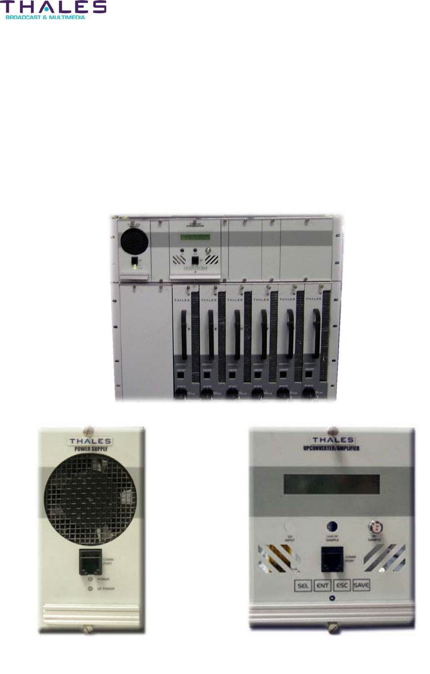
The Affinity® L-Band solid-state low power transmitter is available in several models providing
output powers ranging from 50 to 400 Watts average (rms). The transmitter brand can house up
to sixteen high-gain full-band GaAs FET amplifier modules operating in parallel. The quantity of
amplifiers installed for a system is determined by the desired output power.
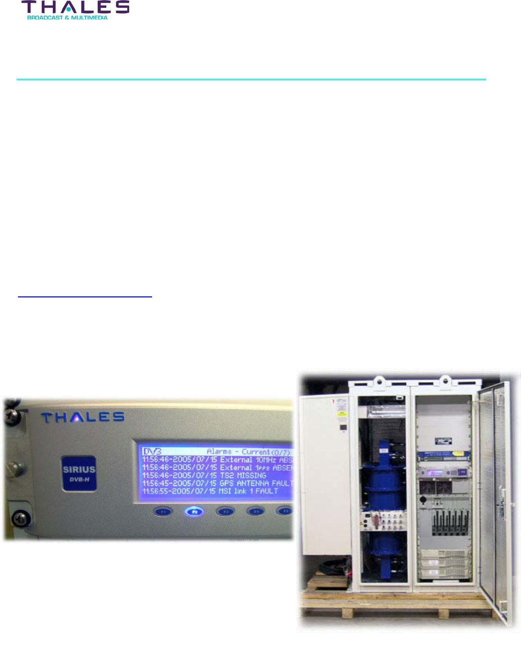
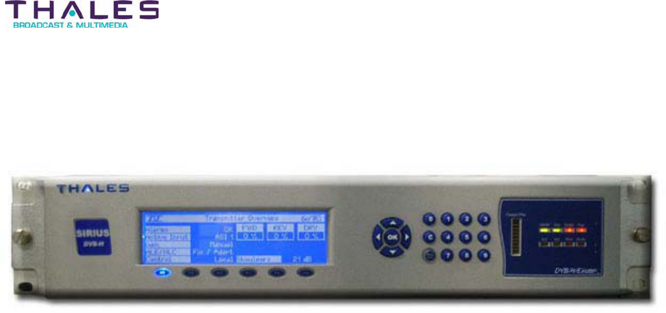
Each Affinity® transmitter is provided with a DVB-H RF Sirius Exciter containing linearization
circuits to compensate for both linear and non-linear distortions. The correction can be operated
in an adaptive mode allowing automatic compensation and signal optimization.
The Affinity® family of solid-state low power transmitters includes an advanced control system
providing enhanced monitoring and diagnostic capability. The single or dual drive configuration
determines the operating interface for the system.
For single drive (SD) configurations, the front panel of the DVB-H RF Sirius Exciter includes a
Local Control & Monitoring Panel (LCMP) with a man-machine interface (MMI). The MMI
consists of a front panel Liquid Crystal Display (LCD) and a soft-key activated menu that
provides transmitter controls, power readings and alarm indicators.
For dual drive (DD) operation, each of the DVB-H RF Sirius Exciter units are controlled by an
external Central Processing Unit (CPU) that includes switchover management for a Web server
or SNMP agent. The LCMP for dual drive operation consists of a color touch screen with menus
and bar graph.
Remote operation for both configurations can be made by either an embedded Web server
through a standard browser, or through a SNMP agent by means of an SNMP manager.

Features - 8 -
®
Affinity LBD-200C-N1 Transmitter
Product Manual
4.2 Affinity® Low Power Transmitter Configurations
There are three basic transmitter configurations available:
Single Drive – One exciter/driver chain drives the power amplifiers in parallel. This configuration
includes options for N+1 power supply.
Dual Drive – Two exciter/driver(s) operating in a main/standby automatic switching mode drives
the power amplifiers in parallel. This configuration includes options for N+1 power supply.
Diversity Transmitter – This configuration can feed four antennas in 90osectors. There are two
independent single drive transmit chains fed by a common exciter with embedded time delays
on each output. The exciter time delay function is defined in the DVB-H standard, EN 300744.
The delay must be within the guard interval defined in the network, and should add a few
microseconds of delay in relation to the other transmitter in the site. The timing information can
be sent to the transmitter via the Megaframe Information Protocol (MIP) or can be adjusted
locally in the modulator.
4.3 Affinity® Family Construction
The Affinity® family of low power solid-state DTV transmitters is designed to provide maximum
flexibility for site layout and installation. All of the transmitter chassis are designed to fit in EIA
standard 19” wide equipment cabinets. Outdoor installations are equipped with high quality front
and rear access enclosures. These enclosures maintain security and protection against external
elements. Transmitter systems are available in several configurations based on output power,
redundancy options, and site system requirements.
Single channel, non-redundant transmitter configurations (SD) are sized as follows:
For 50 to 125 watt average output power levels, the upconverter and amplifier are self-
contained in a single 6 rack unit (RU) chassis. The N+1 capable power supply is housed
in a 3RU chassis, and the Thales DVB- T/H RF exciter is contained in a 2RU chassis.
This 11RU transmitter is the most compact Thales Affinity system.
x
x
x
For 200 watts average output power levels, three chassis are used (14RU total). The
upconverter assembly is self-contained in a single 3RU chassis. The power amplifiers
are housed in a 6RU chassis. The N+ 1 capable power supply is housed in a 3RU
chassis and the Thales DVB- T/H RF exciter is housed in a 2RU chassis.
For 400 watts average output power levels, four chassis are used (20RU total). The
upconverter assembly is self-contained in a single 3RU chassis. The power amplifiers
are housed in two 6RU chassis. The N+1 capable power supply is housed in a 3RU
chassis and the Thales DVB- T/H RF exciter is housed in a 2RU chassis.
A dual drive transmitter operating in main/standby configuration (DD) is sized as follows:
The Thales DVB-H RF exciter is contained in a19” 9RU chassis that includes: 2RU chassis for
the DVB-H RF exciters, 3RU chassis that house the CPU board with PSU, the DVB-H RF
Exciter/Up Converter, and the amplifiers interface board. 1RU is used for the fan unit and air
inlet, and 1RU for the dedicated front panel that supports the touch screen and bar graph.
Features - 9 -
®
Affinity LBD-200C-N1 Transmitter
Product Manual
The transmitter uses self-contained ambient forced air-cooling (front to back airflow). All fans
are internal to the chassis. Refer to the Cabinet Air Conditioning section of this manual for
additional details of the LBD-200C-N1 transmitter cooling and environmental control systems.
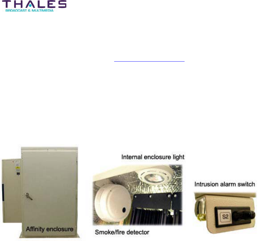
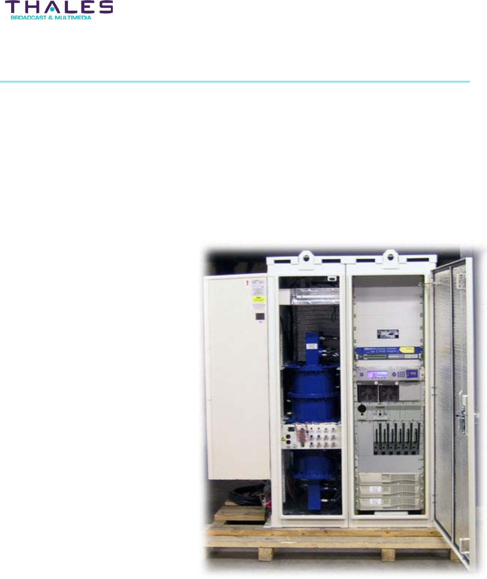
The transmitter system including all ancillary equipment is housed in a Nema 3R rated
enclosure with approximate dimensions: 74” H x 44” W x 44” D. This self-contained unit features
eyelets for lifting the entire assembly during installation. The base has mounting provisions for
mechanical and electrical attachments to building structures. Equipment access is achieved
through front and rear opening doors fitted with locks and intrusion alarms with remote
signaling. Internal enclosure lights illuminate when any door is opened during maintenance. A
smoke/fire detector with remote signaling is utilized to provide the earliest warning of
catastrophic failure caused by a natural occurrence or other means.
Located inside the enclosure is an EIA standard 19” rail structure system used for rack
mounting each sub system contained in the Affinity® configuration.
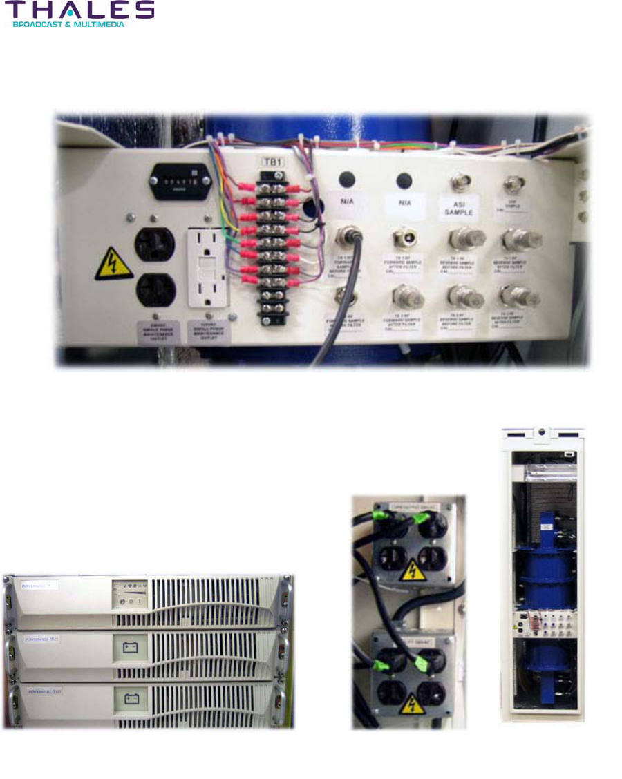
The AC distribution system is comprised of: 120/230VAC surge suppression with alarms, two
230VAC outlets, and two 120VAC outlets with separate circuit protection. Four 230VAC utility
outlets are provided along with four UPS protected outlets located along the rear corner of the
enclosure. These outlets are intended to connect transmitter ancillary equipment. An external
disconnect box allows connection of a portable generator. An AC hour-meter will record the
operational hours of the equipment.
A UPS is employed to keep critical subsystems running in instances of temporary AC power
loss. The 230VAC UPS output is capable of 700VA/490W. Storage for the UPS is via two
24VDC extended battery modules capable of providing an output of approximately 210 Watts for
400 Minutes (6.9 Hrs). This power is intentionally distributed to the site management system,
satellite receiver, and DVB-T/H RF exciter to enable status communications from the site, back
to the operations center, to continue while normal operating site power is absent. Having the
exciter and satellite receiver powered up also minimizes transmitter restart times once normal
site power has been restored.
Features - 10 -
®
Affinity LBD-200C-N1 Transmitter
Product Manual
AC Distribution System Panel with AC Hour Meter and IF and RF Sample points
UPS System UPS & Utility outlets
(rear side of cabinet)
Bandpass filter
A bandpass filter with integrated RF probes provides the filtering required to comply with FCC
specifications and to achieve high-level out-of-band emission compliance. A circulator, with
load, also an integral part of the RF system, is mounted internally to the cabinet.
A two side-mounted air conditioner unit will provide environmental stabilization for the
transmitting system. A temperature sensor with remote signaling monitors and reports out of
tolerance internal operating temperatures. Weatherproof coax and AC entry ports located on the
side of the cabinet provide for easy access during installation. Critical IF and RF sample points

Features - 11 -
®
Affinity LBD-200C-N1 Transmitter
Product Manual
used for monitoring and troubleshooting are accessible internally from the front-side of the
cabinet. All service and external interface points are easily accessible through the front, rear
and left side of the cabinet. The right side of the cabinet is intentionally left blank for installation
near a build wall or similar structure. Most field replacement units are front-loaded. Each cabinet
assembly is designed to fit through typical building service entries requiring no major structural
changes for installation. An optional rain shield can be provided to aid in protection against a
sudden change of weather during maintenance; however for safety reasons maintenance in
poor weather is not suggested nor recommended by Thales. Refer to the cabinet layout
diagrams in the Block Diagram and Schematics section of this manual for further detail.
The modulator supports 2k, 4k & 8k operating modes, and is well suited for Multi Frequency
Networks (MFN), Single Frequency Networks (SFN), and Hierarchical operation. The modulator
has been seamlessly integrated as part of the Affinity® transmitter
Each Affinity® L-Band transmitter incorporates GaAs amplifier architecture.The Affinity®
transmitter is integrated with the most advanced heat sink technology, and the integral forced
air-cooling system of the Affinity® virtually eliminates the need for external blower units. The
Affinity® line of transmitters are fully compatible with DVB-H standards and feature advanced
embedded software for alignment and system management.
4.4 Additional Affinity® Features:
Advanced embedded microcontroller design; all transmitter performance adjustments
are programmable and password controlled.
x
x
x
x
x
x
x
x
x
x
x
No mechanical tuning required.
Software setup and control via front panel RS-232 communication ports and/or Local
MMI.
Built-in RS-485 network hardware used to interface control and monitor systems.
SNMP, Web Server, etc.
Built-in diagnostics with front panel Liquid Crystal Display (LCD) status display.
Controlled fold-back VSWR protection. Fast shutdown under extreme reflections.
Soft fold-back of output power under Power Amplifier Segment (PAS) fault conditions.
Modular front panel plug-in design for easy maintenance and repair.
Field Replaceable Unit (FRU) modules are common among the different power levels.
Incorporated “Hot Swap” solid-state final power amplifier architecture
The Affinity® includes an advanced control system that provides for enhanced monitoring and
diagnostic capability. The control system includes a screen-display for detecting and locating
equipment malfunctions and faulty subassemblies. The control system interface consists of a
front panel LCD and a soft-key activated menu. Alarm indicators and normal controls, as well as
power readouts, are available via the display assembly.
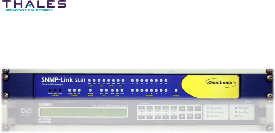
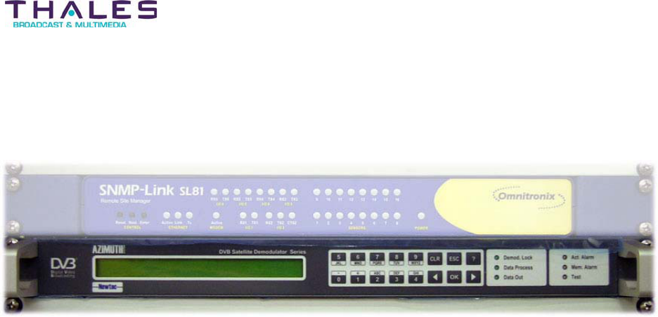
The Affinity® transmitter incorporates the Omnitronix SL81 Status Control and Monitoring
Systems (SCMS). (See SCMS section of this manual for operational details.)

Specifications - 12 -
®
Affinity LBD-200C-N1 Transmitter
Product Manual
5 Specifications
5.1 Affinity® LBD-200C-N1 Transmitter Specifications
Parameter Specification Test Conditions/ Notes
Transmitter Output
Average Output Power at the
transmitter output (using RF probe
to sample main output; N-
connector)
54.5 dBm in application with channel
filter
1. Thermal power sensor is
recommended to verify average
output power.
2. Modulated carrier
3. UHF input frequency 670 – 675
MHz
4. UHF input power –18dBm ±3dB
5. UHF input waveform COFDM
DVB-H
6. ALC – ON, AGC – ON
7. Linearization – ON
Average Output Power at the
channel filter output (using RF
probe to sample main output; N-
connector)
53 dBm assuming 1.5 dB insertion loss
of the circulator, channel filter, RF
probes and jumper cables
1. Thermal power sensor is
recommended to verify average
output power.
2. Modulated carrier
3. UHF input frequency 670 – 675
MHz
4. UHF input power –18dBm ±3dB
5. UHF input waveform COFDM
DVB-H
6. ALC – ON, AGC – ON
7. Linearization – ON
Out of band Intermodulation
Products / Adjacent Channel
Interference
FCC spectral mask definition for the
1670-1675MHz band per FCC
Document 47, Telecommunications:
Part 27, Miscellaneous Wireless
Communications Services:
Section 53, Emissions Limits. Subparts
(i), (a) (4)
Sidelobe power spectral density (PSD)
across 1MHz shall be attenuated below
the TX (PSD) power (P) by 43+10log
(P)
Spectral Mask must be measured at
the output of the channel filter.
TX input has to exceed FCC spectral
mask definition if OEM exciter is used.
For TX compliance shoulder level
typically should be better than 50dB at
breakpoint w/ minimum of 8db non-
linear correction capability.
1. Thermal power sensor is
recommended to verify average
output power. Emissions
measured with spectrum analyzer
or VSA RBW=30kHz VBW=
100Hz
2. Modulated carrier
3. UHF in
p
ut fre
q
uenc
y
670
–
675

Specifications - 13 -
®
Affinity LBD-200C-N1 Transmitter
Product Manual
Parameter Specification Test Conditions/ Notes
MHz
4. UHF input power –18dBm ±3dB
5. UHF input waveform COFDM
DVB-H
6. ALC – ON, AGC – ON
7. 7. Linearization – ON
Out of band Intermodulation prior to
channel filter
Per spectral mask defined as:
Lower
Channel edge falls between 1670-
1670.122875 MHz
Shoulder at 1669.822975 MHz and
lower must bed -32 dBc
Upper
Channel edge falls between
1674.877125-1675 MHz
Shoulder at 1675.177125 MHz and
above must bed -32 dBc
TX input has to exceed FCC spectral
mask definition, if OEM exciter used,
in order for TX compliance shoulder
level typically should be better than
50dB at breakpoint w/ minimum of 8db
non-linear correction capability.
1. Thermal power sensor is
recommended to verify average
output power. Emissions
measured with spectrum analyzer
or VSA RBW=30kHz VBW=
100Hz
2. One modulated carrier
3. UHF input frequency 670 – 675
MHz
4. UHF input power –18dBm ±3dB
5. UHF input waveform COFDM
DVB-H
6. ALC – ON, AGC – ON
7. Linearization – ON
Inband Intermodulation
Intermodulation products shall not
exceed –30dB when comparing portion
of the mean power spectral density of
the wanted COFDM signal relative to
the same portion when “n”-number of
carriers are switched off. Sampled
bandwidth not to exceed bandwidth of
carriers removed.
Modulator must have facility to switch
off a block of carriers within the
COFDM signal and have better than –
33dB IM when same test is conducted
at input.
1. Thermal power sensor is
recommended to verify average
output power.
2. One modulated carrier
3. UHF input frequency 670 – 675
MHz
4. UHF input power –18dBm ±3dB
5. UHF input waveform COFDM
DVB-H
6. ALC – ON, AGC – ON
7. Linearization – ON
Transmitter Frequency Response,
fixed 5 MHz channel
Relative to the level at ƒcenter shall not
deviate by more than +/-0.5dB across
the frequency range ƒcenter –2.4MHz
to ƒcenter +2.4MHz.
Frequency response is measured at
the output of the channel filter. Test is
done using spectrum analyzer with
modulated input waveform and:
1. UHF input frequency 670 – 675
MHz

Specifications - 14 -
®
Affinity LBD-200C-N1 Transmitter
Product Manual
Parameter Specification Test Conditions/ Notes
MHz
2. UHF input power –18dBm ±3dB
3. UHF input waveform COFDM
DVB-H
4. ALC – ON, AGC – ON (if
spectrum analyzer or VSA is
used; both OFF if network
analyzer method is used)
5. Linearization – ON
Transmitter Group Delay, fixed
channel, 5 MHz wide
Over the frequency range ƒcenter –
2.4MHz to ƒcenter +2.4MHz shall not
exceed +/-200nS relative to the delay at
ƒcenter
Group Delay is measured at the output
of the channel filter. Test is done using
network analyzer broadband detection
from UHF input to channel filter output.
Modulator must compensate +/-100 ns
of delay and:
1. UHF input frequency 670 – 675
MHz
2. UHF input power –18dBm ±3dB
3. IF input waveform COFDM DVB-
H
4. ALC – OFF, AGC – OFF
5. Linearization – ON
Transmitter Carrier to Noise (C/N) t 55 dB
C/N is measured at the transmitter
output (no channel filter).
RF Output power, 5 MHz channel,
measurement conditions
1. UHF input frequency 670 – 675
MHz
2. UHF input power –18dBm ±3dB
3. IF input waveform COFDM DVB-
H
4. ALC – OFF, AGC – OFF
5. Linearization – ON
Thermal Noise Power is measured at
5MHz BW at the channel center
frequency.
Measurement is done with Spectrum
Analyzer or VSA using PSD.
Spurious Products
(Undesired signal power 2 dB
higher than the nominal PSD of the
adjacent spectral regions that is
harmonically related to
unmodulated carrier)
d -60 dBc
Relative to nominal modulated power
measured @ 100 kHz RBW at the
channel filter output.

Specifications - 15 -
®
Affinity LBD-200C-N1 Transmitter
Product Manual
Parameter Specification Test Conditions/ Notes
Harmonics
(Undesired signal power 2 dB
higher than the nominal PSD of the
adjacent spectral regions that is
harmonically related to
unmodulated carrier)
d -60 dBc
Relative to nominal modulated power
measured @ 100 kHz RBW at the
channel filter output.
Output Frequency Single channel, factory selected at
1670-1675MHz, 5 MHz wide
Output Spectrum Orientation Non-Inverted
Output Impedance Output Return
Loss 50 : 15 dB
Measurement of the output return loss
at the N connector of transmitter with
all amplifiers connected and turned on.
From 1670-1675MHz
RF Output Regulation dr 0.3 dB
Measured at transmitter output at
nominal output power and:
1. UHF input frequency 670 – 675
MHz
2. UHF input power –18dBm ±3dB
3. UHF input waveform COFDM
DVB-H
4. ALC – ON, AGC – ON
5. Linearization – ON
RF output regulation is defined as
regulation vs. temperature.
Hum and Noise d -60 dBc
Test of power supply DC output under
full load measurement by ratio of RMS
hum or noise to the corresponding DC
voltage
MER t 30 dB
Measurement at nominal output power
COFDM DVB-H, Measured at channel
filter output
MER = 20 log (EVM/100)
Error Vector Magnitude (EVM) d 3.16%
Measurement at nominal output power
COFDM DVB-H, Measured at channel
filter output
Transmitter Output MUTE
Loss of lock of the local oscillator
Loss of input signal
User force to standby condition
Transmission shutdown when the SFN
timing is out of limits
Transmission shutdown when wrong
region program is applied to the
Modulator.
Transmission shutdown when
Transmission start-up when any of the
conditions are cleared

Specifications - 16 -
®
Affinity LBD-200C-N1 Transmitter
Product Manual
Parameter Specification Test Conditions/ Notes
equipment temperature or RF reverse
power limits are severely exceeded
Transmitter start up time
From Cold or long AC absence
From Standby
From Reset
< 10 seconds
< 7 seconds
< 7 seconds
Time measure; from AC application to
RF output enabled and at nominal
output power.
Single frequency network timing
The transmission timing of each
Transmitter site with respect to all
others in the network controlled to
within a tolerance of 300nS
Parameter Specification Notes / Test Conditions
Exciter
Transmission Characteristics
Emission standard: DVB-H
Modulation scheme: COFDM
Bandwidth: 5, 6, 7, or 8 MHz
Environmental and Safety
Guaranteed performance: 0o to 45o up
to 3000m
Safety: IEC215, IEC1010
Acoustic noise: IEC 179: <65dBa
General Mechanical Rack: 19” 2U, depth 450mm
Cooling: 4 internal fans, front to rear
Input Power
Voltage: 230V/105V ±15%
Frequency: 47-63 Hz
Consumption: <200VA
Transport Stream Input Dual A and B ASI inputs
RF Output
Standard: DVB-H
Power: 0 dBm
Output connector: 50ohm, BNC
Frequency: agile between 40-862 MHz
Intrinsic Signal Quality
Global MER: >38dB
MER per carrier: >38dB
EVM on each carrier: < 1%
BER before Viterbi: < 1x10⁻⁶
END: <0.1 dB
In band frequency response: < ± 0.2dB
Group delay ripple: < ± 10ns
Intrinsic Out of band Emissions
Shoulders at ± 500kHz: > 46dB
Shoulders at ± 10 MHz: > 50dB
Spurious < 1GHz: >50dB
Transmission Characteristics Emission standard: DVB-H

Specifications - 17 -
®
Affinity LBD-200C-N1 Transmitter
Product Manual
Modulation scheme: COFDM
Bandwidth: 5, 6, 7, or 8 MHz
LO Frequency 1000MHz Main LO used to convert UHF to
Microwave channel
LO Frequency Stability
All conditions
Without GPS drift correction:
dr1 part in 1010 over any one-year
period without adjustment.
With GPS drift correction:
dr5 parts in 107 over any one-year
period without adjustment.
LO power +5dBm, r 3 dB Direct measurement of microwave LO
LO Harmonics -20 dBc Measured at the LO TP
Non-Harmonic Spurious
100Hz < ƒoffset < 10KHz, -70dBc
10KHz < ƒoffset < 20MHz, -60dBc
Other < –65dBc
Measured at the LO TP
LO Warm-up time 5min for frequency accuracy of dr5
parts in 108
Aging 1 day r1 parts in 109
1year r2 parts in 107
SSB Phase Noise
d55 dBc/Hz @ 10Hz offset
d85 dBc/Hz @ 100Hz offset
d85 dBc/Hz @ 1 KHz offset
d105 dBc/Hz @ 10 KHz offset
d112 dBc/Hz @ 100 KHz offset
d130 dBc/Hz @ 1MHz offset
Direct measurement of microwave
carrier set to CW tone.
Frequency Reference input 0 dBm r 5 dB (+48 dBmV) r 5 dB
Input Return Loss 18dB Measure at the IF input connector
Frequency Reference Connector BNC-female
Frequency Reference Impedance 50:
Parameter Specification Notes / Test Conditions
Upconverter Amplifier INPUT
UHF Input Frequency 670.000-675.000 MHz (5 MHz BW)
If OEM exciter used, Input frequency
has to be within acceptable tolerance
to fulfill output frequency stability
requirements prescribed by FCC.
UHF Input Frequency stability
With GPS drift correction:
dr1 part in 1010 over any one-year
period without adjustment.
Without GPS drift correction:
dr5 parts in 107 over any one-year
period without adjustment.
Input frequency has to be within
r1kHz window to fulfill output
frequency stability requirements
prescribed by FCC Section 2.1055 (a)
(1) / 73.687 / 21.101 (a)

Specifications - 18 -
®
Affinity LBD-200C-N1 Transmitter
Product Manual
Nominal Input Power, Average -18dBm
188 Thermal power sensor is
recommended to verify
average input power. Or PSD
method
2. UHF waveform COFDM DVB-H
Input Power variation
All conditions r 3 dB from nominal input power
IF input Survivable Power,
NO DAMAGE 10 dBm AGC and ALC on; input level at 0dBm
Spectral Mask of the input signal Exceed FCC spectral mask definition
for the 1670-1675MHz band
Input Return Loss 10dB Measure at the IF input connector
Input Impedance 50 :
UHF Input Connector BNC-female
Parameter Specification Notes / Test Conditions
Front Panel Alarms/Indicators/Adjustments/Controls
Front panel display, System
forward output power
Relative output power (%) calibrated
against absolute output power (dBm)
Max. error 0.2 dB within 1.5 dB
window from nominal output power;
LCD display
Front panel display, reflected
output power
Relative reverse power (%) calibrated
against absolute output power (dBm)
100% at TX set to nominal output
power and SHORTED output (N
connector)
0% at nominal output power and 50
Ohm (16 dB return loss) load at the
transmitter output (N connector); LCD
display
Front panel display, upconverter
forward output power
Relative output power (%) calibrated
against absolute output power (dBm)
Max. error 1.0 dB within 1.5 dB
window from nominal output power;
LCD display
Front panel Diagnostics LCD Displays with menu keys
LED display for power supplies
Module Control Interface
RS232 serial communications
protocol
Interface Connector
Front Panel RS232 port(s)
TNET Thales proprietary
RJ11 connector
Connector located on each plug-in
front panel
Parameters defined in plug-in level
specs
Refer to document # 47267228-306
Upconverter plug-in spec
Refer to document # 47266099.00-
306 Power Supply plug-in spec
Rear Panel Diagnostics Interface
Electrical Interface Logic 0 for fault signals, 12V at 100mA,
Reset and stand-by Amplifiers
Diagnostics Interface connector Terminal block J1 connector of rear panel

Specifications - 19 -
®
Affinity LBD-200C-N1 Transmitter
Product Manual
Rear Panel Remote Serial Monitoring and Control Interface
Serial Network Communications
Protocol TNET Thales proprietary
Electrical Interface RS485 4-wire full duplex (remote bus) Daisy chain connection, last device in
chain requires termination
Interface Connectors (2) RJ11 connectors NET interface on rear panel
Rear Panel Local Serial Monitoring and Control Interface
Serial Network Communications
Protocol TNET Thales proprietary
Electrical Interface RS485 4-wire full duplex (local bus)
Interface Connector RJ11 connector J3 connector of rear panel
Rear Panel Agile controller interface
Electrical Interface TTL logic
Provides critical TX status and
controls for use with Thales agile
back-up and control system (ABCS),
for N+1 system configurations
Interface Connector RJ11 connector J2 connector of rear panel
Rear Panel ABCS interface
Electrical Interface TTL logic
Interface Connector Male 15-pin D-sub connector
J4 connector of rear panel; used for
ABCS command of the designated
Agile UCA unit.
Rear Panel modulator interface
Serial Network Communications
Protocol
OPT 1 Thales proprietary
OPT 2 UBS/ProTel proprietary
Used to interface TX to Thales or
OEM (UBS/Protel) Modulator; offers
limited command and status of OEM
modulator.
Electrical Interface RS232 2-wire full duplex
Interface Connector Male 9-pin D-sub connector J6 connector of rear panel
Rear Panel PAS Command
Serial Network Communications
Protocol TNET Thales proprietary
Electrical Interface RS485 4-wire full duplex (local bus) +
PAS standby & reset
Interface Connector Female 9-pin D-sub connector J7 connector of rear panel

Specifications - 20 -
®
Affinity LBD-200C-N1 Transmitter
Product Manual
Rear Panel LAN interface (Optional)
Serial Network Communications
Protocol SNMP / TCIP
Electrical Interface Ethernet
Interface Connector RJ45 connector J5 connector of rear panel
Parameter Specification Notes / Test Conditions
General
Power Requirement
Supply Voltage (VAC)
Consumption (kW)
Power factor (kW/kVA)
Cos Ø
220 VAC +10% -15%; 50/60 Hz;
<8.4kW
.9
AC connector
Cabinet
Internal
Terminal Block
IEC 320 with locking clamp or terminal
block
Acoustic Noise
Outside cabinet
Inside cabinet
Measured at 1 m from cabinet al
directions with air conditioner at noisiest
operation cycle
Measured?
Environmental
System Operating Temperature -15qC to +40qC
Transmitter enclosed in environmentally
controlled shelter. Frequency stability
and equipment functionality guaranteed
System Specified Temperature
Range +5q to +40qC
Transmitter enclosed in environmentally
controlled shelter. All Specified
parameters guaranteed.
Transmitter Specified Temperature
Range +13q to +33qCNo environmental controls
Relative Humidity 98% non-condensing No environmental controls
Physical
Dimensions 74” H x 44” W x 44” D
188 cm H x 111.8 cm W x 111.8 cm D
Approximate Shipping Weight Fully loaded

Specifications - 21 -
®
Affinity LBD-200C-N1 Transmitter
Product Manual
Agency Compliance
Regulatory Title 47 Part 27.53 of the FCC rules
FCC ID CHPLBD-25200 Pending
Standards ETSI EN 300 744 V1.5.2: DVB-
T/DVB-H specification, 21 Jan
2004(draft specification) TS 101
191 V1.3.1: SFN Synchronization
EN 300 468: SI Specification ETR
211(SI Guidelines), ETR 162,
ISO/IEC 13818, ETR 154, EN 301
192, TR 101 202: documents
concerning the Services and data
signalization for DVB-T/DVB-H.
DVB A010: Interface for
CATV/SMATV Head End and
Similar Professional Equipment.
TM1449 ETR 190: Guide Line for
DVB-T/DVB-H networks
Safety Meets UL1950/CSA950C22.2-M95
listed specifications
Official certification at Thales
discretion
Power Consumption
Element Power consumption
(All stated values assume
full rated transmitter output
and air conditioner
operating)
Power factor Load current analysis
(Showing the amplitude
of the fundamental and
harmonic currents)
Satellite RX 100 VA >.9
Remultiplexer 100 VA >.9
DVB-H Exciter w/GPS 200 VA >.9
Upconverter Amplifier
200W
3800 VA .95 typical
Site management system 100 VA
AC unit (Air Conditioners)
200W 4025 VA
Total system
200W 8325 VA .95 typical

Specifications - 22 -
®
Affinity LBD-200C-N1 Transmitter
Product Manual
RF Performance:
Modulation Standard DVB-T/DVB-H
Average Output Power 50, 100, 200, & 400 Watts
Output Frequency 1670-1675 MHz
Input Interface MPEG2 Dual ASI, 75 Ohms BNC female Connector
Output Connector 50, 100, and 200 watts – N female
400 watts – 7/16 DIN female
User interface 7/16DIN female (all cases)
Output Impedance 50 Ohms
Frequency Response r0.5 dB
Frequency Stability r150 Hz 30 days (internal reference)
r1 Hz (Optional External GPS)
Carrier to Noise (C/N) 55 dB
Hum and Noise -60 dBc
Group Delay r200 ns
Out-of-band Emissions Compliant with FCC Document 47, Telecommunications: Part
27, Miscellaneous Wireless Communications Services:
Section 53, Emissions Limits. Subparts (i), (a) (4)
Harmonics d -60 dBc
MER t 30 dB
RF Output Regulation dr .2 dB
Electrical Requirements:
Power Requirement (200 watts) Single Phase, 220 VAC +10% -15%;
Frequency 50/60 Hz
Consumption including ADAPT exciter
(does not include encoding / multiplexing
equipment, Starter PAK listed below for
reference)
200 watts 4350 VA
Heat loading including ADAPT exciter
(does not include encoding / multiplexing
equipment, Starter PAK listed below for
reference)
200 watts 3.42 kW
“ancillaries” consumption / heat loading 500 VA / 550 watts
Power Factor Correction Typical 0.95, minimum 0.9

Specifications - 23 -
®
Affinity LBD-200C-N1 Transmitter
Product Manual
Ambient Environment:
Operating Temperature +32qF to +122qF (0qC to +50qC)
Specified Temperature Range +55qF to +91qF (+13q to +33qC)
Relative Humidity 95% non-condensing
Power Amplifier Cooling Forced ambient air, front to back flow using integral high
volume fans
Mechanical:
Cabinet Dimensions 74.0” H x 44” W x 44” D
188 cm H x 111.8 cm W x 111.8 cm D
Weight Dependent on transmitter configuration, consult factory
Color Customer specified
Transmitter Service Rear and Front
Access Rear and Front
Specifications - 24 -
®
Affinity LBD-200C-N1 Transmitter
Product Manual
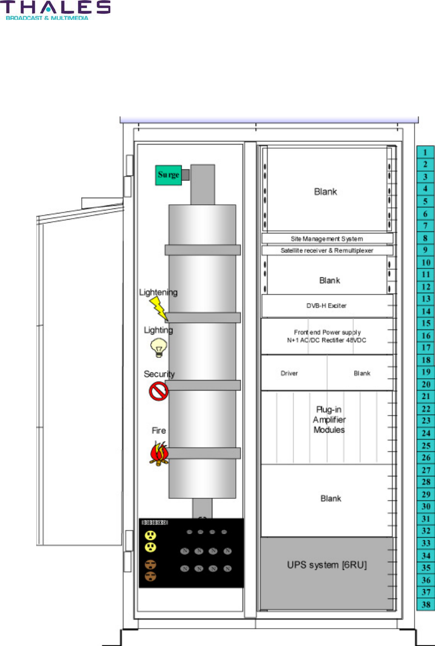
5.2 Affinity® LBD-200C-N1 Cabinet Layout
Specifications - 25 -
Affinity® LBD-200C-N1 Transmitter
Product Manual
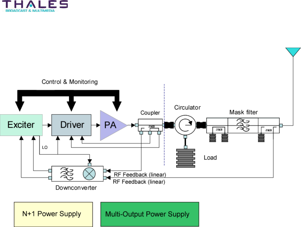
Simplified Transmitter Block Diagram

Specifications - 26 -
®
Affinity LBD-200C-N1 Transmitter
Product Manual
5.3 Affinity® LBD-200C-N1 FRU Part Numbers
This section lists the modular Field Replacement Units (FRU) of the Affinity® unit. Complete
parts lists are included at the end of this manual.
453313-01 Affinity® LBD-200C-N1 Transmitter
Item Part Number Qty Description
754578-01 1 Receiver, Satellite
754580-01 1 Site Management System, SNMP Link
47267295 1 Chassis Assembly, 3RU Driver L-Band
47267352 1 Chassis Assembly, 6RU 6-Amp L-Band
754573-01 1 Filter, Spectral Mask
47267381.01 1 Sirius DVB-H Modulator w/Keypad, GPS
754568-01* 2 Front-End Power Supply Assembly
*Assembly 47266865.07 includes a rack and
two Front-End Power Supplies
47267228.01 1 Upconverter L-Band (Driver Component)
47266099.04 1 Power Supply Plug-In (Driver Component)
47267227.01 6 Amplifier Assembly, L-Band
47267339 1 Downconverter, L-Band UHF
751338-01 2 Attenuator, 17dB 50 Ohm SMA
752732-01 2 Attenuator, DC to 2GHz 3dB 2W
754572-01 1 Circulator, 500W “N”
607270-01 2 Load, 500W Air Cooled
400279-08-48 4 Required Cable Assembly, Coax
400279-09-48 1 Required Cable Assembly, Coax
400279-10-48 4 Required Cable Assembly, Coax
400279-28-48 1 Required Cable Assembly, Coax
400279-35-48 2 Required Cable Assembly, Coax
410920-01-48 2 Required Cable Assembly, Video
609125-01 2 Cable, LMR600 5’L 7/16Din-“N”
609124-01 2 Cable, LMR600 3’L 7/16Din M
609123-01 1 Cable, Flat Mod RJ11/Spade Lug
607618-01 4 Cable, Ethernet CAT5
607883-01 2 Cable Assembly, DB9-M to F STR 2’
47267403 1 Cable Assy, Alarm DB9M-Open End
47267404 1 Harness Assy, 6P Molex to Ring
Specifications - 27 -
®
Affinity LBD-200C-N1 Transmitter
Product Manual
5.4 Fusing and Protection
Fusing:
Location Reference Value Thales P/N
Power Supply
Rear Panel
AC Fuse 4-Amp fuse 752785-01
PA Power Switch Circuit Breakers
(magnetic) Qty-4
40-Amp 754253-01
PA Fan Circuit Breakers (thermal) Qty-2 1-Amp 754383-01
Sub-Chassis fuse locations
Controls and Indicators:
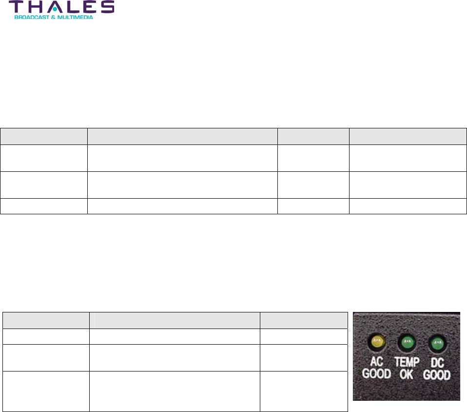
The OEM Front-End Power Supply contains the following indicators:
Description Signal LED Indicator
AC Good A lit LED indicates AC is present Amber
Temp OK A lit LED indicates DC output is
operating within tolerance
Green
DC Good A lit LED indicates temperature
inside the power supply is within the
operating temperature range
Green
Thermal Protection:
Certain plug-in modules are thermally protected with over-temperature sensors. If temperatures
exceed 122º Fahrenheit (45º Celsius), the plug-in module is shut down by the microprocessor
until the temperature is below the trip-point level.
Interlocks:
Interlocks are performed through the software applications.
VSWR Protection:
The Voltage Standing Wave Ratio (VSWR) protection system will lower the transmitter output
power by 6dB if the reflected power exceeds 16%, of the transmitter output power (calibrated on
a 100% scale). If the reflected power reaches 25% of the transmitter output power, the VSWR
protection system shuts the transmitter down. To bring the transmitter back into operation after
a VSWR protection shutdown requires an operator to perform a transmitter reset through the
Omnitronix SL-81 Site Management system, local reset via MMI on front panel, or by cycling the
Upconverter Module power.

Specifications - 28 -
®
Affinity LBD-200C-N1 Transmitter
Product Manual
5.5 Equipment Packaging
The transmitter is packaged at the factory on a single skid. Assemblies to be
mounted in the transmitter are packed in crates. The skid and crates may contain
one or more precaution labels or markings. These markings provide information
regarding the various precautions that should be observed during the handling,
unpacking, and storage of the equipment crate. Examples of these precautions may
include positioning, fragility, and weather constraint labels.
NOTE: Acceptable storage climate for the equipment crate is between -30ºC to +60ºC.
5.5.1 Unpacking and Inspection
Before taking delivery, and prior to removing the contents of the crates, examine the exterior of
the crates for evidence of shipping damage. If any damage is visible to the crate or the contents,
do not continue to unpack the equipment. Protect the goods from further damage and contact
the freight carrier and Thales immediately for further instructions.
If the crate is free from damage, the equipment may be carefully removed. The following tools
are recommended for the unpacking process:
x Cutter
x Screwdriver
Remove the packing slip from the cover of the crate. Using the screwdriver, remove the top
cover and one of the sides of the shipping crate. With the cutter, carefully cut through the cover
material. Be careful not to damage any equipment during this process.
Once the equipment has been removed from the crate and verified against the packing slip,
inspect the equipment for any signs of damage. If any damage is visible, contact Thales
immediately for further instructions. While unpacking, carefully compare packing list with the
equipment, checking for in-transit damage at the same time. Should any damage be noted,
notify the freight carrier at once to file a freight claim. Do not discard any packing material until
told to do so by the carrier. Also, notify Thales Broadcast & Multimedia of any damages or
missing materials from the shipment. Retain original boxes and internal packing materials to
adequately protect equipment to be returned to the factory for repairs, upgrades, or
modifications.
5.6 Environment Considerations
The equipment housed in outdoor enclosures can be safely operated in ambient temperatures
of -15º to +45º Celsius (5º to +113º Fahrenheit) The RF power regulation and frequency
determining devices are qualified to operate across -30 to +50º Celsius (-22º to +122º
Fahrenheit) However, the channel filter will tolerate much less temperature variation. Therefore,
if not installed in a qualified outdoor enclosure with HVAC system, Thales recommends that the
transmitter be operated within r10q Celsius from room ambient. Moderate temperatures
generally extend equipment life. Although the equipment may be operated with relative humidity
Specifications - 29 -
®
Affinity LBD-200C-N1 Transmitter
Product Manual
of up to 95%, the equipment must be protected from conditions that cause condensation within
the equipment. The transmitter chassis requires a rack with a minimum of 24” vertical front-to-
rear rail separation. If a rear door must be used to secure the rack cabinet, the rack must be at
least 40” deep to accommodate transmitter cabling, and the door must open fully or be removed
to allow transmitter maintenance. If a rear door is placed on the rack, forced ventilation through
the cabinet is required (600 cfm minimum per transmitter is recommended) and an air or
temperature interlock should be incorporated for protection against interruption of ventilation
(contact Thales Broadcast & Multimedia Customer Service department for assistance). In case
of indoor installations, the area should be kept dry and clean. There should be sufficient space
in front of the transmitter cabinet for service personnel and test equipment. A minimum of 44”
behind the cabinet should be free for rear cabinet access and air movement. Also, ample room
must be available at the cabinet rear for cable placement.
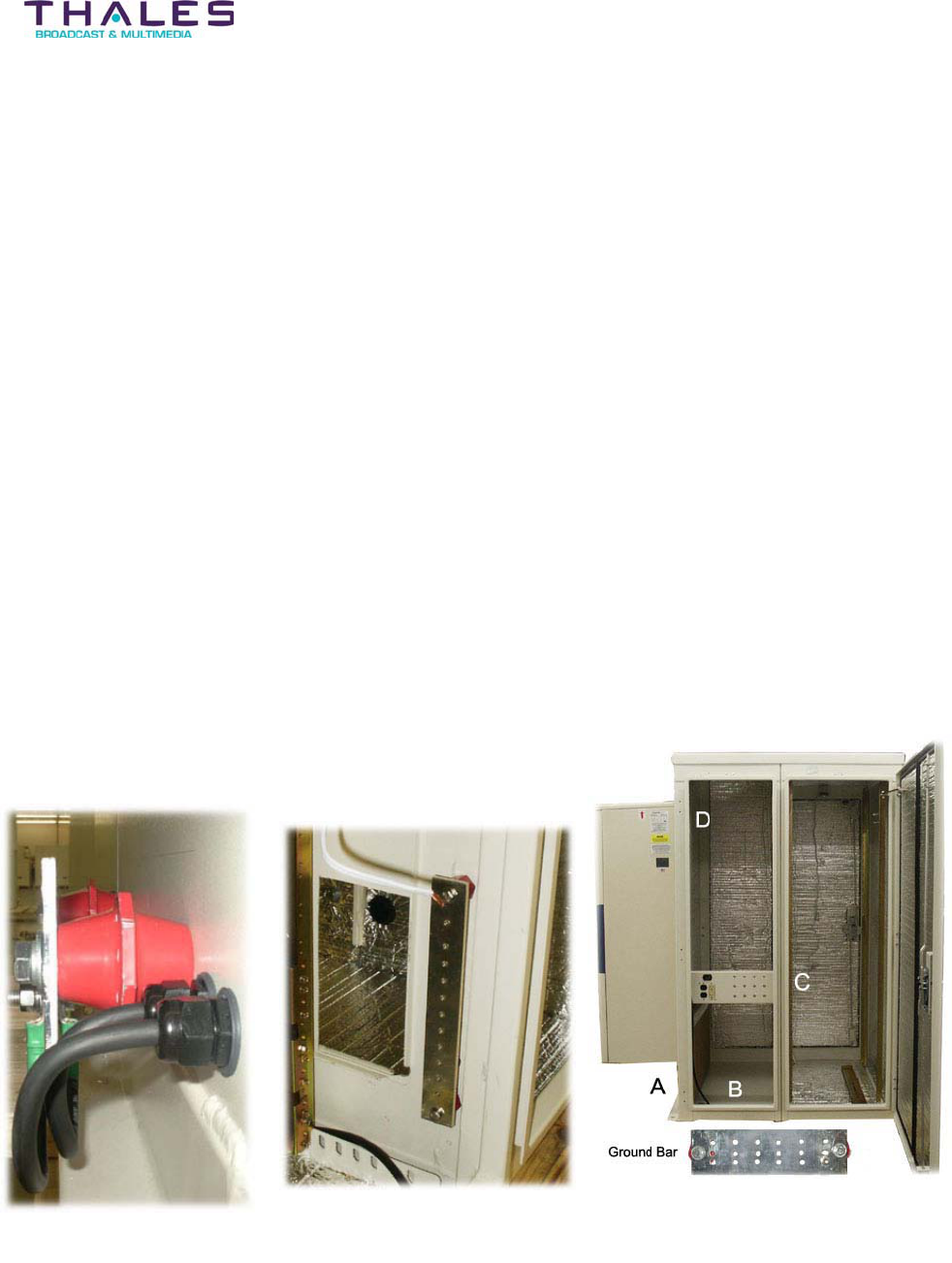
5.7 System Grounding
For proper system operation, it is imperative that the system be adequately grounded. Each
individual equipment-rack requires grounding to the main building ground. The basic grounding
scheme is provided below:
A: User Ground: Tie to building ground
B: Internal Ground Bar: Phone line Interface
Front View
C: Internal Equipment Ground Bar: Wired to all Chassis.
D: RF Surge Arrestor Ground Bar
Earth Grounding Scheme
System Description - 30 -
®
Affinity LBD-200C-N1 Transmitter
Product Manual
6 General System Description
The Thales Affinity® LBD-200C-N1 low power solid-state DVB-H transmitter is intended to
provide maximum flexibility for site layout and installation. The Affinity® transmitter contains
integrated modular assemblies that were designed to fit into EIA standard 19” rack units. The
transmitter consists of several of these rack units that house, with the exception of the
Downconverter Module, RF filter and HVAC unit, the major components that make up the
transmitter system. This module design allows operators of the transmitter to easily install,
operate and maintain the equipment.
The basic topology of the Affinity® LBD-200C-N1 transmitter configuration is as follows:
x
x
x
x
x
x
x
x
x
x
Site Management System
Satellite Receiver and
Remultiplexer
Sirius DVB-H Exciter
Front-End Power Supply
Driver Section
oPower Supply Module
oUpconverter Module
oDownconverter Module
Power Amplifier (PA)
Segments
UPS system
RF Filter
Phone System Interface
HVAC Unit
The low power microwave
transmission system transmits a
digitally modulated average power
signal on a single 1670-1675MHz
channel. The LBD-200C-N1
generates 200 watts average power using a COFDM modulation scheme.
Digital transmission techniques provide superior performance over analog methods with
reduced susceptibility to noise and co-channel interference. COFDM modulation provides
exceptional throughput and spectral efficiency, while meeting the needs of mobility. The system
architecture is based on: advanced transistor technology, low-loss power combining, and
distributed control and power conversion. Some unique advantages of this new design are:
flexibility/scalability, lower downtime, and lower operating costs. The modular structure of this

System Description - 31 -
®
Affinity LBD-200C-N1 Transmitter
Product Manual
system allows for quick and easy replacement of malfunctioning plug-in modules resulting in
less downtime and convenient scalability. The high efficiency design and small size decreases
operating expenses. Each of the plug-in modules is self-managing. When a fault occurs within a
module, the application software detects and automatically signals and/or records the fault. If a
catastrophic failure occurs within any of the plug-in modules, the Master Support Interface (MSI)
system will detect the failure and perform an automatic controlled shutdown.
One key benefit of this series of transmitters is the “Hot Swap” replacement capability. The hot
swap feature allows the transmitter to continue functioning while a faulty power amplifier
segment is replaced. During replacement the transmitter will continue operating with only slight
power loss and with little to no change in the noise floor. Full transmitter power will be restored
when the replacement amplifier is plugged into the amplifier chassis.
Should any of the other plug-in modules contained in the transmitter require replacement, a brief
transmission interruption will occur when the faulty plug-in is removed. Transmission is restored
when the replacement module is plugged in.

Installation - 32 -
®
Affinity LBD-200C-N1 Transmitter
Product Manual
7 Installation
(Reference L-Band XMTR Enclosure Planning document 38-0019-040 located in Section 25)
WARNING
This equipment utilizes a grounding plug on all power cords. For personal safety, do not
defeat this feature. As with all similar types of equipment, high voltage can be accessed when
the chassis cover is removed. Special care should be given in areas of fuses, line switches,
and power supplies. Modern high power solid-state equipment contains low output voltage
power supplies with very high current capability. To prevent severe burns, avoid contacting
these circuits with conductive jewelry such as rings, watches etc. When servicing the
transmission line and antenna, care must be taken to avoid exposure to high-energy
microwave.
7.1 Installation of Transmitter Sub-Chassis
The transmitter modules require twelve rack units of vertical rack space (not including the
exciter).
Install the LBD-200C-N1 support rails within the equipment rack as shown in the site-specific
cabinet layout diagram. Failure to use the support rails will result in damage to the transmitter
chassis. Install rack clips to secure the transmitter front panel. Slide the chassis onto the
support rails and secure to the rack clips. The rear door of the transmitter opens for
maintenance access. Nothing should be mounted to the rear of the rack that will interfere with
this access.
Ensure AC power outlets and other brackets are appropriately located so as not to block the
rear of the transmitter. To ensure that no electrical arcing occurs, perform the installation of the
individual module segments of the transmitter in the order discussed below:
Installation - 33 -
Affinity® LBD-200C-N1 Transmitter
Product Manual
7.1.1 Installation of Site Management System
Pending
Installation - 34 -
®
Affinity LBD-200C-N1 Transmitter
Product Manual
7.1.2 Installation of Satellite Receiver and Remultiplexer
Pending
Installation - 35 -
®
Affinity LBD-200C-N1 Transmitter
Product Manual
7.1.3 Installation of Sirius DVB-H Exciter
Pending
Installation - 36 -
Affinity® LBD-200C-N1 Transmitter
Product Manual
7.1.4 Installation of Driver Plug-In Modules
The Driver Plug-in Modules slide into the sub-chassis on nylon slides and connect to the Driver
Backplane board via floating connectors. The driver section of the transmitter occupies the left
quadrant of rack space directly below the Sirius Exciter and adjacent to the Power Amplifier
Segments. Within the driver section, the Power Supply Module occupies the left slot, while the
Upconverter Module occupies the right slot. To install the driver plug-ins, slide the module into
its proper location until fully seated. There is a disconnect switch on the backplane board to
ensure that there is no arcing between connections before the segment is fully engaged. Once
the plug-in is in place, tighten the front panel thumbscrews to ensure that the plug-in remains
securely in place.
Driver Assembly
Power Supply Module Upconverter Module
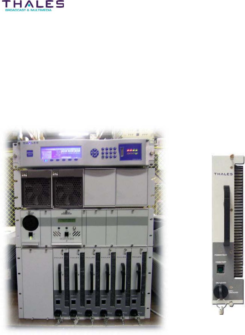
Installation - 37 -
®
Affinity LBD-200C-N1 Transmitter
Product Manual
7.1.5 Installation of Power Amplifier Segments
The Power Amplifier Segments (PAS) slide into the sub-chassis amplifier bay on nylon slides
and connect to the PA Backplane via floating connectors. The key-lock switch, located on the
amplifier front panel, must be in the OFF/UNLOCKED position to plug the segment in. This
removes the potential for arcing between connections before the segment is fully engaged.
Once the segment is slid into place, thumbscrews on the front panel secure the segment to the
sub-chassis. The key-lock switch may be turned to the ON/LOCKED position to apply power to
the amplifier segment. Once the key-lock switch is turned on, the segment will automatically set
the gain and currents of the amplifier.
Amplifier positions within the Affinity® LBD-200C-N1 transmitter sub-chassis
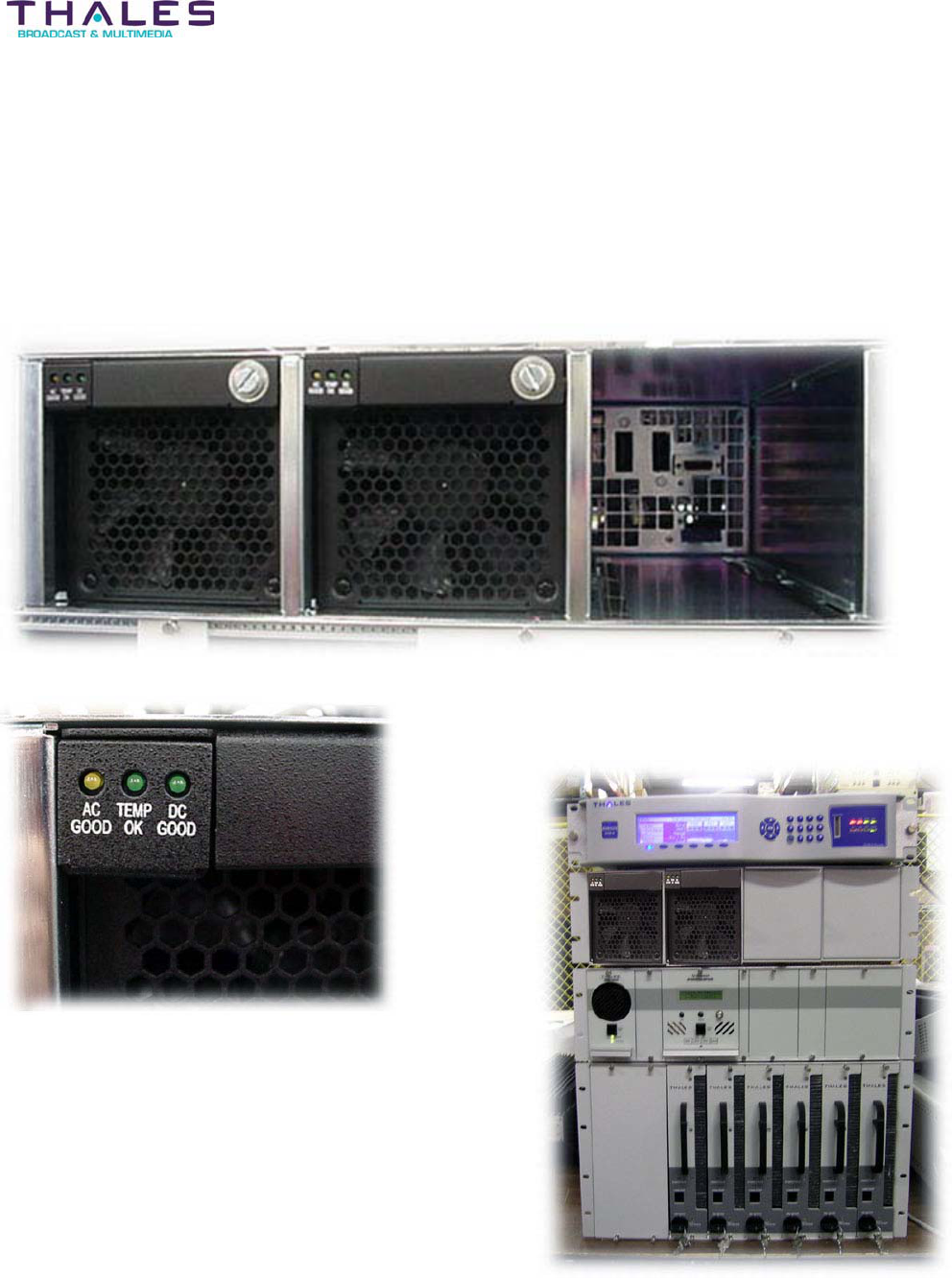
Installation - 38 -
®
Affinity LBD-200C-N1 Transmitter
Product Manual
7.1.6 Installation of Front-End Power Supplies
The two 48V Front-End Power Supplies occupy 3RU of chassis rack space and are installed left
justified in the bay located above the Driver and Power Amplifier Segments. Each Front-End
Power Supply slides into the sub-chassis on nylon slides and connects to the Front-End Power
Supply Backplane via floating connectors.
Front-End Power Supply
Front-End Power Supply LED Indicators
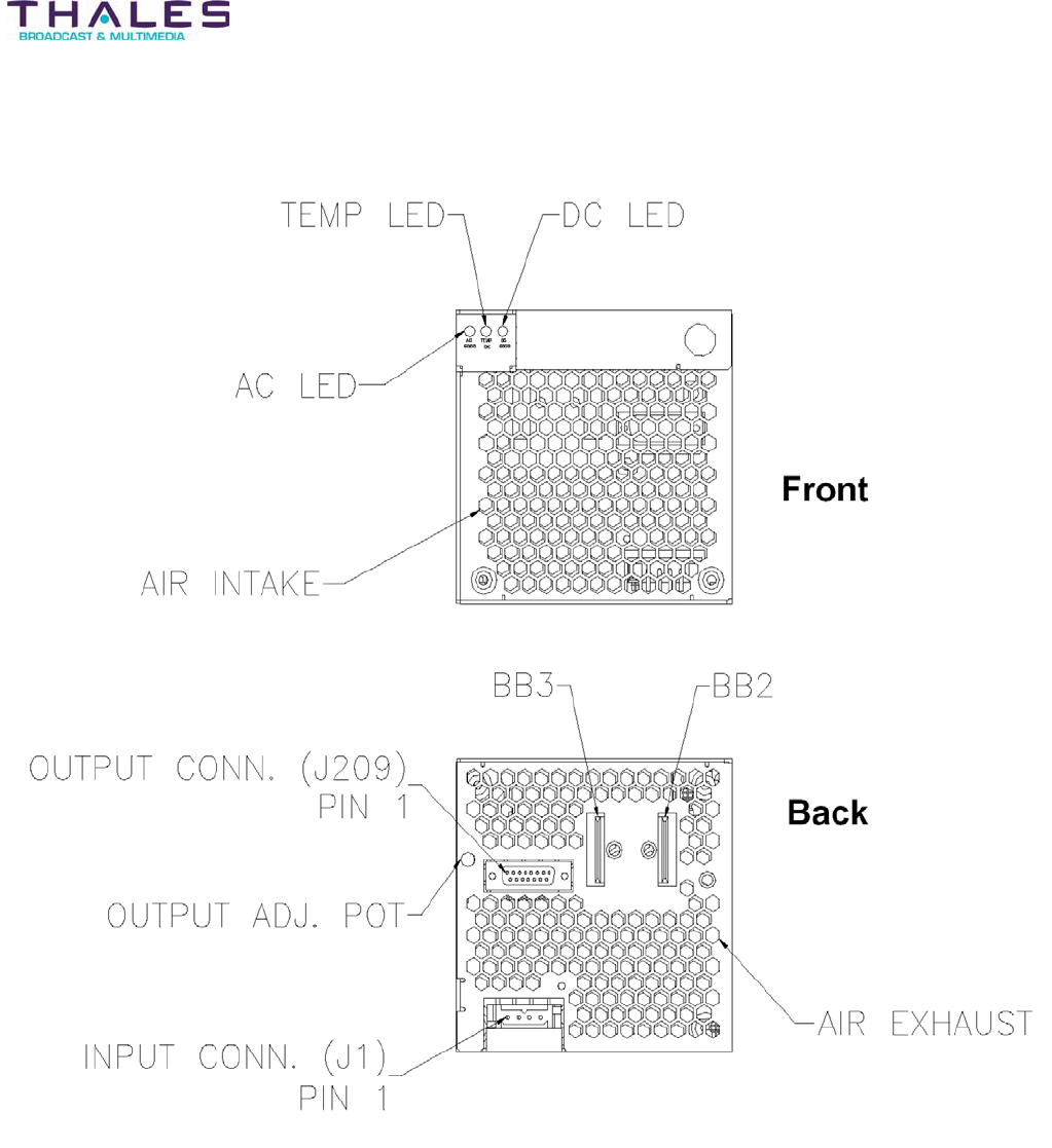
Installation - 39 -
®
Affinity LBD-200C-N1 Transmitter
Product Manual
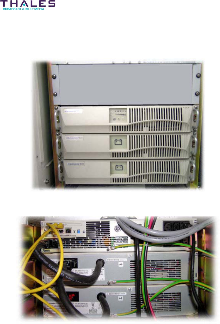
Installation - 40 -
®
Affinity LBD-200C-N1 Transmitter
Product Manual
7.1.7 Installation of UPS System
Pending
UPS System Front view
UPS System Rear view
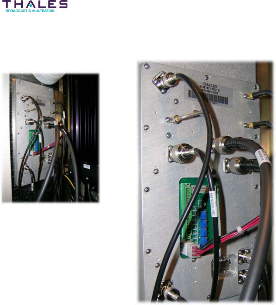
Installation - 41 -
®
Affinity LBD-200C-N1 Transmitter
Product Manual
7.1.8 Installation of Downconverter
Pending
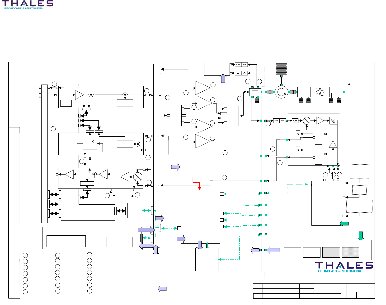
Block Diagram System Overview - 42 -
Affinity® LBD-200C-N1 Transmitter
Product Manual
Block Diagram System Overview
Need LBD200 version of block diagram
DRAWN:
RELEASED:
CHECKED:
TITLE:
REV: S1
REV
Description
Scale:
none
Sheet
1of 1
ECO#
NAME/DATE
THIS DOCUMENT AND THE INFORMATION IN IT IS THE PROPERTY OF THALES BROADCAST & MULTIMEDIA (THALES) THIS DOCUMENT
AND INFORMATION SHALL NOT BE REPRODUCED OR DICLOSED TO ANY PERSON OR ENTITY WITHOUT PRIOR WRITTEN CONSENT FROM
THALES. CE COCUMENT ET LES INFORMTIONS QU’IL CONTIENT SONT LA PROPIETE DE THALES BROADCAST & MULTIMEDIA ILS NE
PEUVENT ETRE REPRODUITS NI COMMUNIQUES A DES TIERS SANS L’AUTHORISATION PREALABLE ECRITE DE THALES
HANDWRITTEN CHANGE FORBIDDEN
© THALES BROADCAST & MULTIMEDIA
2004
DWG. NUMBER:
47267347
B
SIZE:
034
DTC
Single Drive Block Diagram,
LBD125C-N1 System Overview
A. Castro 09-07-2004
RF OUTPUT
N Female
COFDM = 100 Watts
(After Output Filter)
DRIVER
ASI MPEG
TRANSPORT
STREAM
BNC Female
DVB-H
Exciter
IF = 672.5 MHz
5MHz BW
-18dBm avg pwr ±3dB
FREQ. REF. IN
BNC Female
Nominal +10dBm ±3dB
FRONT PANEL
POWER AMPLIFIER
CAGE ∆≅37dB
CPLR –36dB
RF Detector
47267377
Management
Support
Interface
47266769.01
POWER SUPPLY PLUG-IN 47266099.04
Multi-Output Power Supply
With embedded MCU
UPCONVERTER PLUG-IN 47267228.01
Distribution
and MCU
J-3
RF Sample
Black Plug
1PPS
BNC Female
Distribution
and MCU
SNMP
Device
Server
(Optional)
LAN INTERFACE
RJ45 Ethernet
REMOTE RS485
INTERFACE
ABCS
INTERFACE
RS232
RS485
Modulator Comms
Local RS 4 8 5
PAS Fault/Presence
PAS Monitoring
1670-1675MHz
48VDC
AC MAIN
230VAC Nominal
48VDC
FRONT END POWER SUPPLY 47267076.02
48V 1200W
48V 1200W
48V 1200W
48V 1200W
LOCAL RS485
INTERFACE
RF Feedback (linear)
RF Feedback (non-linear)
Black Plug
Combiner
47267155
Splitter
754545-01
Load
Circulator Mask filter
-30dB -30dB
47267238
Converter
BPF
L-Band
47267288
In-Signal
?+
ALC
LO
Presence
47267375
ALC
47267240
L-Band IPA
Up-Converter
Output Power
Driver Section Back Panel
Temp
Front Panel & LCD Display
Interface
Display
RS232
Keyboard
J-5
J-4 J-3
J-2
J-1
J-4
J-7
J-6
J-1J-2
J-2
J-3
J-1
1
1 47266461.00-110
2 47266197.00-190
3 47266195.00-150
4 47266194.00-050
5 47266194.00-052
6 47266195.00-090
7 47266196.00-200
8 47266197.00-050
2
3
4
5
6
6
7
8
÷2
÷3
47267339
Down-Converter
Rear Door
Power Supply Back Panel
RJ11 (x2)
RJ11 (x1)
D-Sub 15
RJ45 Ethernet
48VDC
48VDC
48VDC
∆= 38dB
∆= 38dB
∆= 38dB
∆= 38dB
PA PLUG-INS
47267227.01
Amplifier Segments
Back Plane
-6dB -3dB
-17dB -14dB
-3dB
9 47266891.00-250
10 47267342.00-250
10
9
11
11 47266184.00-163
12 47266184.00-101
11
11
12
12
12
12
11
11
13 60-070-071
13
14
14
14 47266185.00-360
15 400279-33-60
16 400279-09-60
17 400279-09-36
18 400279-12-60
15
18
16
17
17
17
1GHzUHF FdB
19 47266184.00-101
20 60-070-071
21 47266185.00-360
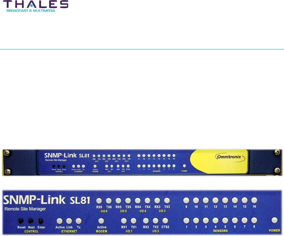
Site Management System - 43 -
®
Affinity LBD-200C-N1 Transmitter
Product Manual
8 Site Management System Description
8.1 Status Monitoring and Control System
The Omnitronix SL81 Status Monitoring and Control System (SMCS) is provided for use with
Affinity® transmitters. The SMCS is a rack-mounted unit located within the transmitter cabinet. It
provides a web interface and an SNMP agent for remote control. Remote access to the SNMP
agent is available through a GSM connection or via dial-up modem and a PSTN line. All events
and faults are stored in a logbook with date and timestamps.
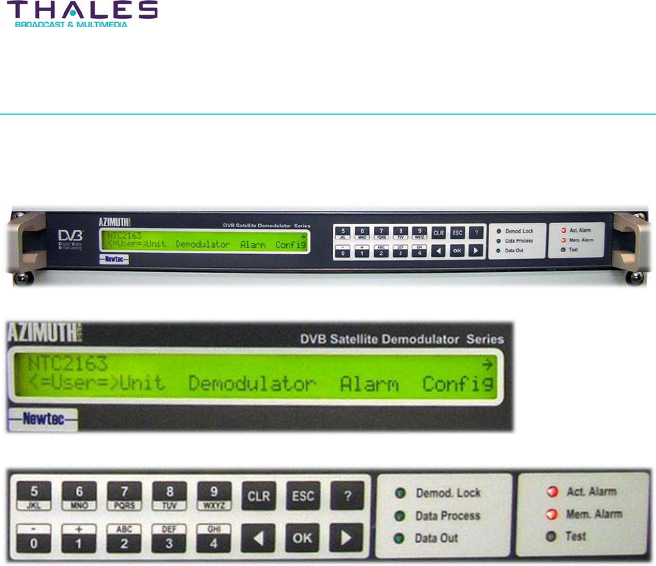
Satellite Receiver and Remultiplexer - 44 -
®
Affinity LBD-200C-N1 Transmitter
Product Manual
9 Satellite Receiver and Remultiplexer Description
Pending
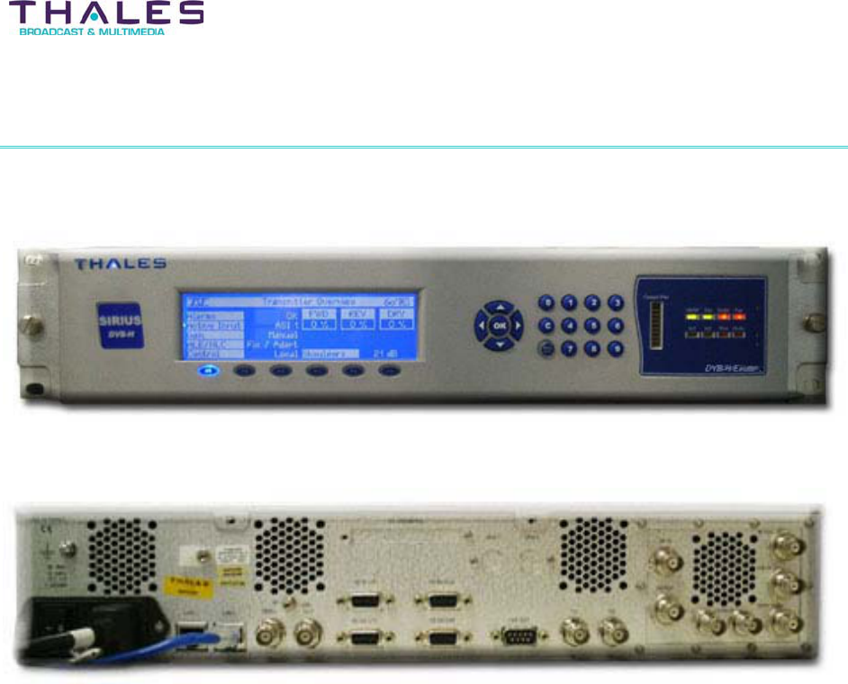
Exciter Configuration Description - 45 -
®
Affinity LBD-200C-N1 Transmitter
Product Manual
10 Sirius DVB-H Exciter Description
Exciter front-view
Exciter rear-view
10.1 Introduction
The Thales Sirius DVB-H Digital RF Exciter, which is integrated in the Affinity® LBD-200C-N1
transmitter, is part of the family of state-of-the-art Digital Modulator/RF Exciters based on a
unique hardware platform capable of delivering the proper pre-corrected RF low power DVB-H,
ATSC, DRM or other processing waveform signal to an amplifying chain. The Exciter is
contained in an independent 19” 2RU unit and includes all necessary power supplies and
interfaces. This very powerful platform is based on open standard technologies, and the latest
generation of FPGA processing.
For single drive configuration, the front panel of the RF exciter includes a LCMP (Local Control
& Monitoring Panel) made of a 2 RU front panel including a display and dedicated control
knobs.
Extended or remote operation can be achieved by using an embedded Web server from a
standard browser, or through the Omnitronix SNMP manager.
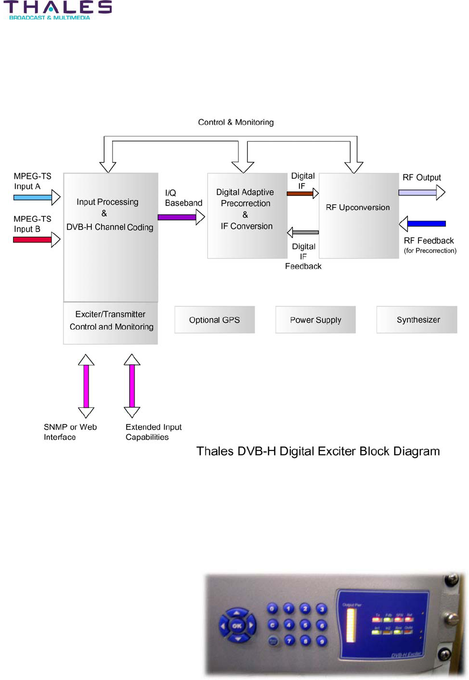
Exciter Configuration Description - 46 -
®
Affinity LBD-200C-N1 Transmitter
Product Manual
The block diagram below provides a functional view of the Sirius DVB-H Digital RF Exciter.
Single Drive Operation
In the Single Drive (SD) configuration, the Thales Sirius DVB-H Digital RF Exciter is equipped
with a dedicated LCMP (Local Control & Monitoring Panel) located on the front of the unit. This
dedicated LCMP includes a display and control buttons.
The selection of the various menus is made by means of button-switches located on the front
panel of the Exciter.
Sirius Exciter LCMP
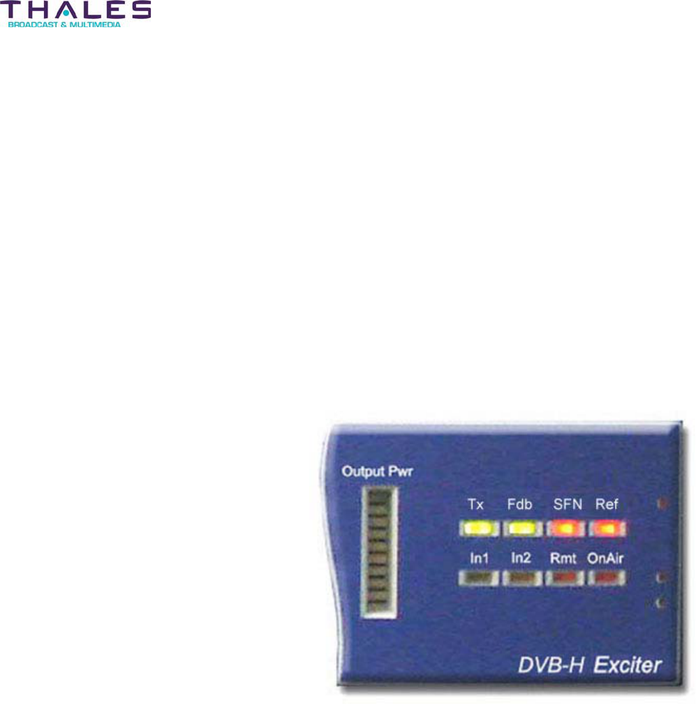
Exciter Configuration Description - 47 -
®
Affinity LBD-200C-N1 Transmitter
Product Manual
The menus are as follows:
x Overview: provides complete access to the main parameters (status of the input,
modulation, clock reference, QoS summary and operating frequency)
x Input settings: provides an overall view of the parameters selected for the two
inputs
x Threshold settings: displays the parameters selected for MER, ripple and shoulder
x Modulation settings: displays the selected reference clock, bandwidth, mode, type
of modulation and associated protection ratio for each input
x Transmitter settings: displays frequency, output power, signal attenuation,
selected linear equalization, non linear pre-correction, clipping, operating mode
x The last menu provides a direct manual access to fast switch to the mute position
The Local Control and Monitoring Panel (LCMP) of the Exciter provides a readout for output
power and the following alarm indicators:
x TX fault / Hardware fault synthesis
x RF feedback
x SFN mode
x Reference status
x ASI input 1
x ASI input 2
x Remote or local control mode
x On-Air indication
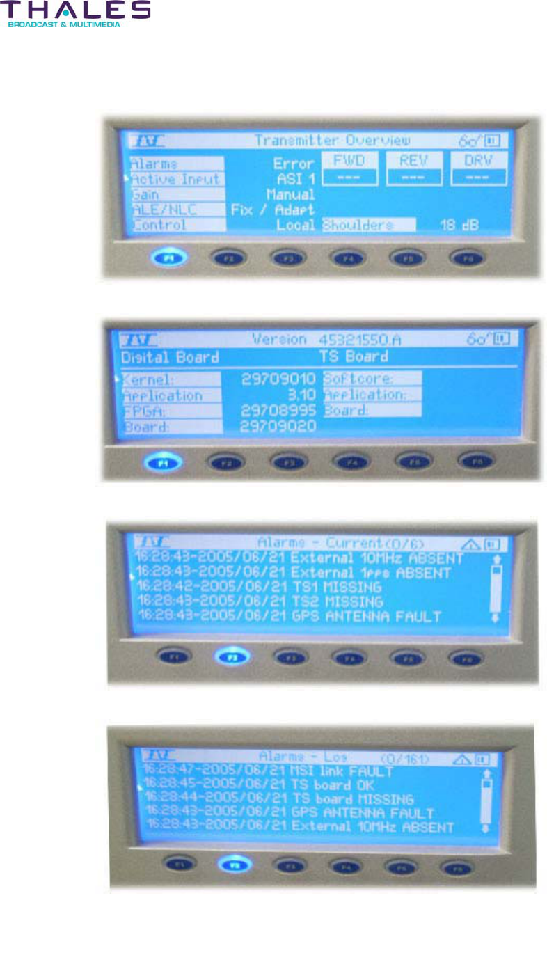
Exciter Configuration Description - 48 -
®
Affinity LBD-200C-N1 Transmitter
Product Manual
Sample Exciter Display Screens
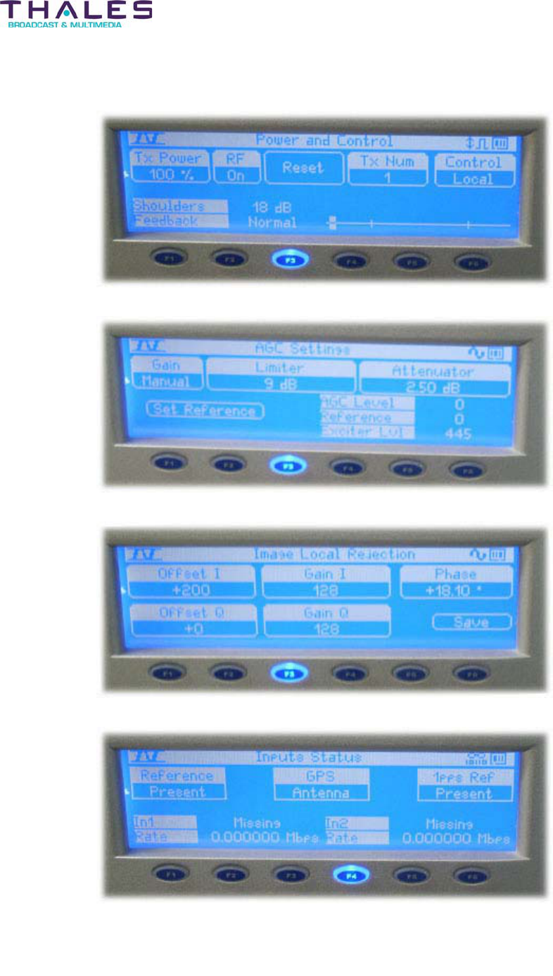
Exciter Configuration Description - 49 -
®
Affinity LBD-200C-N1 Transmitter
Product Manual
Sample Exciter Display Screens
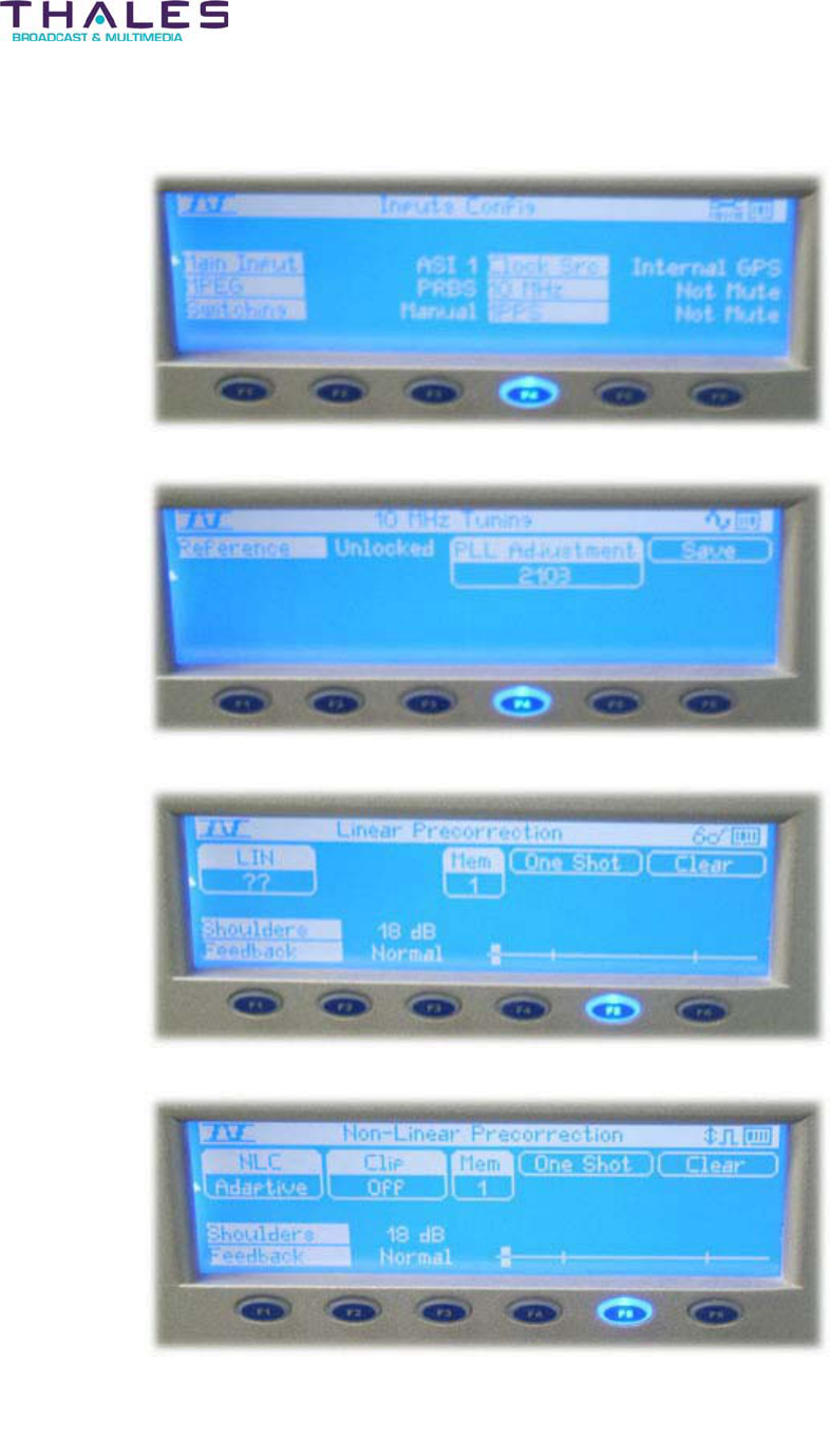
Exciter Configuration Description - 50 -
®
Affinity LBD-200C-N1 Transmitter
Product Manual
Sample Exciter Display Screens
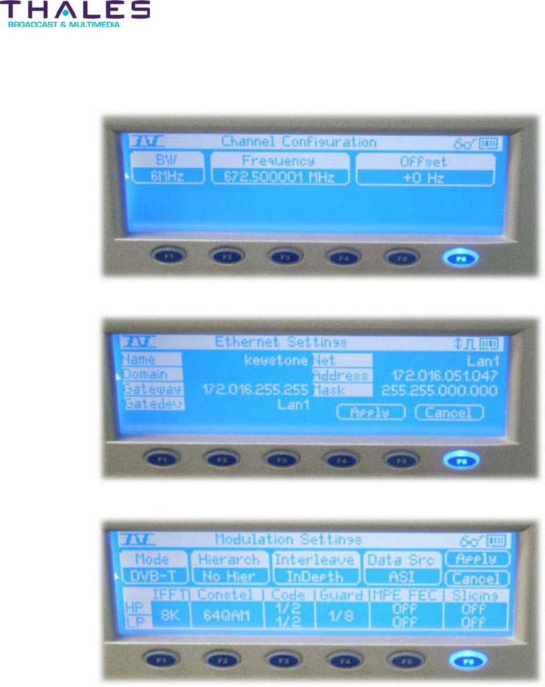
Exciter Configuration Description - 51 -
®
Affinity LBD-200C-N1 Transmitter
Product Manual
Sample Exciter Display Screens

Exciter Configuration Description - 52 -
®
Affinity LBD-200C-N1 Transmitter
Product Manual
10.1.1 Remote Operation
(Optional)
For SD configuration the remote operation is enabled by either the SNMP agent or the Web
server, both of which are embedded in the Sirius DVB-H RF Exciter.
10.1.2 SNMP Agent and Web Server
The objective of the SNMP agent is to ensure remote operation of the equipment by using the
SNMP protocol by means of the IP protocol supported by an Ethernet interface.
The SNMP agent is responsible for:
x Communication with the equipment by means of SNMP protocol
x Communication with the equipment by sending e-mail
x Implementation of FTP and TELNET protocols
The control of the equipment in this manner is only enabled when remote operation is selected.
The SNMP agent in both local and remote modes of operation always accepts monitoring
requests.
Access to the SNMP agent for either writing and/or reading is organized by means of user
profiles defining individual rights and conditions for access. The SNMP agent integrates SMTP
protocol allowing events to be sent via e-mail. Important events will automatically generate
“traps”. The links between events and traps are configurable by the operator.
A web server allows the equipment to be controlled from any standard browser by means of the
HTTP protocol. The control of the equipment in this manner is only enabled when remote
operation is selected. The web server, in both local and remote modes, always accepts
monitoring requests.
The web server provides:
x Static information such as leaflet and user manual of the equipment
x Dynamic information including displays of all status alarms and faults, and operating
parameters
x Operating or configuration control protected by means of user profiles and
passwords
x Access to equipment logbook
The following screen shots represent the main page and the page dedicated to the Sirius DVB-
H RF Exciter. These should provide an accurate representation of the capability of the
embedded web server.
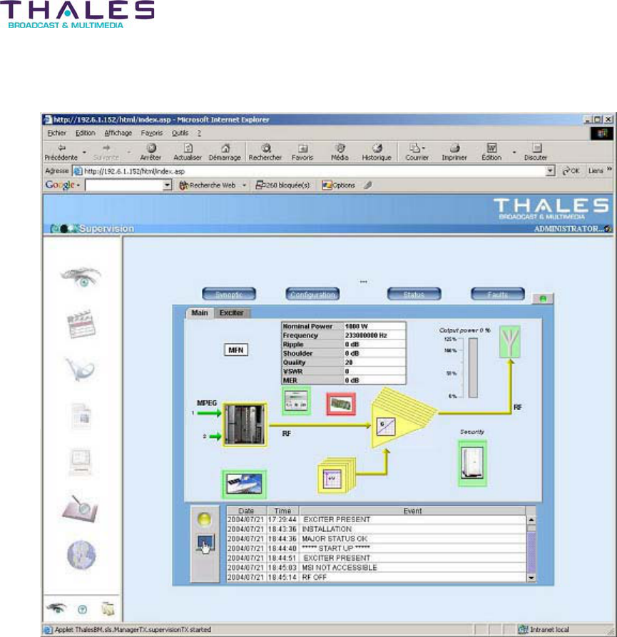
Exciter Configuration Description - 53 -
®
Affinity LBD-200C-N1 Transmitter
Product Manual
Main page
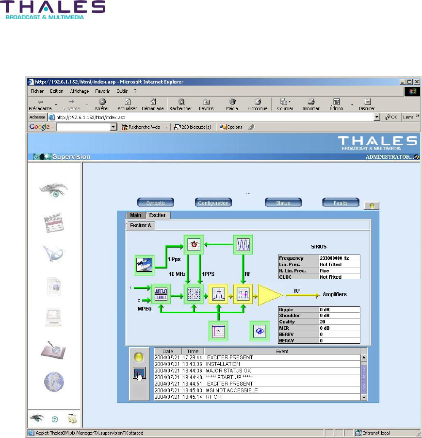
Exciter Configuration Description - 54 -
®
Affinity LBD-200C-N1 Transmitter
Product Manual
Sirius DVB-H Exciter page