Thomson Broadcast and Multimedia LBD-25200 Affinity L-Band Transmitter for Mobile Media Svs. User Manual Affinity LBD 200C N1 DRAFT1
Thomson Broadcast & Multimedia, Inc. Affinity L-Band Transmitter for Mobile Media Svs. Affinity LBD 200C N1 DRAFT1
Contents
- 1. Software Users Guide
- 2. 200W User Manual part 1
- 3. 200W User Manual part 2
- 4. 200W User Manual part 3
200W User Manual part 3
Power Amplifier Module - 115 -
®
Affinity LBD-200C-N1 Transmitter
Product Manual
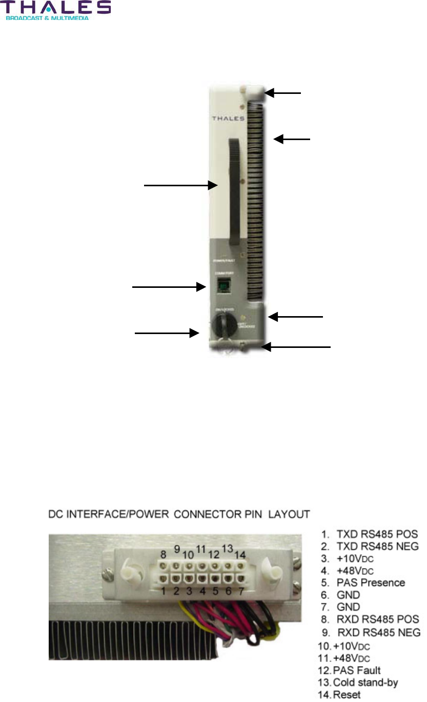
Thumbscrew
Heatsink
Handle
Key lock Assembly
LED
Thumbscrew
Communication Port
PA Module Rear Panel Assembly
The Rear Panel Assembly of the PA Module consists of a UHF OUTPUT a UHF INPUT and a
DC INTERFACE/POWER CONNECTOR.
The UHF OUTPUT is the point at which the UHF signal is connected to the RF System
The UHF INPUT is the point at which the UHF signal is received from the Driver Section.
The DC INTERFACE/POWER CONNECTOR is the point at which the power supply voltages,
control lines and RS-485 communication signals for the PA Module are located.
Power Amplifier Module - 116 -
Affinity® LBD-200C-N1 Transmitter
Product Manual
Front-End Power Supply Module - 117 -
®
Affinity LBD-200C-N1 Transmitter
Product Manual
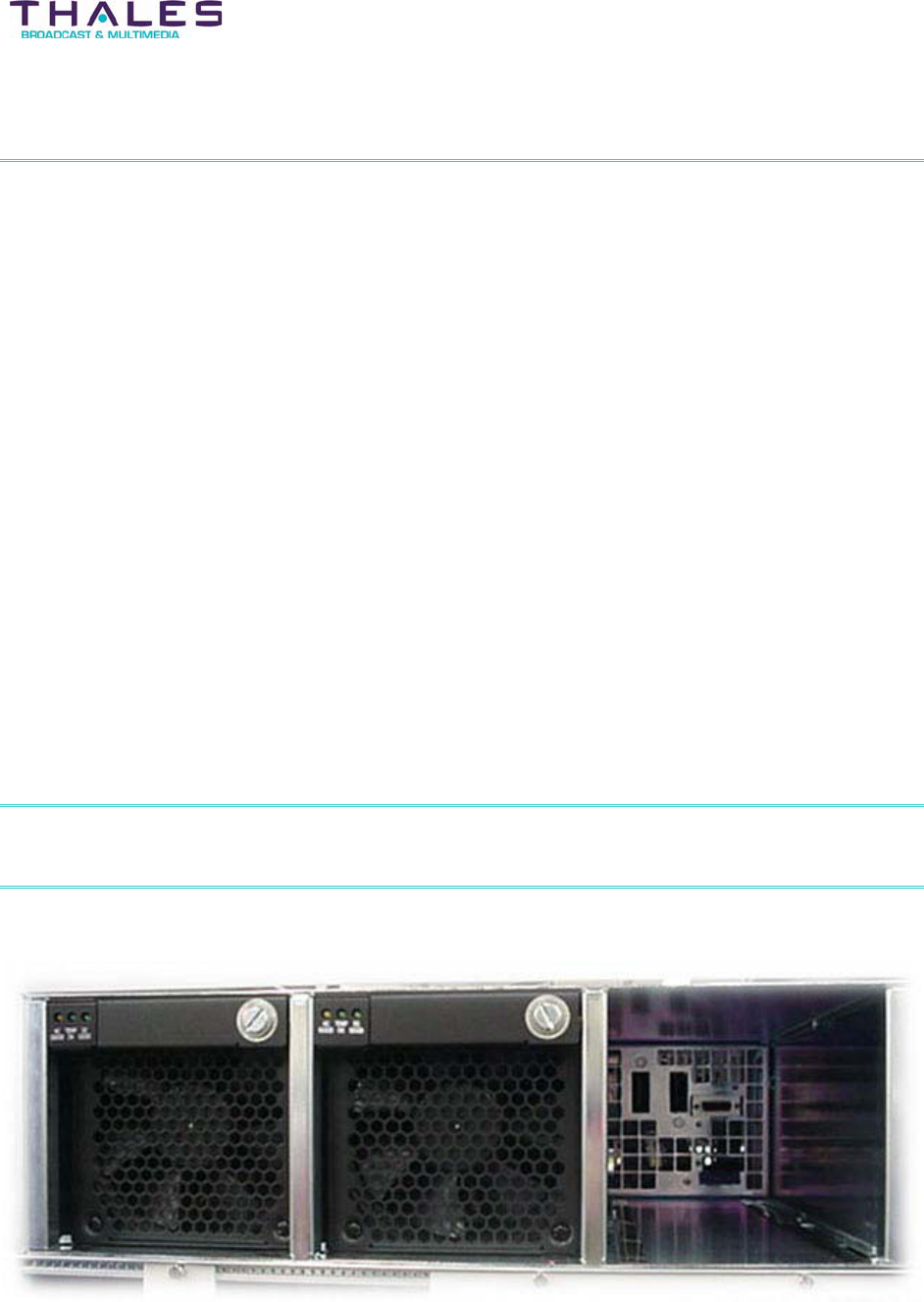
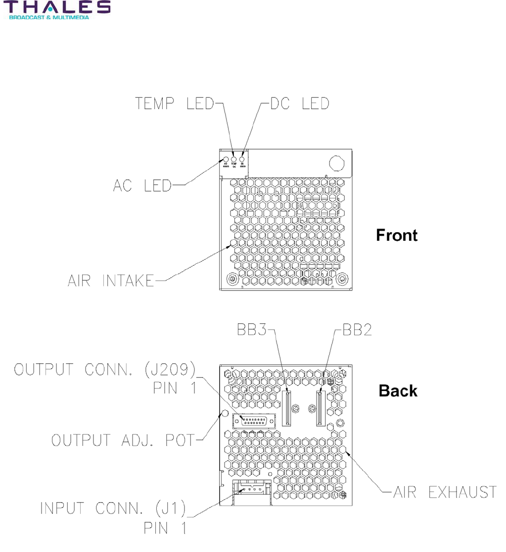
15 Front-End Power Supply Description
The Front-End Power Supply Module provides the 48VDC level required to power the Driver
and PA Modules of the Affinity LBD-200C-N1 transmitter .The Front-End Power Supply Module
outputs the 48VDC to the connector boards located within the Sub-Chassis Assembly. The
Driver and Amplifiers derive the power from these connector board assemblies.
The Front-End Power Supply Module is a 4000-Watt device containing current limiting, thermal
shut down, and fuse protection circuitry. The required input voltage is 208VAC 3-phase @
50Hz.-60Hz. The nominal output voltage is +48VDC. A potentiometer on the Front-End Power
Supply Module is used to adjust the output supply level (factory adjust).
LED indicators located on the supply front panel assembly provide visual feedback of Front-End
Power Supply operation.
Two internal 600 CFM forced air fans provide convection cooling for the Front-End Power
Supply Module.
The Front-End Power Supply is plugged into the Power Supply Adapter located in the Chassis
assembly.
The 5.25” high, Front-End Power Supply Chassis can contain up to three 48VDC power
supplies. The rack is designed to allow the power supply modules to operate in a current
sharing mode when more than one module is installed (N+1 applications). The Power Supply
Chassis operates off the mains AC power and is fuse protected on TB1.
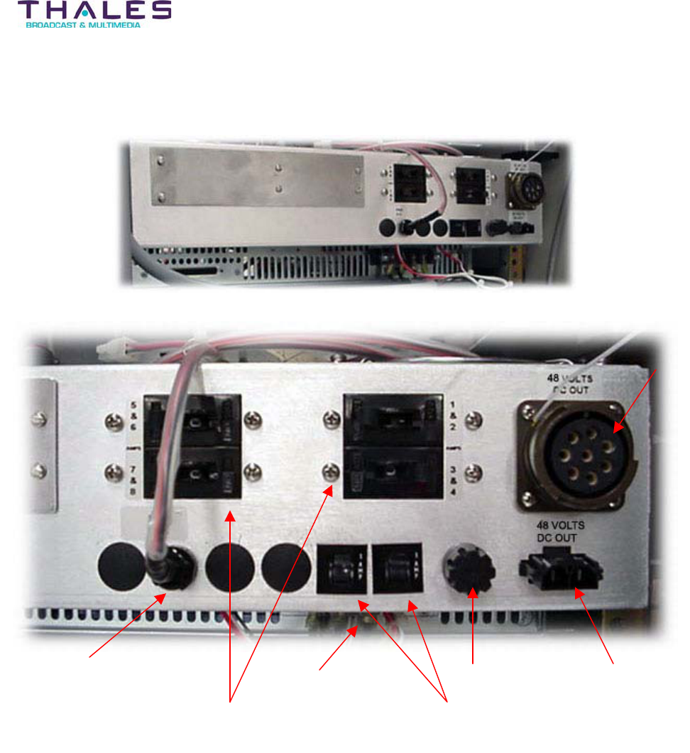
A circuit breaker assembly is attached to the rear of the chassis to provide DC over-current
protection for the PA Modules.
The Front-End Power Supply Modules are “Hot Swap” compatible. When operated in N+1
configurations, defective supplies may be removed and replaced without shutting the entire
transmitter system down.
Front-End Power Supply - 118 -
Affinity® LBD-200C-N1 Transmitter
Product Manual
48VDC
out to
Amplifier
Chassis
PA Power Switch Circuit
Breakers 1&2, 3&4, 5&6, 7&8
48VDC out to
Driver Chassis
4-
A
m
p
Fuse
PA Fan Circuit Breakers
for Amplifiers 1-4 & 5-8
A
C In
p
ut
Fan Output (AC) to
Amplifier Chassis
Front-End Power Supply - 119 -
Affinity® LBD-200C-N1 Transmitter
Product Manual
CAR4010T & 4030T
4000 Watt Single Output Rectifier Modules
97MS2101
Rev. B - 03.15.04
Cherokee International
■
Headquarters
2841 Dow Avenue, Tustin CA. 92780 - USA
714.544.6665 (t)
■
714.838.4742 (f)
www.cherokeepwr.com
Cherokee International
■
European Operations
Boulevard de l'Europe, 131
■
B-1301 Wavre - Belgium
+32.10.438.510 (t)
■
+32.10.438.213 (f)
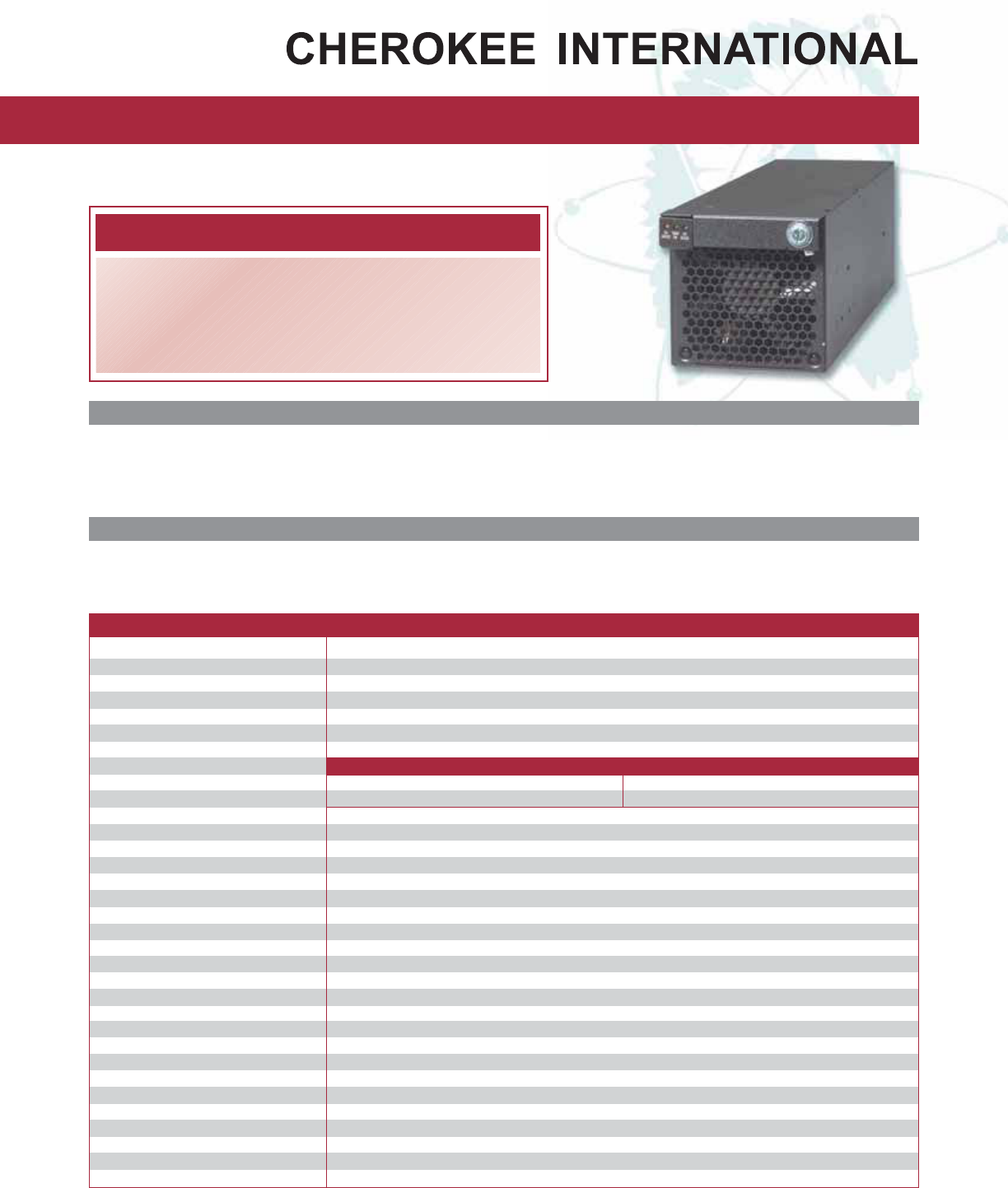
CAR4010T & 4030T
■Hot-Swap N+1 Redundancy
■Single phase or Three phase Input
■Power Factor Correction
■Over Voltage, Over Current and Thermal Protection.
■Visual LED Indicators
■19” 3U high rack available
Specifications CAR 4010T & 4030T
Input Voltage Range CAR4010T: 180-264VAC, 47-63Hz 1Ø / CAR4030T: 180-264VAC, 47-63Hz 3Ø
Input Current (maximum) 25.5A @ Full Load and 180VAC, 1Ø and 15A per phase @ Full Load and 180VAC, 3Ø
Inrush Current 50A max
Input Fuse 30A 3AG, Internal Axial Type for 1Ø and 20A 3AG, Internal Axial Type for 3Ø
Input Transient Protection MOV and Gas tube
Power Factor 0.99 (for CAR4010T) and 0.95 (for CAR4030T) at full load and nominal line
Efficiency 89% typical at 230VAC
Output Configuration V1 V2 Standby Output
CAR4010L1TN/CAR4030L1TN -54V @ 74A 5V @0.5A
CAR4010K1T/CAR4030K1T 27V @ 148A 5V @ 0.5A
Output Voltage Range - 40 to -58V (for CAR4010L1T) and 20 to 29V (for CAR4010K1T) with external programming
Line Regulation 0.5% using remote sense (5% on Stand-by Voltage)
Load Regulation 0.5% using remote sense (5% on Stand-by Voltage)
Output Ripple & Noise <1% (pk-pk)
Transient Response 3% max deviation 0.50ms recovery time for a 25% load change
Start-up Time 2 seconds
Hold-up Time >20ms at low line
Overshoot / Undershoot 1% at turn ON / OFF
Temperature Coefficient 0.02% per °C
Remote ON / OFF Logic 1 (TTL High) or open enables unit (ON), Logic 0 (TTL Low) or short shuts unit down (OFF)
Power Fail Signal Signal goes low (TTL low) 2ms before loss of output regulation
Current Limit Protection 110-140% V1, 5VSB <2.5A. Automatic recovery.
Over Voltage Protection - 58.5 to -59.5V (for CAR4010L1TN) and 29.5 to 30.5V (for CAR4010K1T). Reset by cycling input power.
Over Temperature Protection Automatic shutdown with auto recovery. Thermal shutdown point @ 95°C
MTBF 300,000 hrs per Bellcore standard
Output Power Good TTL High = Power Good, TTL Low = Output out of limits
LED Indicators DC Good: Green LED; Temperature OK: Green LED; and AC Good: Amber LED
Operating Temperature 0°C to 50°C at rated output power. Supply derates linearly from 50°C to 65°C at 2.2% per °C
Cooling Self contained ball bearing fan.
Shock & Vibration NEBS Compliant to IEC68-2-27 & MIL-STD-810E, Telcordia GR-63-CORE; GR-487-CORE
EMI/EMC Meets EN61000-3-2, -3 CISPR22 and FCC Part 15 Class A, Bellcore GR-1089-Core
Safety Approvals UL1950, CSA 22.2 No. 650, TUV EN60950 & CE Mark
Weight 13.5 pounds
Features Benefits
■No minimum load requirements ■Eliminates the need for preload on system backplane
■Modular design ■Easy insertion and extraction during hot swap
■Single phase or three phase inputs ■One stop shopping, breadth of line for 24V and 48V outputs
■Constant power characteristic ■Better suited for battery charging applications
Key Market Segments & Applications
Telecommunications
■Wireless/Cellular ■PCS Installations
■Central Office Switching ■Bulk power front ends for distributed power architecture
Cherokee reserves the right to make changes to the product described without notice. No liability is assumed as a result of its use nor for any infringement on the rights of others.
CAR4010T & 4030T
4000 Watt Single Output Rectifier Modules
97MS2101
Rev. B - 03.15.04
Cherokee International
■
Headquarters
2841 Dow Avenue, Tustin CA. 92780 - USA
714.544.6665 (t)
■
714.838.4742 (f)
www.cherokeepwr.com
Cherokee International
■
European Operations
Boulevard de l'Europe, 131
■
B-1301 Wavre - Belgium
+32.10.438.510 (t)
■
+32.10.438.213 (f)
Outline Drawing
Output (Bus Bar)
CAR4010L1TN BB1=V1 BB2=RTN
CAR4010 K1T BB1=RTN BB2=V1
Input Connector CAR4010T CAR4030T
Connector Number Pin Number Function Connector Number Pin Number Function
J1 1,4 Chasis Ground J1 1 Line 1
J1 2,5 Line (L) J1 2 Line 2
J1 3,6 Neutral (N) J1 3 Line 3
J1 4 Chasis Ground
Output Connector CAR4010T & CAR4030T
Connector Number Pin Number Function Connector Number Pin Number Function
J209 1 5V Stand By J209 9 AC Fail
J209 2 5V Stand By RTN J209 10 V Progammable
J209 3 Module Present J209 11 V1 Sense
J209 4 Power Good J209 12 I Monitor
J209 5 ON / OFF J209 13 Temperature OK
J209 6 I Share J209 14 RS (Return Sense)
J209 7 Mod-Enable J209 15 N/C
J209 8 OVP Test Point
Model Selection Guide
CAR 40X0 X1T X – 1A
Options N - Negative Vout
X - Positive Vout
L - 48 Vout
K - 24 Vout
4010 - 4000W, Single Phase
4030 - 4000W, Three Phase
Output Voltage
Output Power & Phase
Model (CAR Series)
Connector Information
Output: Elcon 538-17-00100
Option Connector: AMP 205205-2
Option Pins: AMP 205090-1
Input Connector:
CAR4010T - Positronics PLB06F0000
CAR4030T - Positronics PLA04F8000
Mating Connectors
Front View
Rear View (1 Phase) Rear View (3 Phase)
Top View Side View

Backplane/Interface Boards - 122 -
®
Affinity LBD-200C-N1 Transmitter
Product Manual
16 Backplane/Interface Board Description
16.1 Front-End Power Supply Backplane
The Front-End Power Supply Backplane is the electrical and physical receptacle for the
Front-End Power Supply assemblies. The backplane board is mounted to the Affinity® Chassis
and provides AC voltage to the Front-End Power Supplies. The DC output voltages from the
Front-End Power Supplies are applied to the backplane to be used as a source of power for the
Driver section and PA plug-in modules. The Front-End Power Supply Backplane also contains a
diagnostic interface that can be used, via the Omnitronix SL81 Status Monitoring and Control
System (SMCS), to monitor Front-End Power Supply status.
Front-End Power Supply Backplane board
AC power from the rear panel enters the Front-End
Power Supply Backplane board through connectors J3,
J4, and J5. The AC source enters the Front-End Power
Supplies through backplane connector J11. DC output
power from the Front-End Power Supplies is present on
J12 of the backplane board where it is distributed to the
other modules via backplane connector studs J6 and
J7. The 24-position dual row connectors, J1 and J2, are
used to communicate and monitor the other modules in
the sub-chassis. Three-position single row connector J9
and nine-position single row connector J10 connect to
the amplifier motherboard to establish communications
between the Driver Backplane board and PA segments.
16.2 Driver Backplane
The Driver Section (Power Supply and Upconverter modules) is electrically, and physically
connected to the Driver Backplane when plugged into the Chassis assembly. The connectivity
is established when the push-button switch located on the backplane is depressed. This occurs
when the Driver Section Power Supply is plugged into the Chassis. Removing the Driver
Section Power Supply Module will also remove power from the Driver Backplane. This is done
to prevent arching during a Hot Swap operation.
The Driver Backplane provides +8VDC, +12 VDC, -12 VDC, +24VDC and ground for the Driver
Section. The Driver Backplane also contains multidrop communication connectivity used by the
Driver Section assemblies.
Backplane/Interface Boards - 123 -
®
Affinity LBD-200C-N1 Transmitter
Product Manual
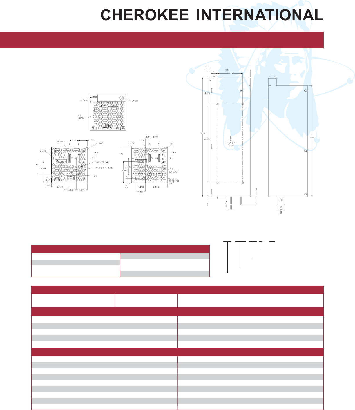
Driver Backplane
The Driver Section Power Supply module supplies the Driver
Backplane and Upconverter module with 5VDC, 12 VDC, –12 VDC,
and data through 48-pin DIN connections (1). The main power to
the Driver Section Power Supply plug-in is delivered through a six-
position blind mating connector (2) that is supplied by a push
button switch (3) activated by plugging the Power Supply module
in. Pins attached to the rear panel of the modules provide module
grounding through the grounding sockets (4). A five-position single
row header (5) and a 24-position dual row header (7) allow external
data exchange. Two six-position single row headers (6) supply the
RF modules with power and communications. A redundant driver
assembly may be achieved by connecting two backplane boards
together via the two five-position single row headers (8).
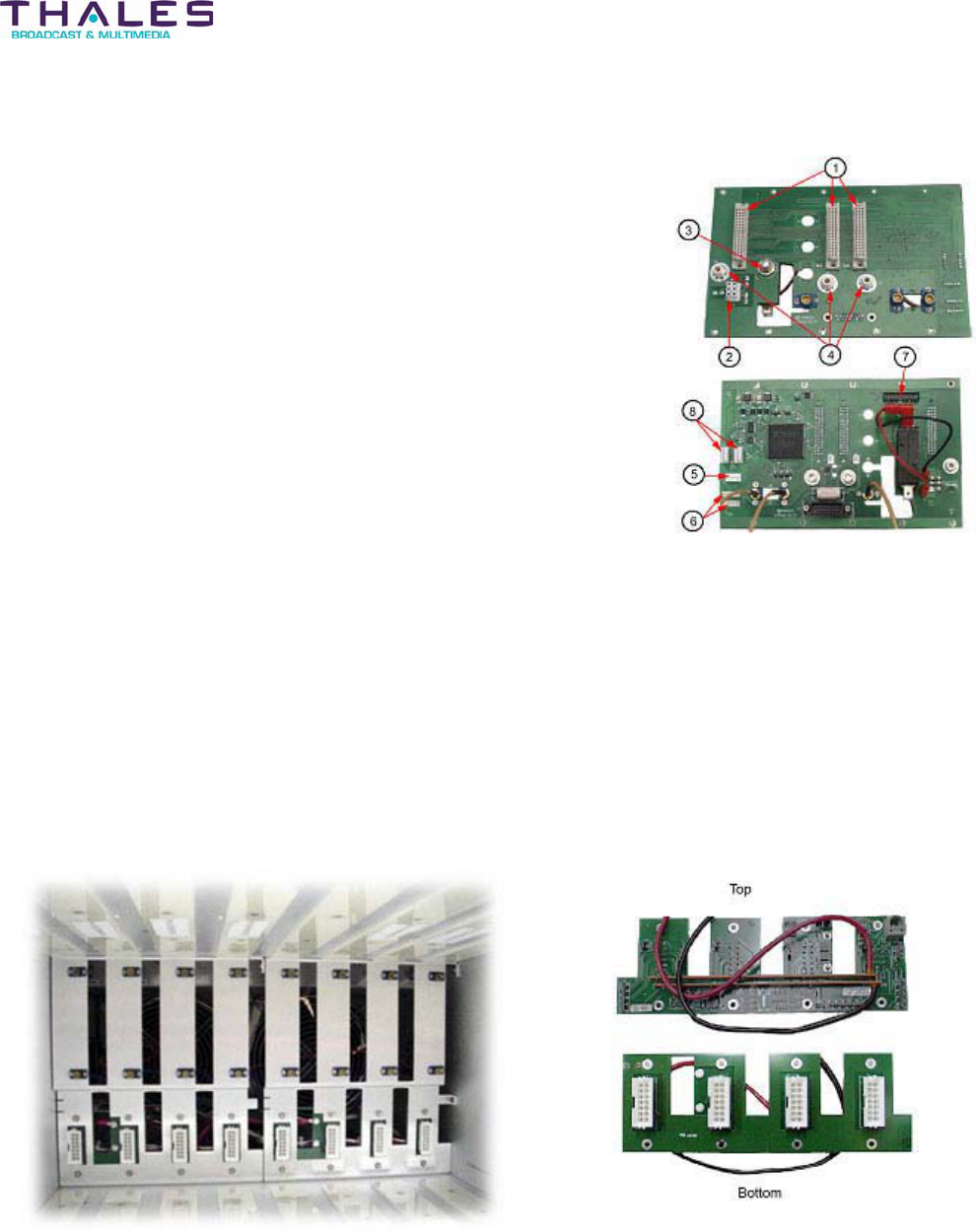
16.3 PA Backplane
The PA Modules are electrically and physically connected to the PA Backplane when plugged
into the Chassis assembly. The PA Backplane contains float-mounted, blind-mating receptacles,
and blind-mating headers for module alignment. The PA Backplane provides +48VDC and
ground for the PA Module segments. The PA Backplane also contains RS485 multidrop
communication connectivity used by the PA Module assemblies. A two-position Dual Inline
Package (DIP) switch located on the PA Backplane is used to enable or disable control and
diagnostic access via the RJ11 connector located on the front panel of the PA Modules.

Backplane/Interface Boards - 124 -
®
Affinity LBD-200C-N1 Transmitter
Product Manual
16.4 Rear Panel Interface
Located on the rear panel, the Rear Panel Interface
board allows access to the control and diagnostic
signals within the unit.
J1 is a 14-pin terminal block that allows diagnostic
and monitoring pigtail wires to be clamped via the
screw lock-downs. This connector provides fault
indication status for each sub-assembly within the
transmitter system.
J3 - (N/A)
J4 - (N/A)
J1 Control and Diagnostics connector pin-outs
Backplane/Interface Boards - 125 -
®
Affinity LBD-200C-N1 Transmitter
Product Manual
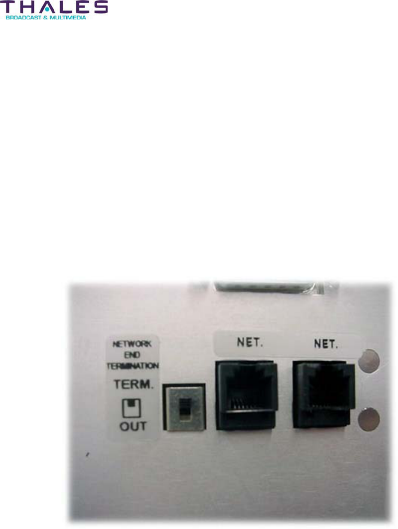
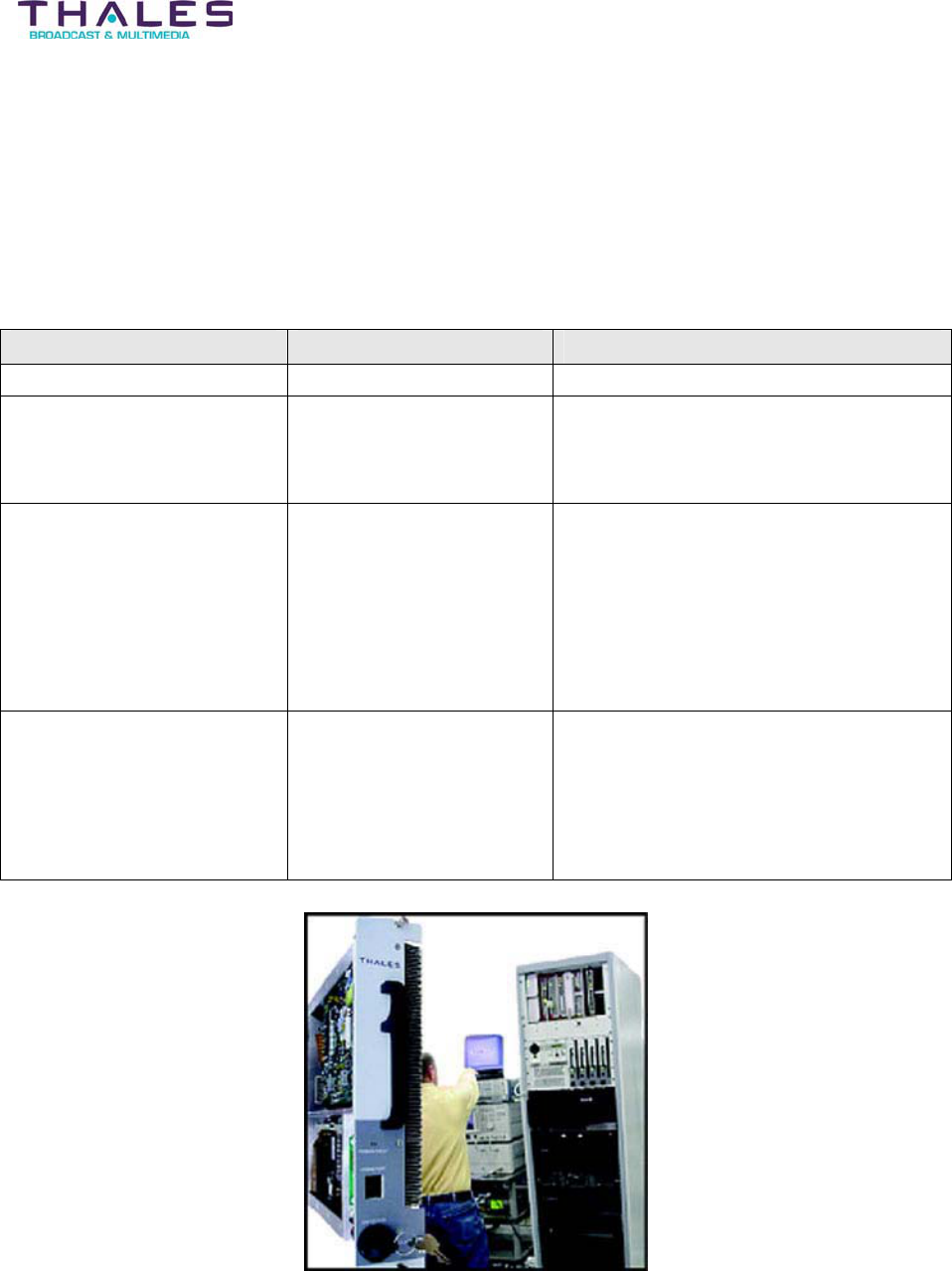
16.5 RS-485 Communication Board
An RS-485 Communication Board is mounted to the inside rear of the Driver Section. The
board monitors the RS-485 communication traffic on the system bus. A common
computer/master control station can monitor up to 32 RS-485 devices on the network.
The RS-485 Communication Board is equipped with two RJ11 6-pin telephone type receptacles.
The cables used to daisy chain (parallel) the RS-485 devices to the host are shielded double
twisted pair.
A mini double-pole double-throw (DPDT) dipswitch labeled NETWORK END TERMINATION is
accessible on the RS-485 Communication Board from the back panel of the Driver Section. In
an RS-485 network, all RS-485 devices in the daisy chain series, with the exception of the last
RS-485 device in the network, have the dipswitch set to OUT. The last RS-485 device in the
network has the switch set to TERM. Placing the switch in TERM terminates the communication
bus with the required impedance.
RS-485 Communication Board
Backplane/Interface Boards - 126 -
®
Affinity LBD-200C-N1 Transmitter
Product Manual
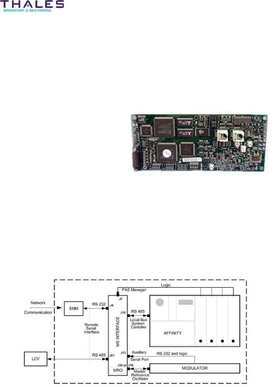
16.6 Master Support Interface Board
Overview
The Master Support Interface (MSI) Board assembly performs several functions within the
Affinity transmitter.
x Interface to external management
system.
x Control and monitoring of the plug-in
modules, via communication and
electrical interfaces
x Management (control, fault
notification) of modulator
x On-board Master Reference Oscillator
(optional, for DVB-H applications)
x Fast response PA module (Amplifier
plug-in) protection
Hardware systems
The MSI hardware performs various hardware functions and provides a platform for the
management of the internal transmitter components. The circuitry contains a primary
microcontroller (Main MCU), a primary programmable logic device, or CPLD (Main CPLD), and
an MCU and CPLD dedicated to an auxiliary serial port provided by the transmitter (Port MCU
and Port CPLD). Other key circuitry includes a Master Reference Oscillator system, Power
Amplifier Segments manager, Fast ALC Reduction circuit, and Remote and Local serial busses.

Backplane/Interface Boards - 127 -
Affinity® LBD-200C-N1 Transmitter
Product Manual
Remote Serial Interface
External high-level management systems connect to the Affinity® transmitter using the
transmitter Remote RS-485 interface. The electrical interface consists of: an RJ-11 jack located
on the Affinity® rear panel, a wire harness located inside the Affinity® chassis, and the RS-485
transceiver circuit located on the MSI circuit board assembly. SNMP management is provided
through the Omnitronix SNMP Device Server.
Local Bus System Controller
The MSI acts as a master on the Local RS-485 network located inside the Affinity® chassis. As
the master on the network, the MSI sends query and command messages to the slave devices
on the Local network, and receives responses from the slave devices. The Upconverter plug-in
is a slave device.
The Local bus support circuitry consists of:
Auxiliary Serial Port
An RS-232 transceiver, and dedicated MCU and CPLD circuits are provided on the MSI to
support an auxiliary RS-232 serial port (aux port). The port system consists of the transceiver
and controller circuits on MSI connector J13, and harnessing to the rear panel DB-9 male
connector. The auxiliary serial port is typically used to interface a modulator to the Affinity®
transmitter.
Master Reference Oscillator
The Master Reference Oscillator (MRO) system on the MSI receives a 10 MHz reference input
on MSI SMA connector J17. The MRO phase-locked loop (PLL), which contains an on-board
VCO, locks to the reference input. The VCO output signal is fed to two SM connectors, J16 and
J19. These are used to feed the Affinity® Local Oscillator and the modulator (optional). A
tracking mechanism is provided that follows the control voltage applied to the VCO. Should the
10 MHz reference input be removed, the tracking holds the VCO at the last stable position of the
VCO. This helps maintain the transmitter on frequency, even after loss of reference input.
PAS Manager
The Power Amplifier Segments (PAS) are contained in the same chassis as the MSI. This group
of amplifiers is called a “quad”.
The PAS Manager of the MSI protects the amplifiers from damage that could occur following
failure or removal. When an amplifier fails, the output power of the transmitter is reduced. The
transmitter ALC will attempt to correct the reduction in power by increasing the drive level
applied to the remaining amplifiers. Since this can result in overdriving the remaining amplifiers
and potentially damaging the device(s), the PAS Manager reduces the ALC level to a factory-
calibrated level. The transmitter power is reduced predictably (Fast ALC Reduction). The PAS
status signals are monitored on connector J7 of the MSI. Failed PAS location numbers are
stored in a CPLD register and read by the Main MCU for monitoring and fault notification.

Backplane/Interface Boards - 128 -
Affinity® LBD-200C-N1 Transmitter
Product Manual
Firmware Systems
The MSI contains four firmware programs: the Main MCU program, the Main CPLD program,
the Port MCU program, and the Port CPLD program. Interaction of the various firmware
programs is described below.
Main MCU Firmware
The Main MCU program (main firmware) is the most complex of the four programs. This
program is responsible for supporting the Local and Remote serial interfaces, MRO, and PAS
Manager, as well as passing commands to the Modulator, and receiving fault notifications from
the Modulator.
Remote Serial Bus Support
The main firmware receives TNET protocol Remote serial commands and requests. Commands
may be issued by using the Omnitronix SNMP Link SL81 management device. The commands
may be used to change the values of calibration variables stored in MSI non-volatile memory.
For a list of these variables, refer to the SNMP document.
Commands may also be issued to change the settings and behavior of the Modulator. Refer to
SNMP document for a list and description of the available Modulator commands. The main
firmware is stored in flash memory. The firmware may be updated using a terminal emulator to
issue updated commands to the transmitter, and to transfer the updated firmware file to the
transmitter.
Status of the Affinity® transmitter is collected by means of status queries sent to the MSI
Remote serial port. The MSI responds to these requests with a response message in a
predefined format, containing values of monitored variables. In transmitters having an internal
SNMP Device Server, the Device Server repeatedly polls the status of the Affinity® transmitter
with status queries sent to the MSI.
Local Serial Bus Support
The MSI Main MCU, through firmware, implements a master device on the Affinity® internal
Local serial bus. The master device issues requests and commands to the Upconverter on the
bus, which is a slave device (i.e. this node cannot issue a request or command, but can only
receive requests/commands and respond). Through frequent Local bus queries/responses, the
MSI collects the status of the Upconverter. In addition, the MSI can send commands to the plug-
in causing changes in operation such as: changing the operating channel, or setting the system
to STANDBY or ON AIR.
Master Reference Oscillator Support
The MSI main firmware monitors and controls the on-board Master Reference Oscillator (MRO).
The main firmware monitors the MRO PLL VCO control voltage using an A/D converter. The
MSI uses the measured voltage to determine a second control voltage to be applied to the PLL
that follows the MRO PLL VOC control voltage. A D/A converter on the MSI generates the
output. As the VCO control voltage changes slowly with time, the D/A voltage tracks the VCO
voltage. If the 10 MHz reference input to the transmitter is removed, the tracking voltage is

Backplane/Interface Boards - 129 -
Affinity® LBD-200C-N1 Transmitter
Product Manual
frozen by the main firmware thus minimizing disturbance to the transmitter. When the input is
reapplied, the tracking resumes.
PAS Manager Support
In the Power Amplifier Segment (PAS) quad system, the MSI monitors two signals, PAS_fault
and PAS_presence, for each PAS. The monitoring is performed in the Main CPLD in a system
called the PAS Manager. The failed PAS is detected by the MSI main firmware by reading the
registers in the Main CPLD.
The MSI main firmware uses a calibration variable QUAD_MASK to inform the MSI CPLD of the
number of installed PAS modules. This is necessary to set the proper ALC reduction for the
given number of PAS.
Auxiliary Port Management
The MSI Auxiliary Serial Port (aux port) is used to monitor and control a device connected to the
Affinity® transmitter, such as a modulator. The Port MCU handles port management; however,
the commands and requests for status of the modulator originate in the top-level management
system and pass through the Main MCU as TNET serial messages. The Main MCU copies the
command or status request from the TNET message and passes the request to the Port CPLD,
which sends the appropriate control or monitoring message to the managed port device.
Refer to SNMP document for a list and description of the variables managed in the auxiliary
equipment connected to the Auxiliary Port.
Port MCU Firmware
The Port MCU is dedicated solely to the management of a device connected to the Auxiliary
Serial Port. Equipment such as a modulator may be connected to the aux port. In the factory,
the firmware program appropriate to the end-user’s purchased equipment is loaded in the Port
MCU.
The Port MCU periodically reads fault alarms for various modulator systems from the modulator
and writes the conditions of the systems (pass/fail) to the Port CPLD. The alarm status is
available to the Main MCU for fault notification to the top-level management system.
At any time, the top-level management system can issue a command to the modulator. The
command is received by the Main MCU and passed through the Port CPLD to the Port MCU.
The Port MCU develops the corresponding message with arguments given in the original
command, and sends messages to the modulator connected to the aux port.
Backplane/Interface Boards - 130 -
Affinity® LBD-200C-N1 Transmitter
Product Manual
System Configuration
During factory set-up and test, the various transmitter systems under the control of the MSI are
configured, and settings stored, in the MSI non-volatile memory. Some configuration settings
are used to enable and set-up optional resources of the MSI. The settings are stored in
“personality” variables. In general, users should not change variables, but the user can read
back the values of the variables to recall the available MSI resources. The variables are briefly
described below. For a more detailed description of the personality variables, refer to the SNMP
document.
x On Board Resources Personality (OBR_PERSON) – enables or disables MSI
systems such as PAS Manager for quads and MRO.
x Local Serial Bus Personality (LOCAL_PERSON) – enables or disables local serial
communications with the plug-in modules.
x Auxiliary Serial Port Personality (PORT_PERSON) – enables or disables the Aux
Port system.
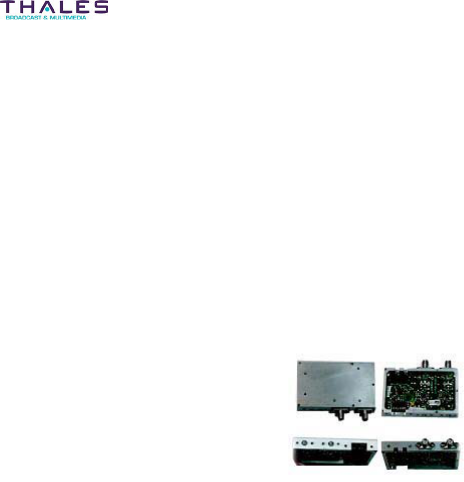
16.7 True RMS Detector Module
The signals coming from the directional coupler feed the
True RMS Detector Module with both the forward power
and reflected power proportional to the transmitter output.
The input attenuator matches the directional coupler port
and level to the detector.
The RMS Detector Module is based on a true RMS
detector-chip that provides linear RF detection with high
sensitivity. The log function of the detector allows for the
measurement of the rms power independent of the peak-
to-average ratio of the specific waveform of the
transmitting signal. Temperature compensation and fault
detection are provided with the circuit.
Backplane/Interface Boards - 131 -
®
Affinity LBD-200C-N1 Transmitter
Product Manual
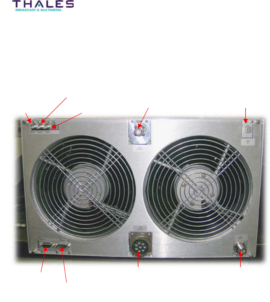
16.8 Sub-Chassis Rear Panel
Rear Panel Connectivity
Amplifier Chassis
Reflective Sam
p
le
Fan ACRF Out
p
ut
Forward Sample Feedback Sam
p
le
PAS Monitor
PAS Command 48 Volt DC Input RF Input
48VDC Input: The DC Input provides the power supply requirements for the PA Modules
RF Output: This is the 50-ohm UHF output signal connection to the RF System. (Female N-
type connector)
RF Input: Allows RF input from the exciter (-18dBm typical). The connector is 50-ohm BNC.
Fan AC: Provides the AC source to power up the Amplifier Chassis fan assemblies
Forward Sample: This input is for the RF sample feedback from the RF system to drive the
local power meter.
Reflective Sample: This input receives the Reflected RF signal feedback from the RF system
to drive the local Reflected power meter.
Backplane/Interface Boards - 132 -
®
Affinity LBD-200C-N1 Transmitter
Product Manual
Feedback Sample: This BNC connector is the output feedback signal of the transmitter. This
signal is used to calculate its correction.
PAS Command: This output (9-pin DB female connector) is used to transmit operational
commands to the Amplifier Chassis.
PAS Monitor: This output (9-pin DB male connector) transmits operational status data to the
Driver Section.
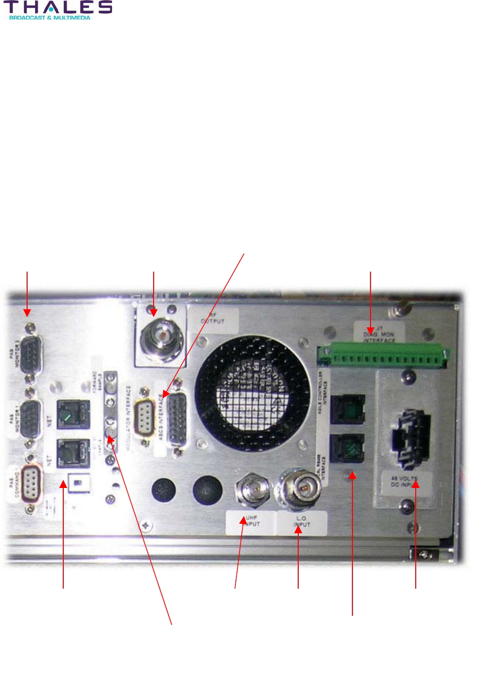
Driver Chassis
PAS Command,
PAS Monitor 1,
PAS Monitor 2
Modulator Interface,
ABCS Interface
RF Output Diagnostic Monitor
Interface (J1)
NET, NET
Network End Termination
Forward Sample,
Reflective Sample
UHF Input LO Input
Agile Controller
Interface,
Local RS485
Interface
48 Volts DC Input

Backplane/Interface Boards - 133 -
®
Affinity LBD-200C-N1 Transmitter
Product Manual
16.8.1 Exciter to UCA Cabling and System Interconnects
This section explains cabling and interconnections for the LBD-200C-N1 transmitter. Refer to
the Automatic Backup Control System (ABCS) & Site Management Module (SMM) descriptions
within the BTS control chassis manual for additional interconnections of the agile transmitter
and remote SNMP management systems.
UCA Sub-Chassis Front Panel:
Connect the LO output of the LO Plug-In module to the LO input of the UCA with the SMA male-
to-male semi rigid jumper.
Transmitter:
Refer to the cabling diagram, which depicts a photo of the rear panel interconnections.
RF Filter - 134 -
®
Affinity LBD-200C-N1 Transmitter
Product Manual
17 RF Filter Description
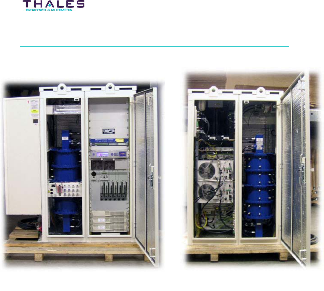
RF Filter (Rear view)
RF Filter (Front view)
Phone Systems - 135 -
®
Affinity LBD-200C-N1 Transmitter
Product Manual
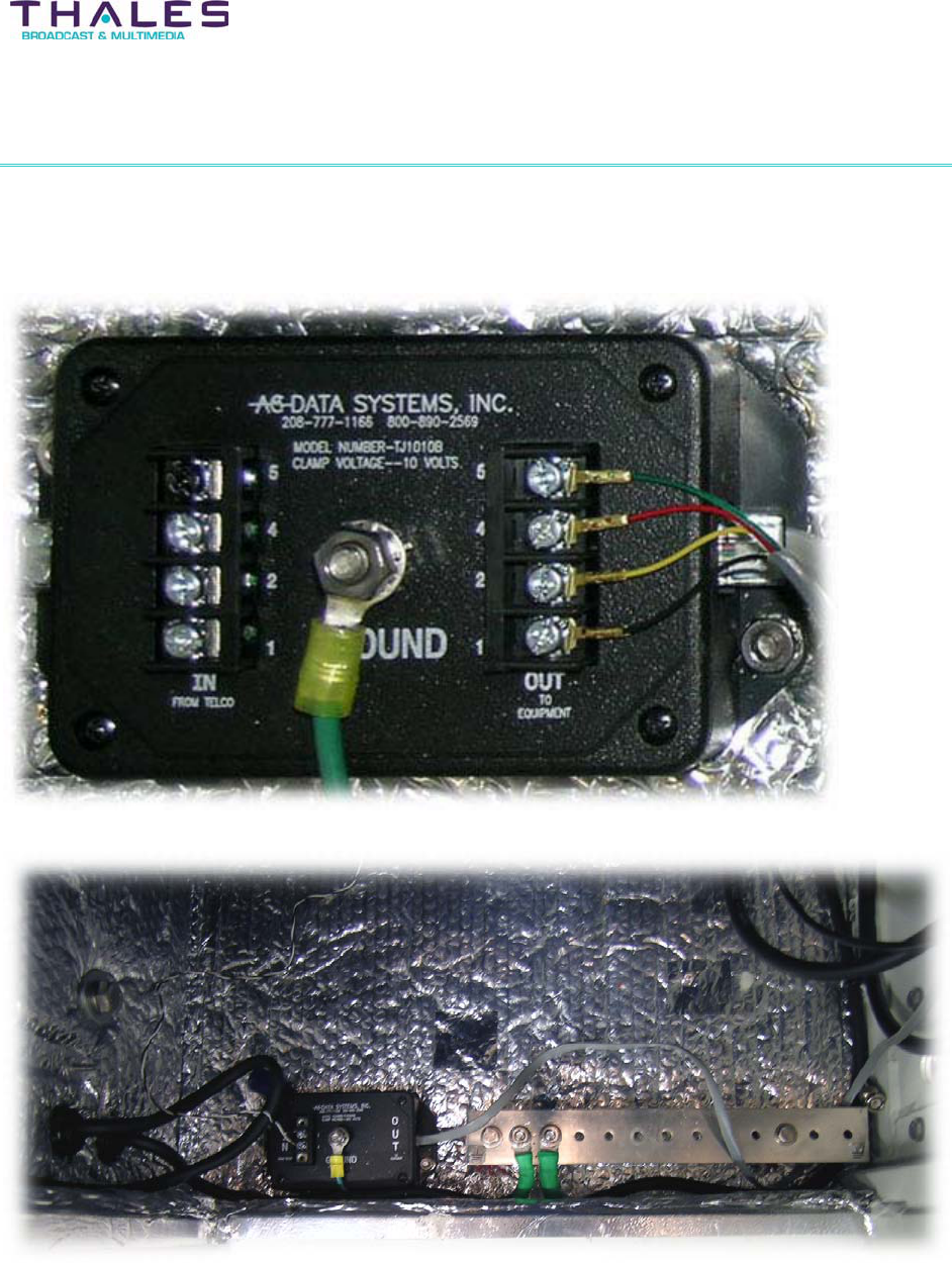
18 Phone System Description
Transmitter Cooling - 136 -
®
Affinity LBD-200C-N1 Transmitter
Product Manual
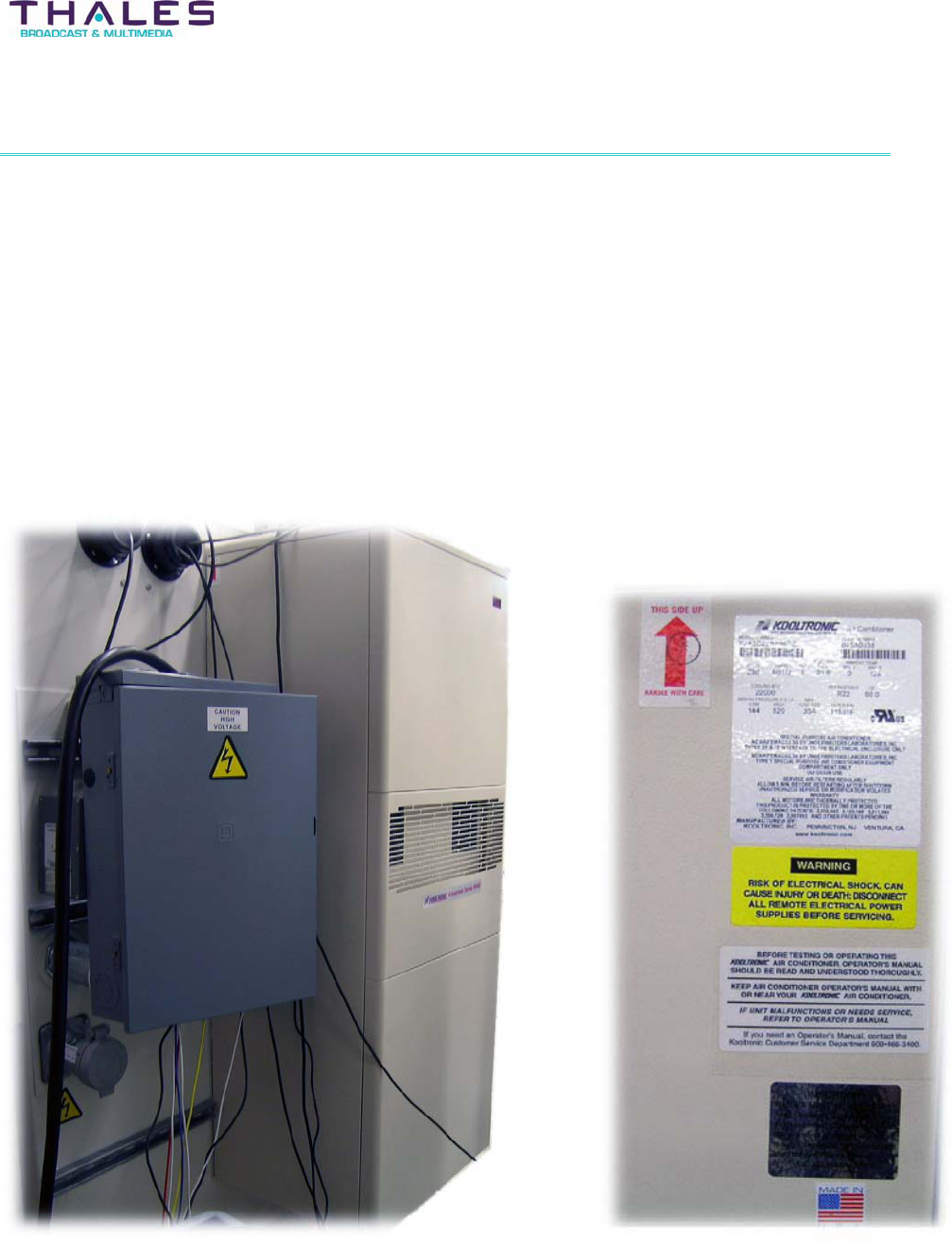
19 Transmitter Cooling Description
The Affinity® LBD-200C-N1 transmitter incorporates a combination of forced ambient air-cooling
and cabinet air conditioning systems. In the ambient system, air enters through the front of each
chassis and exits the rear. Amplifiers use folded-fin heatsink technology for increased cooling
efficiency. The Upconverter chassis uses a similar cooling arrangement with low volume fans for
the lower associated heat dissipation. Accompanying the forced air-cooling systems is the
enclosure air conditioning system sized according to the heat load expected by the transmitter
and ancillary equipment.
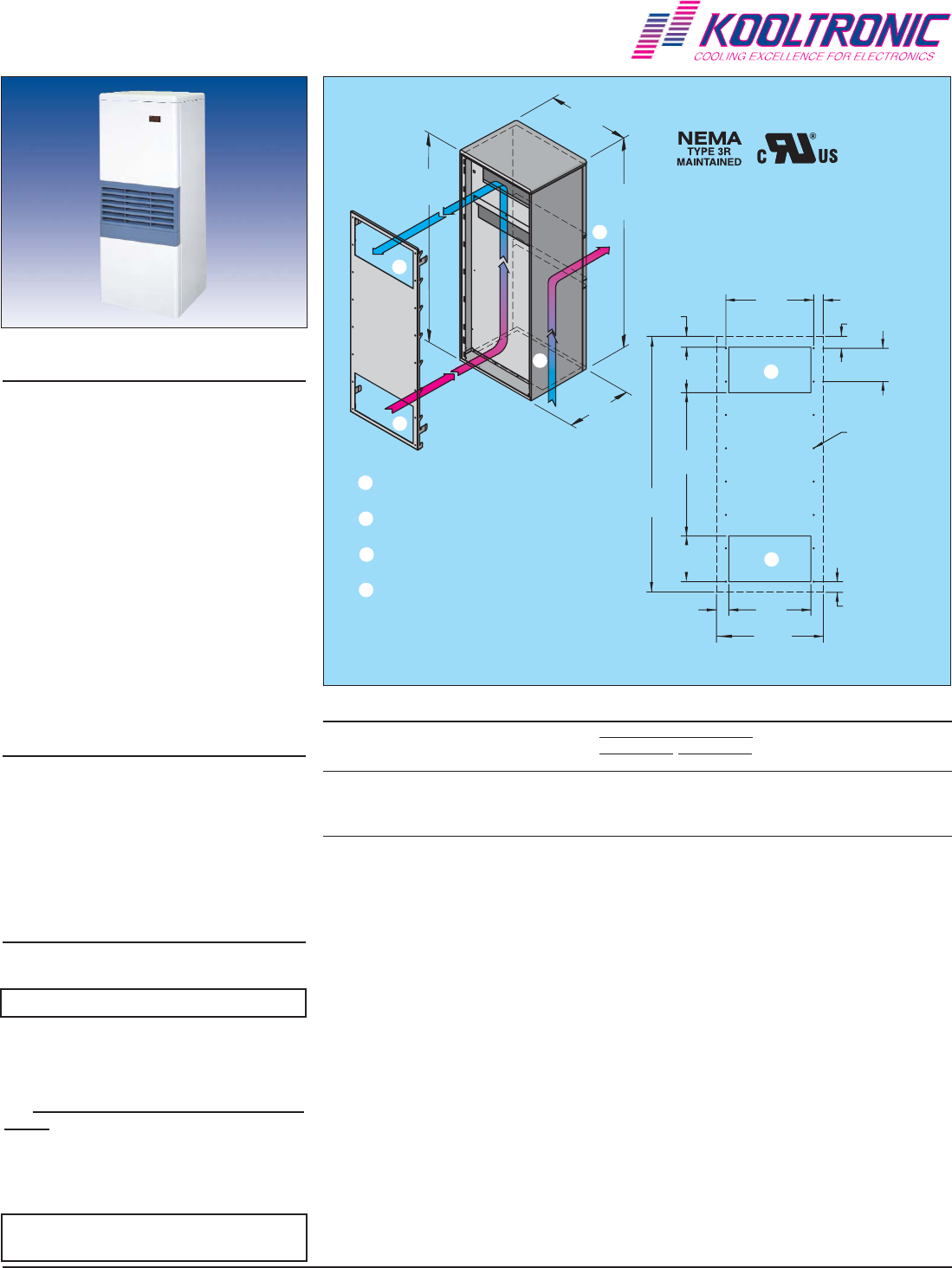
19.1 Cabinet Air Conditioning Systems
K2A3C18RP55R R22 Recognized 18000 125 0 51.7 -17.8 230 60 21.6 5.3/8.8
K2A3C20RP55R R22 Recognized 20000 125 0 51.7 -17.8 230 60 21.6 5.3/8.8
K2A3C22RP55R R22 Recognized 22000 125 0 51.7 -17.8 230 60 21.6 5.3/8.8
UL/CUL Ambient Temp. ***
Listed or BTU/H °F °C Cooling Heating
Model Refrigerant Recognized Rating Max. Min. Max. Min. Volts Hz Amps Amps
TECHNICAL DATA
* Rating shown is for operation at maximum ambient temperature.
** Optional Single Enclosure Heater/Double Enclosure Heater
ADVANTAGE RP55 SERIES AIR-COOLED
PANEL-MOUNTED AIR CONDITIONERS
ACCESSORIES AND OPTIONS*
QCooling Effect Detector
QEnclosure Heater
QFilter Recoating Adhesive
QFilters for replacement
QInternal corrosion protection
QPower Loss Delayed Compressor Start
QSpecial paint finishes
*See opposite side for more information.
POPULAR MODELS ARE
STOCKED AND READY TO SHIP
HOW TO ORDER
Specify model number. NOTE: Accessories
and Options may affect model number,
contact KOOLTRONIC for information.
For assistance in model selection, refer to
the Air Conditioner Sizing and Selection
Guide, contact KOOLTRONIC, or use
one of our design aid software programs,
available FREE.
CALL 1-800-321-KOOL (5665)
or FAX 609-466-1114
APPROXIMATE WEIGHT
298 lbs. [135.5 kg]
STANDARD FEATURES
Textured Baked Powder Finish
Built-in Condensate Evaporator
Low ODP Refrigerant
Closed-Loop Cooling
Crankcase Compressor Heater
Digital Temperature Display
EMI/RFI Suppressor
Head Pressure Control Switch
Heavy-duty Steel Enclosure
Low Ambient Kit
Low Temperature Control Thermostat
M/TAB Mounting System
NEMA3R Rating Maintained (UL50)
Permanent Filters
Six Foot [1.8m] (minimum)
SJT 3-wire Cord
UL/CUL Recognized
Kooltronic, Inc., 30 Pennington-Hopewell Road, P.O. Box 240, Pennington, NJ 08534-0240
Tel: (609) 466-3400 Fax: (609) 466-1114 Internet: www.kooltronic.com E-Mail: sales@kooltronic.com
MOUNTING PLAN
55.62
[1412.7mm]
21.99
[558.6mm]
17.34
[440.4mm]
56.20
[1427.5mm]
FILTERED CONDENSER
AIR INLET (Ambient Air In)
CONDENSER OUTLET
(Warm Ambient Air Out)
WARM AIR RETURN
FROM ENCLOSURE
COOL AIR OUTLET
TO ENCLOSURE
❶
❸
❷
❹
❶
❷
❹
❸
❹
❸
Dimensions, inches [metric], are for reference only and are subject to change.
19.25
[489.0mm]
2.43
[61.7mm]
10.00
[254.0mm]
31.44
[489.0mm]
2.34
[59.4mm]
10.00
[254.0mm]
1.99
[50.5mm]
18.00
[457.2mm]
7.31
[185.7mm]
2.68
[68.1mm]
1.37
[34.8mm]
(16) .281 [7.0mm]
DIA. HOLES
21.99
[558.6mm]
56.20
[1427.5mm]
UNIT MUST BE 4" MINIMUM
ABOVE FLOOR FOR FILTER
ACCESS
rp55.qxd
8/23/05
K2A3C20RP55R

DESCRIPTION
At last - air conditioners designed specifically for cooling electronic enclosures that can be used for both indoor and outdoor applications right out of the
box!
No more bulky unattractive weather hoods... No more worries over what options to specify for outdoor applications.
Expertly designed and crafted, the ADVANTAGE Series boasts a stylish appearance with rounded edges, no visible hardware and a textured baked
powder finish to blend easily with contemporary enclosure designs.
Servicability has been made easier by incorporating a “knock-down” sheetmetal design which provides quick access to internal components.
Standard features include heavy duty galvanized steel construction with baked-on powder paint, environmentally friendly refrigerants, built-in
condensate evaporator, thermostatic low temperature control and EMI/RFI Suppressor. These air conditioners are available in capacities from
1,000 to 22,000 BTU/H in seven heights, all utilizing the exclusive KOOLTRONIC M/TAB integral mounting system.
KOOLTRONIC also designs and manufactures a variety of Air Conditioners to meet unique specifications. We invite your inquiries about our
modification and custom-design capabilities.
STANDARD FEATURES
CLOSED-LOOP COOLING: The enclosure interior airflow system is isolated from the ambient airflow system. Ambient air can not invade the cool,
dehumidified sensitive component compartment.
BALL-BEARING MOTORS: All fan motors are UL/CSA Recognized and include automatic-reset thermal overload protection and double-sealed or
double-shielded precision ball bearings. Special permanent lubricants in the tube axial fans perform over a broad temperature range: -20°F [-28.9°C] to
250°F [121.1°C].
RUGGED CONSTRUCTION: Precision-engineered heavy gauge steel construction of all cabinets and blowers insures Air Conditioners will stand up
under tough applications.
TEXTURED BAKED POWDER FINISH: Durable, baked-on textured beige powder finish is standard. Other finishes are available.
POWER: Available in 230 VAC, 50 Hz or 60 Hz.
REFRIGERANT: Low Ozone Depleting Potential (ODP) R22 Refrigerant is used in all Advantage RP55 Series Air Conditioners and are being con-
verted to CFC-free R134a Refrigerant as compressors become available. Consult KOOLTRONIC for status at time of requirement.
PERMANENT FILTERS: Multi-layer grid of sturdy, corrugated aluminum in an aluminum frame. May be reused after washing off accumulations and
spraying with A-16 Recoating Adhesive.
CONDENSATE EVAPORATOR: Built-in Condensate Evaporator eliminates need for draining condensate under normal operating conditions. May
not be adequate in extremely high humidity with open or leaky enclosure. Overflow condensate drain fitting and hose are included.
LOW AMBIENT KIT: Maintains sufficient operating pressures when ambient temperatures drop below 50°F [10°C]. Includes a compressor heater and
pressure actuated condenser blower cycling control.
LOW TEMPERATURE CONTROL: Thermostatic Low Temperature Control prevents over-cooling and provides energy-efficient operation.
EMI/RFI SUPPRESSOR: EMI/RFI Suppressor minimizes transient line spikes during on/off cycling.
CRANKCASE COMPRESSOR HEATER: 240V heater attached to the compressor crankcase to maintain appropriate temperatures during cold
operating conditions.
HEAD PRESSURE CONTROL SWITCH: A control device to minimize compressor cycling and prevent evaporator coil icing.
POWER CORD: All models have six foot [1.8m] SJT-type 3-wire power cords with appropriate plugs.
INSULATION: All cold components, lines and the evaporator compartment are insulated with high-performance insulation for maximum efficiency.
GASKETING: All units are fully gasketed for tight, leakproof installation, in compliance with the NEMA 3R Enclosure Rating.
QUALITY ASSURANCE: Refrigeration system components are kept sealed until charged with refrigerant; all brazed joints are thoroughly leak-tested;
each unit is functionally tested before shipment.
INSTALLATION: Detailed Installation and Operator's Manual, with drawings, mounting plan and spare parts list is included with each unit.
UL/CUL RECOGNIZED: All Advantage RP55 models are UL/CUL Recognized. All Recognized models are available as Listed at added cost.
ACCESSORIES AND OPTIONS**
FACTORY-INSTALLED OPTIONS:
COOLING EFFECT DETECTOR: A thermostat is mounted inside the cabinet and attached to a sensor in the warm air return. When the air
temperature increases to the set point, a signal is sent to a terminal block. User-installed wiring from the terminal block to local and/or remote warning
devices (light, bell, siren, etc.) can be for normally open or closed operation.
Append letter "B" to Part No.
ENCLOSURE HEATER: 240V fin strip heater, installed singly or ganged, used to maintain desired internal enclosure temperature, under cold oper-
ating conditions.
Single Heater, append letter "F" to Part No.
Double Heater, append letter “G” to Part No.
**Contact KOOLTRONIC for information.

ACCESSORIES AND OPTIONS** (continued)
INTERNAL CORROSION PROTECTION: For corrosive or other hostile environments, special coating material is applied to copper lines, coils
and other parts subject to damage.
Append letter "H" to Part No.
POWER LOSS DELAYED COMPRESSOR START: Protects the compressor from possible damage due to harmful short cycling, by initiating an
“off” period before resumption of normal operation. Generally air conditioners require several minutes off for compressor protection after power inter-
ruptions of any type. These power interruptions can include power failures, opening of interlocked access doors, and cases where a thermostat activates
the compressor in less than a few minutes. This option is particularly recommended for applications where frequent, brief power failures occur, inter-
locked cabinet doors are utilized, or where the cabinet internal loads fluctuate across a wide range.
Append letter "Y" to Part No.
SHORT CYCLE PROTECTOR: Protects the compressor from possible damage due to harmful short cycling, by initiating an "off" period before
resumption of normal operation. Generally air conditioners require several minutes off for compressor protection after power interruptions of any type.
These power interruptions can include power failures, opening of interlocked access doors, and cases where a thermostat activates the compressor in
less than a few minutes. This option is particularly recommended for applications where frequent, brief power failures occur, interlocked cabinet doors
are utilized, or where the cabinet internal loads fluctuate across a wide range.
Append letter "Y" to Part No.
SPECIAL PAINT FINISHES**
PAINTED METAL GRILLE**
Append letter “Z” to Part No.
CUSTOMER-INSTALLED OPTIONS:
FILTERS FOR REPLACEMENT: All KOOLTRONIC filters consist of a multi-layer grid of sturdy corrugated aluminum, securely held in a one-piece
aluminum frame. Filters are required wherever air is drawn into an electronics enclosure or related cooling equipment to keep internal parts as clean as possible.
A non-drying adhesive coating traps a high percentage of particulate matter. These washable, reusable filters are designed to last the life of the cooling
unit. Replacements are available for those which become damaged or otherwise non-serviceable.
Part No. 11631F (11.63 x 21.63 x 0.38 [295mm x 321mm x 10mm])
FILTER RECOATING ADHESIVE: This compound is a superior product for recoating all permanent filters after washing. The adhesives penetrate
dirt layers to keep the filter surface tacky for longer effective performance between washings.
Part No. A-16 - one pint container.
**Contact KOOLTRONIC for information.
Kooltronic, Inc., 30 Pennington-Hopewell Road, P.O. Box 240, Pennington, NJ 08534-0240
Tel: (609) 466-3400 Fax: (609) 466-1114 Internet: www.kooltronic.com E-Mail: sales@kooltronic.com

Affinity® Control Systems - 140 -
®
Affinity LBD-200C-N1 Transmitter
Product Manual
20 Affinity Transmitter Control Systems
The upconverter amplifier (UCA) control system (driven by multiple microprocessors) monitors
and controls all of the transmitter sub-assemblies, and provides transmitter status information to
the operator.
A user-friendly man/machine interface is provided by:
x A front-panel control interface for menu driven commands (select, enter, escape, &
exit buttons).
x A front panel LCD screen located on the driver module providing transmitter status
information (status of transmitter, output power, power supply, local oscillator, and
upconverter).
The transmitter safety system is hard wired, which allows for real-time processing, and is
independent of the control system.
20.1 Automatic Control Systems and Monitoring
Automatic control systems protect the transmitter against VSWR problems and excessive air
input temperatures by affecting successive restarts---first at the nominal power---then at –3dB
while maintaining the transmission quality at the level obtained at nominal power output.
Approximately, a 30-second delay will occur between the restarts. The transmitter is
automatically shut down if the fault persists.
The transmitter is also protected by a safety system that causes amplifier module shutdown
(due to excessive transmitter temperature, etc.). Monitoring of operational parameters, alarms,
power output, VSWR, status of amplifiers, drivers and safety loops are available.
20.2 Status Monitoring and Control System (SMCS)
The Omnitronix SL81 Status Monitoring and Control System (SMCS) is provided for use with
the Affinity® LBD-200C-N1 transmitters. The SMCS is a rack-mounted unit located within the
transmitter cabinet. It provides a web interface and an SNMP agent for remote control. Remote
access to the SNMP agent is available through a GSM connection or via dial-up modem and a
PSTN line. All events and faults are stored in a logbook with date and timestamps.
20.2.1 SMCS Functions:
Controls
The SMCS has the ability to access the On (transmit), Off (standby), and Reset commands.
Other operational commands, monitoring and safety controls, and diagnostic help system are
available. The SNMP manager program can be used to browse the MIB of a connected device
and select variable(s) to be modified.

Affinity® Control Systems - 141 -
Affinity® LBD-200C-N1 Transmitter
Product Manual
Fault Log System
The fault log system within the SMCS records transmitter status changes (using time and date
coding) and enables detection and identification of faulty sub-assemblies. This event data is
stored in the history log in non-volatile memory.
The parameters in the history log can be sorted and viewed several ways including: view by
general chronological event and view by parameter. This information can be printed and
exported from the SMCS for use with a typical database management system for further
analysis.
Remote Control
The SNMP remote control system of the SMCS requires the use of a third-party element
management system. It can be configured with either a dial-up modem interface or a GSM
connection. All functionality of the local SMCS system is available to a user using the remote
version (including control commands). Access to the SNMP agent for either writing and/or
reading is organized by means of different user profiles defining the individual access rights.
The SNMP TRAP operation is used to asynchronously send event information to the remote
manager. The agent generates a TRAP message when one or more of the predefined
conditions occur. The link between events and traps are configurable. The SNMP agent also
integrates the SMTP protocol, allowing it to send email on events.
External Contact Closure Monitoring
In addition to internal transmitter system monitoring, the SMCS system allows the monitoring of
several external contacts and alarm signals. The SMCS system is provided with a peripheral
input/output system (PIOS) that provides the station the capability to monitor up to twelve
contact closures. The system has three dedicated ports for fire, security, and environment. The
user can name the remaining external contact closures through the GUI. This provides the
flexibility to monitor anything at the transmitter station that can be interfaced to the contact
closures provided in the PIOS (tower lights, generator status, UPS alarm, etc.).
Contact Closure panel

Affinity® Control Systems - 142 -
Affinity® LBD-200C-N1 Transmitter
Product Manual
Omnitronix SNMP-Link SL81 Manual here

Quick Start Procedure - 143 -
Affinity® LBD-200C-N1 Transmitter
Product Manual
21 The Affinity® Quick Start Procedure
Each Thales transmitter is factory calibrated, and requires only a minimum start-up procedure to
ensure proper operation. The appropriate steps for the installation of the Affinity® transmitter
system and its ancillary equipment must have been performed prior to initiating this procedure.
Please consult the installation and cabling sections of this manual before powering up any
equipment. Verifying that all cables and electrical connections are in place is crucial. Read this
section entirely, along with the calibration section, prior to beginning the transmitter power
initiation process.
1. Start by ensuring that all of the amplifier modules are turned off via the front panel key
switches.
2. Apply AC power to the UPS system; follow the manufacture’s turn on guidelines.
3. Apply AC power to the site management system; follow the manufacture’s turn on
guidelines.
4. Apply AC power to the satellite receiver; follow the manufacture’s turn on guidelines.
Ensure a proper ASI feed is available to the Sirius DVB-H Exciter.
5. Switch on AC power to the Affinity® Upconverter amplifier chassis(s). Observe that the
AC fan has begun to operate (fan noise will be heard).
6. Turn on the 48V Front-End Power Supplies; all plug-in modules should indicate proper
DC output via their LED display. Also, observe that the driver sections including the
multi-output Power Supply Plug-In and Upconverter have begun their initialization (a
small time lag is normal -- under 5 seconds typical).
7. Switch on the Sirius DVB-H Exciter. Using the exciter front panel MMI, turn off adaptive
pre-correction if enabled and place in flat response mode (first go to frozen mode then
go to flat mode).
8. If available, use a spectrum analyzer to verify the exciter output level -18dBm r 1dB.
Adjust if required. Observe the exciter output, perform cancellation of LO or image
rejection via local MMI or SIRUIS setup GUI interface (this is a factory calibration and
should not be required).
9. Connect exciter output to the Upconverter amplifier chassis (UCA) UHF input.
10. Ensure 1GHz Local Oscillator connection via exciter and UCA.
11. Connect power meter to output coupler.
12. Ensure that the transmitter output is connected to an appropriate sized 50-ohm station
load. Note: the return loss of the load should be greater than 15 dB at minimum.
13. Switch on all power amplifier (PA) front panel key switches while observing the power
meter.
14. Using a power meter, ensure proper power output. Also, if available, observe channel
spectrum output shoulder performance; shoulder should not exceed -29dBc from flat top,
RES BW 30kHz VBW 3kHz. Span 15MHz. marker at 1672.5MHz delta r2.64MHz.

Quick Start Procedure - 144 -
Affinity® LBD-200C-N1 Transmitter
Product Manual
15. If required, raise or lower power (see calibration sections below for process). Note that
some sites may require power to be re-adjusted to compensate for antenna feed line
loss. This is normal, and is site specific. The Affinity® system, as calibrated by the
factory, will not allow the transmitter rated power output to be exceeded by more than
1dB. This 1dB margin is intended to compensate for transmitter drift with ageing, and
serves as the power limiter for transmitter safety and protection against overdrive
damage. Thales requires that the transmitter be operated at or below rated output, and
that the total effective radiated power at the antenna terminal(s) not exceed the FCC
limit of 2kW for this wireless service under part 27 of the commission regulations.
16. Recalibrate meter if required, see calibration process below.
17. Enable adaptive non-linear pre-corrector via front panel MMI. First, place the pre-
corrector in frozen mode, then enter adaptive mode. Observe shoulder performance via
spectrum analyzer and /or exciter front panel display; shoulder level greater than 34dBc
is acceptable, 36 dB is typical.
18. Enable adaptive linear pre-corrector via front panel MMI. First, place the pre-corrector in
frozen mode, then enter adaptive mode. Observe frequency response and group delay
through appropriate measurement technique.
19. As a safety precaution, place the transmitter into standby; also remove the UHF input to
the UCA. Now, connect the transmitter output to the antenna system. Note that the
return loss of the antenna should be greater than 15 dB at minimum.
20. Reconnect the UHF input and place transmitter into transmit mode.
21. See that shoulder performance and linear response has not changed with connection to
antenna system.
22. Ensure digital transmission quality by the appropriate demodulation and signal analysis
techniques.
NOTE: If this is the initial turn on, Thales recommends that the full site proof be conducted in
accordance with the provided field proof and handover documentation. All required data should
be recorded within that specific documentation. Typically, a Thales field engineer will conduct
this site turn-on process test during the site installation and proof. This eliminates the need for
any specialized test equipment by the product end-user. Once the system is setup, the
customer may maintain and view operating parameters via the onboard control and diagnostic
tools, which have been designed for ease-of-use, and to minimize the operator’s cost of
maintenance.

Setup & Detailed Alignment Procedures - 145 -
Affinity® LBD-200C-N1 Transmitter
Product Manual
22 Setup and Detailed Alignment Procedures
The normal start-up procedure for installation and operation of the Thales transmitter is found in
the Affinity® Quick Start Procedure outlined in the previous section. In most cases, detailed
maintenance calibration may be achieved by running the “Affinity Control GUI” software tool,
which is typically loaded on a laptop computer.
NOTE: The user should be familiar with this software prior to attempting any calibrations. Refer
to the Affinity Control User’s Guide document number # 47267151-108 for a detailed description
of software operation.
Manual Alignment Process
22.1 Power Limiter & Manual Gain Calibration
1. Using the front panel key switches, place the PA modules to the OFF/UNLOCKED
position.
2. Using EMSET, Set ALC MODE SELECT = 0.
3. Connect a cable to the RF Sample Output located on the preamplifier front panel.
4. Set POWER LIMITER value to zero. At this point, maximum output power should be
+9dBm from the preamplifier direct output. Measured at front panel, sample would be -
21dBm max.).
5. Set ALC MODE SELECT = 1.
6. Set ALC AUTO REF to 4095.
7. Using the front panel key switches, place the PA modules to the ON/LOCKED position.
8. Raise the POWER LIMITER value until power is 1db above the nominal power.
9. Set ALC MODE SELECT back to 0.
10. Raise ALC MANUAL REF from parameter value of zero until nominal power is achieved.
11. Set HEALTH SNAPSHOT 65535 to clear any faults.
22.2 Forward Power Calibration
1. Using EMSET, Refresh the monitored variables under normal debug mode 1.
2. Under monitored variables frame, read values displayed in the second row. The value in
the cell titled LOW is multiplied by 256 and added to the value in the cell titled HIGH.
The resulting value from this operation is now entered into the SYSTEM FORWARD
POWER REFERENCE parameter.
3. Use EMSET to set ALC AUTO REF until the transmitter output power is 6dB +/- 0.1dB
lower than nominal output power. This -6dB setting is critical for the accuracy of the front
panel display.

Setup & Detailed Alignment Procedures - 146 -
Affinity® LBD-200C-N1 Transmitter
Product Manual
4. Using NORM DEBUG MODE 1, read the values displayed in the second row. Multiply
the value in the cell titled LOW by 256 and add this to the value in the cell titled HIGH.
Record the total value.
5. Locate the correct setting partition, you should see two fields: one labeled address, and
the other labeled Data. Enter 65 into the address field.
6. Enter the recorded value from the step above into data and click send. At this point, the
scale factor will be incorporated into the meter system.
7. Confirm that 25% is displayed on the front panel meter under SYSTEM FORWARD
POWER.
8. Now close EMSET 4.1, and reopen EMSET 5. Connect as before.
9. Raise ALC AUTO REF until system reaches nominal power and 100% on the front panel
meter.
10. This completes the forward power meter calibration.
11. Set HEALTH SNAPSHOT 65535 to clear any faults.
22.3 Automatic Level Control
1. Using EMSET, Place system back to auto ALC mode by setting ALC MODE SELECT =
1.
2. Lower ALC AUTO REF until system reaches nominal power.
3. Perform linear and non-linear pre-correction of transmitter using the front panel menu via
the Exciter (see below). After correction, the exciter output level should still be at -
18dBm. If not, readjust output back to this nominal level.
4. With the exciter now at -18dBm, If necessary, go back to refine ALC AUTO
REFERENCE to nominal power after correction.
5. Set HEALTH SNAPSHOT 65535 to clear any faults.
22.4 Upconverter Power Meter Calibration
1. Refresh the monitored variables under normal debug mode 1.
2. Under the monitored variables frame, read values displayed in the eighth row. The value
in the cell titled LOW is first multiplied by 256 then added to the value in the cell titled
HIGH. The resulting value from this operation is now entered into UPCONVERTER
FORWARD POWER REFERENCE parameter. This completes the preamplifier meter
calibration.
3. Set HEALTH SNAPSHOT 65535 to clear any faults
22.5 Reverse Power Calibration
1. Verify the level at the TRU-RMS Detector is +5dBm +/- 2dbm. If not, troubleshoot. (The
level is determined by a fixed coupling factor and fixed attenuation values based on
transmitter output power rating; if the level is out of tolerance, something is wrong in the
RF chain.)

Setup & Detailed Alignment Procedures - 147 -
Affinity® LBD-200C-N1 Transmitter
Product Manual
2. In order to calibrate the reflected meter, swap the forward sample and reflected sample
cables on detector module.
3. Set NORMAL DEBUG MODE = 1(For a complete explanation of debug modes see
DOC#25-0021). The screen will auto refresh. Note, that the variable names no longer
represent actual parameter. DOC# 25-0021 explains the function of each parameter
under the various debug modes. (Normal debug mode = 1 is used for meter calibration.)
4. Under the monitored variables frame, read values displayed in the third row. The value
in the cell titled LOW is first multiplied by 256 then added to the value in the cell titled
HIGH. The resulting value from this operation is now entered into SYSTEM
REFLECTED POWER REFERENCE parameter. This completes the reflect meter
calibration.
5. Return the cables to normal position.
6. Set HEALTH SNAPSHOT 65535 to clear any faults.
22.6 Calibrate Fast Reflected Shut Down
1. Sample the Transmitter output using an inline variable attenuator. Set the level to -5dBm
and connect this signal to the reflected port of TRU RMS detector module.
2. Raise level slowly until the preamplifier LCD display of reflected power reads 15%.
3. Lower the FAST REFLECTED THRESHOLD until the power is reduced by approx. 6dB
(this power reduction is pre determined) A typical value of fast reflected threshold =
1000. This threshold must be precise. Use smaller calibrations steps when reaching
near the value of 1000.
4. Once tripped, it will stay at reduced power. To verify or to recalibrate, lower the sample
and reset the module; use the reset button on the EMSET window for this purpose.
5. Verify that you can raise the reflected power percentage to at least 10% without the
transmitter tripping into the 6dB protection mode. Also, exceed the 15% mark to activate
the protection system. Again, reset the module back into normal operation when this test
is completed.
6. Set system reflected power percent limit to = 25.
7. Return all cables to normal position.
8. Set HEALTH SNAPSHOT 65535 to clear any faults.
22.7 Non-linear Precorrection
1. Navigate to the menu for non-linear calibration on the exciter front panel; this is located
under the F5 button on the keypad located below the display window [Press F5 once].
The feedback sample should be connected prior to the channel filter (default location).
2. Observe that the feedback level is Normal; see feedback level indicator (typical level is –
15dBm).
3. Apply a one-shot or place the correction in adaptive mode; allow a few seconds for
automatic correction.
4. Observe the shoulder level; ensure it is within tolerable limits (i.e. t34dB).

Setup & Detailed Alignment Procedures - 148 -
Affinity® LBD-200C-N1 Transmitter
Product Manual
22.8 Linear Precorrection
1. Navigate to the menu for linear calibration on the front panel of the exciter; this is located
under the F5 button on the keypad located below the display window [Press F5 twice].
The feedback sample should be connected after the channel filter.
2. Observe that the feedback level is Normal; see feedback level indicator.
3. Apply a one-shot or place the correction in adaptive mode; allow a few seconds for
automatic correction.
4. Observe the frequency response and group delay; ensure they are within tolerable limits.
22.9 Raise & Lower Power
1. Navigate to the menu for POWER & CONTROL on the exciter front panel; this is located
under the F3 button on the keypad located below the display window [Press F3 once].
2. Change power by selecting the appropriate output power in a percentage value. An
increase or decrease can be achieved, so long as the maximum rating of the transmitter
is not exceeded. (Example: to reduce the transmitter to 90% output, select 90% in menu
control.)
3. Observe the power adjustment.
NOTE: To succeed in performing this step requires prior transmitter meter calibration or original
default factory calibration settings.

Maintenance and Servicing - 149 -
Affinity® LBD-200C-N1 Transmitter
Product Manual
23 Maintenance and Servicing
23.1 Maintenance Procedures
This section contains important maintenance information and procedures for the Affinity®
transmitter system. It is divided into sections that describe the daily, weekly, monthly, semi-
annual, and annual maintenance plans. Use this information in conjunction with the information
and/or procedures supplied with vendor components. If information in this manual conflict with
information supplied with vendor components, use the vendor-supplied information, or contact
Thales Customer Service for subject matter clarification.
23.2 General Principles
The following two recommended general practices will allow for quick and trouble-free
transmitter maintenance.
First, it is imperative that operators and/or maintenance people become familiar with the
Affinity® transmitter including operational and safety features. Read the information
supplied with the transmitter. Become familiar with the location of major assemblies and
components that make up the Affinity® transmitter system.
x
x The second practice is to keep proper and accurate operating and maintenance records.
A good record keeping system should include current as well as historical maintenance
and operational data. Using the records as reference, along with adhering to the
standard maintenance guidelines, will enable operators to identify and resolve issues
before the issues adversely affect system operation.
An example of information that should be contained within a good maintenance record book
include:
PROBLEM: Thoroughly describe the problem or failure and record symptom descriptions
relevant to the problem.
SOLUTION: Record what was done to resolve the problem. Include any conclusions as to why
the problem occurred. Add notes as necessary to prevent the problem from reoccurring. Update
applicable procedures and support documentation if warranted.
PARTS REPLACED: Identify all parts that were replaced. Include the part number and
assembly reference designation. Use, and if required, update support documentation such as
assembly prints, schematic diagrams, and part-lists as necessary.
DATE: Record the date, time, and personnel performing the maintenance or repair.
Maintenance and Servicing - 150 -
Affinity® LBD-200C-N1 Transmitter
Product Manual
23.3 Recommended Test Equipment
The following is a recommended list of test equipment required for the operation, test, and
troubleshooting of the Affinity® transmitter assemblies and sub-assemblies. The manufacturer’s
test equipment contained in this list is used only as a guide. Equivalent test equipment by other
manufacturers may be used for the testing operations.
Model Equipment Typical Uses
Fluke 87 Digital voltmeter, 3½ digits
Agilent E4418b Power Meter
Agilent 8481H Meter Sensor
10MHz to 3 GHz power
meter with sensor
Used in conjunction with various
attenuators to measure power at various
points throughout transmitter.
HP8594E
Option 010
Option 301
Spectrum Analyzer (with
options)
Tracking generator
TV Sync trigger
An important instrument for measuring
power, troubleshooting, comparing levels,
and setting modulation depths. In
conjunction with a separate or built-in
sweep generator, the analyzer can
measure VSWR of antenna/transmission
line systems.
HP8713B Network Analyzer Useful for measuring frequency response,
troubleshooting, comparing gains, and
setting frequency bandwidths. In
conjunction with an external broadband
detector, the analyzer can measure
frequency response through frequency
conversions.

Maintenance and Servicing - 151 -
Affinity® LBD-200C-N1 Transmitter
Product Manual
23.4 Schedules Maintenance
Use this maintenance schedule as a guide for the Affinity® transmitter. Maintenance procedures
may be performed more often if environmental conditions are not typical. Variables such as dirt,
heat and power-line variations, which may degrade the transmitter operation, should be
monitored and accounted for during any maintenance schedule. Keep the transmitter and the
surrounding area clean. The transmitter can fail if operated in an overheated and/or dirty
environment. Parts with accumulated dirt will not be as efficient and may prematurely fail. Dirty
fan assemblies reduce the amount of cooling airflow to the transmitter causing components to
overheat. It is important to note that all scheduled maintenance activity should be flexible
enough to accommodate any operational variance.
23.4.1 Monthly Maintenance
Perform the following checks on a monthly basis:
Operating Temperatures
During transmitter operation, and using a temperature probe, test the transmission line
components, waveguide, and other exposed components for abnormal temperature fluctuations.
Unusual hot spots on these components typically indicate a problem.
Visual Inspection
Visually examine the entire transmitter system. Look for loose connections, damaged
components, (discolored, charred, melted, broken leads) and dirty areas. Tighten all loose
connections; replace all damaged components, and clean dirty areas. Investigate and record
the cause for any of these issues.
Cooling System
Verify that all system cooling air displacement fans and air-conditioning units are in working
order. Ensure all fans are clean and unobstructed.
Cleaning
It is important to keep the Affinity® transmitter and related support equipment clean. For
example, a dirty air filter reduces cooling airflow and can cause a thermal runaway problem
inside the transmitter cabinets. Dirt makes a low-resistance path across insulators and wiring.
WARNING
Perform these procedures and checks only when
the voltage is removed from the transmitter.
Use a vacuum cleaner, small brushes, or clean lint-free cloths with denatured alcohol or mild-
detergent cleaning solutions. Do not use compressed air. Compressed air blows dirt around

Maintenance and Servicing - 152 -
Affinity® LBD-200C-N1 Transmitter
Product Manual
rather than removing it. Use a small brush to dislodge dirt while using the vacuum to remove it.
Where practical, use cloth to wipe dirty surfaces. Clean the fans that pull air through the
transmitter. The amount of air that the fan can move is reduced if the impellers are dirty. Clean
the motors; dirt may accumulate on the windings and bearings that can increase the operating
temperature and decrease the life of the motor.
23.4.2 Semi Annual Maintenance
Perform these checks on a semi-annual schedule:
Plug-In Module Cleaning Procedure
This cleaning procedure is applicable to all the Affinity® plug-in modules.
NOTE: When plug-in modules are removed during the cleaning process there will be an
interruption in service. Returning the module to the sub-chassis will restore service.
This note does not apply to the Power Amplifier Segments (PAS). The amplifier segments may
be removed one-at-a-time for cleaning with the power attached. Removing an amplifier during
this cleaning procedure will cause a reduction in transmitter power until the amplifier is again
secured
x Remove the plug-in module by loosening the thumbscrew and sliding the module
out of the sub-chassis.
x Remove the side “snap-on” covers if required.
x Gently vacuum or dust inside the plug-in.
x Clean the outside covers and front panel using a damp (NOT WET) non-abrasive
cloth, and a mixture of mild detergent and water.
x Ensure that the plug-in module is COMPLETELY dry before plugging it back into the
sub-assembly.
x Tighten the thumbscrews
Power and Grounding Audit
The first step to avoiding power quality problems is to check the AC distribution and grounding
system for missing, improper, or poor connections. It is important to check the complete
grounding system from the source to the load. Checking the grounding system ensures that the
voltage drops are within acceptable limits and the ground connections are proper.
Wiring and Grounding Problems
When a neutral-to-ground connection is made at the load side of the equipment, the feeder
neutral current will divide and return on both feeder metal raceway and feeder neutral
conductor. When an AC current travels on the metal enclosure of the equipment, an
electromagnetic field is produced, which is not desirable. Grounding and wiring problems can
arise from inconsistencies in equipment installations, such as:
x Different parts of the industrial set-up were built during various time schedules.

Maintenance and Servicing - 153 -
Affinity® LBD-200C-N1 Transmitter
Product Manual
x Electronic equipment with control ground and power ground makes the issue of the
system grounding more complex.
x In new installations, connections may be left off or may not be properly tightened.
x Loads cycling on-and-off produce heating and cooling that eventually result in poor
joints with high impedance
x Periodic additions or modifications to the distribution system can result in missing,
improper, and poor quality connections.
x Multiple control or power grounds belonging to different facilities and connected to
the same ground will cause loop currents.
x With the introduction of many converter and solid-state power supplies, the steady
state neutral current becomes significant, which is not desirable and has to be
monitored and corrected.
Acceptance Criteria
A grounding audit must be performed to ensure that acceptance criteria are maintained. Voltage
limits, and neutral and ground bonding must be evaluated. Voltage limits: Line-to-ground
voltage, and line-to-neutral voltages, must be within 5% of the nominal voltage as per ANSI
Standard 84.1. Any voltage deviation above or below the defined limit may affect equipment
performance. Voltage drop-in feeders that serve sensitive electronic equipment shall be no
more than 2% under the actual load conditions as per IEEE Standard 1100. This is not a
requirement, but this practice may help to achieve better equipment performance.
Neutral and ground bonding: A voltage measurement between the neutral and ground will
indicate voltage in the milli-volt range under normal operating conditions. A reading of zero volts
indicates the presence of a nearby neutral-ground bond. This condition is acceptable.
x Excessive current on equipment ground can indicate the presence of a load-side
ground connection. This condition requires careful visual inspection.
x Open or ungrounded equipment has to be identified by visual inspection. This
condition must be remedied.
Corrective Measures
The following are some of the typical items that require corrective measures followed by the
results of field measurements.
x Missing equipment ground connection. This ground connection must be installed.
x Missing interconnection from the industrial ground to the utility ground has to be
connected.
x Reversed connection between the neutral and the ground must be corrected.
x Multiple control grounds from the adjacent facilities connected to the same ground
to provide isolated grounding for the facility.
x Rectify loose ground connections. Loose connection in the ground connections
produces high impedance connection and has contact resistance.

Maintenance and Servicing - 154 -
Affinity® LBD-200C-N1 Transmitter
Product Manual
x It is recommended that all grounding bonds be inspected and tested annually to
ensure proper and low impedance connections.
23.4.3 Annual Maintenance
Annual maintenance should consist of verifying that the transmitter is operating in accordance
with licensing authority Rules and Regulations. Use the factory tested transmitter data that was
initially provided with the transmitter, or any performance data taken after the transmitter was
installed. Use this information as a guide for completing the necessary tests, and as a
comparison to data recorded during the tests. Thales offers services to conduct these tests. For
more information, contact Thales Customer Service Department.
23.5 Troubleshooting
The Affinity® transmitter is equipped with comprehensive diagnostic circuitry that monitors the
status of each plug-in module and amplifier segment. The Affinity® front panel contains an LED
display that is used in conjunction with the installed Control and Monitoring system to diagnose
failure modes.
A 14-pin diagnostic interface connector, labeled J1 located on the back of the transmitter, is
used to assist in troubleshooting. Critical power supply, plug-in module, and motherboard
voltage test-points can be accessed from this location. Should a failure occur, the combination
of diagnostic status LEDs, the Control and Monitoring system, and the diagnostic interface
voltage levels will help identify the failure.
NOTE: Repair of internal modules is not recommended or advised. Contact Thales Customer
Service department should a failure occur to any of the plug-in modules or amplifier segments.
Power Supply plug-in module
Power
A lit green LED indicates normal operation. Absence of a lit green LED indicates a missing
signal or parameter resulting in an automatic controlled shutdown.
Problem:
No power present from the Front-End Power Supply
Possible Cause Solution
Fuse F1 blown in plug-in module Replace fuse with the same rating
No DC input from Front-End Power Supply Check OEM Power supply for proper operation
Failure in plug-in module Contact Thales Customer Service Department

Maintenance and Servicing - 155 -
Affinity® LBD-200C-N1 Transmitter
Product Manual
Problem:
No output power on the Driver DC Power Supply
Possible Cause Solution
Short circuit or current overload Test the 48-pin connector on the backplane
assembly for any short circuits.
Short circuit or current overload Find the plug-in module that is causing the
overload by swapping with a known good plug-in
module.
Failure in plug-in module Contact Thales Customer Service Department
Upconverter plug-in module
The Upconverter plug-in module is equipped with a Liquid Crystal Display (LCD) assembly that
provides a PASS/FAIL status for each plug-in module, as well as a series of measurements and
user adjustments.
To view the status of each plug-in module, perform the following:
x Press the Select key on the Pre-Amplifier keypad assembly. When “STATUS” is
displayed press the ENTER key.
x Select the plug-in module to be tested.
x The LCD will display a PASS or FAIL for the plug-in module being tested
x If a FAIL is displayed, contact the Thales Customer Service Department for a
replacement.
NOTE: There are no user-level troubleshooting steps for the plug-in modules
If the Reflected Power measurement is high, check the following:
x Output cables between amplifier chassis(s) and output RF filter
x Output RF filter
x High Power Combiner and reject load, if applicable
Connections to the antenna
If these checks have been verified and problems still exist, contact Thales Customer Service.
If the Forward Power measurement is low, check the following:
x Check the LEDs on the Power Amplifier Segment. The LEDs should be lit Green.
x Check the status of each plug-in module via the keypad on the Pre-Amplifier plug-in
front panel.
x If no Power Amplifier Segment or plug-in module indicates a FAIL condition, use the
keypad and LCD to display the IN-SIGNAL condition.
x If the IN-SIGNAL status indicates a NO IN-SIGNAL condition, check the signal
source.
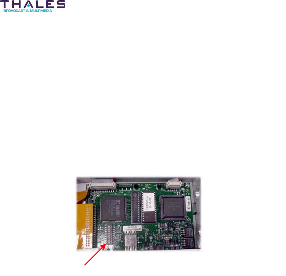
Maintenance and Servicing - 156 -
Affinity® LBD-200C-N1 Transmitter
Product Manual
x If any Power Amplifier Segment and/or plug-in module have a FAIL condition,
contact Thales Customer Service.
Power Amplifier Segment
“Hot Swap” of the Power Amplifier Segment may be required if a failure occurs. To remove a
segment:
x Turn the key-lock switch to the OFF/UNLOCKED position.
x Loosen the thumbscrews on the segment font panel.
x Slide the failed segment out of the Sub-Rack assembly.
Before the replacement segment can be installed, the node address must be set. A set of dual
inline package (DIP) switches located on the microcontroller board of the Power Amplifier
Segment, are used to set the node address (see the following page).
Set the dipswitches of the replacement segment to the same positions as the dipswitches on the
failed segment.
Microcontroller board
Dipswitch
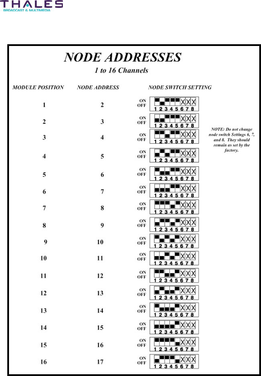
Maintenance and Servicing - 157 -
Affinity® LBD-200C-N1 Transmitter
Product Manual
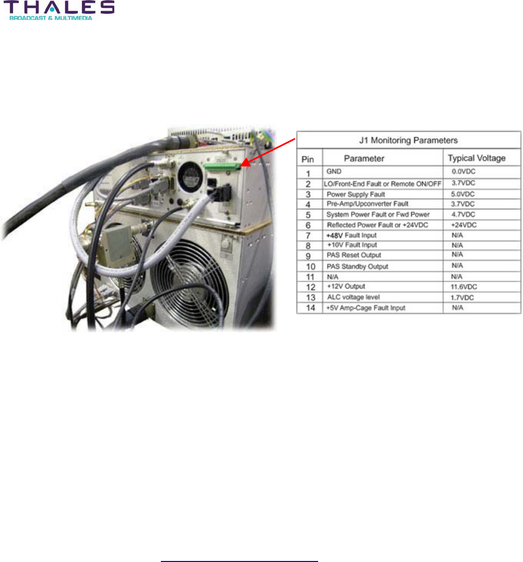
Maintenance and Servicing - 158 -
Affinity® LBD-200C-N1 Transmitter
Product Manual
Troubleshooting Worksheet
The troubleshooting worksheet identifies each interface pin. Fill in the Measured Voltage column
with the values derived from J1.
Sample Worksheet with Typical Voltage Values
Fill in your company information in the space provided on the following page and either mail,
email, or phone in the measured voltage results of the troubleshooting worksheet to the Thales
Customer Service Department:
Thales Broadcast & Multimedia, Inc.
Customer Service Department
104 Feeding Hills Road
Southwick, MA 01077
1-800-345-9295
csfeedback@us.thales-bm.com
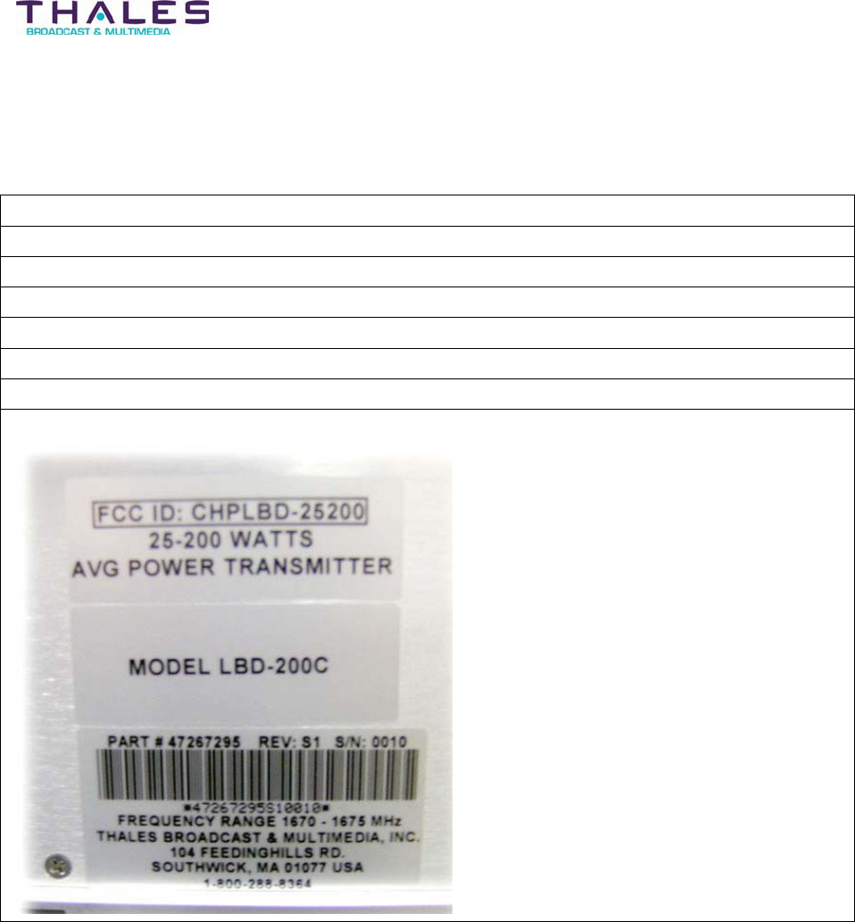
Maintenance and Servicing - 159 -
Affinity® LBD-200C-N1 Transmitter
Product Manual
Attention: Customer Service Department
Company Name
Customer Name
Phone Number
Email Address
Address
Transmitter Model Number
Channel
Serial Number

Status Control and Monitoring System - 160 -
®
Affinity LBD-200C-N1 Transmitter
Product Manual
24 Status Control and Monitoring Systems
This is now Omnitronics SL81
24.1 Parallel Interface
UHF Affinity® Remote Control Interface
Controls Cabinet
Connector/Pin(s)
407755-01
Interconnect Cable
Connector/Pin(s)
Signal Type
RF On/Off J3-1 P3-1 (pair 1 RED) Latched contact closure to
CMD Common (pin 13) for
Off
Power Lower J3-2 P3-2 (pair 1 BLK) Contact closure to CMD
Common (pin 13) to
activate
Power Raise J3-3 P3-3 (pair 2 RED) Contact closure to DMD
Common (pin 13) to
activate
Command Common
(GND)
J3-13 P3-13 (pair 6 BLK) Tied to Gnd inside TX
Status
Transport Stream Input
presence
J3-4 P3-4 (pair 2 BLK) Contact closure between
pins 4&5=Fault
J3-5 P3-5 (pair 3 RED)
Exciter RF Output Fault J3-6 P3-6 (pair 3 BLK) Contact closure between
pins 6&7 =Fault
J3-7 P3-7 (pair 4 RED)
Power Supply Fault J3-8 P3-8 (pair 4 BLK) TTL Low (0V)=Fault
(reference to GND)
Pre-Amp Fault J3-14 P3-14 TTL Low (0V)=Fault
(reference to GND)
Power Amp Fault
(Not currently active)
J3-10 P3-10 (pair 5 RED) TTL Low (0V)=Fault
(reference to GND)
Metering
Forward Power J3-11 (+) P3-11 (+) (pair 5 BLK) 0-4VDC between pins
11&12
J3-12 (-) P3-12 (-) (pair 6 RED)

Block Diagrams and Schematics - 161 -
®
Affinity LBD-200C-N1 Transmitter
Product Manual
25 Block Diagrams and Schematics
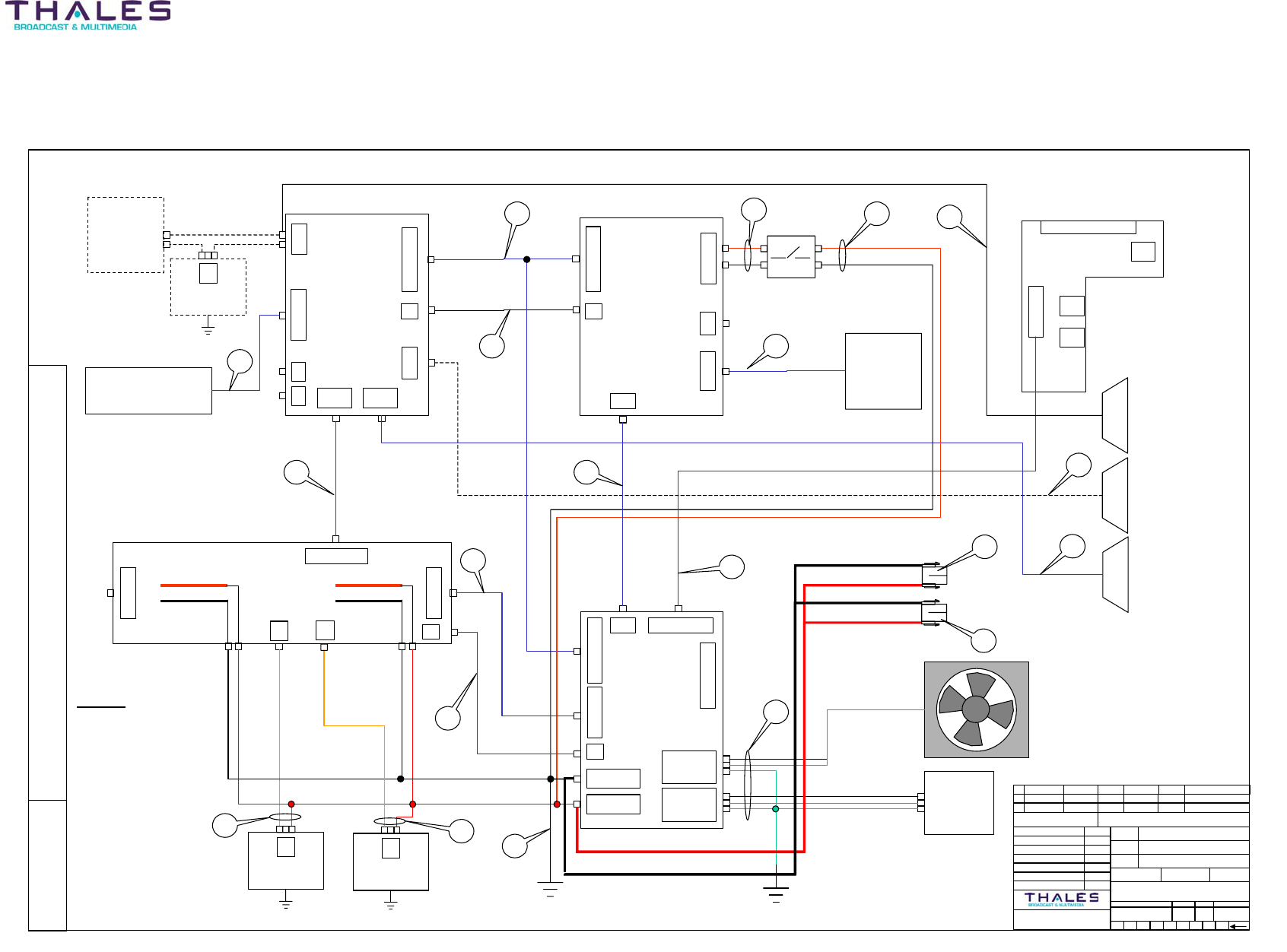
Block Diagrams and Schematics - 162 -
Affinity® LBD-200C-N1 Transmitter
Product Manual
THIS DOCUMENT AND THE INFORMATION IN IT IS THE PROPERTY OF THALES BROADCAST & MULTIMEDIA (THALES) THIS DOCUMENT
AND INFORMATION SHALL NOT BE REPRODUCED OR DICLOSED TO ANY PERSON OR ENTITY WITHOUT PRIOR WRITTEN CONSENT FROM
THALES. CE COCUMENT ET LES INFORMTIONS QU’IL CONTIENT SONT LA PROPIETE DE THALES BROADCAST & MULTIMEDIA ILS NE
PEUVENT ETRE REPRODUITS NI COMMUNIQUES A DES TIERS SANS L’AUTHORISATION PREALABLE ECRITE DE THALES
HANDWRITTEN CHANGE FORBIDDEN
THALES BROADCAST & MULTIMEDIA
© 2005
TITLE:
A ‘ ‘ ‘ ENGINEERING RELEASE06/21/05D.Wike
REV CHANGE ORDER ISSUED DATE DESCRIPTIONDATEAUTHORIZED
UNLESS OTHERWISE
SPECIFIED:
DIMENSIONS ARE IN INCHES. DIMENSIONS IN BRACKETS [X.XX]
ARE IN MILLIMETERS.
ISSUED: 05/11/05
CHECKED: ‘
ENG: 06/20/05
ENG: ‘
PROJECT: ‘
MFG: ‘
EDC: 06/21/05
THALES BROADCAST & MULTIMEDIA
SOUTHWICK, MASSACHUSETTS 01077
MATERIAL SEE PARTS LIST
TREATMENT ‘
FINISH ‘
REV
B
DOCUME NT NUM BE R
47267199 050 B 1 OF 1
DTC CODE SIZE PAGE
PROJECT NO. CAD F ILE SCAL E
NONE47267199-050B.pptRD-DAB-20-TRANS
INTERCONNECT DIAGRAM, 50-200W, L-BAND
TRANSMITTER CHASSIS
D.WIKE
G.DelCampo
‘
‘
‘
‘
D.Tougas
47266066
Rear Panel interface
J1
J5
47266769
MSI PCB
J21
J20
J4
&
J22
J13
J8 J10
J14
J9
33-304-02
RS485 PCB
47267377
envelope detector
J7- Rear Panel 9 Pin D-sub
to modulator command
J4- Rear Panel 15 Pin D-sub
ABCS interface
1
34
5
6
7
750396-01
47266064
Driver Backplane
J15
J5
&
J7
J14
J29
J18
47266165
Power Supply
Backplane
J2
J16 - Load
J17- Neutral
J15 - GND
J1
J4 - Load
J5- Neutral
J3 - GND
47267294
AMP Backplane board
J9
J13
J8
J7BUSS BUSS
J10
J7
AC ENTRY
MODULE
750490-01
J6 & J13 - (+V)
J7 & 14- (-V)
J9
J6 J8
J17
47267088
SNMP DEVICE
SERVER
OPTION KIT
14
11
98
13
10
2
Note:
Ensure jumpers JK1-4 are
configured properly
J2 = Agile Cntrlr Int.
J3 = Local RS485
CABLE KEY
1. 47266293.00-370
2. 754449-01
3. 47266393.00-052
4. 47266392.00-140
5. 47266278.00-180
6. 47266887.00-220
7. 16-086-290
8. 47266294.00-220
9. 47266278.00-050
10. 47266294.00-052
11. 750497-01
12. 47266389 ASSY
13. 47266295.00-100
14. 47266287.00-192
15. 16-021-200
16. 47266385
17. 47267220.00-240
18. 47267370.00-300
19. 47267406.00-070
19
15
A
D
NOTE:
Rear door is grounded using 47266385 ground
strap; Item 16
BLACK
RED
ORANGE
Load = BLACK
Neutral = WHITE
Ground = GREEN
* Use normally closed contacts
J12
+48VDC
+48VDC
+48VDC +48VDC
+10VDC
AC
AC
J2
J2 = 14 Pin Diagnostics Interface
(J1 on Rear Panel)
RJ45 Conn LAN Network Interface
(J5 on Rear Panel)
Two RJ11 Conn RS485
Remote Network Interface
J2
J3
17
12
47267090
12-5V converter
J5
47266389
48-10V converter
J5
17
J14
12
47266389
48-10V converter
J5
-10VDC
Wired as positive ground
Wired as negative ground
ORANGE
18
J6- Rear Panel 9 Pin D-sub
to modulator interface
J8- 48VDC input
J9- 48VDC input
B ‘ ‘ ‘ D.Wike 07/05/05 Add items 18 & 19
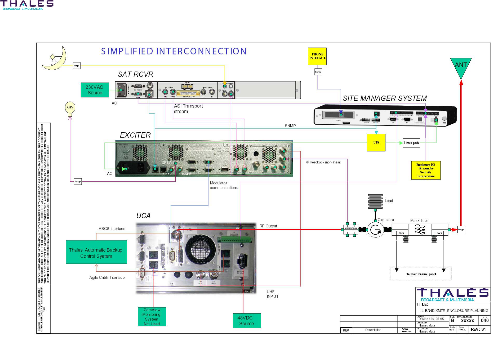
Block Diagrams and Schematics - 163 -
Affinity® LBD-200C-N1 Transmitter
Product Manual

Acronyms and Abbreviations - 164 -
®
Affinity LBD-200C-N1 Transmitter
Product Manual
26 List of Acronyms and Abbreviations
8VSB Trellis Code 8-Level Vestigial Side Band
ABCS Automatic Back-up Controller System
AC Alternating Current
AGC Automatic Gain Control
ALC Automatic Level Control
ASI Asynchronous Serial Interface
BW Bandwidth
CAL Calibrate
CFM Cubic feet per minute
COFDM Coded Orthogonal Frequency Division Multiplexing
CPLD IC Complex Programmable Logic Device
CPLR Coupler
CPR Cardiopulmonary Resuscitation
DAS Direct Analog Synthesizer
dB Decibel
DC Direct Current
DDS Direct Digital Synthesizer
DHCP Dynamic Host Configuration Protocol
DIP Dual-Inline-Package
DPDT Double Pole Double Throw
DTTB Digital Terrestrial Television Broadcasting
DTV Digital Television
DVB-H Digital Video Broadcasting-Handheld
EEPROM Electrically Erasable Programmable Read-Only Memory
EMI Electromagnetic Interference
ETSI European Telecommunications Standards Institute
FCC Federal Communication Commission
FET Field Effect Transistor
FRU Field Replaceable Unit
FTP File Transfer Protocol
Fwd Forward

Acronyms and Abbreviations - 165 -
®
Affinity LBD-200C-N1 Transmitter
Product Manual
GPS Global Positioning Satellite
GUI Graphical User Interface
HVAC Heating, Ventilating and Air-Conditioning
Hz Hertz
I In-Phase
IC Integrated Circuit
IEC International Electrotechnical Commission
IETF Internet Engineering Task Force
IF Intermediate Frequency
IP Internet Protocol
KHz Kilo Hertz
kW Kilo Watt
LAN Local Area Network
LCD Liquid Crystal Display
LDMOS Laterally Diffused Metal Oxide Silicon
LED Light Emitting Diode
LO Local Oscillator
LPF Low Pass Filter
MAN Metropolitan Area Network
MCU Micro Controller Unit
MFN Multi Frequency Networks
MHz Mega Hertz
MIB Management Information Base
MMDS Multi-Channel Multi-Point Distribution System, 2.5-2.7 GHz
MOSFET Metal Oxide Semiconductor Field Effect Transistor
MPEG Moving Pictures Expert Group
MRO Master Reference Oscillator
MSI Master Control Interface
MTTR Mean Time to Repair
MUX Multiplexer
NPN Negative Positive Negative (transistor)
OCXO Oven Controlled Crystal Oscillator
OEM Original Equipment Manufacturer
OID Object Identifier

Acronyms and Abbreviations - 166 -
®
Affinity LBD-200C-N1 Transmitter
Product Manual
OS Operating System
PA Power Amplifier
PAS Power Amplifier Segment
PC Personal Computer
PCB Printed Circuit Board
PIN Positive Intrinsic Negative
PIOS Peripheral Input/Output System
PLL Phase Lock Loop
PLO Phase Locked Oscillator
PNP Positive Negative Positive (transistor)
PSTN Public Switched Telephone Network
Pwr Power
Q Quadrature
QAM Quadrature Amplitude Modulation
RAM Random Access Memory
RF Radio Frequency
RMS Root Mean Square
RU Rack Unit
RX Receive
SFN Single Frequency Networks
SMA Sub-Miniature-A
SMCS Status Monitor and Control System
SMM Site Management Module
SNMP Simple Network Management Protocol
SPI Serial Peripheral Interface
SSB Single Side Band
SYS System
TB Terminal Barrier Strip
TCP/IP Transmission Control Protocol/Internet Protocol
Temp Temperature
TFTP Trivial File Transfer Protocol
TTL Transistor-Transistor-Logic
Tx Transmitter
TX Transmit

Acronyms and Abbreviations - 167 -
®
Affinity LBD-200C-N1 Transmitter
Product Manual
UBS Unique Broadband Systems, Inc.
UCA Upconverter Amplifier
UHF Ultra High Frequency
VAC Voltage Alternating Current
VCO Voltage Controlled Oscillator
VDC Voltage Direct Current
VHF Very High Frequency
VSWR Voltage Standing Wave Ratio
V-Tune Voltage Control
WWatt
WAN Wide Area Network
WLL Wireless Local Loop, 3.4-3.6 GHz

Warranty - 168 -
®
Affinity LBD-200C-N1 Transmitter
Product Manual
27 Warranty
Thales Broadcast & Multimedia Inc. warrants each product of its manufacture to be free from
any defect in material and workmanship for a period of one year after delivery to, and return by,
the original purchaser. No returns, however, will be accepted unless accompanied by a written
factory return authorization.
The limit of liability under this warranty shall be to repair or replace any product, or part thereof,
which proves to be defective after inspection by Thales Broadcast & Multimedia, Inc. With the
exception of lamps, fuses or any equipment manufactured by others, which are subject to only
such loss adjustments as Thales Broadcast & Multimedia, Inc. may obtain from the suppliers
thereof.
This warranty shall not apply to any Thales Broadcast & Multimedia, Inc. product, which has
been modified physically or electrically damaged, or to modules which seals have been broken,
or any product, which has been subjected to conditions exceeding the applicable specifications
or ratings or improper service techniques.
Thales Broadcast & Multimedia, Inc. reserves the right to make design changes to any Thales
Broadcast & Multimedia, Inc. product without incurring any obligation to make the same
changes to previously purchased units.
This warranty is the full extent of the obligation and liability assumed by Thales Broadcast &
Multimedia, Inc. with respect to any and all Thales Broadcast & Multimedia, Inc. products.
Thales Broadcast & Multimedia, Inc. neither makes, nor authorizes any person to make, any
other guarantee or warranty concerning Thales Broadcast & Multimedia, Inc. products.

Parts Lists - 169 -
®
Affinity LBD-200C-N1 Transmitter
Product Manual
28 Parts Lists

Appendix - 170 -
Affinity® LBD-200C-N1 Transmitter
Product Manual
29 Appendix
29.1 Section A- Hazardous Materials List
29.2 Section B- Site Drawings
29.3 Section C- List of Modules and Site ID, with Barcode Number
29.4 Section D- Site Acceptance Document
29.5 Section E- Log File

Thales Broadcast & Multimedia, Inc.
104 Feeding Hills Road
Southwick MA 01077-USA
Tel: (413) 998-1100
1-800-345-9295
www.thales-bm.com
Made and printed in the U.S.A.