Thomson Broadcast and Multimedia LBD-25200 Affinity L-Band Transmitter for Mobile Media Svs. User Manual Affinity LBD 200C N1 DRAFT1
Thomson Broadcast & Multimedia, Inc. Affinity L-Band Transmitter for Mobile Media Svs. Affinity LBD 200C N1 DRAFT1
Contents
- 1. Software Users Guide
- 2. 200W User Manual part 1
- 3. 200W User Manual part 2
- 4. 200W User Manual part 3
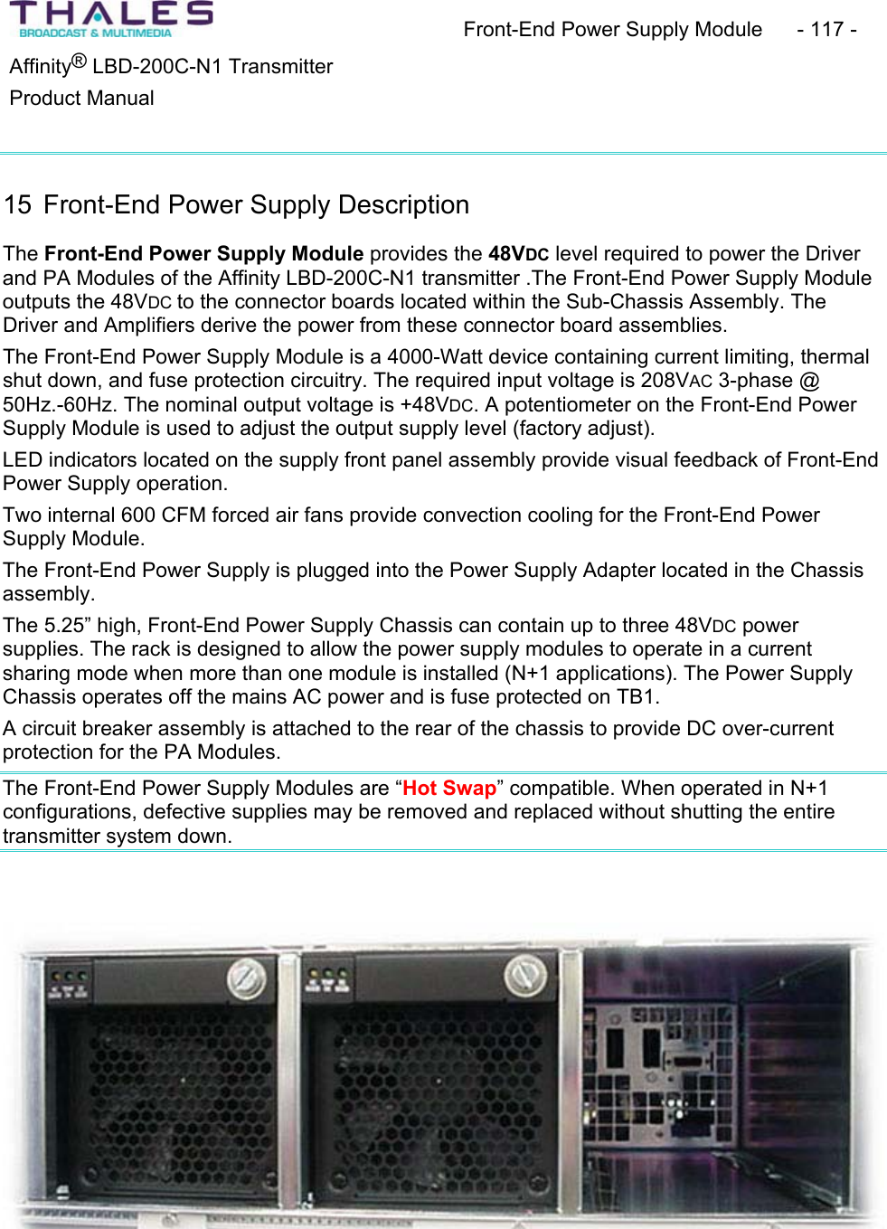
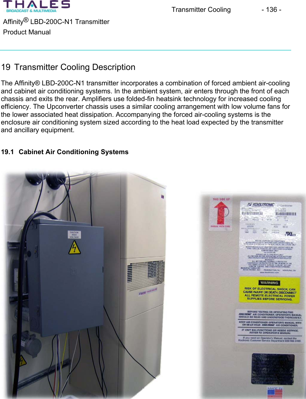
200W User Manual part 3
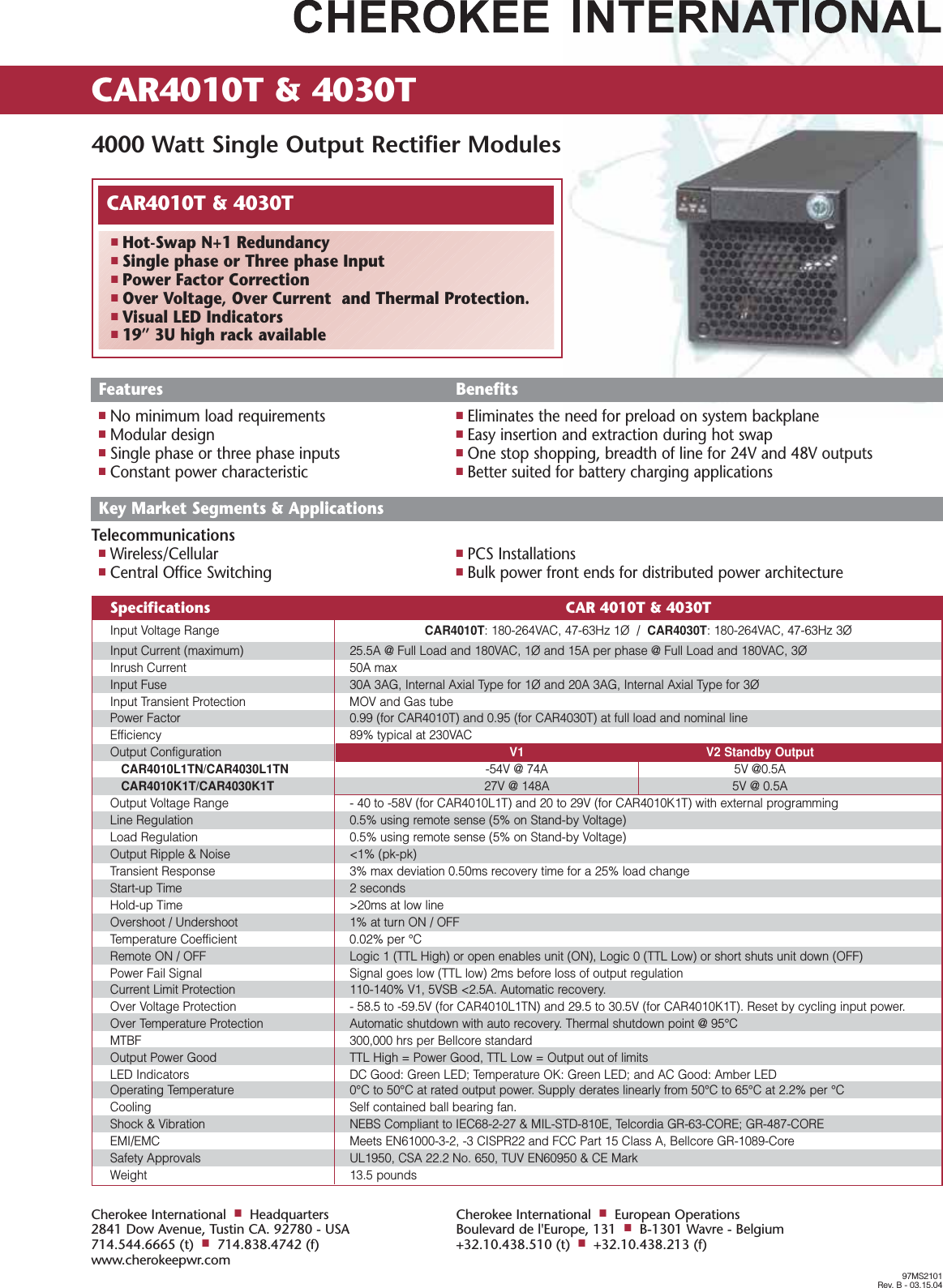
![K2A3C18RP55R R22 Recognized 18000 125 0 51.7 -17.8 230 60 21.6 5.3/8.8K2A3C20RP55R R22 Recognized 20000 125 0 51.7 -17.8 230 60 21.6 5.3/8.8K2A3C22RP55R R22 Recognized 22000 125 0 51.7 -17.8 230 60 21.6 5.3/8.8UL/CUL Ambient Temp. ***Listed or BTU/H °F °C Cooling HeatingModel Refrigerant Recognized Rating Max. Min. Max. Min. Volts Hz Amps AmpsTECHNICAL DATA* Rating shown is for operation at maximum ambient temperature.** Optional Single Enclosure Heater/Double Enclosure HeaterADVANTAGE RP55 SERIES AIR-COOLEDPANEL-MOUNTED AIR CONDITIONERSACCESSORIES AND OPTIONS*QCooling Effect DetectorQEnclosure HeaterQFilter Recoating AdhesiveQFilters for replacementQInternal corrosion protectionQPower Loss Delayed Compressor StartQSpecial paint finishes*See opposite side for more information.POPULAR MODELS ARESTOCKED AND READY TO SHIPHOW TO ORDERSpecify model number. NOTE: Accessoriesand Options may affect model number,contact KOOLTRONIC for information.For assistance in model selection, refer tothe Air Conditioner Sizing and SelectionGuide, contact KOOLTRONIC, or useone of our design aid software programs,available FREE.CALL 1-800-321-KOOL (5665)or FAX 609-466-1114APPROXIMATE WEIGHT298 lbs. [135.5 kg]STANDARD FEATURESTextured Baked Powder FinishBuilt-in Condensate EvaporatorLow ODP RefrigerantClosed-Loop CoolingCrankcase Compressor HeaterDigital Temperature DisplayEMI/RFI SuppressorHead Pressure Control SwitchHeavy-duty Steel EnclosureLow Ambient KitLow Temperature Control ThermostatM/TAB Mounting SystemNEMA3R Rating Maintained (UL50)Permanent FiltersSix Foot [1.8m] (minimum) SJT 3-wire CordUL/CUL RecognizedKooltronic, Inc., 30 Pennington-Hopewell Road, P.O. Box 240, Pennington, NJ 08534-0240Tel: (609) 466-3400 Fax: (609) 466-1114 Internet: www.kooltronic.com E-Mail: sales@kooltronic.comMOUNTING PLAN 55.62[1412.7mm]21.99[558.6mm]17.34[440.4mm]56.20[1427.5mm]FILTERED CONDENSERAIR INLET (Ambient Air In)CONDENSER OUTLET(Warm Ambient Air Out)WARM AIR RETURNFROM ENCLOSURECOOL AIR OUTLETTO ENCLOSURE❶❸❷❹❶❷❹❸❹❸Dimensions, inches [metric], are for reference only and are subject to change.19.25[489.0mm]2.43[61.7mm]10.00[254.0mm]31.44[489.0mm]2.34[59.4mm]10.00[254.0mm]1.99[50.5mm]18.00[457.2mm]7.31[185.7mm]2.68[68.1mm]1.37[34.8mm](16) .281 [7.0mm]DIA. HOLES21.99[558.6mm]56.20[1427.5mm]UNIT MUST BE 4" MINIMUMABOVE FLOOR FOR FILTERACCESSrp55.qxd8/23/05K2A3C20RP55R](https://usermanual.wiki/Thomson-Broadcast-and-Multimedia/LBD-25200.200W-User-Manual-part-3/User-Guide-589669-Page-23.png)
![DESCRIPTIONAt last - air conditioners designed specifically for cooling electronic enclosures that can be used for both indoor and outdoor applications right out of thebox!No more bulky unattractive weather hoods... No more worries over what options to specify for outdoor applications.Expertly designed and crafted, the ADVANTAGE Series boasts a stylish appearance with rounded edges, no visible hardware and a textured bakedpowder finish to blend easily with contemporary enclosure designs.Servicability has been made easier by incorporating a “knock-down” sheetmetal design which provides quick access to internal components.Standard features include heavy duty galvanized steel construction with baked-on powder paint, environmentally friendly refrigerants, built-incondensate evaporator, thermostatic low temperature control and EMI/RFI Suppressor. These air conditioners are available in capacities from1,000 to 22,000 BTU/H in seven heights, all utilizing the exclusive KOOLTRONIC M/TAB integral mounting system.KOOLTRONIC also designs and manufactures a variety of Air Conditioners to meet unique specifications. We invite your inquiries about ourmodification and custom-design capabilities.STANDARD FEATURESCLOSED-LOOP COOLING: The enclosure interior airflow system is isolated from the ambient airflow system. Ambient air can not invade the cool,dehumidified sensitive component compartment. BALL-BEARING MOTORS: All fan motors are UL/CSA Recognized and include automatic-reset thermal overload protection and double-sealed ordouble-shielded precision ball bearings. Special permanent lubricants in the tube axial fans perform over a broad temperature range: -20°F [-28.9°C] to250°F [121.1°C].RUGGED CONSTRUCTION: Precision-engineered heavy gauge steel construction of all cabinets and blowers insures Air Conditioners will stand upunder tough applications.TEXTURED BAKED POWDER FINISH: Durable, baked-on textured beige powder finish is standard. Other finishes are available.POWER: Available in 230 VAC, 50 Hz or 60 Hz. REFRIGERANT: Low Ozone Depleting Potential (ODP) R22 Refrigerant is used in all Advantage RP55 Series Air Conditioners and are being con-verted to CFC-free R134a Refrigerant as compressors become available. Consult KOOLTRONIC for status at time of requirement. PERMANENT FILTERS: Multi-layer grid of sturdy, corrugated aluminum in an aluminum frame. May be reused after washing off accumulations andspraying with A-16 Recoating Adhesive.CONDENSATE EVAPORATOR: Built-in Condensate Evaporator eliminates need for draining condensate under normal operating conditions. Maynot be adequate in extremely high humidity with open or leaky enclosure. Overflow condensate drain fitting and hose are included.LOW AMBIENT KIT: Maintains sufficient operating pressures when ambient temperatures drop below 50°F [10°C]. Includes a compressor heater andpressure actuated condenser blower cycling control.LOW TEMPERATURE CONTROL: Thermostatic Low Temperature Control prevents over-cooling and provides energy-efficient operation. EMI/RFI SUPPRESSOR: EMI/RFI Suppressor minimizes transient line spikes during on/off cycling.CRANKCASE COMPRESSOR HEATER: 240V heater attached to the compressor crankcase to maintain appropriate temperatures during coldoperating conditions.HEAD PRESSURE CONTROL SWITCH: A control device to minimize compressor cycling and prevent evaporator coil icing.POWER CORD: All models have six foot [1.8m] SJT-type 3-wire power cords with appropriate plugs.INSULATION: All cold components, lines and the evaporator compartment are insulated with high-performance insulation for maximum efficiency.GASKETING: All units are fully gasketed for tight, leakproof installation, in compliance with the NEMA 3R Enclosure Rating.QUALITY ASSURANCE: Refrigeration system components are kept sealed until charged with refrigerant; all brazed joints are thoroughly leak-tested;each unit is functionally tested before shipment. INSTALLATION: Detailed Installation and Operator's Manual, with drawings, mounting plan and spare parts list is included with each unit.UL/CUL RECOGNIZED: All Advantage RP55 models are UL/CUL Recognized. All Recognized models are available as Listed at added cost.ACCESSORIES AND OPTIONS**FACTORY-INSTALLED OPTIONS:COOLING EFFECT DETECTOR: A thermostat is mounted inside the cabinet and attached to a sensor in the warm air return. When the airtemperature increases to the set point, a signal is sent to a terminal block. User-installed wiring from the terminal block to local and/or remote warningdevices (light, bell, siren, etc.) can be for normally open or closed operation.Append letter "B" to Part No.ENCLOSURE HEATER: 240V fin strip heater, installed singly or ganged, used to maintain desired internal enclosure temperature, under cold oper-ating conditions.Single Heater, append letter "F" to Part No.Double Heater, append letter “G” to Part No.**Contact KOOLTRONIC for information.](https://usermanual.wiki/Thomson-Broadcast-and-Multimedia/LBD-25200.200W-User-Manual-part-3/User-Guide-589669-Page-24.png)
![ACCESSORIES AND OPTIONS** (continued)INTERNAL CORROSION PROTECTION: For corrosive or other hostile environments, special coating material is applied to copper lines, coilsand other parts subject to damage.Append letter "H" to Part No.POWER LOSS DELAYED COMPRESSOR START: Protects the compressor from possible damage due to harmful short cycling, by initiating an“off” period before resumption of normal operation. Generally air conditioners require several minutes off for compressor protection after power inter-ruptions of any type. These power interruptions can include power failures, opening of interlocked access doors, and cases where a thermostat activatesthe compressor in less than a few minutes. This option is particularly recommended for applications where frequent, brief power failures occur, inter-locked cabinet doors are utilized, or where the cabinet internal loads fluctuate across a wide range.Append letter "Y" to Part No.SHORT CYCLE PROTECTOR: Protects the compressor from possible damage due to harmful short cycling, by initiating an "off" period beforeresumption of normal operation. Generally air conditioners require several minutes off for compressor protection after power interruptions of any type.These power interruptions can include power failures, opening of interlocked access doors, and cases where a thermostat activates the compressor inless than a few minutes. This option is particularly recommended for applications where frequent, brief power failures occur, interlocked cabinet doorsare utilized, or where the cabinet internal loads fluctuate across a wide range.Append letter "Y" to Part No.SPECIAL PAINT FINISHES**PAINTED METAL GRILLE** Append letter “Z” to Part No.CUSTOMER-INSTALLED OPTIONS:FILTERS FOR REPLACEMENT: All KOOLTRONIC filters consist of a multi-layer grid of sturdy corrugated aluminum, securely held in a one-piecealuminum frame. Filters are required wherever air is drawn into an electronics enclosure or related cooling equipment to keep internal parts as clean as possible. A non-drying adhesive coating traps a high percentage of particulate matter. These washable, reusable filters are designed to last the life of the coolingunit. Replacements are available for those which become damaged or otherwise non-serviceable.Part No. 11631F (11.63 x 21.63 x 0.38 [295mm x 321mm x 10mm])FILTER RECOATING ADHESIVE: This compound is a superior product for recoating all permanent filters after washing. The adhesives penetratedirt layers to keep the filter surface tacky for longer effective performance between washings. Part No. A-16 - one pint container.**Contact KOOLTRONIC for information. Kooltronic, Inc., 30 Pennington-Hopewell Road, P.O. Box 240, Pennington, NJ 08534-0240Tel: (609) 466-3400 Fax: (609) 466-1114 Internet: www.kooltronic.com E-Mail: sales@kooltronic.com](https://usermanual.wiki/Thomson-Broadcast-and-Multimedia/LBD-25200.200W-User-Manual-part-3/User-Guide-589669-Page-25.png)

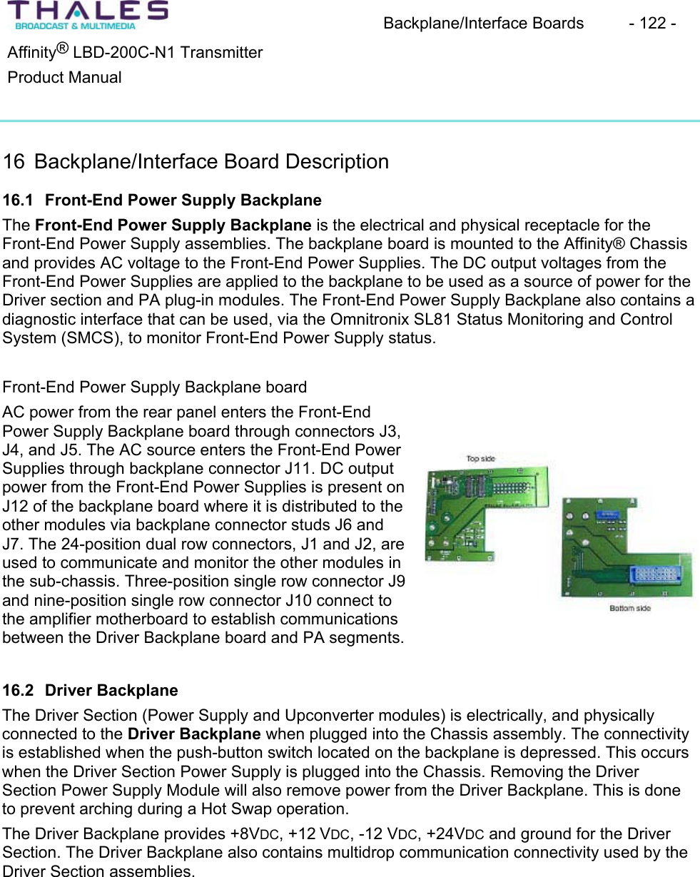
![Setup & Detailed Alignment Procedures - 147 - Affinity® LBD-200C-N1 TransmitterProduct Manual2. In order to calibrate the reflected meter, swap the forward sample and reflected samplecables on detector module.3. Set NORMAL DEBUG MODE = 1(For a complete explanation of debug modes see DOC#25-0021). The screen will auto refresh. Note, that the variable names no longerrepresent actual parameter. DOC# 25-0021 explains the function of each parameterunder the various debug modes. (Normal debug mode = 1 is used for meter calibration.)4. Under the monitored variables frame, read values displayed in the third row. The value in the cell titled LOW is first multiplied by 256 then added to the value in the cell titled HIGH. The resulting value from this operation is now entered into SYSTEM REFLECTED POWER REFERENCE parameter. This completes the reflect metercalibration.5. Return the cables to normal position.6. Set HEALTH SNAPSHOT 65535 to clear any faults. 22.6 Calibrate Fast Reflected Shut Down1. Sample the Transmitter output using an inline variable attenuator. Set the level to -5dBmand connect this signal to the reflected port of TRU RMS detector module.2. Raise level slowly until the preamplifier LCD display of reflected power reads 15%. 3. Lower the FAST REFLECTED THRESHOLD until the power is reduced by approx. 6dB(this power reduction is pre determined) A typical value of fast reflected threshold = 1000. This threshold must be precise. Use smaller calibrations steps when reaching near the value of 1000. 4. Once tripped, it will stay at reduced power. To verify or to recalibrate, lower the sampleand reset the module; use the reset button on the EMSET window for this purpose.5. Verify that you can raise the reflected power percentage to at least 10% without the transmitter tripping into the 6dB protection mode. Also, exceed the 15% mark to activate the protection system. Again, reset the module back into normal operation when this testis completed.6. Set system reflected power percent limit to = 25. 7. Return all cables to normal position.8. Set HEALTH SNAPSHOT 65535 to clear any faults. 22.7 Non-linear Precorrection1. Navigate to the menu for non-linear calibration on the exciter front panel; this is locatedunder the F5 button on the keypad located below the display window [Press F5 once]. The feedback sample should be connected prior to the channel filter (default location). 2. Observe that the feedback level is Normal; see feedback level indicator (typical level is –15dBm).3. Apply a one-shot or place the correction in adaptive mode; allow a few seconds for automatic correction. 4. Observe the shoulder level; ensure it is within tolerable limits (i.e. t34dB).](https://usermanual.wiki/Thomson-Broadcast-and-Multimedia/LBD-25200.200W-User-Manual-part-3/User-Guide-589669-Page-33.png)
![Setup & Detailed Alignment Procedures - 148 - Affinity® LBD-200C-N1 TransmitterProduct Manual22.8 Linear Precorrection1. Navigate to the menu for linear calibration on the front panel of the exciter; this is locatedunder the F5 button on the keypad located below the display window [Press F5 twice]. The feedback sample should be connected after the channel filter.2. Observe that the feedback level is Normal; see feedback level indicator.3. Apply a one-shot or place the correction in adaptive mode; allow a few seconds for automatic correction. 4. Observe the frequency response and group delay; ensure they are within tolerable limits.22.9 Raise & Lower Power1. Navigate to the menu for POWER & CONTROL on the exciter front panel; this is locatedunder the F3 button on the keypad located below the display window [Press F3 once].2. Change power by selecting the appropriate output power in a percentage value. An increase or decrease can be achieved, so long as the maximum rating of the transmitteris not exceeded. (Example: to reduce the transmitter to 90% output, select 90% in menucontrol.)3. Observe the power adjustment.NOTE: To succeed in performing this step requires prior transmitter meter calibration or original default factory calibration settings.](https://usermanual.wiki/Thomson-Broadcast-and-Multimedia/LBD-25200.200W-User-Manual-part-3/User-Guide-589669-Page-34.png)

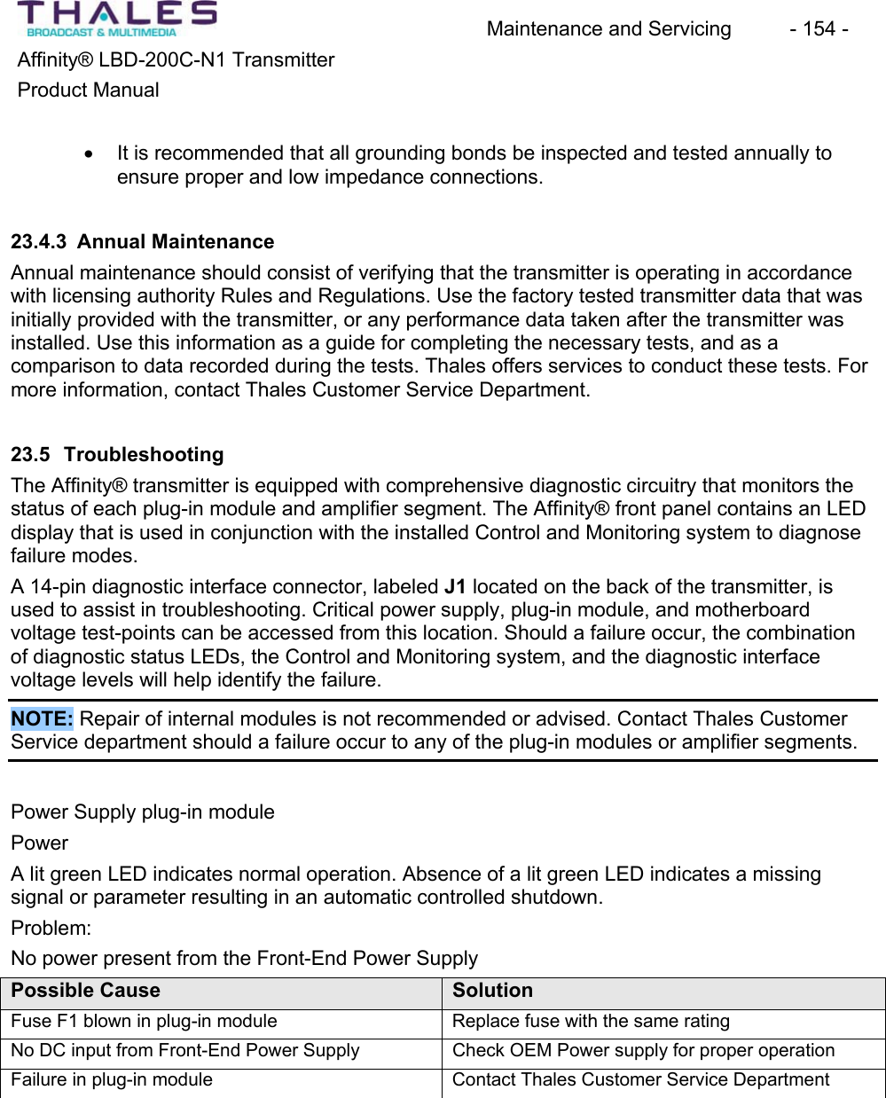


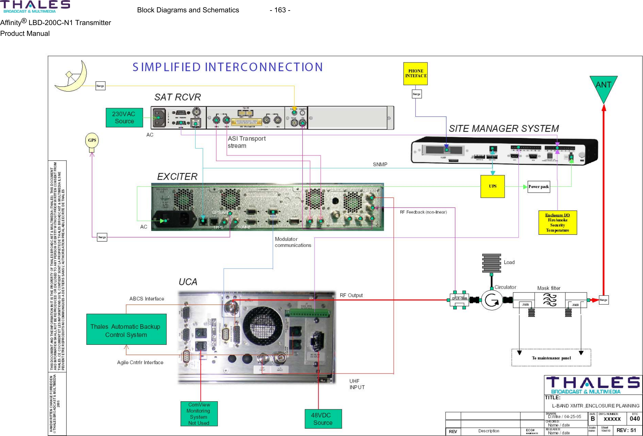
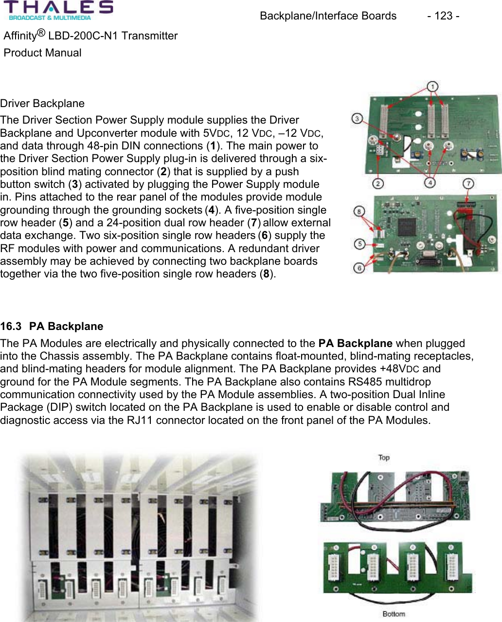
![Block Diagrams and Schematics - 162 - Affinity® LBD-200C-N1 Transmitter Product Manual THIS DOCUMENT AND THE INFORMATION IN IT IS THE PROPERTY OF THALES BROADCAST & MULTIMEDIA (THALES) THIS DOCUMENTAND INFORMATION SHALL NOT BE REPRODUCED OR DICLOSED TO ANY PERSON OR ENTITY WITHOUT PRIOR WRITTEN CONSENT FROM THALES. CE COCUMENT ET LES INFORMTIONS QU’IL CONTIENT SONT LA PROPIETE DE THALES BROADCAST & MULTIMEDIA ILS NE PEUVENT ETRE REPRODUITS NI COMMUNIQUES A DES TIERS SANS L’AUTHORISATION PREALABLE ECRITE DE THALESHANDWRITTEN CHANGE FORBIDDENTHALES BROADCAST & MULTIMEDIA© 2005TITLE:A ‘ ‘ ‘ ENGINEERING RELEASE06/21/05D.WikeREV CHANGE ORDER ISSUED DATE DESCRIPTIONDATEAUTHORIZEDUNLESS OTHERWISE SPECIFIED:DIMENSIONS ARE IN INCHES. DIMENSIONS IN BRACKETS [X.XX] ARE IN MILLIMETERS.ISSUED: 05/11/05CHECKED: ‘ENG: 06/20/05ENG: ‘PROJECT: ‘MFG: ‘EDC: 06/21/05THALES BROADCAST & MULTIMEDIASOUTHWICK, MASSACHUSETTS 01077MATERIAL SEE PARTS LISTTREATMENT ‘FINISH ‘REVBDOCUME NT NUM BE R47267199 050 B 1 OF 1DTC CODE SIZE PAGEPROJECT NO. CAD F ILE SCAL ENONE47267199-050B.pptRD-DAB-20-TRANSINTERCONNECT DIAGRAM, 50-200W, L-BANDTRANSMITTER CHASSISD.WIKEG.DelCampo‘‘‘‘D.Tougas47266066Rear Panel interfaceJ1J547266769MSI PCBJ21J20J4&J22J13J8 J10J14J933-304-02RS485 PCB47267377envelope detectorJ7- Rear Panel 9 Pin D-subto modulator commandJ4- Rear Panel 15 Pin D-subABCS interface134567750396-0147266064Driver BackplaneJ15J5&J7J14J29J1847266165Power Supply BackplaneJ2J16 - LoadJ17- NeutralJ15 - GNDJ1J4 - LoadJ5- NeutralJ3 - GND47267294AMP Backplane boardJ9J13J8J7BUSS BUSSJ10J7AC ENTRYMODULE750490-01J6 & J13 - (+V)J7 & 14- (-V)J9J6 J8J1747267088SNMP DEVICESERVEROPTION KIT14119813102Note:Ensure jumpers JK1-4 are configured properly J2 = Agile Cntrlr Int.J3 = Local RS485CABLE KEY1. 47266293.00-3702. 754449-013. 47266393.00-0524. 47266392.00-1405. 47266278.00-1806. 47266887.00-2207. 16-086-2908. 47266294.00-2209. 47266278.00-05010. 47266294.00-05211. 750497-0112. 47266389 ASSY13. 47266295.00-10014. 47266287.00-19215. 16-021-20016. 4726638517. 47267220.00-24018. 47267370.00-30019. 47267406.00-0701915ADNOTE:Rear door is grounded using 47266385 ground strap; Item 16BLACKREDORANGELoad = BLACKNeutral = WHITEGround = GREEN* Use normally closed contactsJ12+48VDC+48VDC+48VDC +48VDC+10VDCACACJ2J2 = 14 Pin Diagnostics Interface (J1 on Rear Panel)RJ45 Conn LAN Network Interface (J5 on Rear Panel)Two RJ11 Conn RS485 Remote Network Interface J2J317124726709012-5V converterJ54726638948-10V converterJ517J14124726638948-10V converterJ5-10VDCWired as positive groundWired as negative groundORANGE18J6- Rear Panel 9 Pin D-subto modulator interfaceJ8- 48VDC inputJ9- 48VDC inputB ‘ ‘ ‘ D.Wike 07/05/05 Add items 18 & 19](https://usermanual.wiki/Thomson-Broadcast-and-Multimedia/LBD-25200.200W-User-Manual-part-3/User-Guide-589669-Page-48.png)