Thrane and Thrane A S 6300B Sailor 6366 TU MF/HF 150W DSC Class A FCC User Manual
Thrane & Thrane A/S Sailor 6366 TU MF/HF 150W DSC Class A FCC
UserManual.wiki
>
Thrane and Thrane A S
>
6300B User Manual
>
User manual
Contents
1.
User manual
2.
Installation guide
3.
Installation manual
4.
Service interface manual
User manual
Navigation menu
Upload a User Manual
Namespaces
Wiki Guide
HTML
PDF
Info
Views
User Manual
Discussion / Help
Navigation
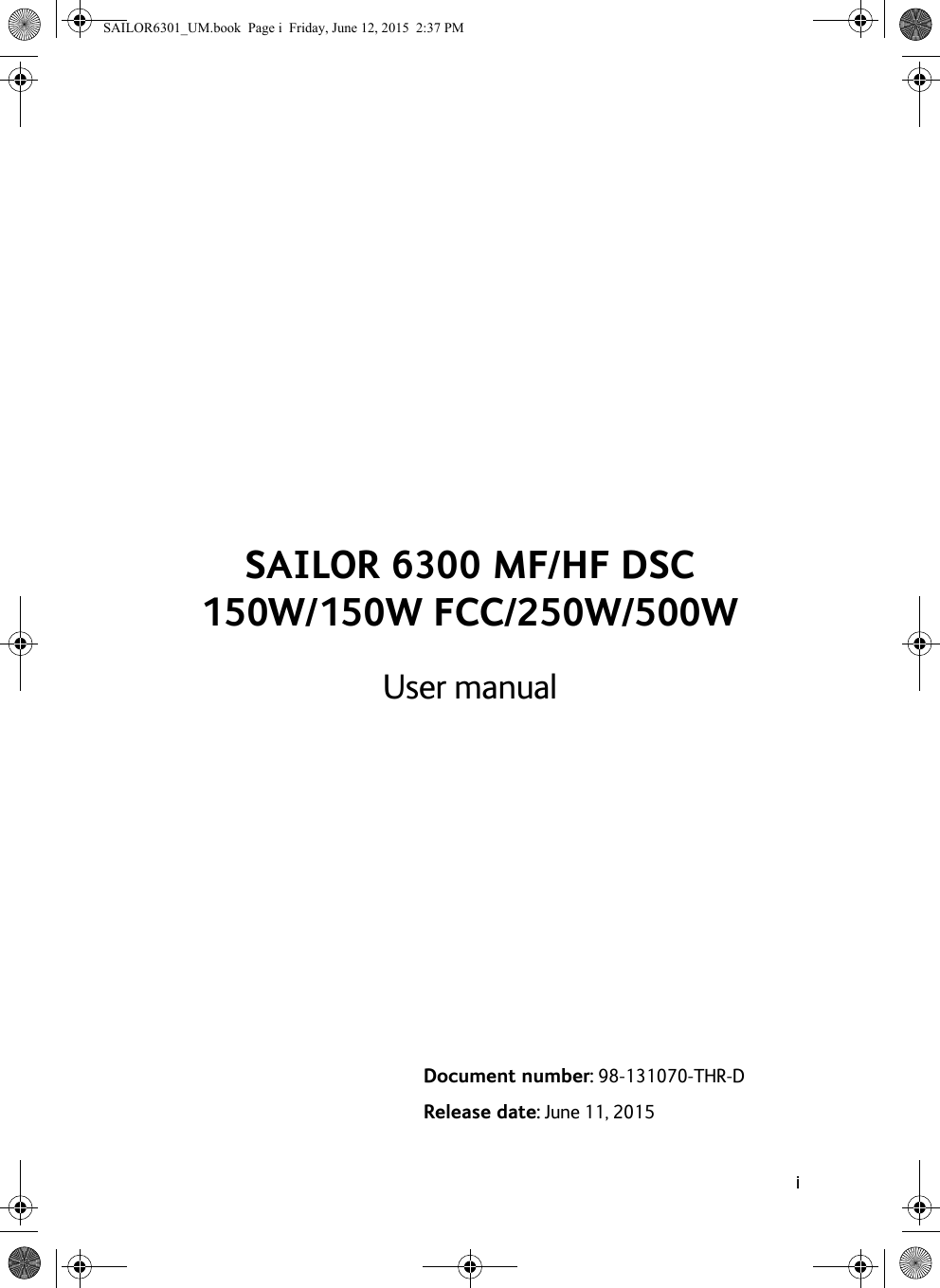
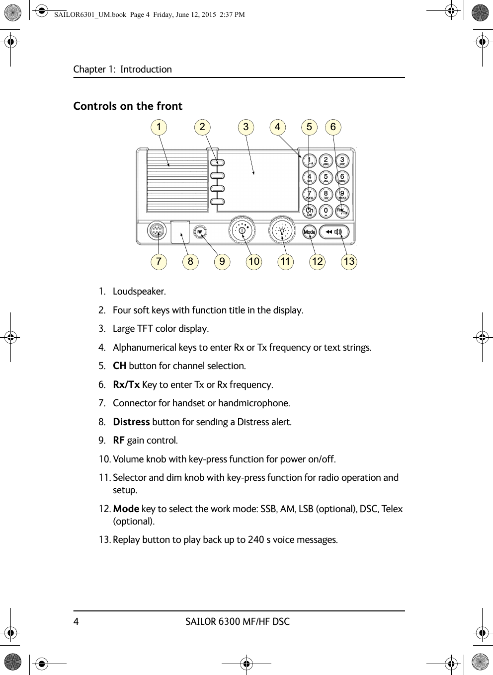
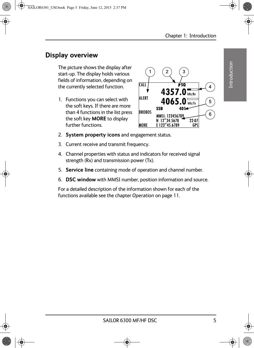


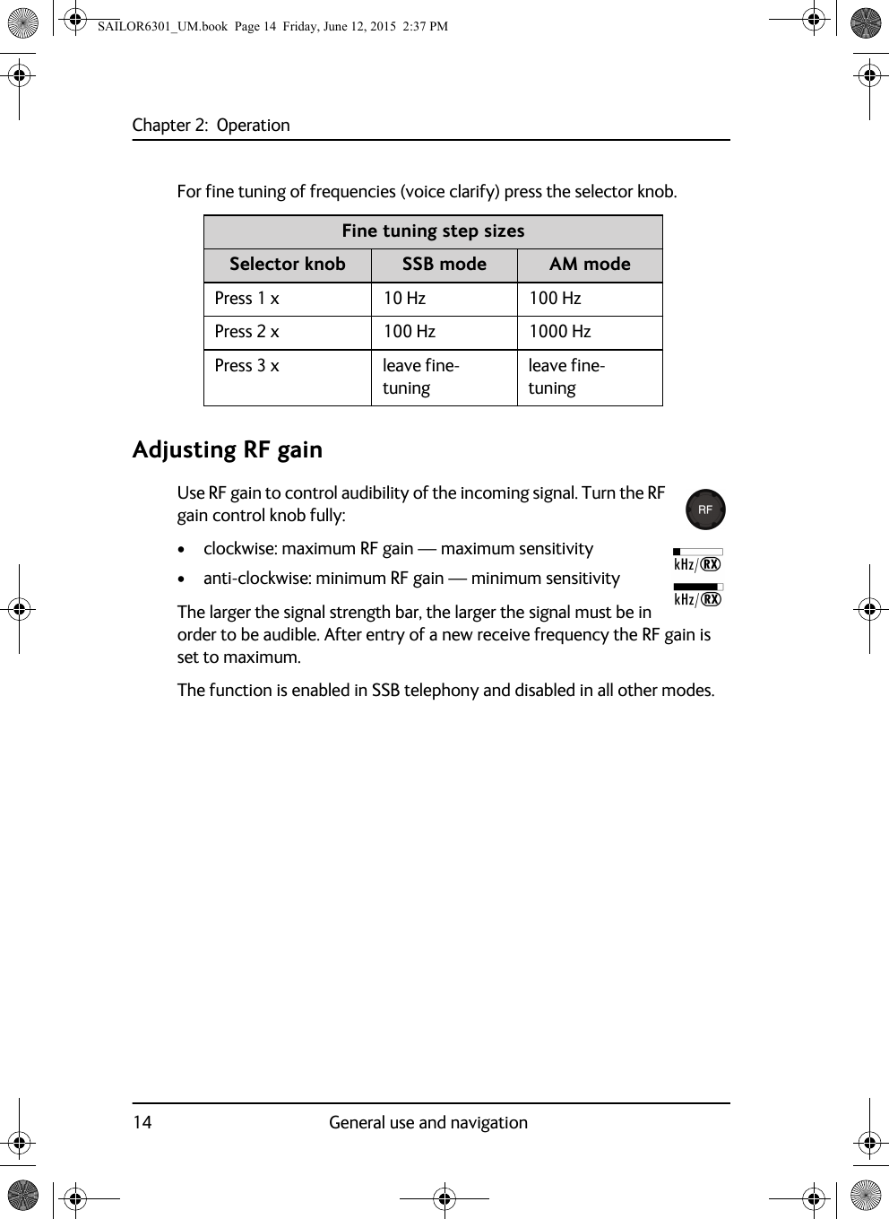
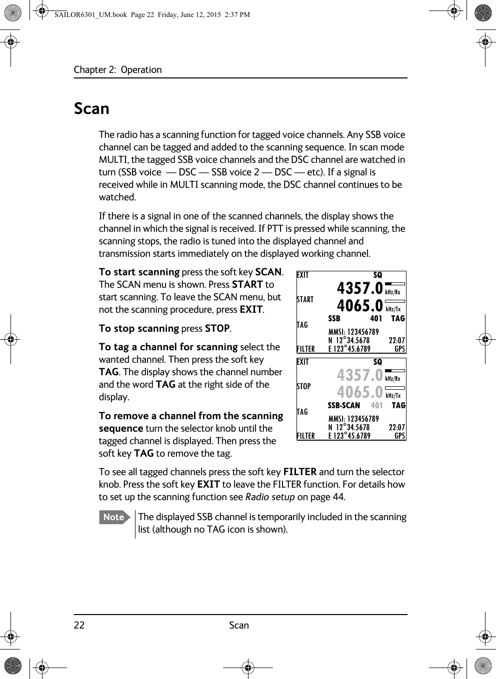
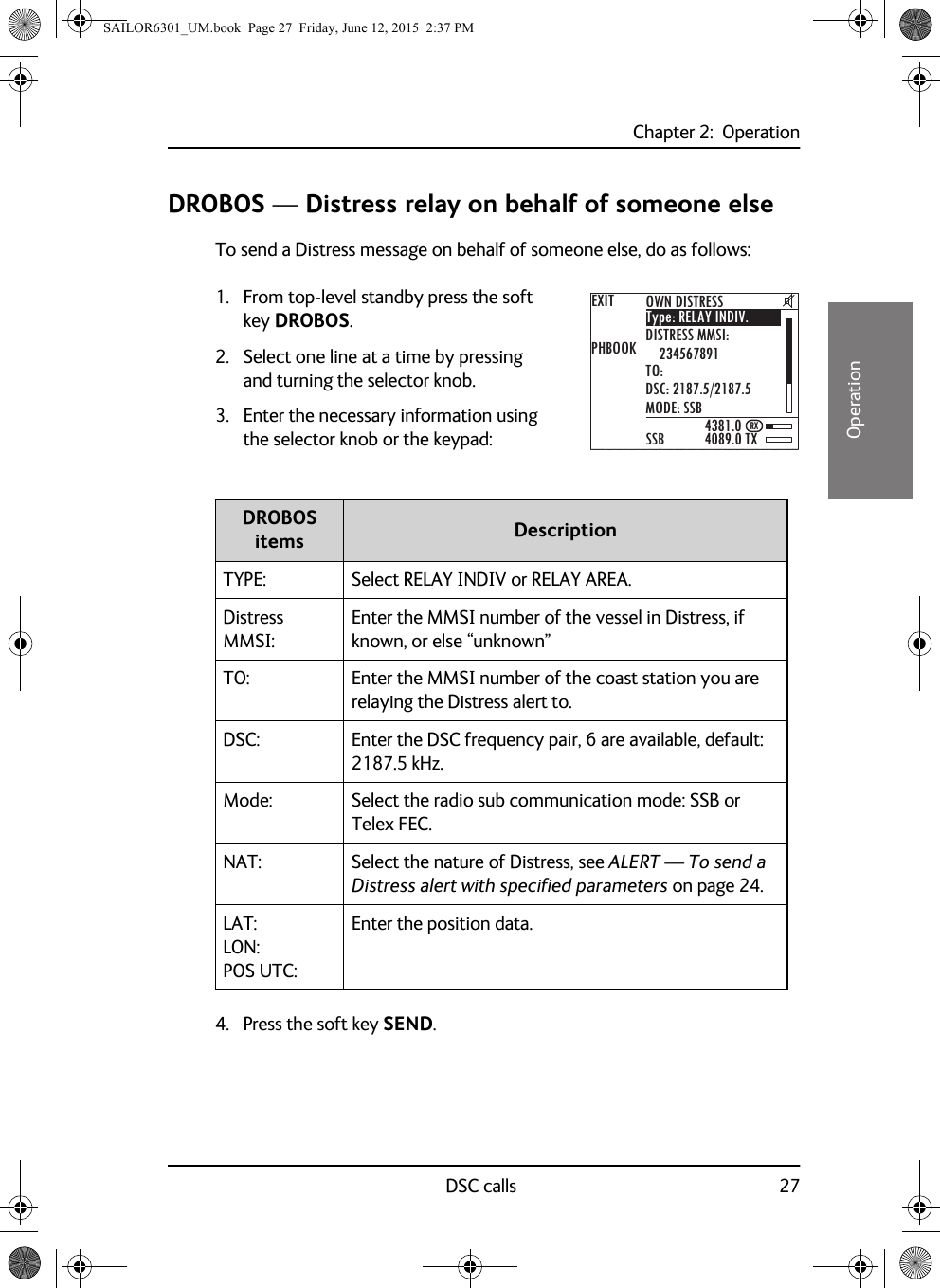
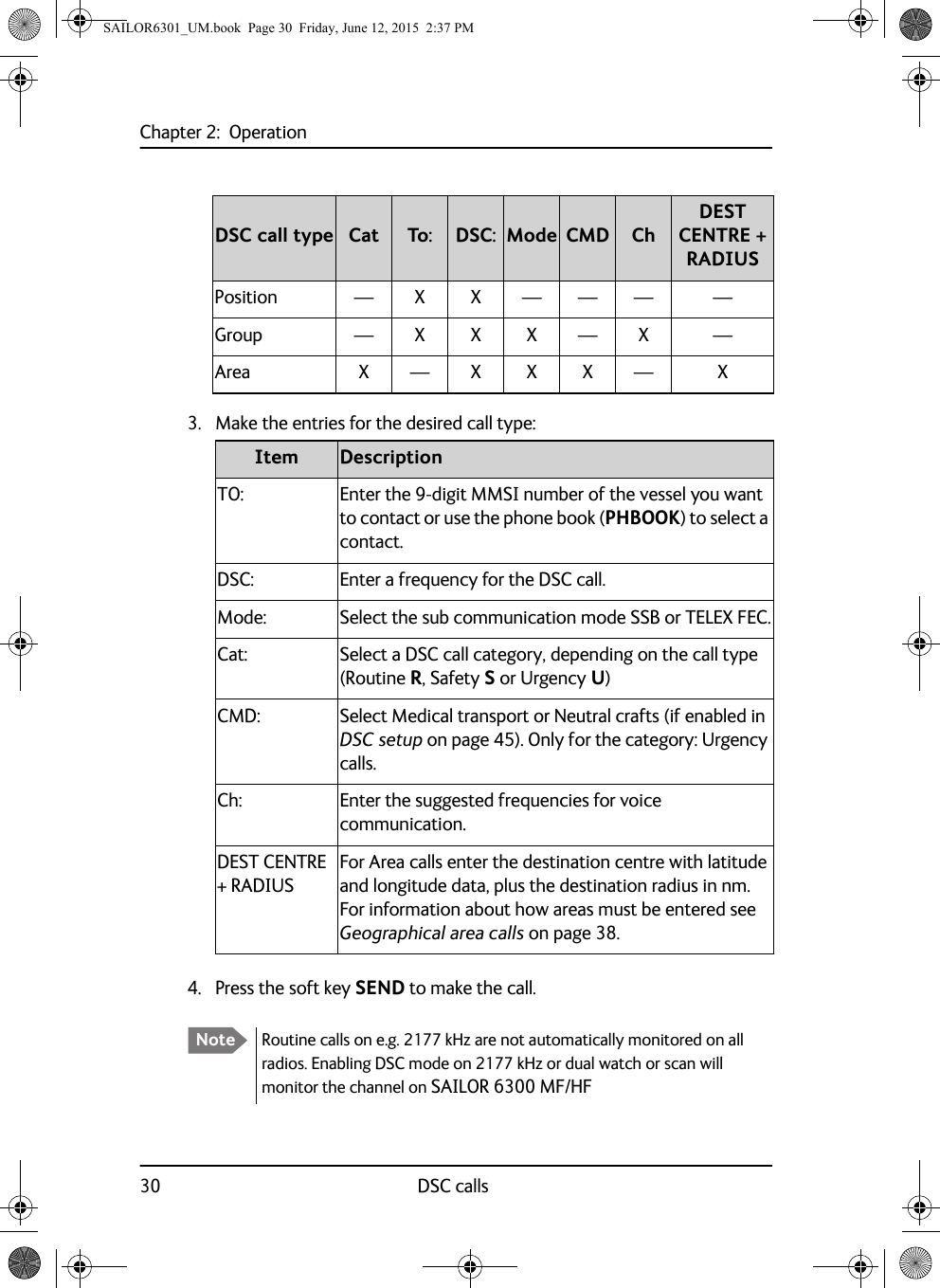
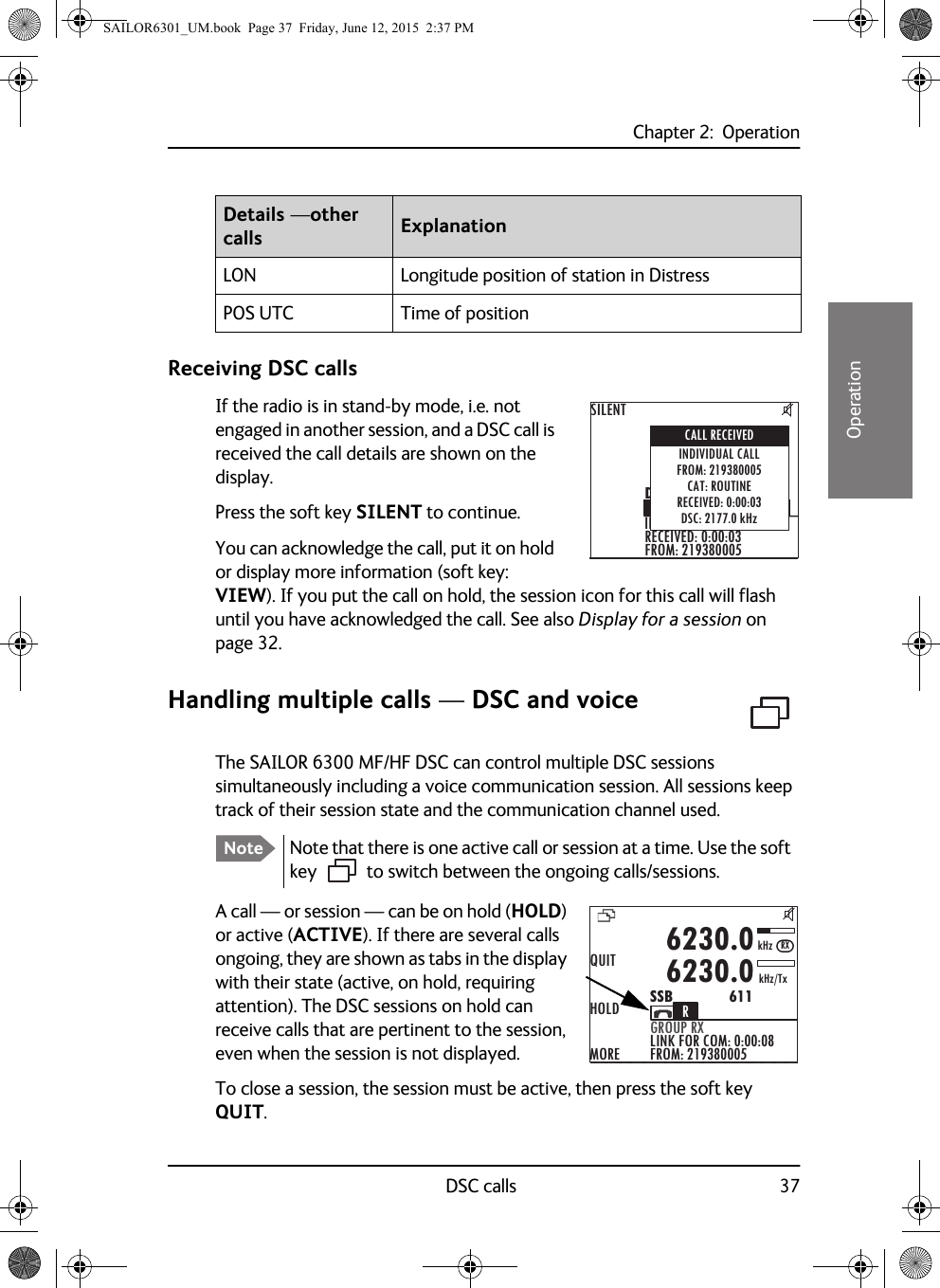
![Chapter 2: OperationBasic MF/HF radio communication 1922222OperationBasic MF/HF radio communicationYou can make radio calls using the Handset or another speaker device.• Ship-to-ship communication: Use simplex channels.• Ship-to-shore communication: Use duplex channels.Only valid frequencies and channel numbers are accepted. Selecting SSB telephony frequency1. Check that the MF/HF radio is in SSB mode. If necessary, press the button MODE to switch to SSB.2. Enter an RX and TX frequency, for example 2182 kHz, the international calling and Distress frequency for maritime radiotelephone communications on the marine MF bands.• First press on RX/TX button: Enter Rx frequency.• Second press on RX/TX button: Enter Tx frequency.• Long press on selector knob: Edit mode to fine-tune frequencies. In SSB mode (Voice clarify), in 10 Hz steps. One more press changes the step size to 100 Hz.Receiving a SSB telephony callWhen you hear your ship’s name or call sign in the loudspeaker. Proceed as follows:1. Take the Handset of the hook.2. Press the PTT button and wait until the tune icon has disappeared. The symbol TX shows that the radio is transmitting on the frequency displayed and the transmission power bar shows output power.3. Repeat the name of the station calling you and say: “This is [your ship’s name]”.CALLALERTDROBOSMOREMMSI: 123456789N 12°34.5678E 123°45.6789 GPS4357.04065.0SSB 401SQkHz/TxkHz/Rx22:07TuneSAILOR6301_UM.book Page 19 Friday, June 12, 2015 2:37 PM](https://usermanual.wiki/Thrane-and-Thrane-A-S/6300B.User-manual/User-Guide-2873613-Page-31.png)
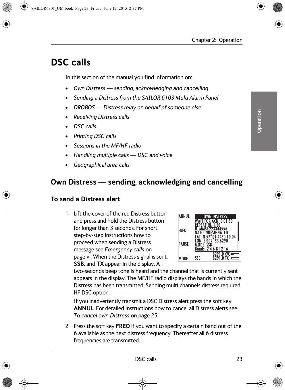
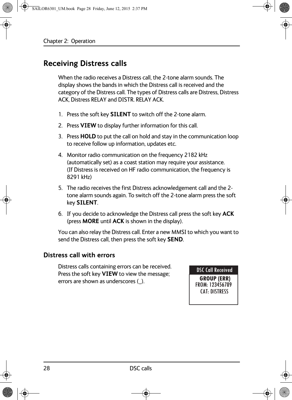
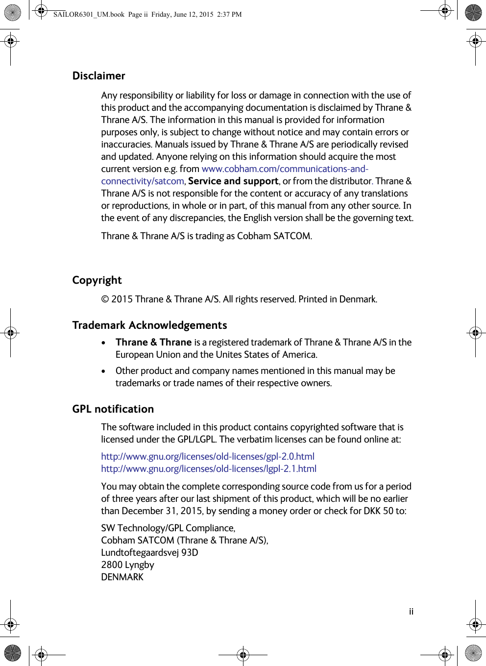
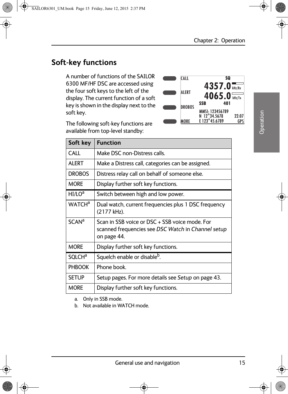
![Chapter 2: Operation20 Basic MF/HF radio communication4. Suggest a frequency pair by saying: “Frequencies [suggested frequencies]” and “Over.” and release the PTT button to allow the caller to confirm the suggested new frequencies.5. Switch to the new frequencies using the RX/TX button and the keypad and begin your conversation.Making a SSB telephony call1. Enter RX and TX frequencies or select an ITU channel.2. Lift the Handset or take a speaker device and press the PTT button, then wait until the tune icon has disappeared. The symbol TX shows that the radio is transmitting on the frequency displayed. The transmission power bar shows output power,3. Say the name of the station you are calling three times.Note The radio tunes first time you press the PTT button on a new frequency. As long as the tuning symbol is in the display, the radio is not transmitting. Wait until the tuning symbol has disappeared before talking. Tuning may take from 0.1 s to 8 s.TuneCALLALERTDROBOSMOREMMSI: 123456789N 12°34.5678E 123°45.6789 GPS4357.04065.0SSB 401SQkHz/TxkHz/Rx22:07Note If a popup window with the information TX inhibit is displayed when you want to make a radio call, your MF/HF radio is temporarily blocked for sending. Consult your radio responsible for information when you can start transmitting. SAILOR6301_UM.book Page 20 Friday, June 12, 2015 2:37 PM](https://usermanual.wiki/Thrane-and-Thrane-A-S/6300B.User-manual/User-Guide-2873613-Page-32.png)
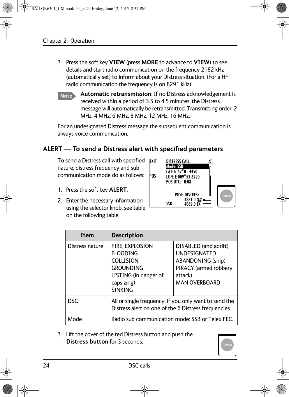
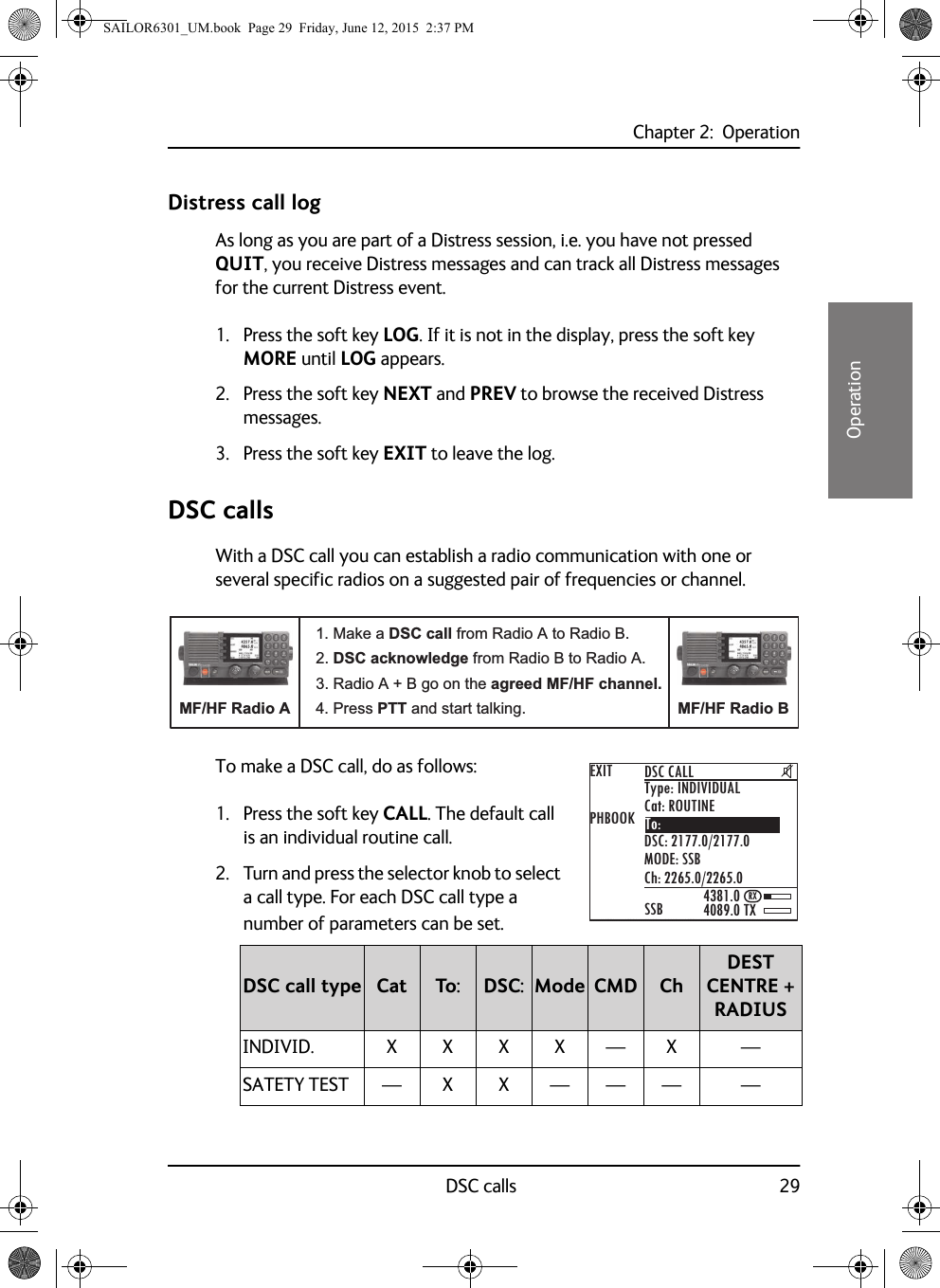
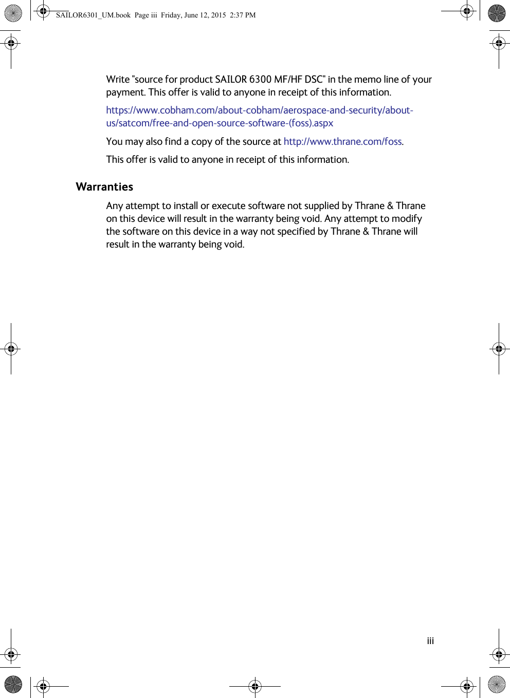
![Chapter 2: OperationWatch function 2122222Operation4. Say: “This is [your ship’s name]” and “Over.” and release the PTT button to listen. The symbol RX shows that the radio is receiving on the working channel displayed.5. When answered, agree upon a pair of frequencies, enter the new frequencies or ITU channel and start talking.Watch functionThe MF/HF radio has a dual watch function. The currently selected RX and TX frequencies and the routine DSC frequency 2177 kHz are watched.To start WATCH press the soft key WATCH. The display shows SSB-DW:2177.0 (example).To stop WATCH press the soft key WATCH.SAILOR6301_UM.book Page 21 Friday, June 12, 2015 2:37 PM](https://usermanual.wiki/Thrane-and-Thrane-A-S/6300B.User-manual/User-Guide-2873613-Page-33.png)