Thrane and Thrane A S 6300B Sailor 6366 TU MF/HF 150W DSC Class A FCC User Manual Bog 1 indb
Thrane & Thrane A/S Sailor 6366 TU MF/HF 150W DSC Class A FCC Bog 1 indb
Contents
- 1. User manual
- 2. Installation guide
- 3. Installation manual
- 4. Service interface manual
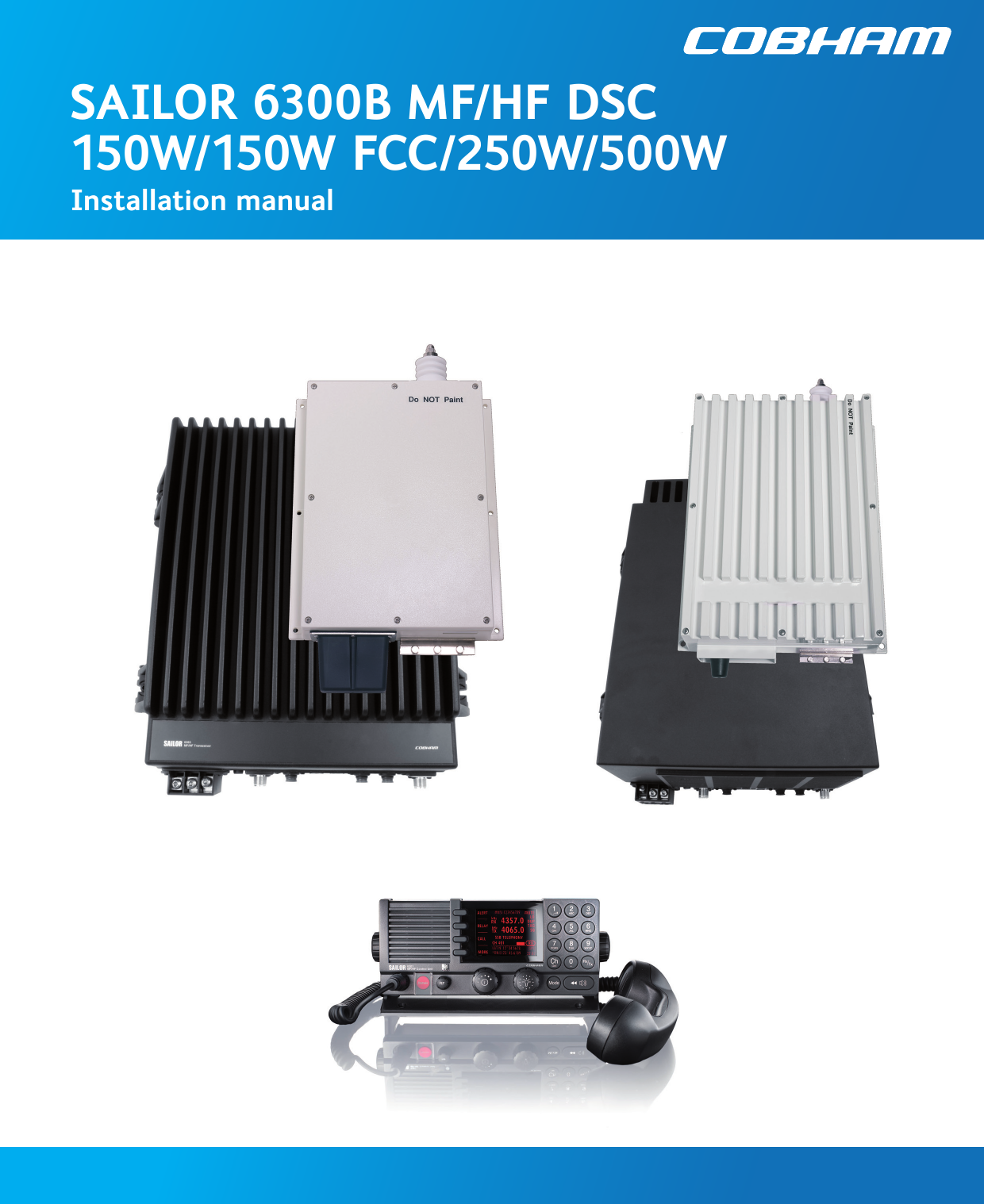
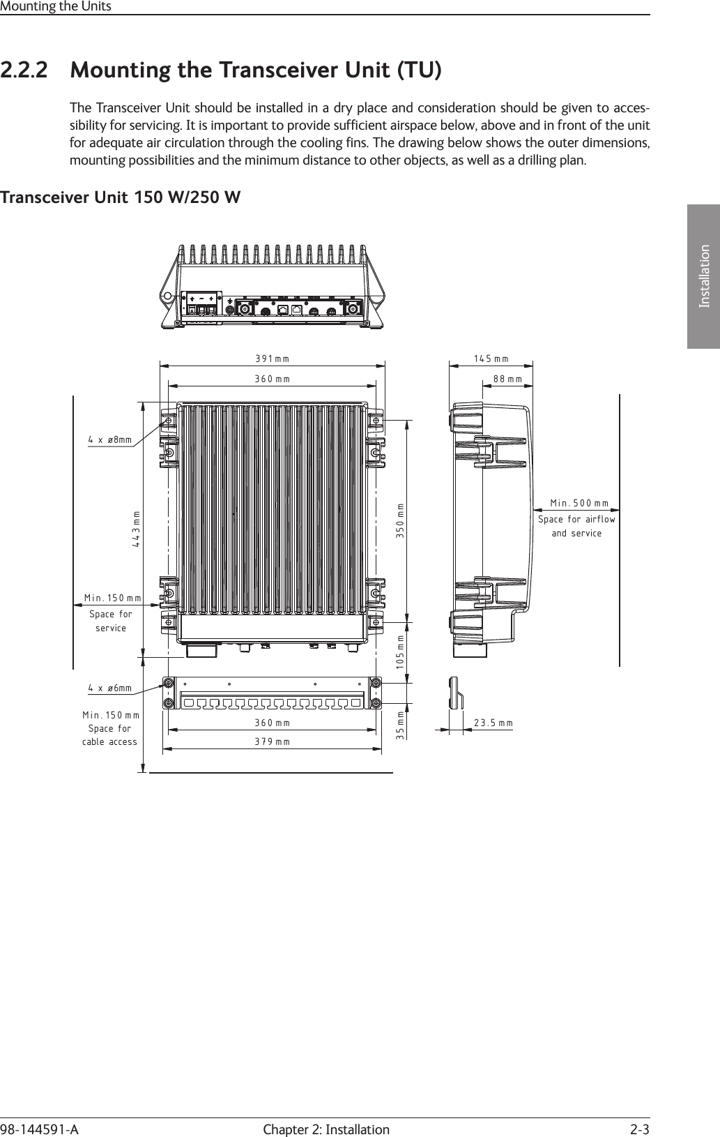
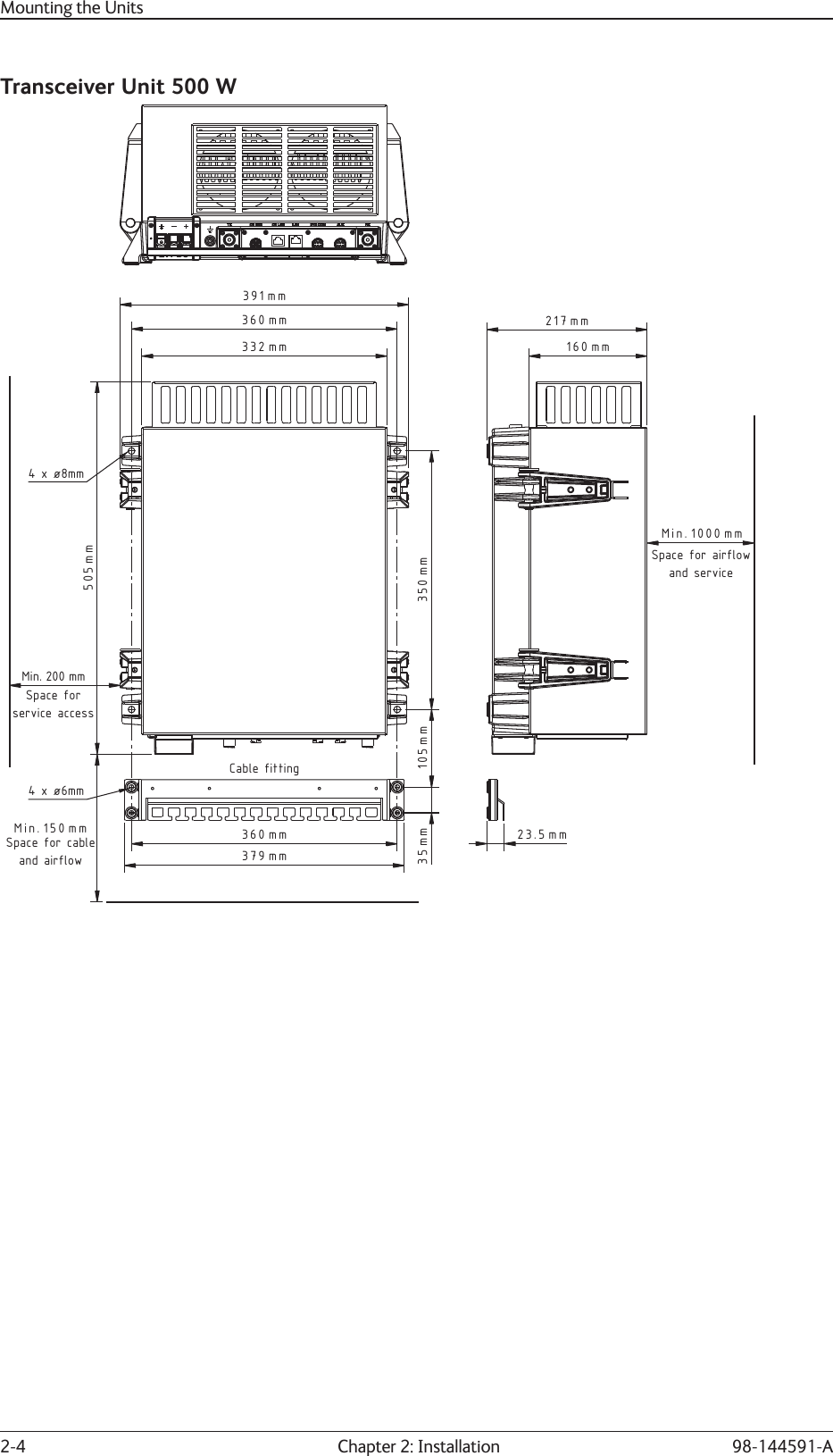
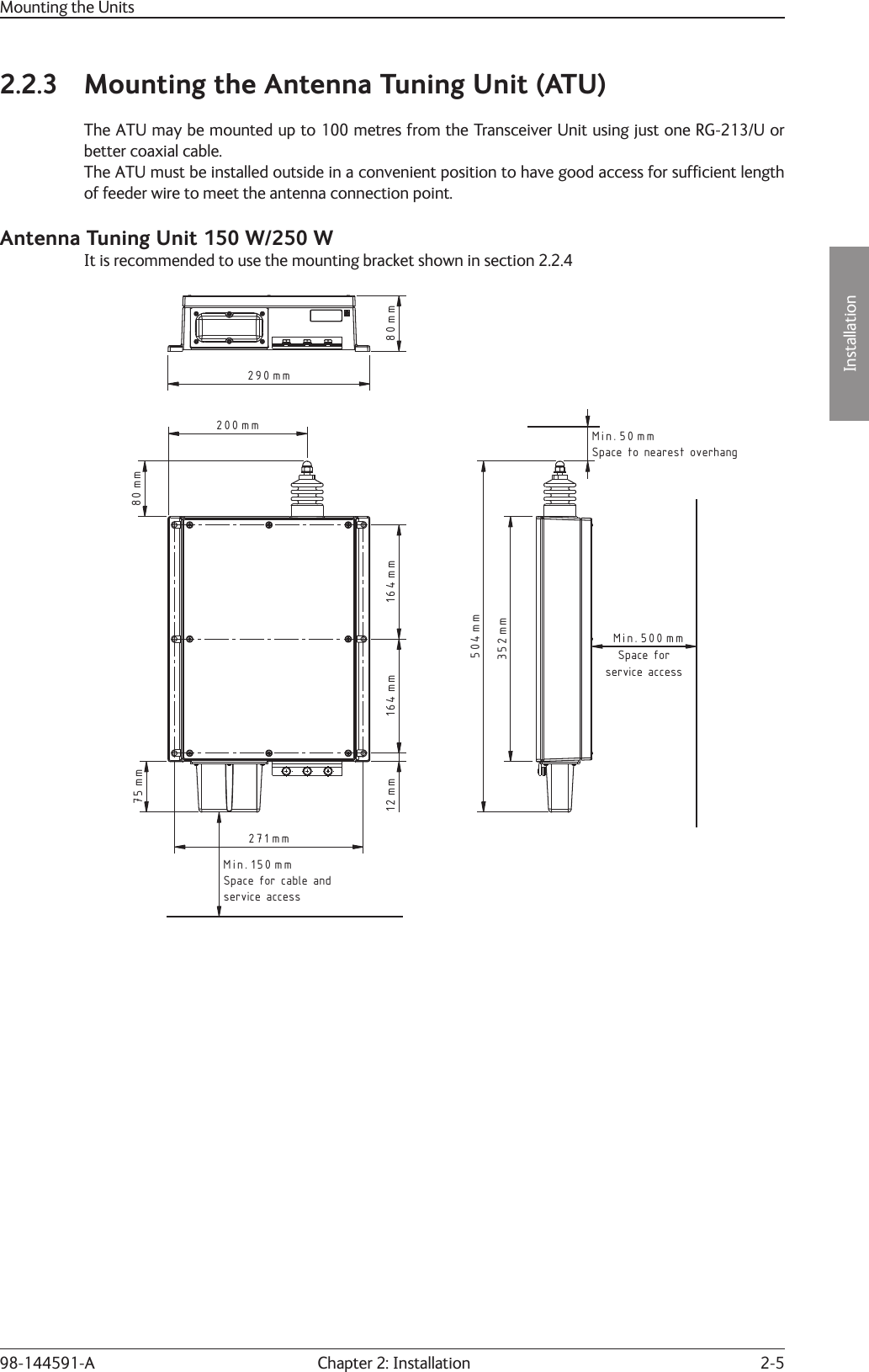
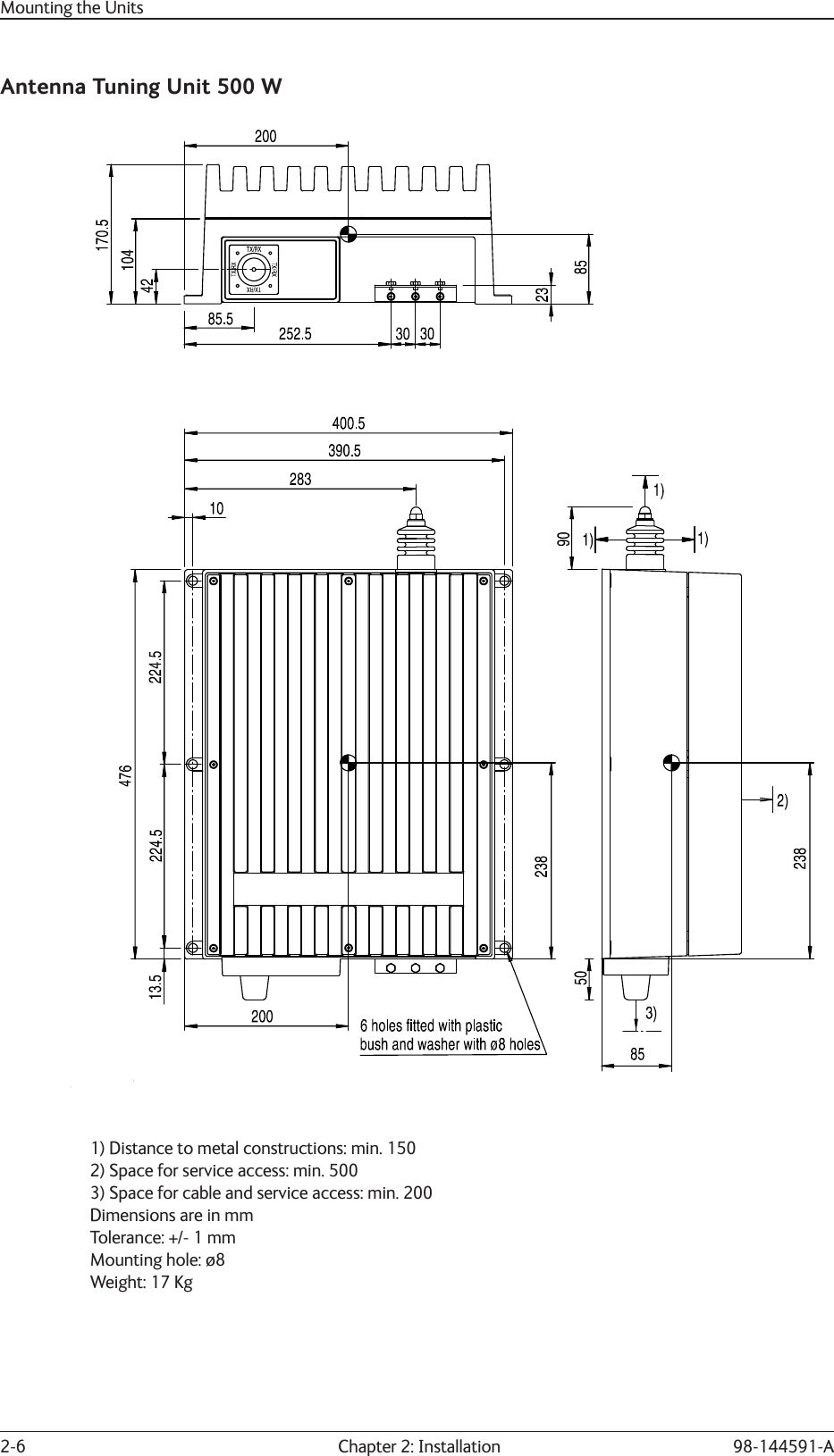
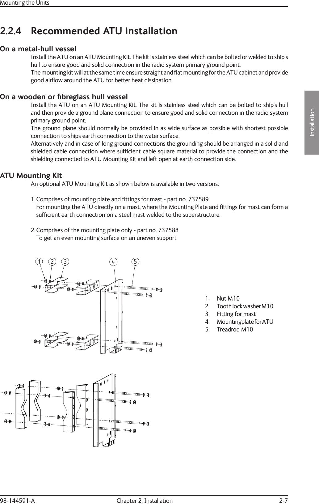
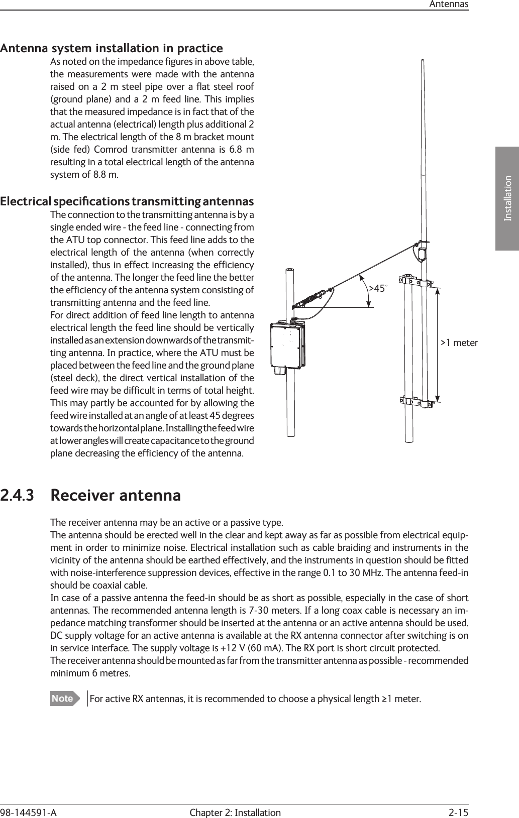
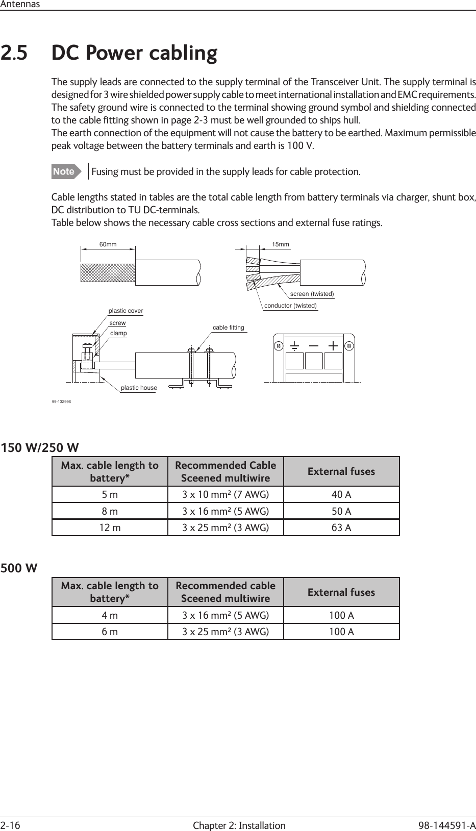
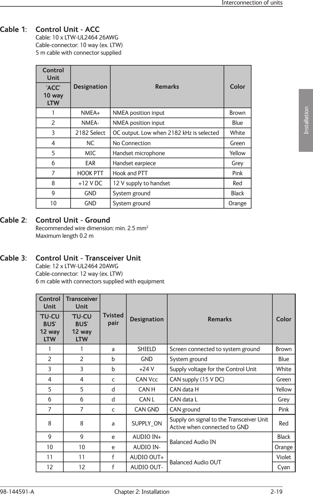
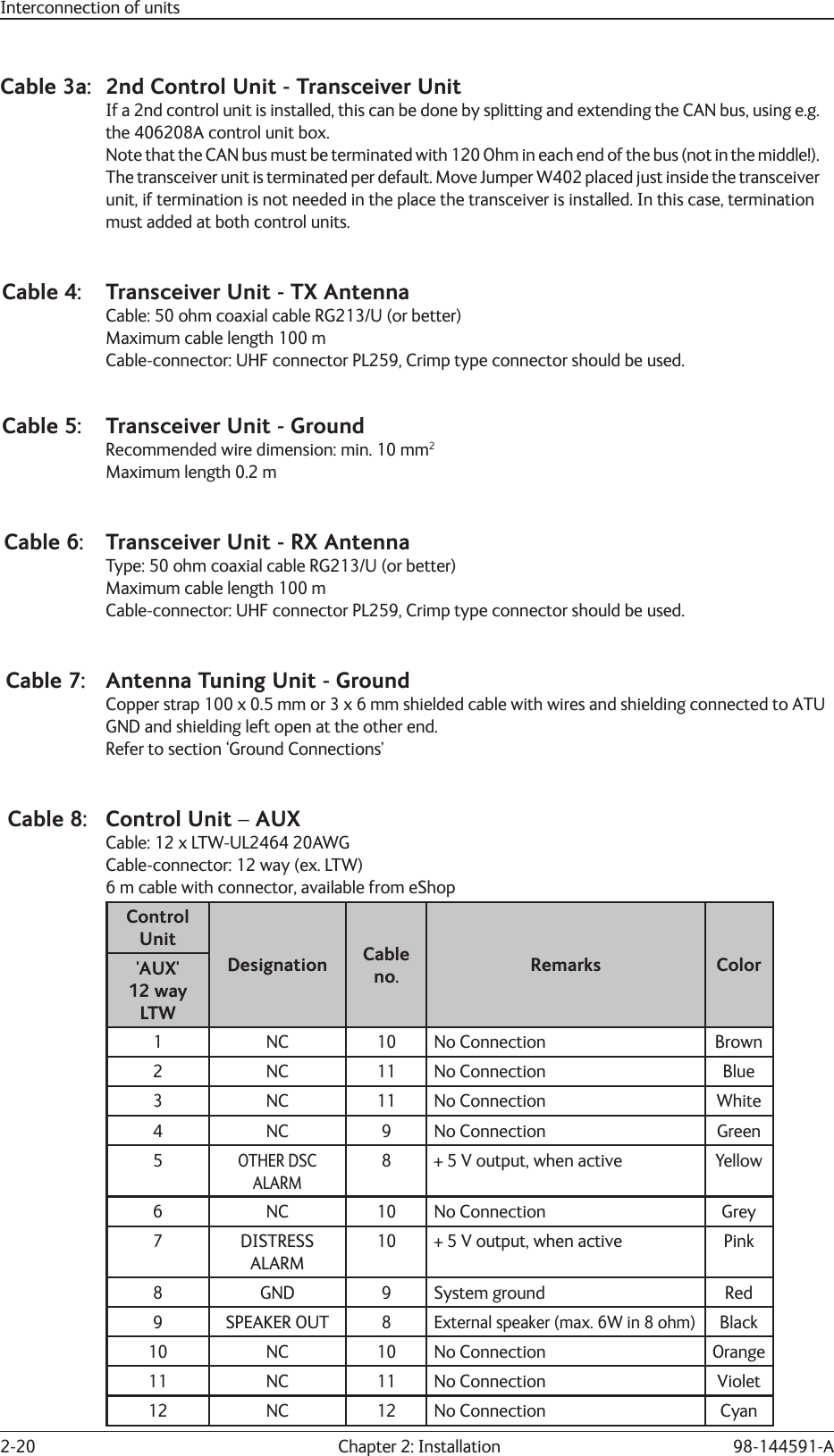
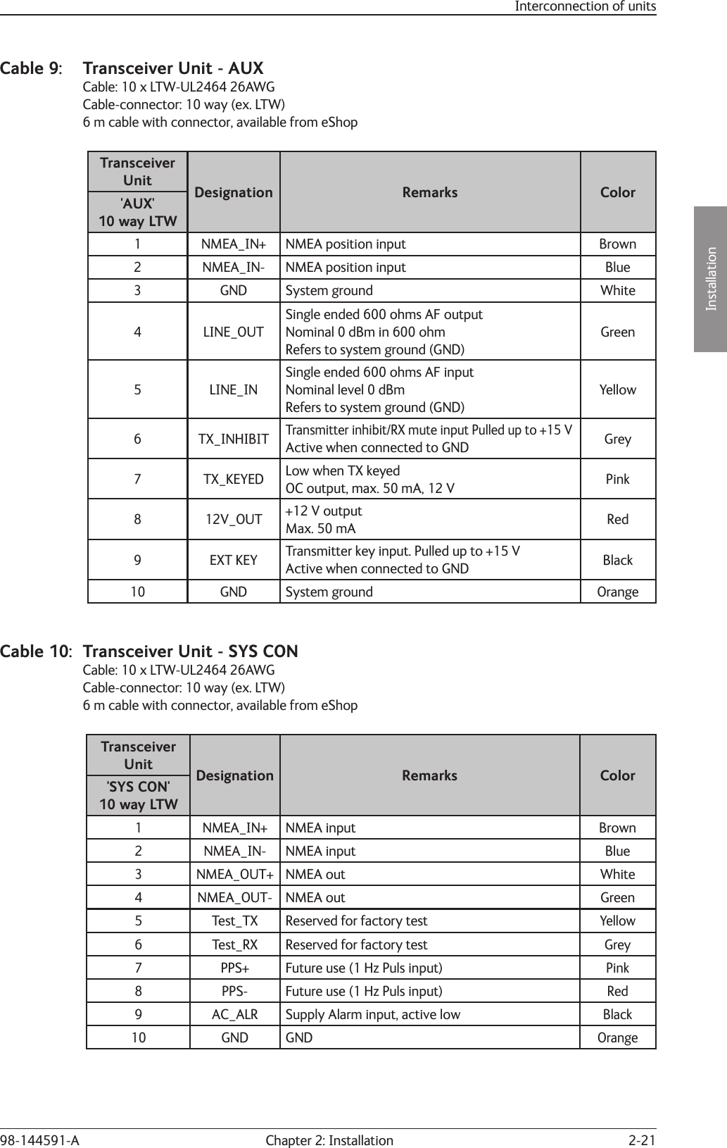
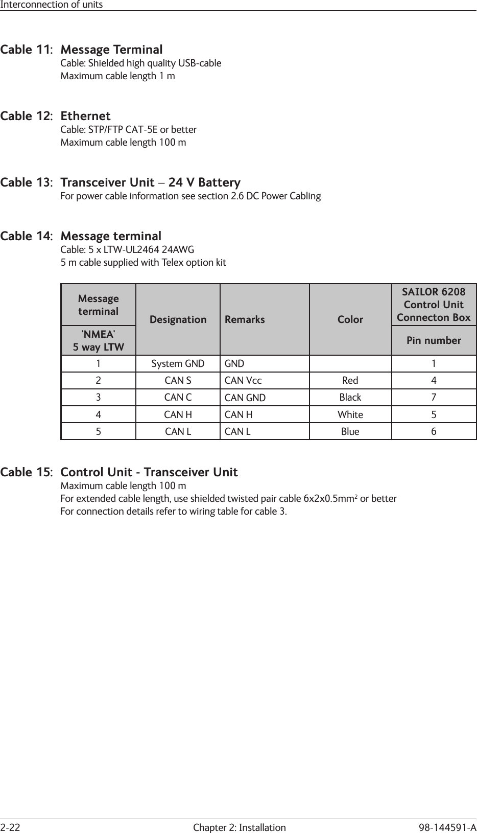
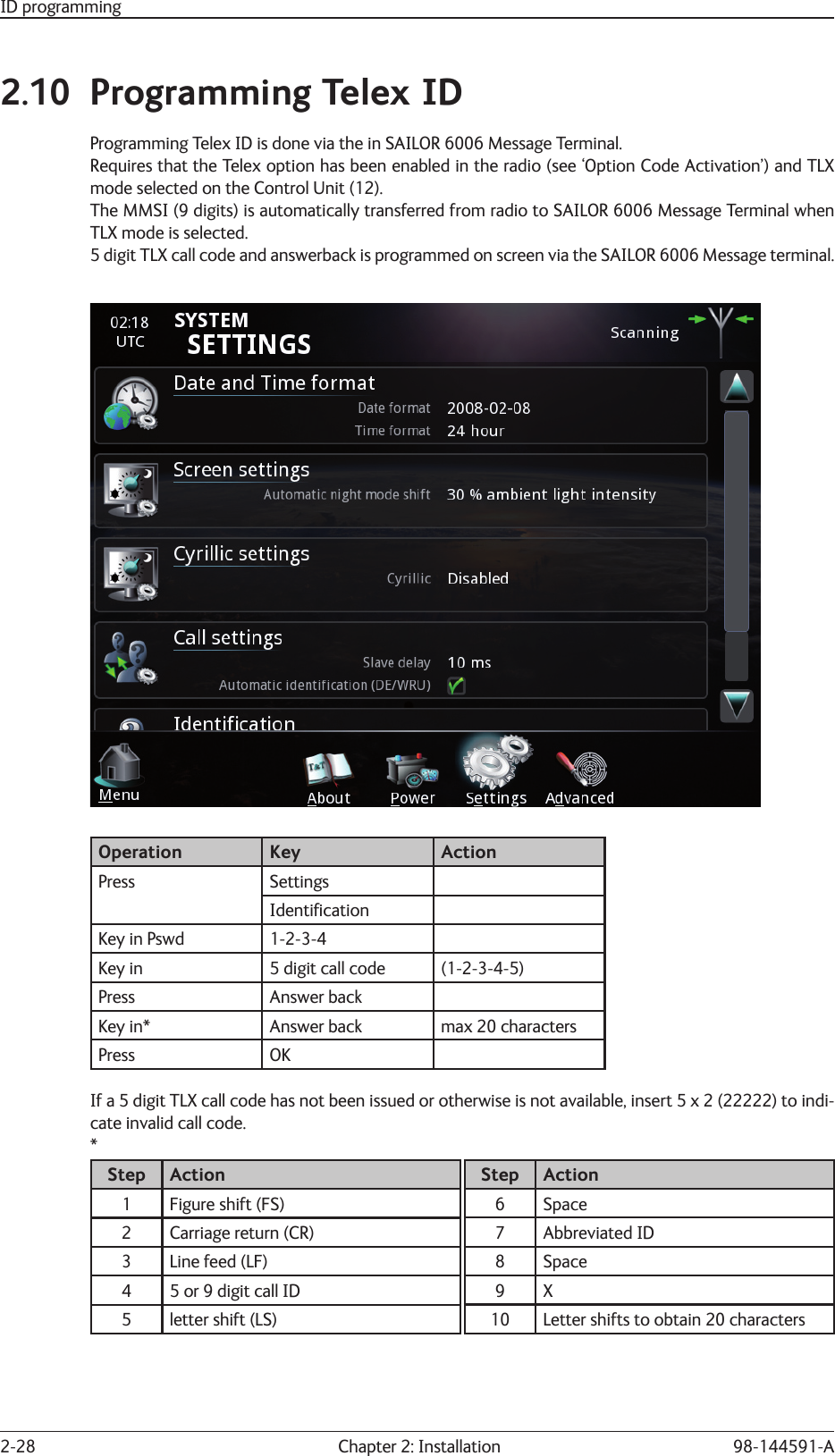
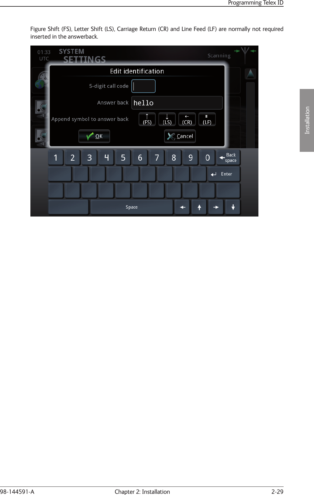
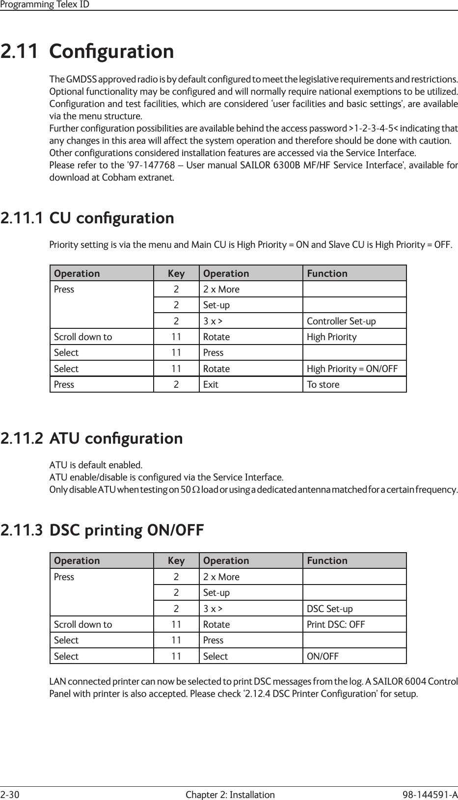
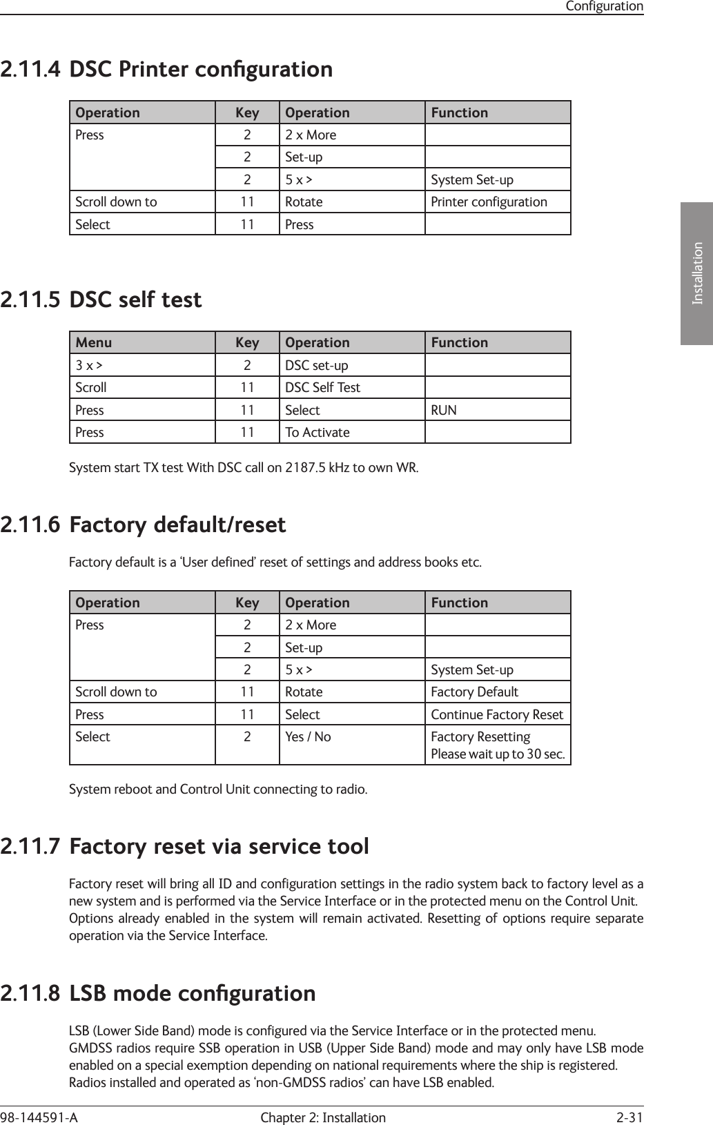
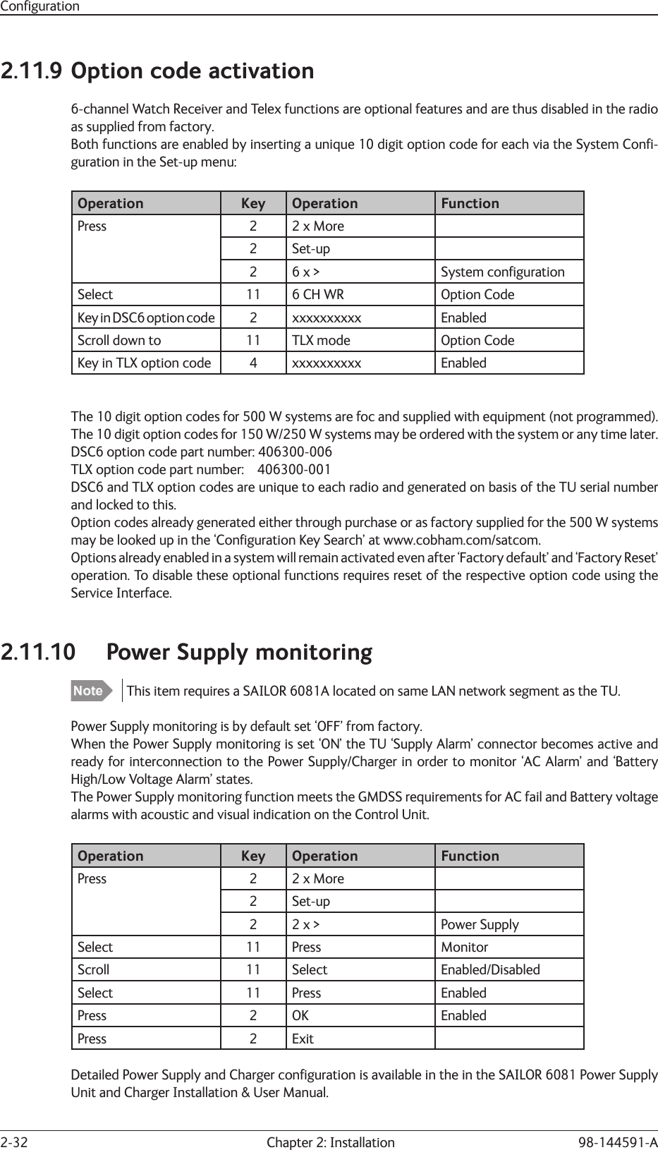
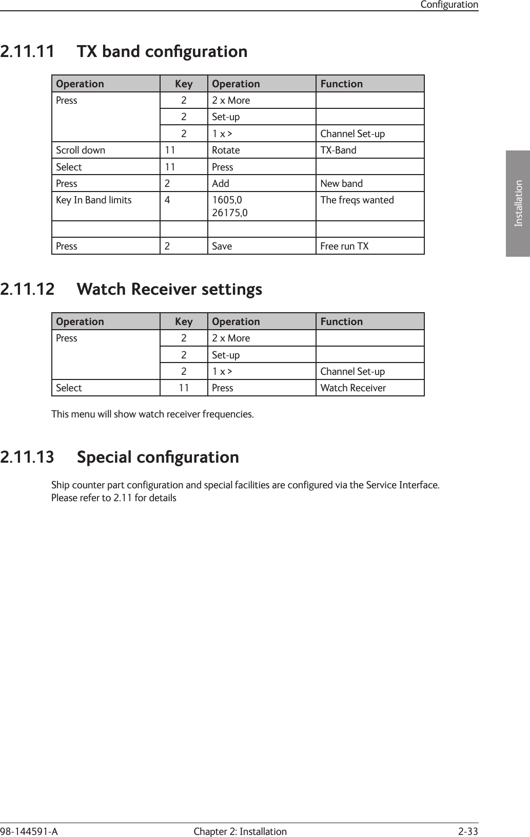
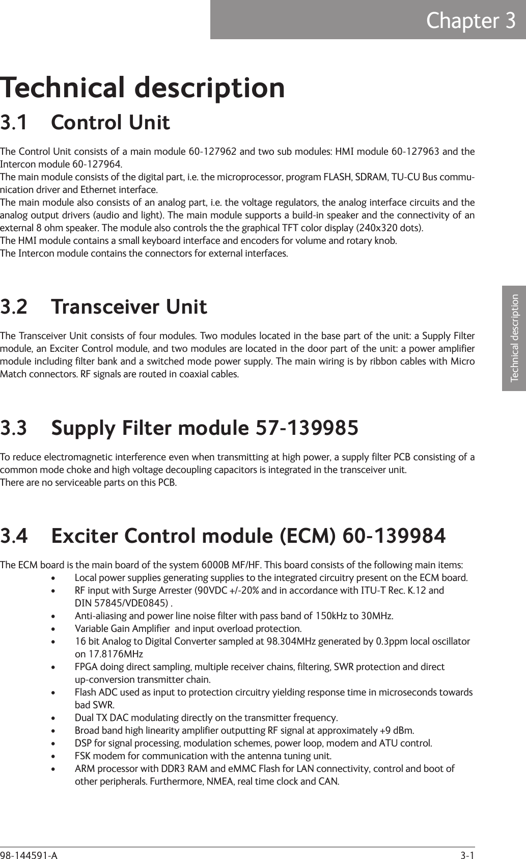
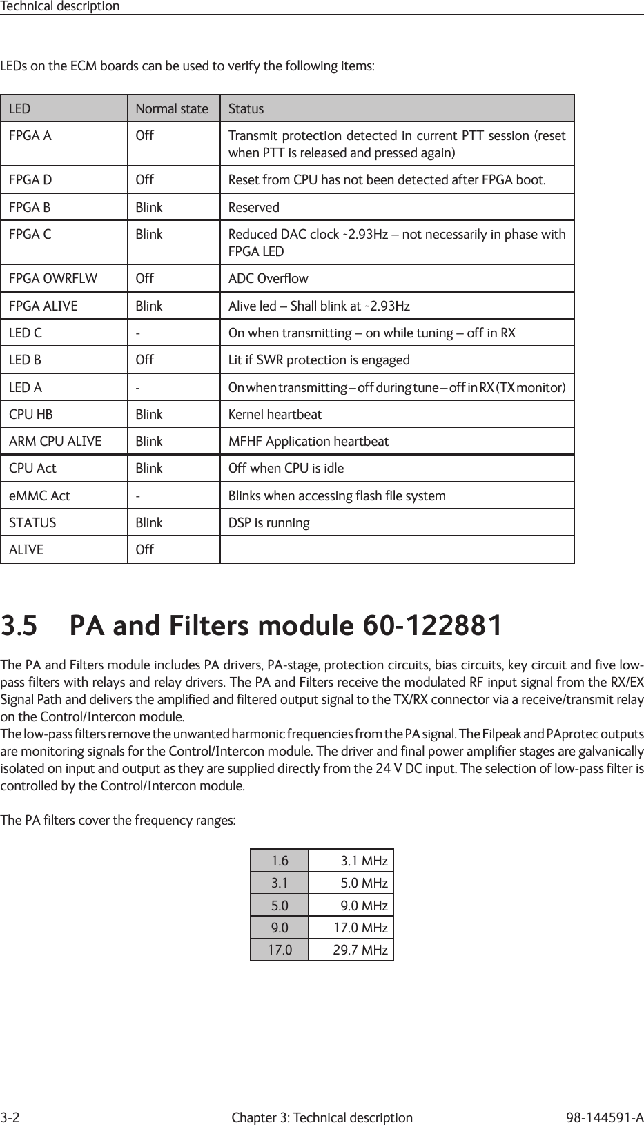
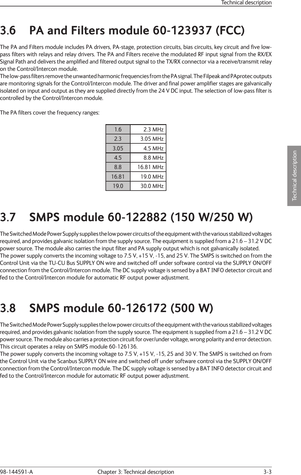
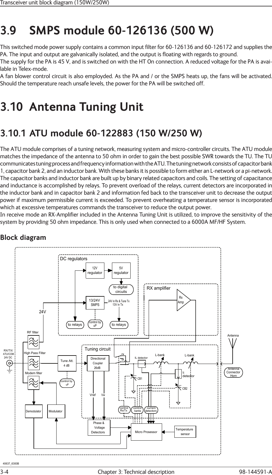
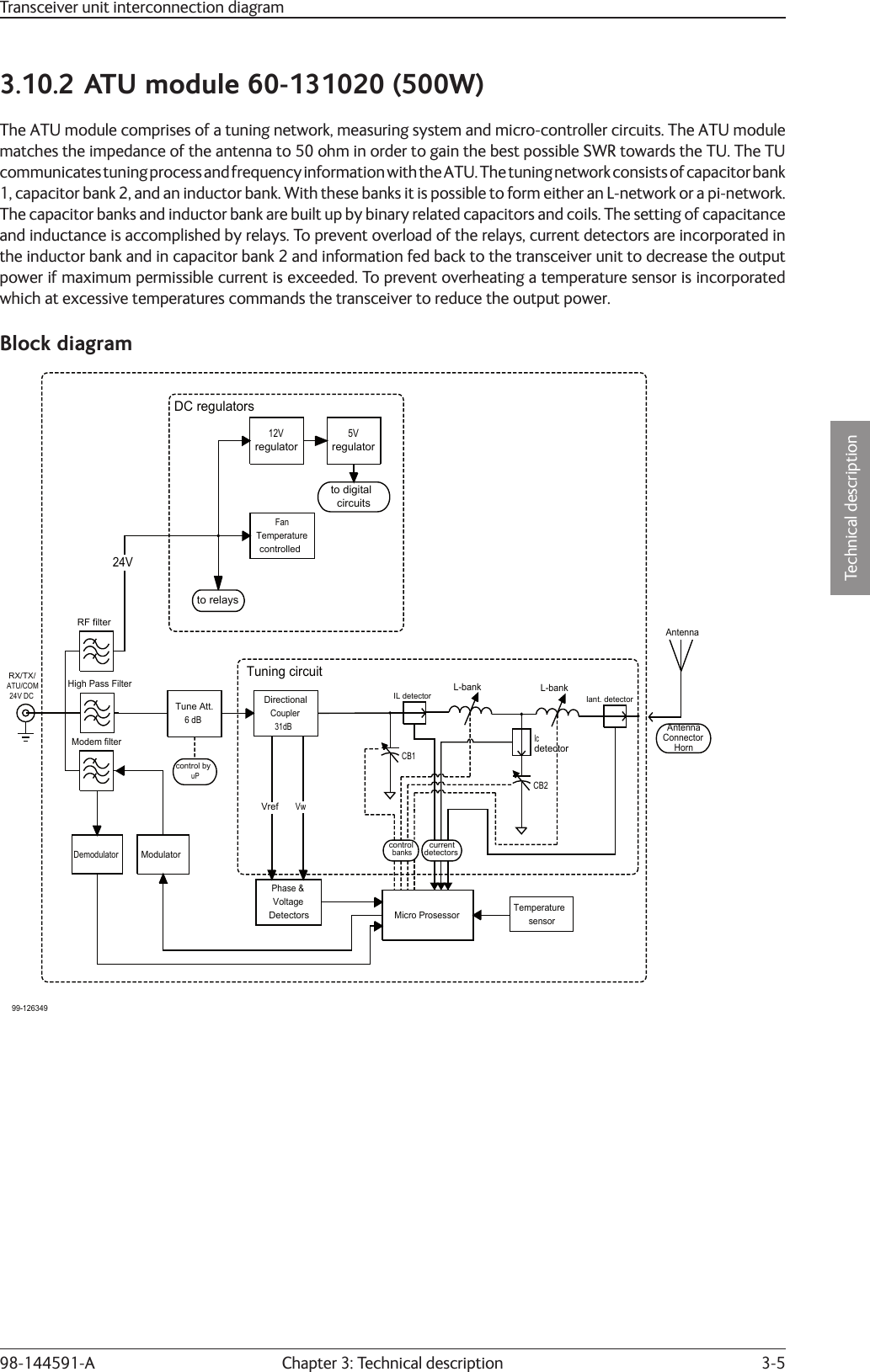
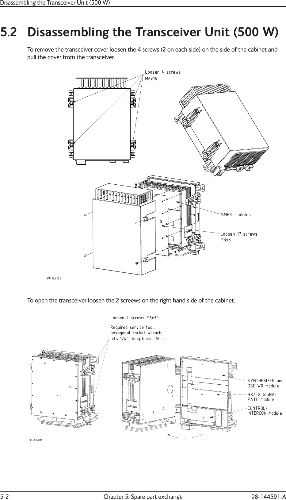
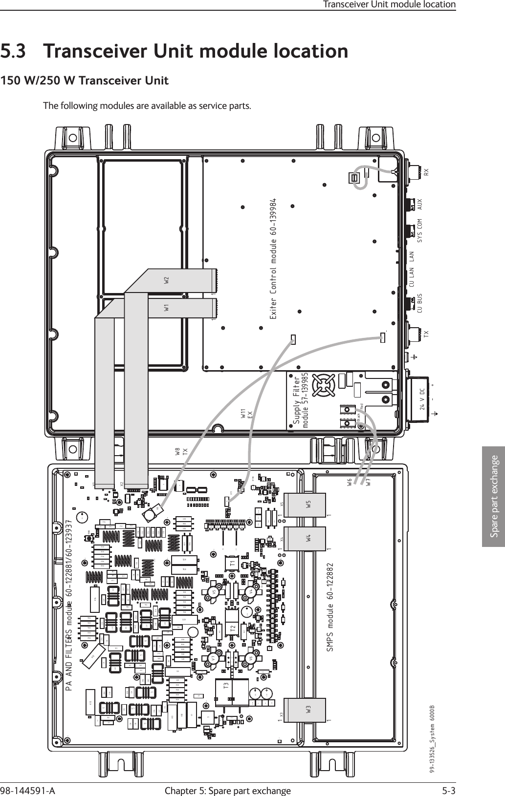
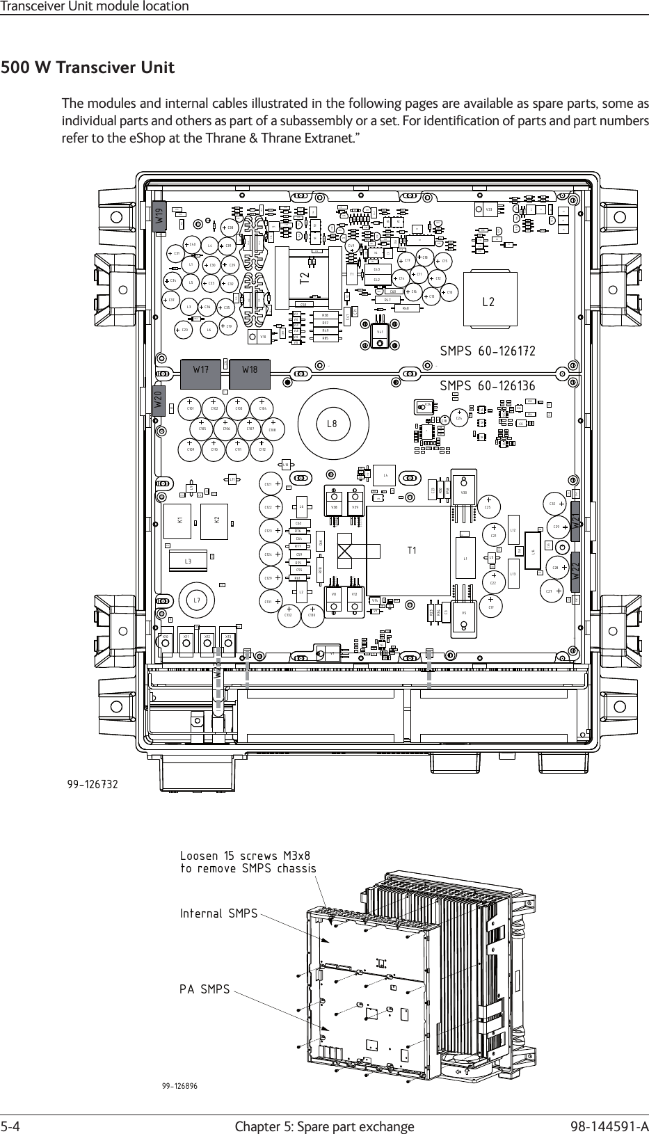
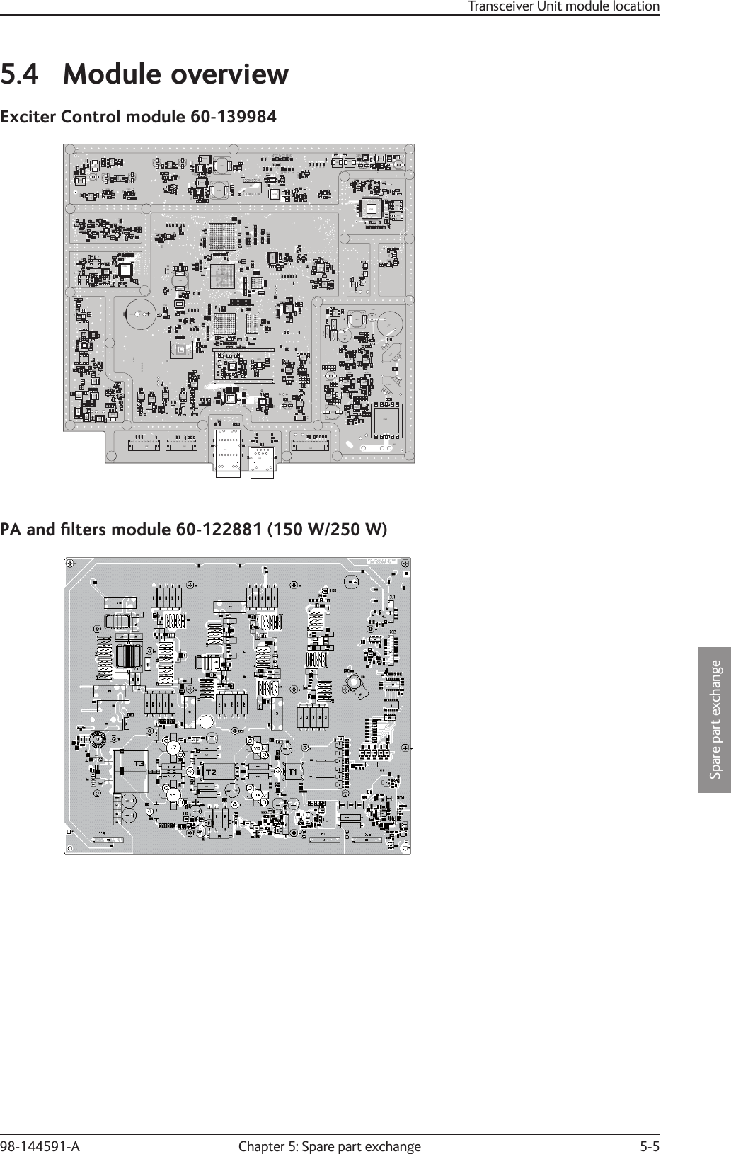
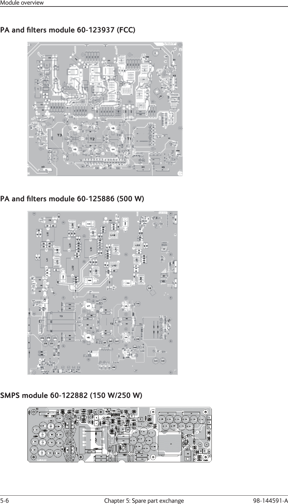
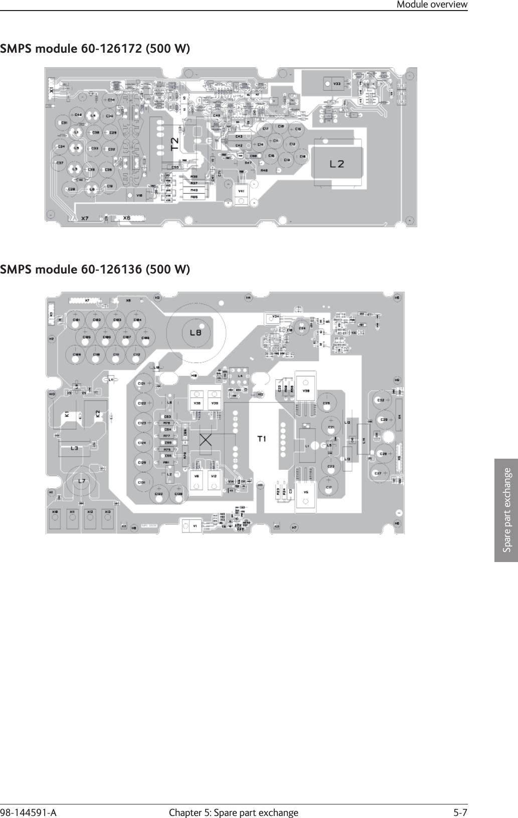
Installation manual