Thrane and Thrane A S 6300B Sailor 6366 TU MF/HF 150W DSC Class A FCC User Manual Bog 1 indb
Thrane & Thrane A/S Sailor 6366 TU MF/HF 150W DSC Class A FCC Bog 1 indb
Contents
- 1. User manual
- 2. Installation guide
- 3. Installation manual
- 4. Service interface manual
Installation manual
SAILOR 6300B MF/HF DSC
Installation manual
150W/150W FCC/250W/500W

Table of Contents
SAILOR 6300B MF/HF DSC
150W/150W FCC/250W/500W
Installation manual
Document number: 98-144591-A
Release date: October, 2015

98-144591-A
ii
Disclaimer
Any responsibility or liability for loss or damage in connection with the use of this product and the accompanying
documentation is disclaimed by Thrane & Thrane A/S. The information in this manual is provided for information
purposes only, is subject to change without notice and may contain errors or inaccuracies. Manuals issued by Thrane &
Thrane A/S are periodically revised and updated. Anyone relying on this information should acquire the most current
version e.g. from www.cobham.com/communications-and-connectivity/satcom, Service and support, or from the
distributor. Thrane & Thrane A/S is not responsible for the content or accuracy of any translations or reproductions, in
whole or in part, of this manual from any other source. In the event of any discrepancies, the English version shall be the
governing text.
Thrane & Thrane A/S is trading as Cobham SATCOM.
Copyright
© 2014 Thrane & Thrane A/S. All rights reserved.
Trademark Acknowledgements
• Thrane & Thrane is a registered trademark of Thrane & Thrane A/S in the European Union and the Unites
States of America.
• SAILOR is a registered trademarks of Thrane & Thrane A/S.
• Other product and company names mentioned in this manual may be trademarks or trade names of their
respective owners.

iii98-144591-A
Safety summary
The following general safety precautions must be observed during all phases of operation, service and repair of this
equipment. Failure to comply with these precautions or with specifi c warnings elsewhere in this manual violates
safety standards of design, manufacture and intended use of the equipment. Thrane & Thrane assumes no liability
for the customer's failure to comply with these requirements.
GROUND THE EQUIPMENT
To minimise shock hazard, the equipment chassis and cabinet must be connected to an electrical ground and the
cable instructions must be followed.
DO NOT OPERATE IN AN EXPLOSIVE ATMOSPHERE
Do not operate the equipment in the presence of fl ammable gases or fumes.
Operation of any electrical equipment in such an environment constitutes a defi nite safety hazard.
KEEP AWAY FROM LIVE CIRCUITS
Operating personnel must not remove equipment covers. Component replacement and internal adjustment must be
made by qualifi ed maintenance personnel. Do not service the unit with the power cable connected. Always discon-
nect and discharge circuits before touching them.
Service
General service must be done by skilled service personnel.
Caution! Only skilled service personnel may service and repair the equipment.
Always carry out work under ESD safe conditions.

98-144591-A
iv
RF exposure hazards and instructions
Your Thrane & Thrane radio generates electromagnetic RF (radio frequency) energy when transmitting. To ensure
that you and those around you are not exposed to excessive amounts of energy and thus to avoid health hazards
from excessive exposure to RF energy, all persons must obey the following:
Caution! Never touch the horn of the Antenna Tuning Unit or feeder wire when
the MF/HF
radio is transmitting. High voltage which can cause death
or serious injury is present at the locations shown in the illustration
below.
Warranty limitation
The radio is not a user maintainable unit, and under no circumstances should the unit be opened except by authorized
personnel. Unauthorized opening of the unit will invalidate the warranty.
Unit
Antenna Tuning
MF/HF
SAILOR 638x

v98-144591-A
Record of revisions
Rev. Description Relase Date Initials
A Original document October 2015 CMA
Preface
Radio for occupational use
The SAILOR 6300B MF/HF DSC fulfi ls the requirements of the SOLAS directive and is intended for use in maritime
environment.
SAILOR 6300B MF/HF DSC is designed for occupational use only and must be operated by licensed personnel only.
SAILOR 6300B MF/HF DSC is not intended for use in an uncontrolled environment by general public.
Training information (for FCC approved equipment)
The SAILOR 6300B MF/HF DSC is designed for occupational use only and is also classifi ed as such. It must be ope-
rated by licensed personnel only. It must only be used in the course of employment by individuals aware of both
the hazards as well as the way to minimize those hazards.
The radio is thus NOT intended for use in an uncontrolled environment by general public. The SAILOR 6300 MF/HF
DSC has been tested and complies with the FCC RF exposure limits for Occupational Use Only. The radio also com-
plies with the following guidelines and standards regarding RF energy and electromagnetic energy levels including
the recommended levels for human exposure:
• FCC OET Bulletin 65 Supplement C, evaluating compliance with FCC guidelines for human exposure to radio
frequency electromagnetic fi elds.
• American National Standards Institute (C95.1) IEEE standard for safety levels with respect to human exposure
to radio frequency electromagnetic fi elds, 3 kHz to 300 GHz
• American National Standards Institute (C95.3) IEEE recommended practice for the measurement of potentially
hazardous electromagnetic fi elds - RF and microwaves.
Below the RF exposure hazards and instructions in safe operation of the radio within the FCC RF exposure limits
established for it are described.
Warning
Your Thrane & Thrane radio set generates electromagnetic RF (radio frequency) energy when it is transmitting. To
ensure that you and those around you are not exposed to excessive amounts of that energy (beyond FCC allowable
limits for occupational use) and thus to avoid health hazards from excessive exposure to RF energy, FCC OET bulletin
65 establishes an Maximum Permissible Exposure (MPE) radius of 6 ft. (1.8 m) for the maximum power of your radio
(150 W selected) with a whip antenna having a maximum gain of 3.0 dBi.
The safety distance from the antenna is stated to:
Antenna Safety distance
150W 6 ft. which are equal to 184 cm > 156 cm
250W 7 ft. which are equal to 215 cm > 201 cm
500W 10 ft. which are equal to 307 cm > 285 cm

98-144591-A
vi
Installation
1. A whip antenna with a maximum gain of 3 dBi must be mounted at least 12.6 ft. (3.9m) above the highest deck
where people may be staying during radio transmissions. The distance is to be measured vertically from the
lowest point of the antenna. This provides the minimum separation distance which is in compliance with RF
exposure requirements and is based on the MPE radius of 6 ft. (1.8m) plus the 6.6 ft. (2.0 m) height of an adult.
2. On vessels that cannot fulfi l requirements in item 1, the antenna must be mounted so that its lowest point is
at least 6 ft. (1.8m) vertically above the heads of people on deck and all persons must be outside the 6 ft. (1.8
m) MPE radius during radio transmission.
• Always mount the antenna at least 6 ft (1.8 m) from possible human access.
• Never touch the antenna when transmitting
• Use only authorized T&T accessories.
3. If the antenna has to be placed in public areas or near people with no awareness of the radio transmission, the
antenna must be placed at a distance not less than 12 ft. (3.6 m) from possible human access.
Failure to observe any of these warnings may cause you or other people to exceed FCC RF exposure limits or create
other dangerous conditions.
Related documents
Title and description Document number
Installation guide SAILOR 630x MF/HF Control Unit 98-132396
Installation guide SAILOR 6300B MF/HF Transceiver Unit & Antenna Tuning Unit
150 W/250 W/500 W
98-144542
User Manual SAILOR 6301 MF/HF Control Unit 98-131070
User Manual SAILOR 6300 MF/HF Radiotelex 98-132519
Installation and user manual SAILOR 6101 and 6103 Alarm Panel 98-130981
Emergency call sheet 98-132369

Table of Contents
vii
98-144591-A
Chapter 1 General information
1.1 Introduction .............................................................................................................................1-1
1.2 Technical data ...........................................................................................................................1-1
Chapter 2 Installation
2.1 Description .................................................................................................................................2-1
2.2 Mounting the units .................................................................................................................2-1
2.3 Ground connections .............................................................................................................2-9
2.4 Antennas .....................................................................................................................................2-12
2.5 DC Power cabling ...................................................................................................................2-16
2.6 Interconnection of units .....................................................................................................2-17
2.7 Position and time information ..........................................................................................2-23
2.8 Telex operation ........................................................................................................................2-24
2.9 ID Programming .......................................................................................................................2-25
2.10 Programming Telex ID .........................................................................................................2-28
2.11 Confi guration ...........................................................................................................................2-30
2.12 Final installation check .........................................................................................................2-33
Chapter 3 Technical description
3.1 Control Unit ...............................................................................................................................3-1
3.2 Transceiver Unit .......................................................................................................................3-1
3.3 Supply Filter module 57-139985 ....................................................................................3-1
3.4 Exciter Control module (ECM) 60-139984 ...............................................................3-1
3.5 PA and Filters module 60-122881..................................................................................3-2
3.6 PA and Filters module 60-123937 (FCC) ...................................................................3-3
3.7 SMPS module 60-122882 (150 W/250 W) ...............................................................3-3
3.8 SMPS module 60-126172 (500 W) ...............................................................................3-3
3.9 SMPS module 60-126236 (500 W) ...............................................................................3-3
3.10 Antenna Tuning Unit ............................................................................................................3-4
3.11 Power control and protection system ...........................................................................3-6
Table of Contents

98-144591-A
viii
Table of Contents
Chapter 4 Service
4.1 Preventive maintenance .....................................................................................................4-1
4.2 Cleaning the Air fi lter (500 W Transceiver only) ......................................................4-1
4.3 System test and verifi cation ..............................................................................................4-2
4.4 Software update ......................................................................................................................4-2
Chapter 5 Spare part exchange
5.1 Disassembling the Transceiver Unit (150 W/250 W) ............................................5-1
5.2 Disassembling the Transceiver Unit (500 W) ............................................................5-2
5.3 Transceiver Unit module location ...................................................................................5-3
5.4 Module overview .....................................................................................................................5-5
5.5 Required service tools ...........................................................................................................5-8
5.6 Accessory list ............................................................................................................................5-8
Glossary ................................................................................................................... Glossary-1

Chapter 1: General information 1-1
General information
98-144591-A
Technical data
General information
1.1 Introduction
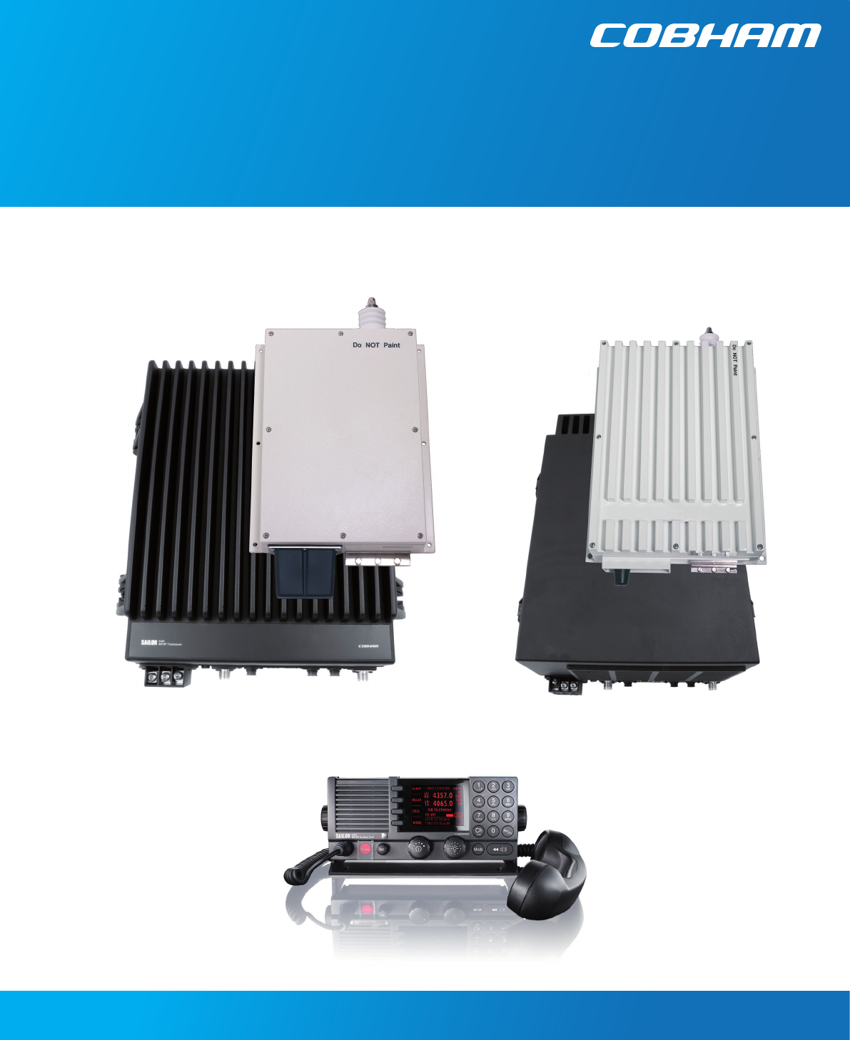
The 150 W/250 W/500 W MF/HF transceiver with integrated DSC and telex (NBDP) is designed for mari-
time applications in voluntary as well as compulsorily fi tted vessels. It offers simplex and semi-duplex
SSB radiotelephone communication in the maritime mobile frequency bands between 1.6 and 30 MHz.
The basic version of the transceiver includes voice, DSC and a dedicated 2187.5 KHz DSC watch receiver,
forming an ideal system for MF GMDSS installations.
The equipment consists of a compact transceiver control unit, a fully remote controlled transceiver unit
and an automatic antenna tuning unit.
The microprocessor controlled Antenna Tuning Unit automatically matches the impedance of antennas
between 8 and 18 metres in length and requires no presetting at the installation. It is designed for outdoor
installation and may be located up to 100 metres from the Transceiver Unit.
The Transceiver Unit contains all receiver and transmitter circuits. The fully protected solid state 150 W/
250 W /500 W power amplifi er matches a 50 ohm antenna system, but is normally used in connection
with the Antenna Tuning Unit. The DSC/Telex modem contains two demodulators, one connected to the
built-in watch receiver for continuous watch on the DSC distress frequencies, the other connected to
the communication receiver which may be used to keep simultaneous watch on other DSC frequencies
or telex communication.
The transceiver can be upgraded to scan 6 DSC channels, and Telex operation to comply with MF/HF
requirements in sea area A4. Codes are purchased as accessories for the system.
The Control Unit is for operation of radiotelephony as well as DSC and confi guration. Use of the equip-
ment is simple, logic and straight forward. DSC operation is based on the use of soft keys. Guiding texts
are provided and the large display is able to show the contents of a complete call in one screen.
For telex operation the Message Terminal must be connected to the system via the CAN bus.
The equipment is designed for operation from a 24 V DC supply, like e.g. a battery. With the optional AC
Power Supply unit installed the equipment may be supplied from 115/230 V AC main or emergency sup-
plies with automatic switch-over to 24 V DC supply in the absence of AC supply voltage. Also optionally, a
battery charger for AC is available in the product line.
The built-in test facilities and easy-to-replace module design of the equipment simplifi es the service concept.
1.2 Technical data
1.2.1 General
Complies with the relevant IMO performance standards for MF, MF/HF, MSI, and NBDP GMDSS equipment,
the ITU Radio Regulations, the ITU-R recommendations and the relevant performance specifi cations of
ETSI, IEC and FCC, in the ITU marine bands.
Operating modes: Simplex and semi-duplex SSB telephony (J3E), DSC (J2B), AM broadcast
reception (H3E) and Telex (J2B)
Frequency stability: Better than 0.35 ppm
Warm-up time. Less than one minute
Ageing less than 0.1 ppm/year
Normal operating
temperature: from 0°C to +40°C
Extreme operating
temperature: From -15°C to +55°C
ATU From -25°C to +55°C
User-programmable
channels: 199 frequency pairs with mode (1-199)
Chapter 1: General information
Chapter 1
1-2 Chapter 1: General information 98-144591-A
Technical data
User-programmable
stations: 40 stations with name, MMSI and station channel
Supply voltage: Nominal 24V DC (-10 +30% — 21.6 - 31.2 V DC)
With optional external AC power supply:
115/230V AC 50/60 Hz. Automatic change-over to DC in the absence of AC supply
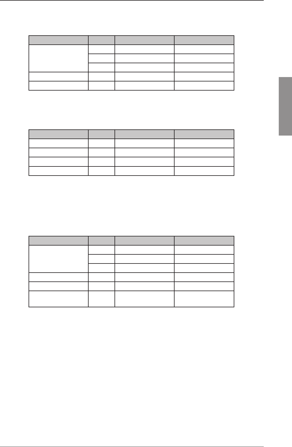
Power consumption:
Rx Mode: Approximately
45W 150 W 250 W 500 W
Tx, SSB speech 175 W 300 W 600 W
Tx, SSB two-tone 300 W 550 W 1100 W
Tx, DSC/TELEX 310 W 600 W 1000 W
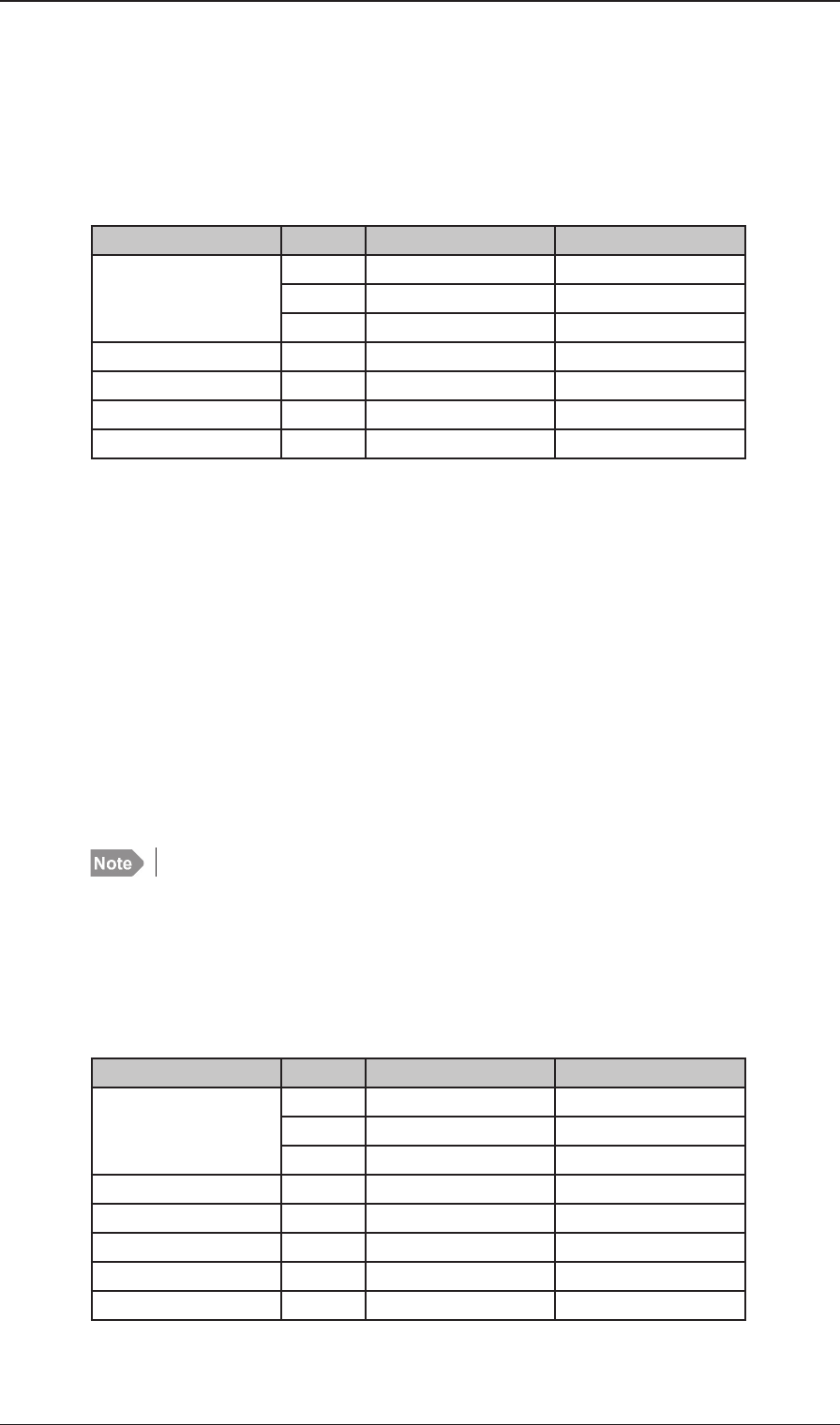
Compass safe distance:
Compass safe distance in accordance with ISO/R 694 are given below in metres
Unit Standard
5.4°/H
Steering
18°/H
Control Unit 1.2 0.5
Transceiver Unit 0.85 0.25
Antenna Tuning Unit 0.6 0.3
Handset0.3 0.2
Cradle 1.1 0.7
Loudspeaker 2.2 1.6
IP ratings (estimated):
System Transceiver Unit Antenna Tuner
Unit * Control Unit
150 W IP43 IP56 IP54
250 W IP43 IP56 IP54
500 W IP20 IP56 IP54
* Antenna cable must be carefl ly installed to obtain this IP rating
Dissipated heat: The dissipated heat in standby RX mode is typically 45 W depending on
attached ancillary equipment.
In transmit mode, use the consumption fi gures for the appropriate mode,
multiplied by 0.66.
E.g. 0.66 x 175 W = 115.5 W dissipated heat for a 150 W system in SSB
speech mode.
For a fi gure in kilocalories (kcal), multiply dissipation effect by on-time in
hous and then by 0.860.
For the 150W system, e.g. 115.5 W x 2 h + 45 W x 22 h (TX 2 hours + RX
22 hours a day) = 1221 Wh. 1221 Wh x 0.860 ~ 1050 kcal a day.
1.2.2 Receiver characteristics
General: Complies with ETSI 300373 in the ITU marine bands.
Frequency range: 150 KHz to 30 MHz
Frequency resolution: 100 Hz by keyboard entry
10 Hz, 100 Hz or 1 KHz search/fi ne-tune facility is provided
Chapter 1: General information 1-3
General information
98-144591-A
Technical data
Input impedance: Rx : 50 ohm
12V DC / 20 mA is available for possible use of active antenna.
Sensitivity: Telephony (J3E): below 11 dBμV for 20 dB Sinad
Broadcast (A3E): below 25 dBμV for 20 dB Sinad
DSC/Telex (J2B): below 0 dBμV
Intermodulation:
Wanted signal Signal
Telephony (J3E) 30 dBμV
Intermodulation level above 80 dBμV
Telex (J2B) 30 dBμV
Intermodulation level above 90 dBμV
DSC (J2B) 20 dBμV
Intermodulation level above 80 dBμV
Spurious rejection: Signal: above 70 dB
Audio output power: Build-in loudspeaker 6 W typical.
Optional loudspeaker output 6 W typical with less than 10 % distortion.
Output intended for 8 ohm loudspeaker.
1.2.3 Transmitter characteristics
General: Complies with ETSI 300373 and FCC in the ITU marine bands.
The Transmitter characteristics are with the Antenna Tuning Unit included.
Frequency range: All frequencies in the range 1605 KHz to 30 MHz however by factory
default arranged in the ITU marine bands.
Factory pre-programmed:
Band Frequency
00 1.605 - 4.000 MHz
01 4.000 - 4.438 MHz
02 6.200 - 6.525 MHz
03 8.100 - 8.815 MHz
04 2.230 - 13.200 MHz
05 6.360 - 17.410 MHz
06 8.780 - 18.900 MHz
07 19.680 - 19.800 MHz
08 22.000 - 22.855 MHz
09 25.070 - 25.210 MHz
10 26.100 - 26.175 MHz
Frequency resolution: 100 Hz
Output impedance: TX: 50 ohm
The Antenna is matched by the Antenna Tuning Unit
Power reduction: Low power: 20 W PEP
Intermodulation: below -31 dB/PEP

1-4 Chapter 1: General information 98-144591-A
Technical data
Spurious Emission: below -43 dB/PEP
below -60 dB/PEP (FCC)
Hum and noise: Less than - 40 dB/PEP
Output power 150 W SSB: ± 1.4 dB into 50 ohm Antenna.
DSC/Telex:
85 W ± 1.4 dB
Output power 250 WSSB: ± 1.4 dB into 50 ohm Antenna.
DSC/Telex:
125 W ± 1.4 dB
Output power 500W SSB: 1.6-4 MHz 400 W PEP +0/-1.4 dB
4-27 MHz 500 W PEP ±1.4 dB into 50 ohm Antenna.
DSC/Telex:
250 W ± 1.4 dB
1.2.4 DSC Watch keeping receiver characteristics
General: Complies with ETSI 300338 and ETSI 301033..
Frequency range: Default set to D1 - 2187.5 KHz.
When scanning is enabled by option code it will default be D6 - 2-4-6-8-
12-16 MHz.
Can be reduced to minimum 3 frequencies via the Service Interface.
Input impedance: DSC/Telex: 50 ohm
12V DC / 60 mA is available for use of active antenna.
Sensitivity: DSC (J2B): below 0 dBμV
Intermodulation: DSC (J2B): Wanted Signal: 20 dBμV
Intermod. level: above 70 dBμV
Spurious rejection: above 70 dB
1.2.5 Antenna Tuning Unit characteristics
Frequency range: 1.6 MHz - 27.5 MHz
Antenna requirements: 8-18 m wire and/or whip antenna
Antenna tuning: Fully automatic with no presetting
Tuning speed: 0.1 - 8 sec. (typical)
Power capability
150 W/250 W: 350 W PEP into 50 ohm antenna
500 W: 600 W PEP into 50 ohm antenna
Extreme operating
temperature: from -25°C to +55°C

Chapter 1: General information 1-5
General information
98-144591-A
Technical data
1.2.6 DSC/Telex modem characteristics
DSC: DSC Equipment class: Class A
Protocols: ITU-R M. 493-13
Ship’s identity: 9-digit identity number
NMEA interface: According to IEC 61162-1
GLL, RMC, ZDA, GGA, GNS
TELEX: Protocols: ARQ, FEC and Selective FEC
Ship’s identity: 5- and/or 9-digit identity number
1.2.7 Dimensions and weight
Control Unit
6301/02/03: Width: 241 mm (9.5")
Height: 107 mm (4.2")
Depth: 99 mm (3.9")
Weight: 0.82 kg (1.8 lbs)
Transceiver Unit 150 W/250 W
6365/66/68: Width: 390 mm (15.3")
Height: 445 mm (17.5")
Depth: 127 mm (5")
Weight: 19 kg (41.9 lbs)
Transceiver Unit 500 W
6369: Width: 392 mm (15.4")
Height: 507 mm (20")
Depth: 217 mm (8.5")
Weight: 28 kg (61.7 lbs)
Antenna Tuning Unit 150 W/250 W
6384: Width: 290 mm (11.4")
Height: 500 mm (19.7")
Depth: 80 mm (3.1")
Weight: 3.3 kg (7.3 lbs)
Antenna Tuning Unit 500 W
6383: Width: 401 mm (15.8")
Height: 617 mm (24.3")
Depth: 356 mm (14")
Weight: 17 kg (7.3 lbs)
Equipment category: Control Unit: Protected
Transceiver Unit: Protected
Antenna Tuning Unit: Exposed
(According to IEC60940)

1-6 Chapter 1: General information 98-144591-A
Technical data
2-1
Installation
Chapter 2: Installation
98-144591-A
Mounting the Units
Installation
2.1 Description
Correct installation of the equipment is important for maximum performance and reliability. Antennas
and earth connections must be installed with the greatest care using corrosion resistant materials.
Cable routing shall be made so that the cables are protected from physical damage. Sharp cable bends
especially on coaxial cables must be avoided and a suffi cient number of clips or straps should be used
to secure the cables.
2.2 Mounting the units
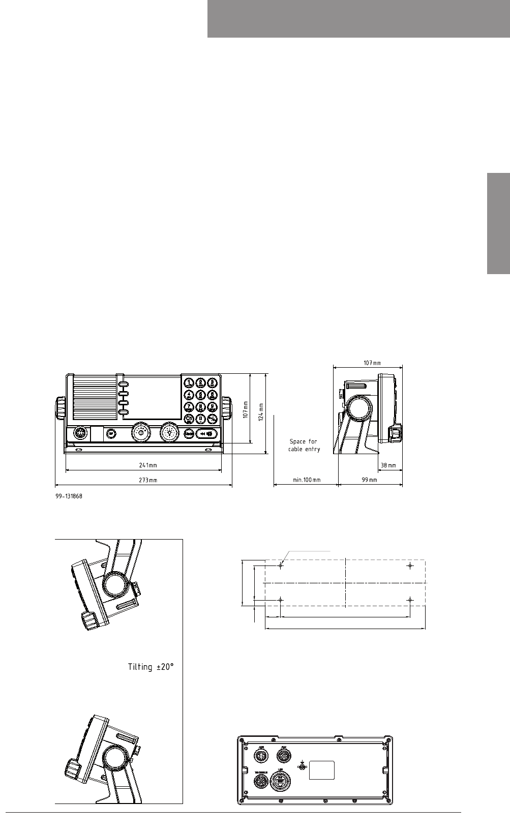
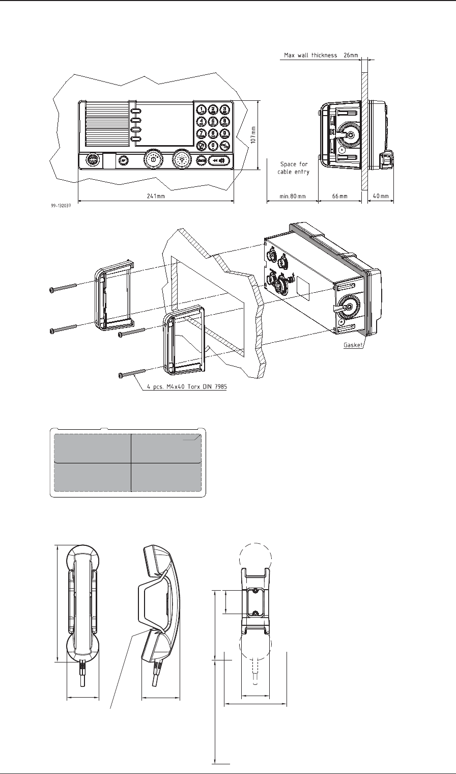
2.2.1 Mounting the Control Unit (CU)
One Control Unit can be connected to the Transceiver Unit using the cable supplied (CU-TU Bus). The CU
may be mounted up to 100 m from the Transceiver Unit using just a multicable 5 x 2 x 0.5 mm2 screened.
The Control Unit may be tabletop or bulkhead mounted.
Control Units with mounting bracket
Mounting option Drilling plan for bracket
Chapter 2
Control unit connector panel
Weight:
Control Unit 0.82 kg
Mounting Bracket 0.20 kg
200mm
53mm
71mm
247mm
9mm
4 x M4 or hole for
self-tapping ø3.9
23.5mm
2-2 Chapter 2: Installation 98-144591-A
Mounting the Units
Control Units with fl ush mounting bracket
Drilling plan
Flush mount template
Remove material from shaded area only!
89mm
227mm
R2.5mm x 4
Weight:
Flush mount bracket 0.04 kg
WARNING:
Only use screws supplied with
mounting kit for attaching fl ush
mounting bracket to Control Unit.
Handset for Control Unit
This Handset has a hook-on/off function,
which is activated by a small magnet embedded
in the cradle.
The cradle must be installed as illustrated in
order to ensure the hook-on/off functionality
of the Handset.
75
62
226
* 120
min. 100
Space for handset access
Space for cable and handset cable
54
45
135
39655C
Drilling plan
Weight:
Handset for Control Unit 0.4 kg (0.02
lbs)
Dimensions are in mm
2-3
Installation
Chapter 2: Installation
98-144591-A
Mounting the Units
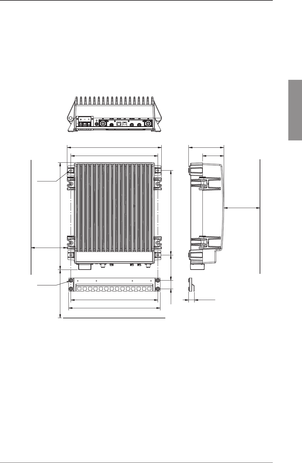
2.2.2 Mounting the Transceiver Unit (TU)
The Transceiver Unit should be installed in a dry place and consideration should be given to acces-
sibility for servicing. It is important to provide suffi cient airspace below, above and in front of the unit
for adequate air circulation through the cooling fi ns. The drawing below shows the outer dimensions,
mounting possibilities and the minimum distance to other objects, as well as a drilling plan.
Transceiver Unit 150 W/250 W
105 mm 350 mm
360 mm
391 mm
35 mm
150 mmMin.
379 mm
150 mmMin.
360 mm
Space for
cable access
Space for
service
4 x ø8mm
443 mm
4 x ø6mm
23.5 mm
88 mm
145 mm
500Min. mm
Space for airflow
and service
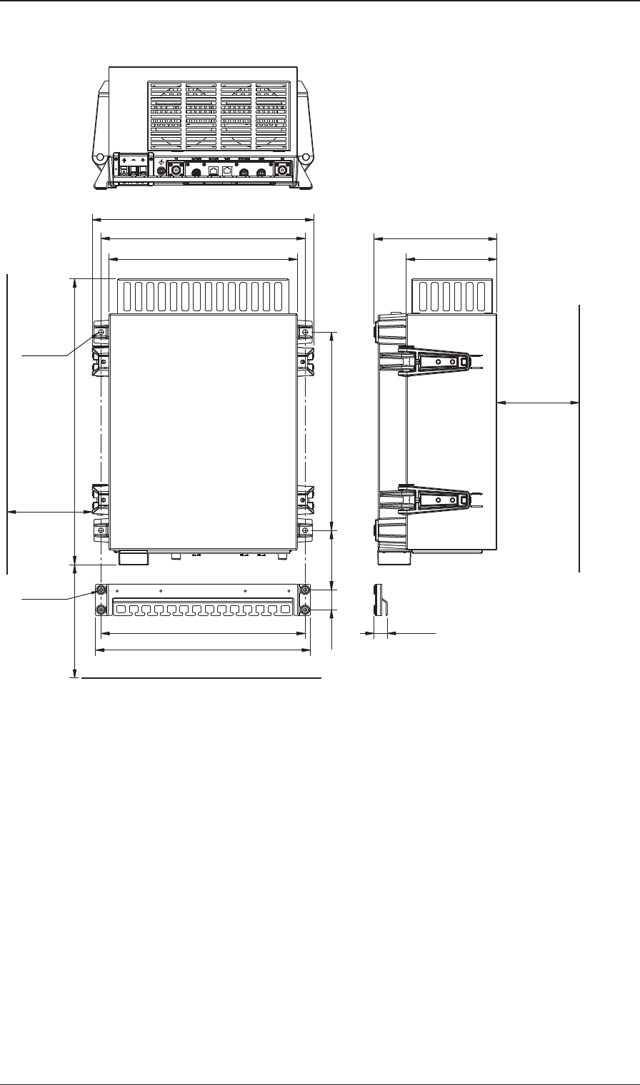
2-4 Chapter 2: Installation 98-144591-A
Mounting the Units
Transceiver Unit 500 W
360 mm
379 mm
35 mm 105 mm 350 mm
150 mmMin.
200 mmMin.
360 mm
391 mm
332 mm
505 mm
Space for cable
and airflow
Space for
service access
Cable fitting
4 x ø8mm
4 x ø6mm
1000Min. mm
160 mm
217 mm
23.5 mm
Space for airflow
and service
2-5
Installation
Chapter 2: Installation
98-144591-A
Mounting the Units
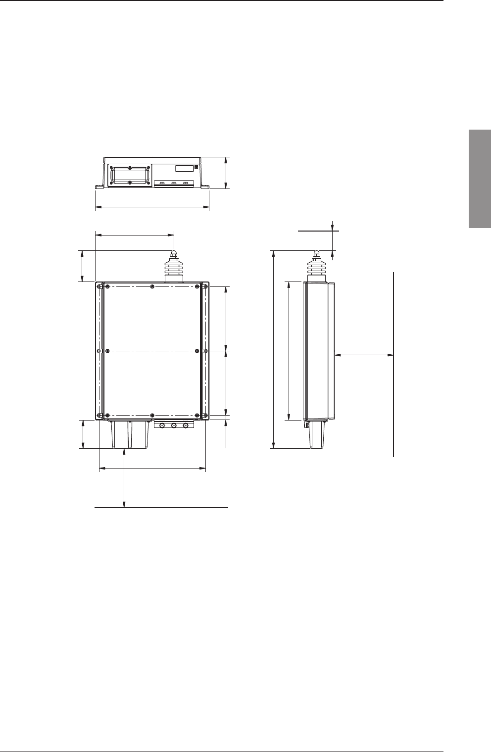
2.2.3 Mounting the Antenna Tuning Unit (ATU)
The ATU may be mounted up to 100 metres from the Transceiver Unit using just one RG-213/U or
better coaxial cable.
The ATU must be installed outside in a convenient position to have good access for suffi cient length
of feeder wire to meet the antenna connection point.
Antenna Tuning Unit 150 W/250 W
It is recommended to use the mounting bracket shown in section 2.2.4
Space for cable and
service access
164 mm 164 mm
271 mm
150Min. mm
75 mm
12 mm
80 mm
200 mm
352 mm
504 mm
500Min. mm
50Min. mm
Space for
service access
Space to nearest overhang
80 mm
290 mm
2-6 Chapter 2: Installation 98-144591-A
Mounting the Units
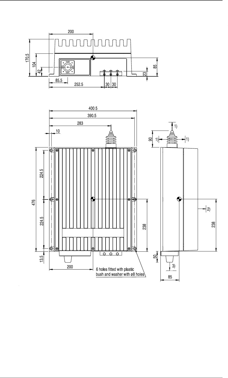
Antenna Tuning Unit 500 W
1) Distance to metal constructions: min. 150
2) Space for service access: min. 500
3) Space for cable and service access: min. 200
Dimensions are in mm
Tolerance: +/- 1 mm
Mounting hole: ø8
Weight: 17 Kg
4-0-32426
2-7
Installation
Chapter 2: Installation
98-144591-A
Mounting the Units
2.2.4 Recommended ATU installation
On a metal-hull vessel
Install the ATU on an ATU Mounting Kit. The kit is stainless steel which can be bolted or welded to ship's
hull to ensure good and solid connection in the radio system primary ground point.
The mounting kit will at the same time ensure straight and fl at mounting for the ATU cabinet and provide
good airfl ow around the ATU for better heat dissipation.
On a wooden or fi breglass hull vessel
Install the ATU on an ATU Mounting Kit. The kit is stainless steel which can be bolted to ship's hull
and then provide a ground plane connection to ensure good and solid connection in the radio system
primary ground point.
The ground plane should normally be provided in as wide surface as possible with shortest possible
connection to ships earth connection to the water surface.
Alternatively and in case of long ground connections the grounding should be arranged in a solid and
shielded cable connection where suffi cient cable square material to provide the connection and the
shielding connected to ATU Mounting Kit and left open at earth connection side.
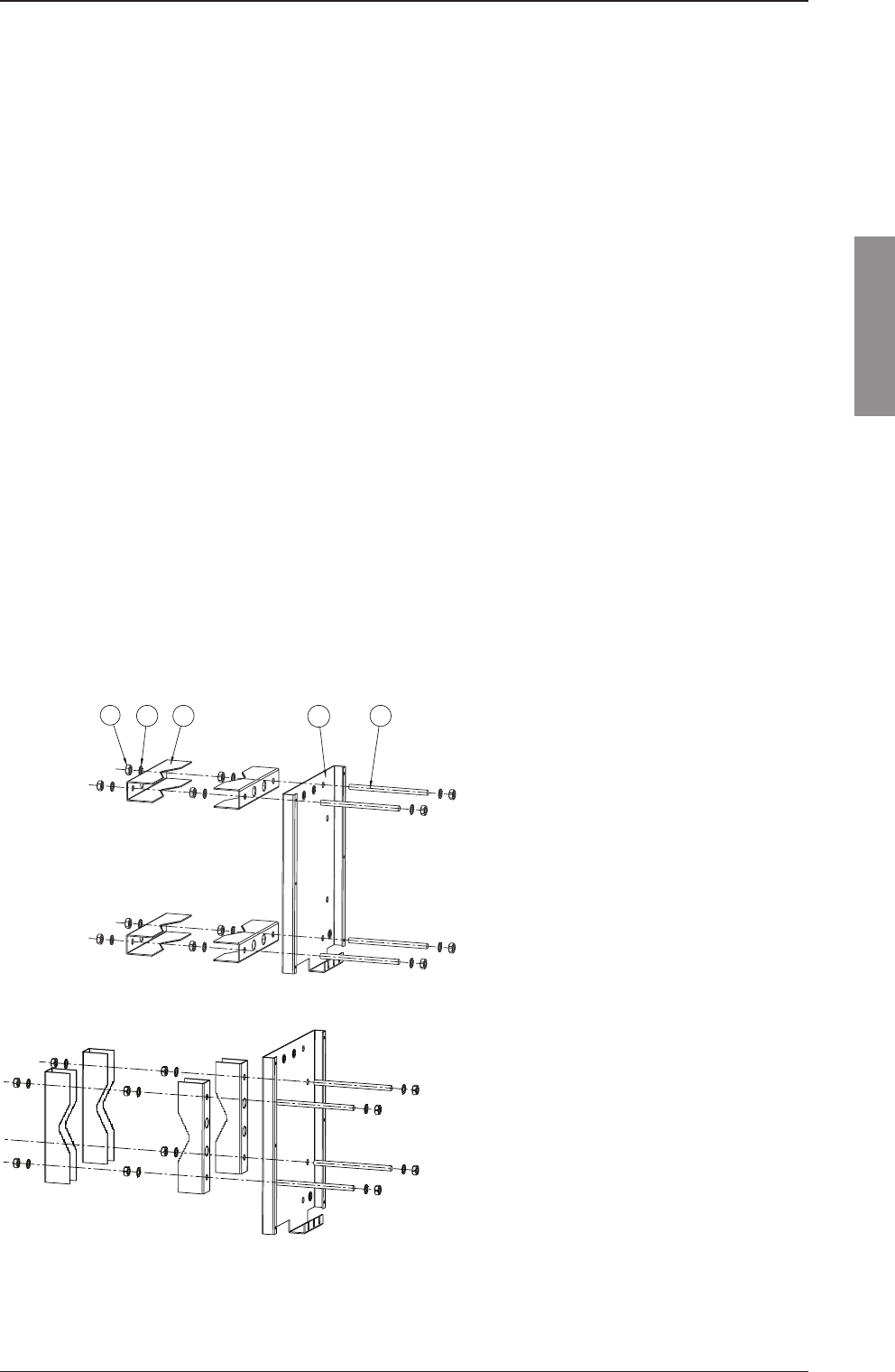
ATU Mounting Kit
An optional ATU Mounting Kit as shown below is available in two versions:
1. Comprises of mounting plate and fi ttings for mast - part no. 737589
For mounting the ATU directly on a mast, where the Mounting Plate and fi ttings for mast can form a
suffi cient earth connection on a steel mast welded to the superstructure.
2. Comprises of the mounting plate only - part no. 737588
To get an even mounting surface on an uneven support.
13 5
4
2
1. Nut M10
2. Tooth lock washer M10
3. Fitting for mast
4. Mountingplate for ATU
5. Treadrod M10
2-8 Chapter 2: Installation 98-144591-A
Ground connections
2.2.5 SAILOR 6208 Control Unit Connection Box
The SAILOR 6208 is used to convert the small cable dimension from preconfi gured cable plug to spring
loaded terminals with strain relief for connection to larger cable dimensions.
The box is used to connect the Transceiver Unit to Control Units and Message Terminal respectively.
The box is fi tted with optional 120 ohm CAN-BUS termination.
Weight:
SAILOR 6208 0.5 kg.
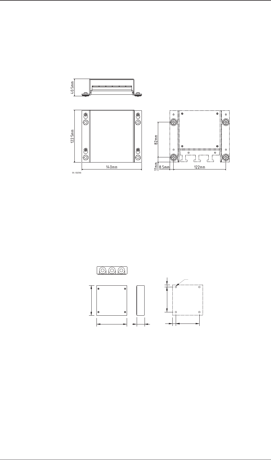
2.2.6 SAILOR 6209 Accessory Connection Box
The SAILOR 6209 is used to convert the small cable dimension from LTW plug to screw terminals with
strain relief for connection larger cable dimensions.
The box is used to connect the Transceiver Unit and /or the Control Unit to peripheral equipment e.g.
GPS, external loudspeaker etc.
4 pcs. ø5.50
100
100
26 11.00 77.70
7.50
82.70
36998
Weight:
SAILOR 6209 0.4 kg.
Dimensions are in mm
The SAILOR 6208 and the SAILOR 6209 may be ordered as accessory. Please fi nd accessory list on the
last page of this manual.
Drilling Plan
Drilling Plan
2-9
Installation
Chapter 2: Installation
98-144591-A
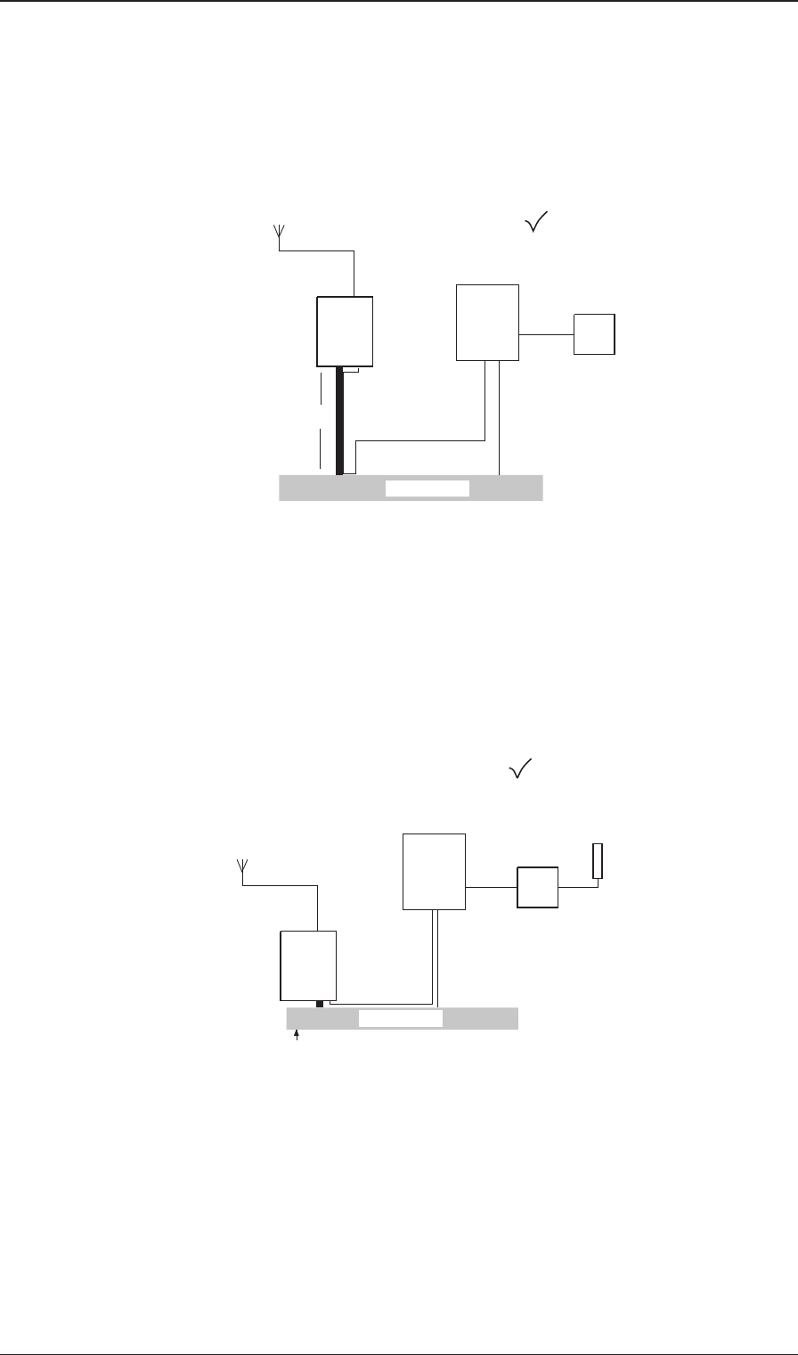
Grounding considerations
2.3 Ground connections
2.3.1 Grounding considerations
Proper system grounding is one of the most important installation details.
Two areas of grounding must be considered:
a) The ground connection between the ATU and earth plane.
b) The ground connection of the TU and the externally connected equipment.
Each area requires separate considerations even though they are interrelated. Ideally the Control Unit,
Transceiver Unit, Antenna Tuning Unit and the antenna ground-plane must have the same RF ground
potential. Unfortunately this situation is seldomly achieved, but interference problems will be reduced
along with how close to this “ideal” the grounding of the installation is performed.
On some installations ground loops will cause problems. A ground loop is caused by more than one
ground path for a given unit. This will introduce circulating RF currents which may cause malfunction
of other equipment onboard the ship as well as a “hot” handset.
ATU
TU
CU
'Hot' Handset
RF current loop
Ground-Plane
Not OK installation
Zg
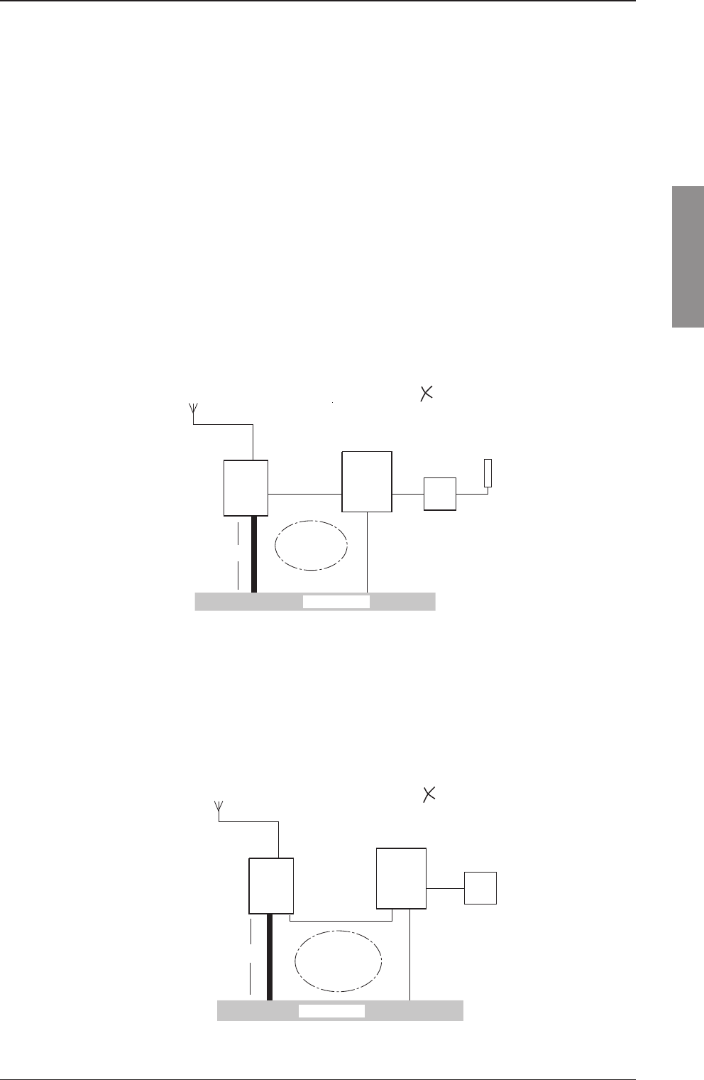
2.3.2 RF ground loop
It is not always possible or practical to mount the ATU using a very short strap to the actual ground-
plane. In such a case the coaxialcable may be connected between units with different ground potentials
causing RF loop-current to fl ow.
ATU
TU
CU
Not OK installation
coaxial cable
RF current loop
Ground-Plane
Zg
Vg = Iant x Zg
2-10 Chapter 2: Installation 98-144591-A
Grounding considerations
2.3.3 Minimizing ground loops
By routing the coax cable very close together with the ATU ground strap (secure good RF coupling
between the two) all the way down to the ground-plane, there will be no RF ground loop left to generate
the interference.
ATU
TU
CU
coaxial cable
Ground-Plane
OK installation
Zg
Vg = Iant x Zg
2.3.4 Antenna start
The vertical antenna always starts at its electrical ground-plane, whether or not it is physically mounted
there. First determine the antenna’s electrical ground-plane, which is where the ATU must be mounted.
Where possible always take the ATU to the ground, not the ground to the ATU.
In case of a fi breglass boat, the ground-plane may well be at the hull grounding terminal. Then this is
where the Antenna Tuning Unit should go and this is where the antenna actually starts.
ATU
TU
CU
OK installation
Not a 'Hot' Handset
Ground-Plane
The antenna starts here
2-11
Installation
Chapter 2: Installation
98-144591-A
2.3.5 Antenna Tuning Unit
As the earth connection of a transmitter is a very im-
portant part of the antenna system, it is of the
utmost importance to keep in mind that the earth con-
nection of the Antenna Tuning Unit must
have the lowest possible RF-impedance. Losses in the
earth connection will result in a decrease in
radiated power which means that the range of the
transmitter will be reduced. In steel ships a 100 x
0.5 mm copper strap as short as possible is connected
between the earth terminal at the bottom
of the Antenna Tuning Unit and two or three 1/2" or
M12 bolts welded to the superstructure.
It is recommended to install the ATU by means of the
ATU mounting bracket shown in section 2.2.4 as this
stainless steel bracket can be welded into the super
structure and will provide the best possible none cor-
roding connection.
Vessels constructed of non-conducting materials must be equipped with a copper earth plate having a
minimum area of 1 square metre mounted below the water line. From a copper earth bolt hard soldered
to the earth plate a 100 x 0.5 mm copper strap is run, preferably uninterrupted to the earth terminal at
the bottom of the Antenna Tuning Unit.
Should it be necessary to break the copper strap, for example to pass through a deck, two or three 1/2"
or M12 bolts should be used for this feed through.
On wooden ships having a superstructure of metal,
this superstructure should also be effectively con-
nected to the copper strap by using stainless steel
bolts and preferably pieces of stainless steel strips
between the metal parts.
On fi bre glass boats, such as yachts and sailing boats,
it may be diffi cult to install a suffi ciently good earth.
Short copper straps are bolted to conducting parts
on the engine, the keel and other conducting objects.
Many copper straps can be glued to the inner surface
of the hull below the water line to produce a large
capacitance to the water.
It is important that the total area of copper is large
and that the distance between the copper surface and
the water is as small as possible. The copper straps
are connected directly to the ATU.
On ships where the environmental conditions re-
quire shielded grounding downlead in order to avoid
radiation from same downlead, it is recommended
to use a shielded cable with a non-stranded wire
having adequate wire dimension to secure the proper
grounding. Cable shielding should be connected the
earth terminal at the bottom of the Antenna Tuning
Unit and left open at the earth connection side.
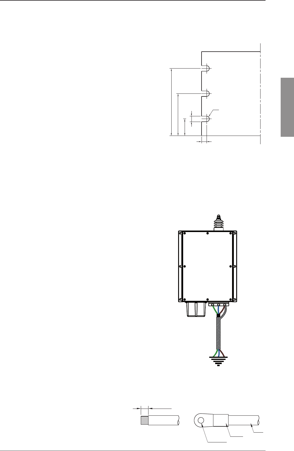
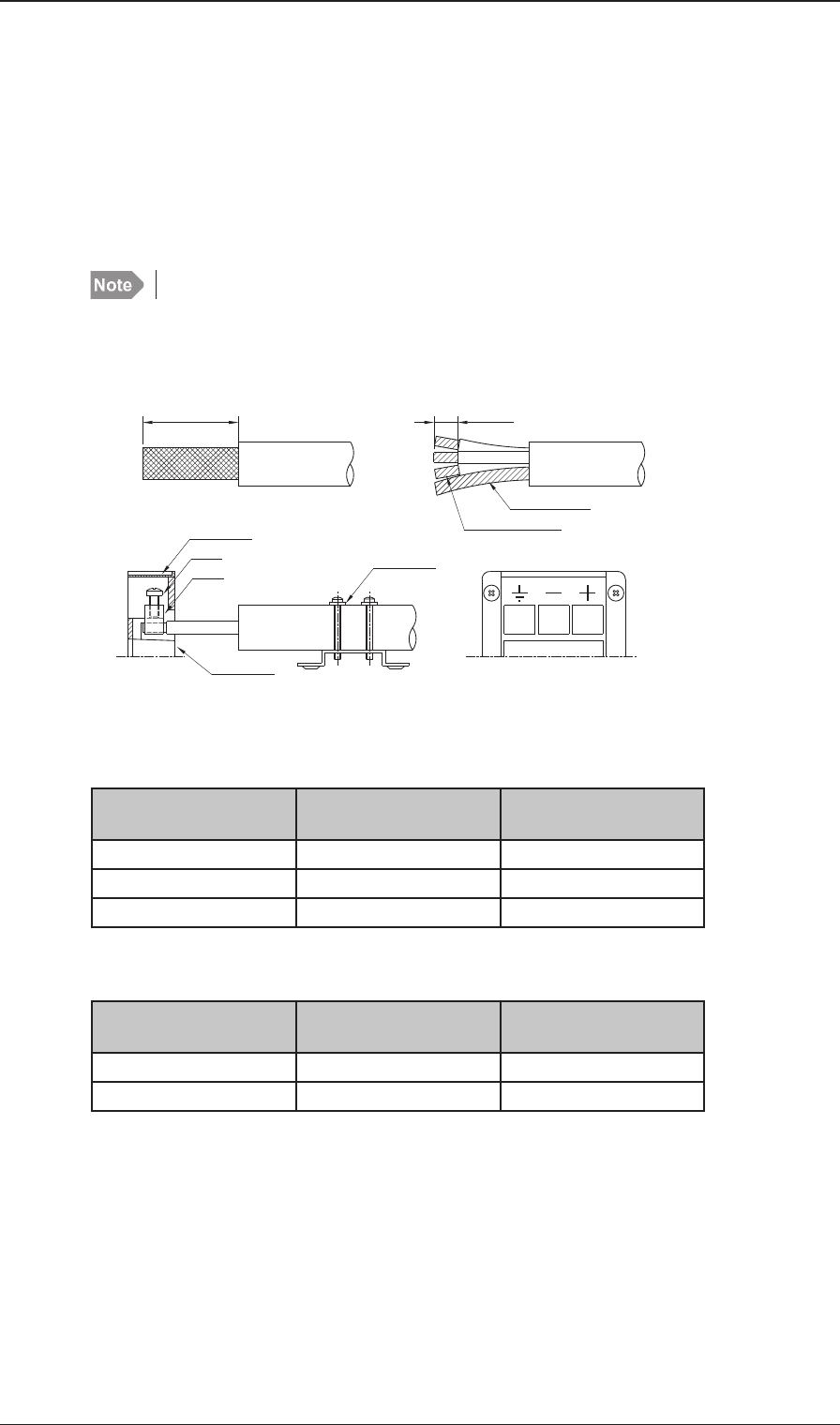
2.3.6 Transceiver Unit and Control Unit
The Transceiver Unit is preferably grounded
separately to the ships metal in the shortest
possible way. A 10mm² (AWG 7) to 16mm²
(AWG 5) ground wire is connected to the
ground terminal (cable clamp) at the bot-
tom of the unit.
Antennas
11mm
ø5.4mm
crimp
wire
Shielded ground downlead
Copper strap 100 x 0.5mm
Dimensions are in mm.
37872
20
50
80
6
6.6
R3.3
Copper strap cut-out at the ATU end
2-12 Chapter 2: Installation 98-144591-A
Antennas
2.4 Antennas
2.4.1 Transceiver Antenna
The equipment is used with separate transmitting and receiving antennas. The antennas should be
erected in the open, away from conducting object such as derricks etc. which may cause reduction of
the radiated power. Insulators should be of the best type having low leakage even when wet. Stays,
wires, steel masts etc. should be either effectively earthed or insulated. The antenna should also be kept
as far away as possible from electrical equipment in order to minimize noise. Electrical installation such
as cable braiding (screens) and instruments in the vicinity of the antenna should be earthed effectively,
and the instruments in question should be fi tted with noise-interference suppression devices, effective
in the range 0.1 MHz to 30 MHz to avoid malfunction of these instruments. The Antenna Tuning Unit
will tune on any frequency in the range 1.6 to 27 MHz to good whip and/or wire installations of 12 to
18 m total electrical length.
Shorter antennas, electrical length down to 8 m can be used. Where possible long antennas should be
installed to maximize the radiated power in the lower frequency bands.
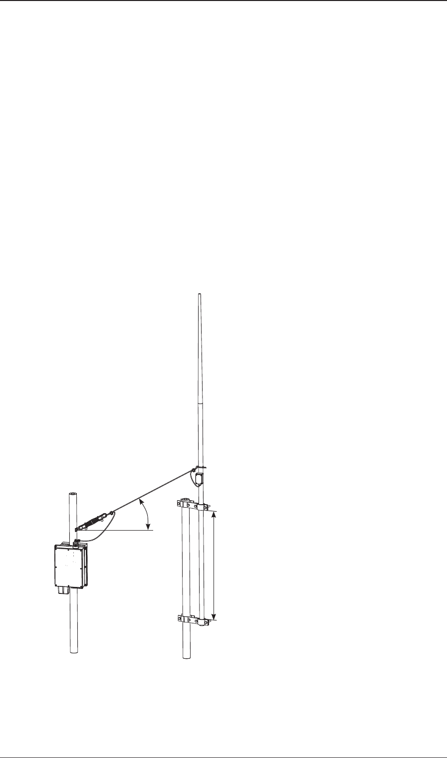
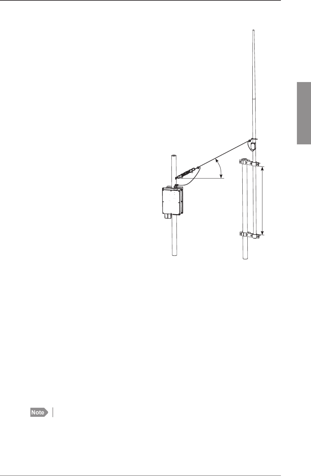
In general a 12 m antenna installation can be made using an 8 metres whip and 4.5 m feeder or a 10 m
whip and 2.5 m feeder. In both cases the whip should be mounted on a pole allowing for the feeder to be
erected at an angle of no less than 60 degrees
to create a vertical antenna system. Using
horizontal feeders or feeders mounted at an
angle below 45 degrees usually transform the
antenna radiation resistance to a lower value
reducing the radiated power. Furthermore,
the total antenna system should be kept well
away from conductive objects such as the
mast. Usually a horizontal distance of more
than 4 metres will create good results.
The antenna is terminated at the insulator at
the top of the Antenna Tuning Unit. The insula-
tor must be relieved from mechanical stress
by using max. 1 meter fl exible wire between
the insulator and a support. To maximize the
radiated power and avoid fl ash over keep
distance to metal parts as long as possible.
All wire junctions in the antenna system
must be made with cable lugs of correct size
according to the wire gauge. This will prevent
bad connections due to corrosion. For further
corrosion proofi ng grease may be applied to
the cable joints.
>45°
>1 meter
2-13
Installation
Chapter 2: Installation
98-144591-A
Antennas
2.4.2 Considerations on antenna length requirements
Antenna impedance
The length of the transmitting antenna used with MF/HF equipment in general and the MF/HF equip-
ment specifi cally for purpose of this discussion is of utmost importance for the proper performance of
the equipment, i.e. the ability to tune properly to the antenna and the effective transmission range. In
terms of transmission range, more important than increasing the transmitter RF output power from say
150 W to 250 W is in fact the use of an adequate length antenna.
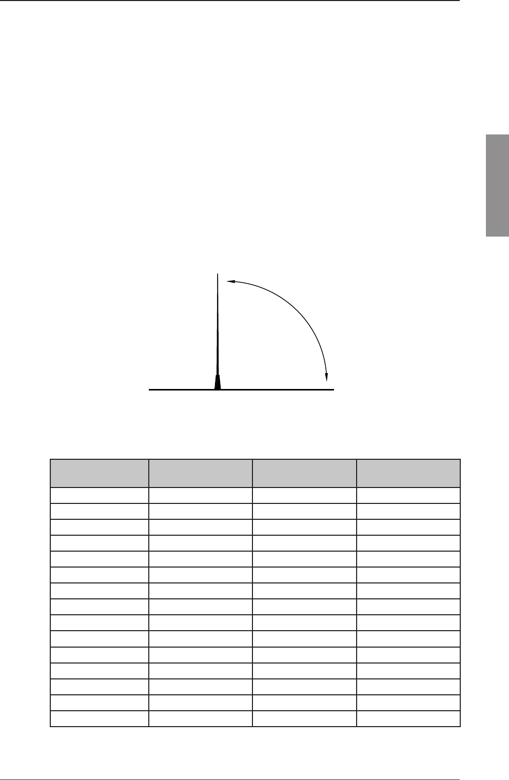
Comparatively, any practical length whip antenna remains by far too short for the wavelength for which
it is used, especially at the lower frequencies. For the frequency range 1.6 – 30 MHz defi ning the com-
mercial MF/HF marine band, the wavelength spans the range 190 – 10 m approximately.
A proper ground plane for the transmitting antenna is essential in order for this to effectively radiate
power into the air. When applying RF energy to the whip antenna, the presence of the ground plane
creates capacitance between the whip antenna and the ground plane. This capacitance will vary with
frequency, hence, the impedance of the whip antenna as seen from the transmitter will vary with the
frequency range over which the transmitter is operated.
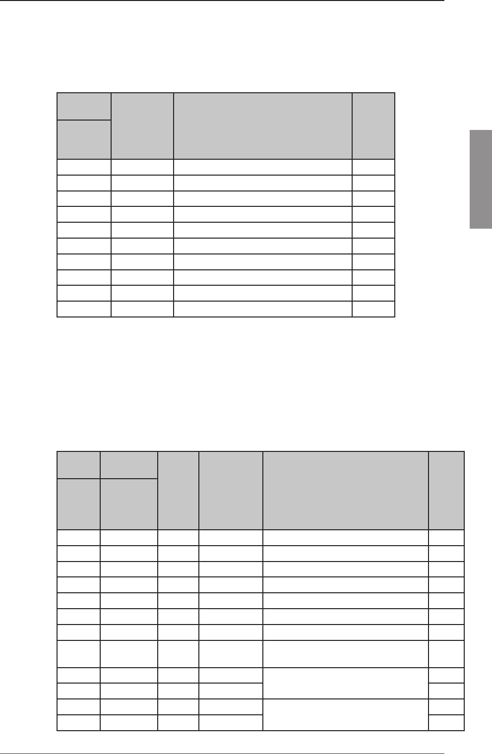
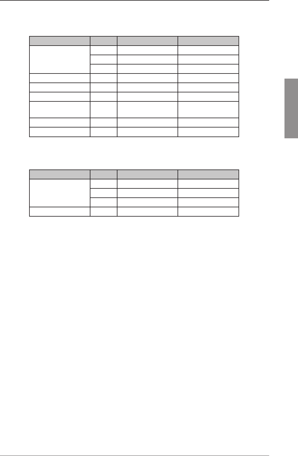
As an illustration of the impedance variation with frequency of a transmitting antenna refer to below
table listing the impedance as measured on a 6, 7 and 8 m whip antenna respectively with a 2 m feed line.
Frequency
(MHz)
Transmitting Antenna
6 m
Transmitting Antenna
7 m
Transmitting Antenna
8 m
1.6 3-j1.310 3-j1.200 4-j1.060
2.0 4-j1.025 4-j970 5-j800
3.0 7-j970 8-j550 9-j470
4.0 9-j410 10-j325 11-j250
5.0 17-j260 18-j200 20-j145
6.0 20-j150 25-j95 28-j38
7.0 35-j65 40-j10 55+j55
8.0 40+j30 50+j90 60+j155
10.0 100+j190 130+j270 200+j400
12.0 600+j450 650+j450 1000+j300
16.0 1000+j200 900-j500 500-j500
18.0 700-j500 400-j500 250-j450
22.0 200-j400 90-j280 70-j80
25.0 90-j195 75-j10 240-j200
30.0 200+j150 500+j0 400-j300
In the fi gures for the impedance in this table the imaginary part (jxxx) describes the value of capaci-
tance part.
Ground plane
Capacity is
created when
RF energy is
applied to
aerial
Whip antenna

2-14 Chapter 2: Installation 98-144591-A
Antennas
Function of the Antenna Tuning Unit (ATU)
The MF/HF transmitter power amplifi er (PA) provides a fi xed output impedance of 50 ohms over its
operating frequency range to which the load (the antenna) should be matched (i.e. load should prefer-
ably be 50 ohms also) in order for the transmitter to deliver its full power output to the load. However,
with the varying impedance of an antenna, as described above such a condition may only be met at
one or - at best - a few specifi c frequencies. On the remaining frequencies within the transmission band
the varying mismatch between the transmitter fi xed output impedance and the different impedance of
the antenna at any given frequency will result in reduced RF power delivered to the antenna – in worst
case hardly any power at all - if the antenna was connected directly to the transmitter.
To overcome the frequency dependant mismatch between the transmitter output impedance and the
antenna (load) impedance, the ATU is put into the antenna circuit to provide variable compensation
counteracting the varying impedance of the antenna, the end result of which is the “transformation” of
this into a “fi xed” app. 50ohms load, as “seen” by the transmitter.
The compensation is achieved mainly through the introduction of an induction in series with the antenna
circuit, the value of which will create a resonance circuit at the given frequency. Hence, depending on
the impedance of the antenna (i.e. the transmission frequency) a suitable combination of inductors from
a bank of inductors in the ATU, are selected through of a number of relays, the activation of which is
controlled by the ATU processor during the tuning process.
MF/HF ATU
For the impedance of e.g. an 8 metres transmitting antenna of 5-j800 ohms at 2 MHz, as stated by the
manufacturer, the ATU will easily tune to the impedance of this antenna system - in fact, the array of
coils in the ATU tuning circuitry allows tuning all the way down to the impedance of 4-j1060 ohms of
this antenna system at 1.6 MHz. A slightly shorter antenna system might be used at the possible sacrifi ce
of the ability to tune at the extreme low end of the frequency band below 2 MHz.
However the impedance of the antenna system is, infl uenced by any nearby metallic objects such as
the vessel's superstructure and/or nearby metal poles/masts or stays/wires. Consequently, in order not
to alter the impedance of the antenna system which may eventually cause diffi culties for the ATU to
match the resulting impedance, the transmitting antenna should be kept at a distance of no less than
4 m from any such objects. Similarly goes for the feed wire connecting the ATU to the antenna which
should be kept at a minimum of 1 m from metallic objects.
It should be noted that even though the ATU will tune to the mentioned antenna system length, the ef-
fective radiated power (i.e. the effi ciency of the antenna) in the low frequency end will suffer compared
to longer antenna systems of recommended electrical length 10-18 m.
2-15
Installation
Chapter 2: Installation
98-144591-A
Antenna system installation in practice
As noted on the impedance fi gures in above table,
the measurements were made with the antenna
raised on a 2 m steel pipe over a fl at steel roof
(ground plane) and a 2 m feed line. This implies
that the measured impedance is in fact that of the
actual antenna (electrical) length plus additional 2
m. The electrical length of the 8 m bracket mount
(side fed) Comrod transmitter antenna is 6.8 m
resulting in a total electrical length of the antenna
system of 8.8 m.
Electrical specifi cations transmitting antennas
The connection to the transmitting antenna is by a
single ended wire - the feed line - connecting from
the ATU top connector. This feed line adds to the
electrical length of the antenna (when correctly
installed), thus in effect increasing the effi ciency
of the antenna. The longer the feed line the better
the effi ciency of the antenna system consisting of
transmitting antenna and the feed line.
For direct addition of feed line length to antenna
electrical length the feed line should be vertically
installed as an extension downwards of the transmit-
ting antenna. In practice, where the ATU must be
placed between the feed line and the ground plane
(steel deck), the direct vertical installation of the
feed wire may be diffi cult in terms of total height.
This may partly be accounted for by allowing the
feed wire installed at an angle of at least 45 degrees
towards the horizontal plane. Installing the feed wire
at lower angles will create capacitance to the ground
plane decreasing the effi ciency of the antenna.
2.4.3 Receiver antenna
The receiver antenna may be an active or a passive type.
The antenna should be erected well in the clear and kept away as far as possible from electrical equip-
ment in order to minimize noise. Electrical installation such as cable braiding and instruments in the
vicinity of the antenna should be earthed effectively, and the instruments in question should be fi tted
with noise-interference suppression devices, effective in the range 0.1 to 30 MHz. The antenna feed-in
should be coaxial cable.
In case of a passive antenna the feed-in should be as short as possible, especially in the case of short
antennas. The recommended antenna length is 7-30 meters. If a long coax cable is necessary an im-
pedance matching transformer should be inserted at the antenna or an active antenna should be used.
DC supply voltage for an active antenna is available at the RX antenna connector after switching is on
in service interface. The supply voltage is +12 V (60 mA). The RX port is short circuit protected.
The receiver antenna should be mounted as far from the transmitter antenna as possible - recommended
minimum 6 metres.
For active RX antennas, it is recommended to choose a physical length ≥1 meter.
Antennas
>45°
>1 meter
2-16 Chapter 2: Installation 98-144591-A
Antennas
2.5 DC Power cabling
The supply leads are connected to the supply terminal of the Transceiver Unit. The supply terminal is
designed for 3 wire shielded power supply cable to meet international installation and EMC requirements.
The safety ground wire is connected to the terminal showing ground symbol and shielding connected
to the cable fi tting shown in page 2-3 must be well grounded to ships hull.
The earth connection of the equipment will not cause the battery to be earthed. Maximum permissible
peak voltage between the battery terminals and earth is 100 V.
Fusing must be provided in the supply leads for cable protection.
Cable lengths stated in tables are the total cable length from battery terminals via charger, shunt box,
DC distribution to TU DC-terminals.
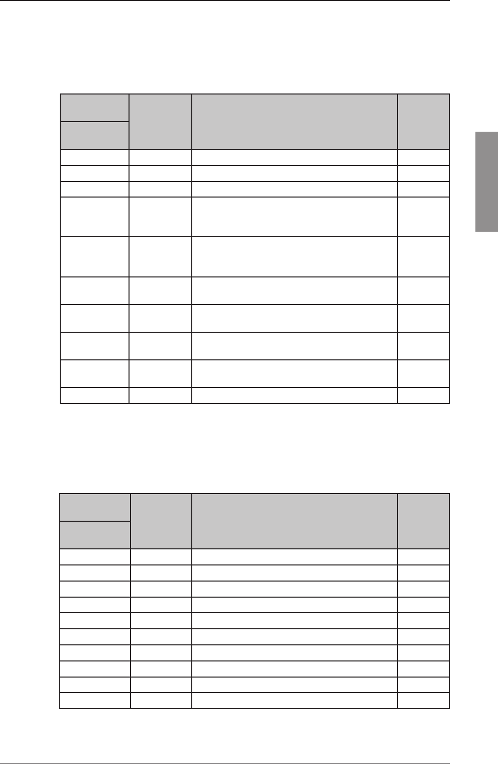
Table below shows the necessary cable cross sections and external fuse ratings.
150 W/250 W
Max. cable length to
battery*
Recommended Cable
Sceened multiwire External fuses
5 m 3 x 10 mm² (7 AWG) 40 A
8 m 3 x 16 mm² (5 AWG) 50 A
12 m 3 x 25 mm² (3 AWG) 63 A
500 W
Max. cable length to
battery*
Recommended cable
Sceened multiwire External fuses
4 m 3 x 16 mm² (5 AWG) 100 A
6 m 3 x 25 mm² (3 AWG) 100 A
2-17
Installation
Chapter 2: Installation
98-144591-A
DC Power cabling
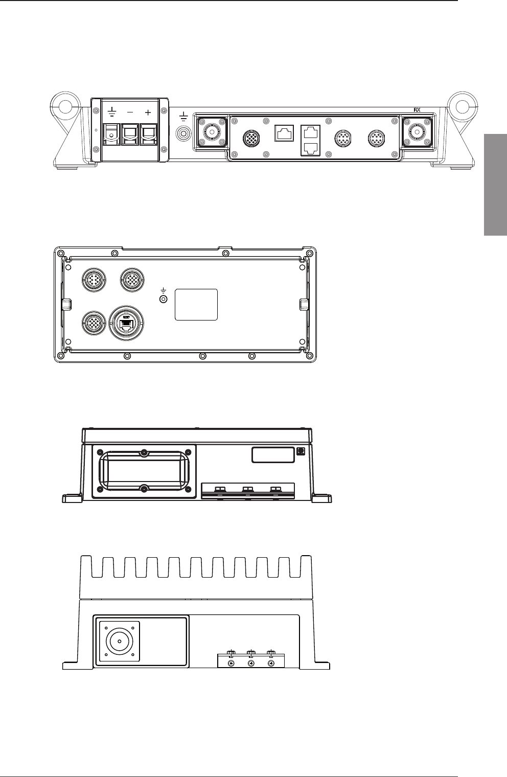
2.6 Interconnection of units
Transceiver Unit connector panel
TX
CU BUS
CU LAN
LAN
SYS COM
AUX
RX
24V DC
Control Unit connector panel
TU-CU BUS
AUX
LAN
ACC
150 W/250 W Antenna Tuning Unit connector pane
500 W Antenna Tuning Unit connector panel
TX/RX
TX/RX
TX/RX
TX/RX
2-18 Chapter 2: Installation 98-144591-A
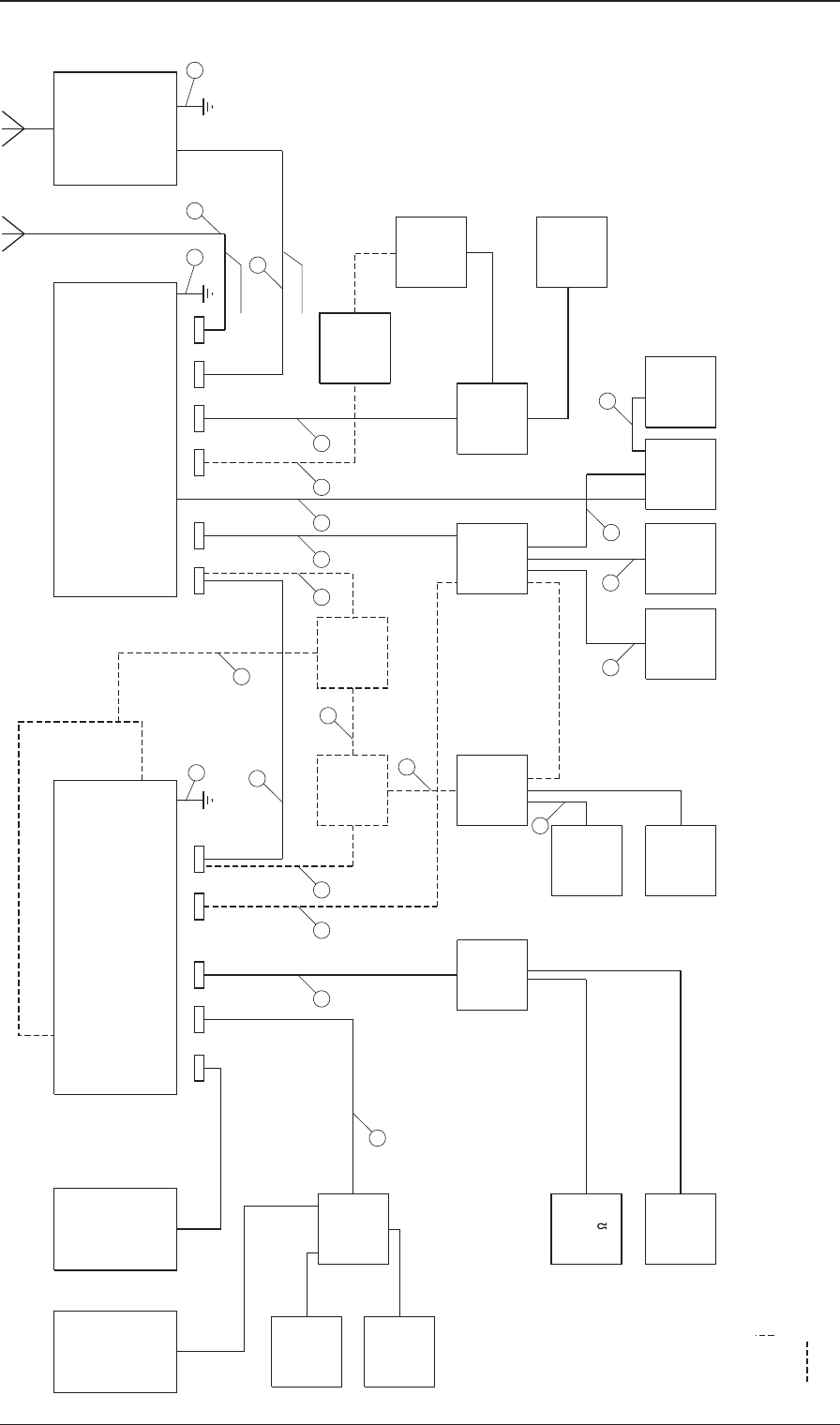
Interconnection of units
99-130929_6300B
Control Unit Transceiver Unit Antenna
Tuning
Unit
Handset
ACC AUX
TU-CU BUS
LAN
24VDC
RX
TX
Loud
speaker
2182 Selc
(optional)
External
DSC
Alarms
(optional)
AC
Power Supply/
Battery
Charger
LTW
12
Female
RG-213/U
3 4
6
TX
inhibit
(optional)
1
10
13
2
5
7
13
Please check the accessory list to find recommended power products
)
*
**
Please check the accessory list to find recommended loudspeaker
Please note that for distance less than 25 m the system will work with 0.25 mm² instead of 0.5 mm²
)
TU-CU
GNDLAN
Message
Terminal
LTW
12
Female
LTW
10
Female
Keyboard
Printer
12
RJ45
8
GPS
(optional)
406209A
Handset/
Hand-
microphone
(Back)
Handset/
Hand-
microphone
(Front)
LTW
10
Female
14
GND
AUX
TX
RJ45
LTW
12
Female
LTW
5
Female
LTW
10
Female
PL259 PL259
Ethernet
Switch
Alarm
Panel
Data
Modem
(Remote
24V
Battery
GPS
RG-213/U
12
**
)
)
*
"Optional"
(optional)
(optional)
"Optional/Service"
406208A
Control Unit
Conn. Box
11
406208A
Control Unit
Conn. Box
406209A
Accessory
Conn. Box
8
***
)
optional)
12 12
***
)
***
)
406208A
Control Unit
Conn. Box
15
12
3a 3a
Please note power separately
Option
3a
Control Unit
SYS CON
406209A
Accessory
Conn. Box
9
2-19
Installation
Chapter 2: Installation
98-144591-A
Interconnection of units
Cable 1: Control Unit - ACC
Cable: 10 x LTW-UL2464 26AWG
Cable-connector: 10 way (ex. LTW)
5 m cable with connector supplied
Control
Unit
Designation Remarks Color
'ACC'
10 way
LTW
1 NMEA+ NMEA position input Brown
2 NMEA- NMEA position input Blue
3 2182 Select OC output. Low when 2182 kHz is selected White
4 NC No Connection Green
5 MIC Handset microphone Yellow
6 EAR Handset earpiece Grey
7 HOOK PTT Hook and PTT Pink
8 +12 V DC 12 V supply to handset Red
9 GND System ground Black
10 GND System ground Orange
Cable 2: Control Unit - Ground
Recommended wire dimension: min. 2.5 mm2
Maximum length 0.2 m
Cable 3: Control Unit - Transceiver Unit
Cable: 12 x LTW-UL2464 20AWG
Cable-connector: 12 way (ex. LTW)
6 m cable with connectors supplied with equipment
Control
Unit
Transceiver
Unit
Tvisted
pair Designation Remarks Color
'TU-CU
BUS'
12 way
LTW
'TU-CU
BUS'
12 way
LTW
1 1 a SHIELD Screen connected to system ground Brown
2 2 b GND System ground Blue
3 3 b +24 V Supply voltage for the Control Unit White
4 4 c CAN Vcc CAN supply (15 V DC) Green
5 5 d CAN H CAN data H Yellow
6 6 d CAN L CAN data L Grey
7 7 c CAN GND CAN ground Pink
8 8 a SUPPLY_ON Supply on signal to the Transceiver Unit
Active when connected to GND Red
9 9 e AUDIO IN+ Balanced Audio IN Black
10 10 e AUDIO IN- Orange
11 11 f AUDIO OUT+ Balanced Audio OUT Violet
12 12 f AUDIO OUT- Cyan

2-20 Chapter 2: Installation 98-144591-A
Interconnection of units
Cable 3a: 2nd Control Unit - Transceiver Unit
If a 2nd control unit is installed, this can be done by splitting and extending the CAN bus, using e.g.
the 406208A control unit box.
Note that the CAN bus must be terminated with 120 Ohm in each end of the bus (not in the middle!).
The transceiver unit is terminated per default. Move Jumper W402 placed just inside the transceiver
unit, if termination is not needed in the place the transceiver is installed. In this case, termination
must added at both control units.
Cable 4: Transceiver Unit - TX Antenna
Cable: 50 ohm coaxial cable RG213/U (or better)
Maximum cable length 100 m
Cable-connector: UHF connector PL259, Crimp type connector should be used.
Cable 5: Transceiver Unit - Ground
Recommended wire dimension: min. 10 mm2
Maximum length 0.2 m
Cable 6: Transceiver Unit - RX Antenna
Type: 50 ohm coaxial cable RG213/U (or better)
Maximum cable length 100 m
Cable-connector: UHF connector PL259, Crimp type connector should be used.
Cable 7: Antenna Tuning Unit - Ground
Copper strap 100 x 0.5 mm or 3 x 6 mm shielded cable with wires and shielding connected to ATU
GND and shielding left open at the other end.
Refer to section ‘Ground Connections’
Cable 8: Control Unit – AUX
Cable: 12 x LTW-UL2464 20AWG
Cable-connector: 12 way (ex. LTW)
6 m cable with connector, available from eShop
Control
Unit
Designation Cable
no. Remarks Color
'AUX'
12 way
LTW
1 NC 10 No Connection Brown
2 NC 11 No Connection Blue
3 NC 11 No Connection White
4 NC 9 No Connection Green
5
OTHER DSC
ALARM
8 + 5 V output, when active Yellow
6 NC 10 No Connection Grey
7 DISTRESS
ALARM
10 + 5 V output, when active Pink
8 GND 9 System ground Red
9 SPEAKER OUT 8
External speaker (max. 6W in 8 ohm)
Black
10 NC 10 No Connection Orange
11 NC 11 No Connection Violet
12 NC 12 No Connection Cyan
2-21
Installation
Chapter 2: Installation
98-144591-A
Interconnection of units
Cable 9: Transceiver Unit - AUX
Cable: 10 x LTW-UL2464 26AWG
Cable-connector: 10 way (ex. LTW)
6 m cable with connector, available from eShop
Transceiver
Unit Designation Remarks Color
'AUX'
10 way LTW
1 NMEA_IN+ NMEA position input Brown
2 NMEA_IN- NMEA position input Blue
3 GND System ground White
4 LINE_OUT
Single ended 600 ohms AF output
Nominal 0 dBm in 600 ohm
Refers to system ground (GND)
Green
5 LINE_IN
Single ended 600 ohms AF input
Nominal level 0 dBm
Refers to system ground (GND)
Yellow
6 TX_INHIBIT
Transmitter inhibit/RX mute input Pulled up to +15 V
Active when connected to GND Grey
7 TX_KEYED Low when TX keyed
OC output, max. 50 mA, 12 V Pink
8 12V_OUT +12 V output
Max. 50 mA Red
9 EXT KEY Transmitter key input. Pulled up to +15 V
Active when connected to GND Black
10 GND System ground Orange
Cable 10: Transceiver Unit - SYS CON
Cable: 10 x LTW-UL2464 26AWG
Cable-connector: 10 way (ex. LTW)
6 m cable with connector, available from eShop
Transceiver
Unit Designation Remarks Color
'SYS CON'
10 way LTW
1 NMEA_IN+ NMEA input Brown
2 NMEA_IN- NMEA input Blue
3 NMEA_OUT+ NMEA out White
4 NMEA_OUT- NMEA out Green
5 Test_TX Reserved for factory test
Yellow
6 Test_RX Reserved for factory test
Grey
7 PPS+ Future use (1 Hz Puls input)
Pink
8 PPS- Future use (1 Hz Puls input)
Red
9 AC_ALR Supply Alarm input, active low
Black
10 GND GND
Orange

2-22 Chapter 2: Installation 98-144591-A
Interconnection of units
Cable 11: Message Terminal
Cable: Shielded high quality USB-cable
Maximum cable length 1 m
Cable 12: Ethernet
Cable: STP/FTP CAT-5E or better
Maximum cable length 100 m
Cable 13: Transceiver Unit – 24 V Battery
For power cable information see section 2.6 DC Power Cabling
Cable 14: Message terminal
Cable: 5 x LTW-UL2464 24AWG
5 m cable supplied with Telex option kit
Message
terminal Designation Remarks Color
SAILOR 6208
Control Unit
Connecton Box
'NMEA'
5 way LTW Pin number
1 System GND GND 1
2 CAN S CAN Vcc Red 4
3 CAN C CAN GND Black 7
4 CAN H CAN H White 5
5 CAN L CAN L Blue 6
Cable 15: Control Unit - Transceiver Unit
Maximum cable length 100 m
For extended cable length, use shielded twisted pair cable 6x2x0.5mm2 or better
For connection details refer to wiring table for cable 3.
2-23
Installation
Chapter 2: Installation
98-144591-A
Interconnection of units
2.7 Position and time information
2.7.1 Connection of Navigation Equipment
Navigation equipment complying with the NMEA 0183/IEC 61162-1 standard may be connected for
automatic position and time updating. Connection is made to the NMEA+/NMEA- connections in the
Control Unit ACC connector or the NMEA+/NMEA- connections in the Transceiver Unit AUX connector.
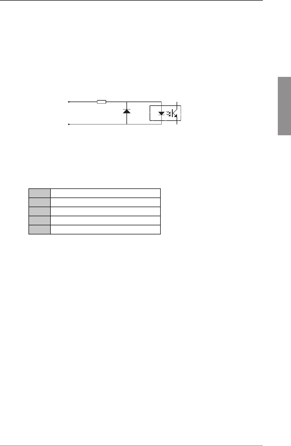
The NMEA receive circuit consists of an optoisolator with a 470 ohms series resistor to insure current
mode operation and a shunt diode to limit reverse bias as shown below. The circuit is isolated from ground.
NMEA IN -
NMEA IN +
A
B
The circuit operates with a minimum
differential input voltage of 2 volts
and draws less than 2 mA from the
line at that voltage. The maximum
voltage is 15 volts.
Interconnection between devices may be by means of two-conductor shielded twisted-pair cable.
Multiple listeners may be connected to a single talker. The receivers are connected in parallel. The shield
should be connected to the navigator chassis and should not be connected at any listener. However the
shield should be continuous (unbroken) between all listeners.
Supported sentences:
GLL (longitude, lattitude, utc, status, mode)
GGA (longitide, lattitude, utc, quality )
RMC (longitude, lattitude, utc, status, mode)
GNS (longitude, lattitude, utc, mode)
ZDA (utc, day, month, year)
Only the mentioned fi elds are used - the rest are discarded.
NMEA data on the LAN-connection is also accepted. This data should comply with IEC 61162-450.
2-24 Chapter 2: Installation 98-144591-A
Position and time information
2.8 Telex operation
The GMDSS Radiotelex Terminal is designed in accordance with relevant IMO, ITU and ETSI recom-
mendation/specifi cations and has been approved for shipboard installations to be operating within the
Global Maritime Distress and Safety System.
It supports world-wide ship-to-ship, shore-to-ship and ship-to-shore communication by utilizing the
radiotelex protocols described in ITU-R M.625. In case of two-way communication an ARQ (Automatic
Repetition reQuest) algorithm is used, and when broadcasting FEC (Forward Error Correction) is used.
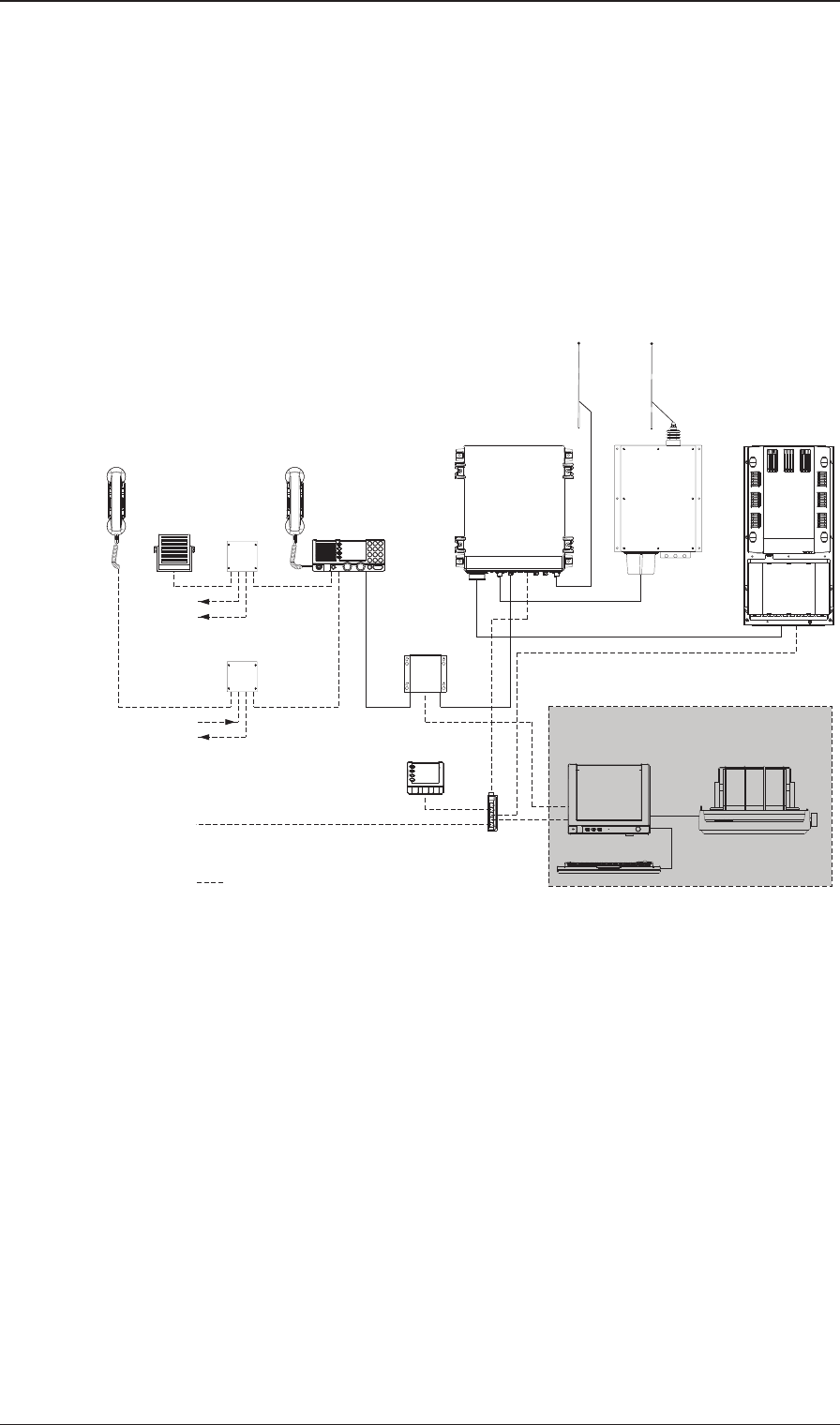
TT-6209A
Accessory
Connection Box
TT-6209A
Accessory
Connection Box
Unit
Antenna Tuning
Tx
Handset
TT-638xB
Message Terminal
DSC Watch receiver
250W MF/HF with 6 ch. Scanning
TT-636xB
(Optional)
Keyboard
MF/HF Control Unit
TT-630xA
Alarm Panel
TT- 6103A
Ethernet Switch
TT-6197A
Handset
GPS option
2182 select option
TT-6270A
Power Supply
TT-608xA
Connection Box
Control Unit
Distress Alarm
Other Alarm
TT-6201A
Transceiver Unit
TT-6201A
TT-6208A
TT-6001A
TT- 6006A
(Optional)
Rx
GPS on LAN option
Optional connection
Telex option
Printer
H1252B
2-25
Installation
Chapter 2: Installation
98-144591-A
Telex operation
2.9 ID programming
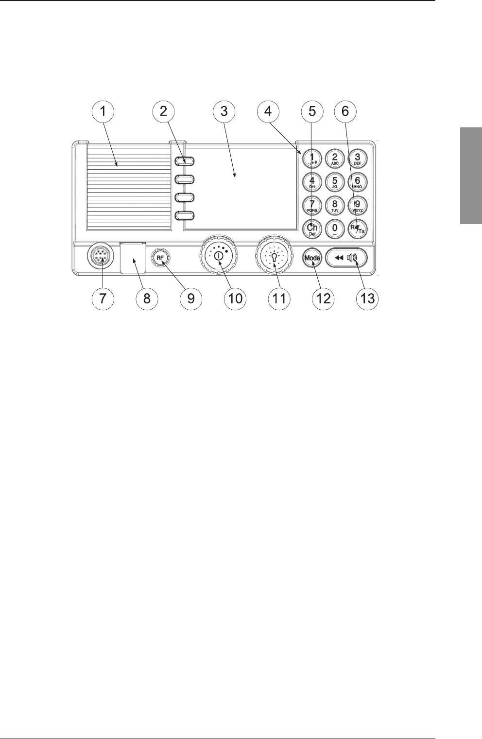
2.9.1 Front Panel
1. Loudspeaker.
2. Four soft keys with function title in the display.
3. Large TFT color display.
4. Alphanumerical keys to enter Rx or Tx frequency or text strings.
5. CH button for channel selection.
6. Rx/Tx Key to enter Tx or RX frequency.
7. Connector for handset or handmicrophone.
8. Distress button for sending a Distress alert.
9. RF gain control (IF).
10. Volume knob with key-press function for power on/off.
11. Selector and dim knob with key-press function for radio operation and setup.
12. Mode key to select the work mode: SSB, AM Broadcast, DSC, Telex.
13. Replay button to play back up to 240 s voice messages.

2-26 Chapter 2: Installation 98-144591-A
ID programming
2.9.2 Set-up Menu
Menu items shown in bold is only available in the menu structure when it is extended by access password
>1-2-3-4-5< in the System Set-up menu.
Set-up Menu
Soft keys (2) Radio set-up Scan Hang Time
Scan Resume
Scan Mode
External PTT
LSB Mode: OFF
ATU: Enabled
TX AM 2182: Disabled
1 x > Channel Set-up Watch Receiver
Privat Channels
DSC Watch
TX Band
2 x > Power Supply Monitor: OFF
3 x > DSC Set-up Position & MMSI
DSC Groups
Auto- Ack Test
Auto-Ack Polling
Auto-Ack Position
Auto-Ack Individual
Non-Distr. Inactivity
Distress Inactivity
Comm. Inactivity
Non-Distr. Alarms
Self-Term. Distr. Alarms
Medical Transport
Neutral Crafts
Print DSC
DSC self-test
4 x > DSC Call Log Received Distress
Transmitted Calls
Received Calls
5 x > System Set-up Printer Confi guration
System Time & Date
Inactivity Timeout
Language
Theme
GPS Input
Diagnostics
Factory Defaults
Password
Reset MMSI no
Radio Info
6 x > Controller Set-up Handset 1 Vol
Handset 2 Vol
Wheel Lock
High Priority
Controller Set-up
7 x > System Confi g 6 Ch WR: Disabled
Telex: Disabled

2-27
Installation
Chapter 2: Installation
98-144591-A
ID programming
2.9.3 Change / reset MMSI
MMSI no is requested at ‘fi rst time power up’ and directly programmed via the numeric keyboard (4)
If a MMSI reset or change of registration is needed it is accessed via the Set-up Menu:
Operation Key Operation Function
Press 2 2 x More
2 Set-up
2 5 x > System Set-up
Scroll down to 11 Rotate Password
Select (press) 11
Key in 4 1-2-3-4-5
Scroll down to 11 Reset MMSI Number
Select (press) 11 Yes
Key in MMSI 4 9 digits 123456789
2-28 Chapter 2: Installation 98-144591-A
ID programming
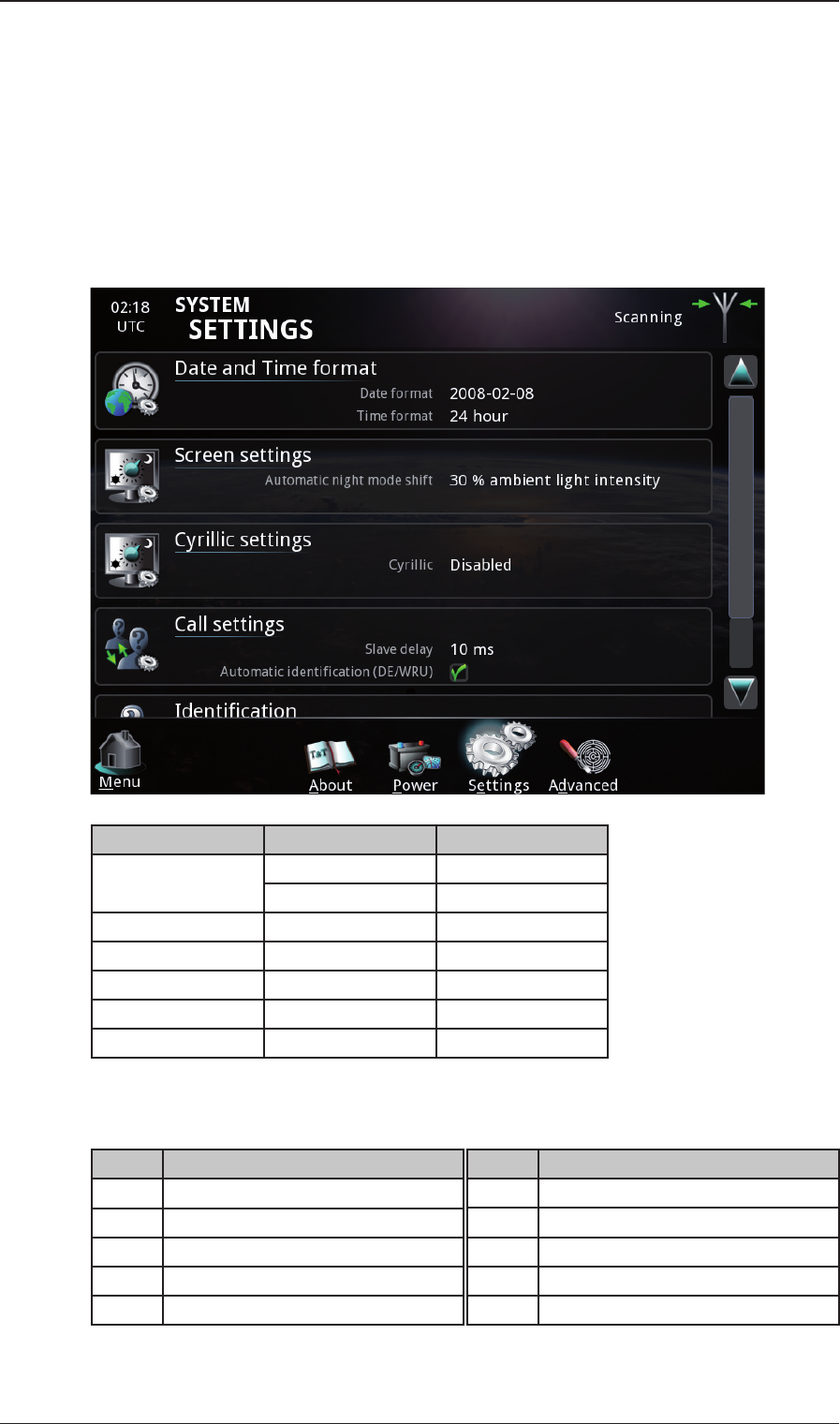
2.10 Programming Telex ID
Programming Telex ID is done via the in SAILOR 6006 Message Terminal.
Requires that the Telex option has been enabled in the radio (see ‘Option Code Activation’) and TLX
mode selected on the Control Unit (12).
The MMSI (9 digits) is automatically transferred from radio to SAILOR 6006 Message Terminal when
TLX mode is selected.
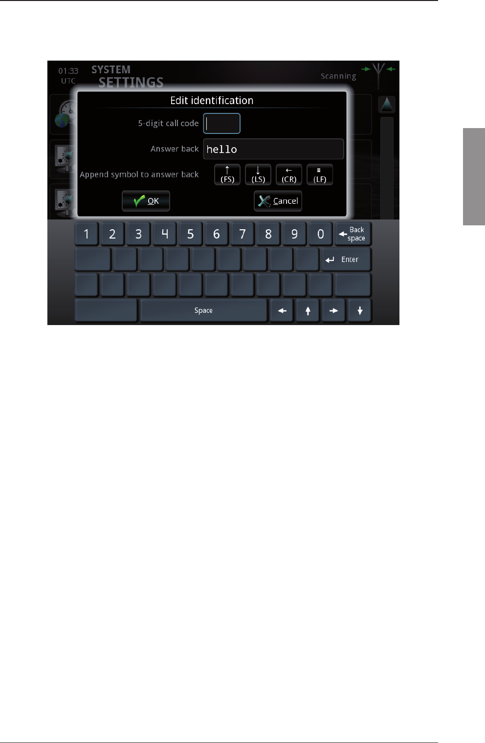
5 digit TLX call code and answerback is programmed on screen via the SAILOR 6006 Message terminal.
Operation Key Action
Press Settings
Identifi cation
Key in Pswd 1-2-3-4
Key in 5 digit call code (1-2-3-4-5)
Press Answer back
Key in* Answer back max 20 characters
Press OK
If a 5 digit TLX call code has not been issued or otherwise is not available, insert 5 x 2 (22222) to indi-
cate invalid call code.
*
Step Action
1 Figure shift (FS)
2 Carriage return (CR)
3 Line feed (LF)
4 5 or 9 digit call ID
5 letter shift (LS)
Step Action
6 Space
7 Abbreviated ID
8 Space
9X
10 Letter shifts to obtain 20 characters
2-29
Installation
Chapter 2: Installation
98-144591-A
Programming Telex ID
Figure Shift (FS), Letter Shift (LS), Carriage Return (CR) and Line Feed (LF) are normally not required
inserted in the answerback.
2-30 Chapter 2: Installation 98-144591-A
Programming Telex ID
2.11 Confi guration
The GMDSS approved radio is by default confi gured to meet the legislative requirements and restrictions.
Optional functionality may be confi gured and will normally require national exemptions to be utilized.
Confi guration and test facilities, which are considered ‘user facilities and basic settings’, are available
via the menu structure.
Further confi guration possibilities are available behind the access password >1-2-3-4-5< indicating that
any changes in this area will affect the system operation and therefore should be done with caution.
Other confi gurations considered installation features are accessed via the Service Interface.
Please refer to the '97-147768 – User manual SAILOR 6300B MF/HF Service Interface', available for
download at Cobham extranet.
2.11.1 CU confi guration
Priority setting is via the menu and Main CU is High Priority = ON and Slave CU is High Priority = OFF.
Operation Key Operation Function
Press 2 2 x More
2 Set-up
2 3 x > Controller Set-up
Scroll down to 11 Rotate High Priority
Select 11 Press
Select 11 Rotate High Priority = ON/OFF
Press 2 Exit To store
2.11.2 ATU confi guration
ATU is default enabled.
ATU enable/disable is confi gured via the Service Interface.
Only disable ATU when testing on 50 load or using a dedicated antenna matched for a certain frequency.
2.11.3 DSC printing ON/OFF
Operation Key Operation Function
Press 2 2 x More
2 Set-up
2 3 x > DSC Set-up
Scroll down to 11 Rotate Print DSC: OFF
Select 11 Press
Select 11 Select ON/OFF
LAN connected printer can now be selected to print DSC messages from the log. A SAILOR 6004 Control
Panel with printer is also accepted. Please check ‘2.12.4 DSC Printer Confi guration’ for setup.
2-31
Installation
Chapter 2: Installation
98-144591-A
Confi guration
2.11.4 DSC Printer confi guration
Operation Key Operation Function
Press 2 2 x More
2 Set-up
2 5 x > System Set-up
Scroll down to 11 Rotate Printer confi guration
Select 11 Press
2.11.5 DSC self test
Menu Key Operation Function
3 x > 2 DSC set-up
Scroll 11 DSC Self Test
Press 11 Select RUN
Press 11 To Activate
System start TX test With DSC call on 2187.5 kHz to own WR.
2.11.6 Factory default/reset
Factory default is a ‘User defi ned’ reset of settings and address books etc.
Operation Key Operation Function
Press 2 2 x More
2 Set-up
2 5 x > System Set-up
Scroll down to 11 Rotate Factory Default
Press 11 Select Continue Factory Reset
Select 2 Yes / No Factory Resetting
Please wait up to 30 sec.
System reboot and Control Unit connecting to radio.
2.11.7 Factory reset via service tool
Factory reset will bring all ID and confi guration settings in the radio system back to factory level as a
new system and is performed via the Service Interface or in the protected menu on the Control Unit.
Options already enabled in the system will remain activated. Resetting of options require separate
operation via the Service Interface.
2.11.8 LSB mode confi guration
LSB (Lower Side Band) mode is confi gured via the Service Interface or in the protected menu.
GMDSS radios require SSB operation in USB (Upper Side Band) mode and may only have LSB mode
enabled on a special exemption depending on national requirements where the ship is registered.
Radios installed and operated as ‘non-GMDSS radios’ can have LSB enabled.
2-32 Chapter 2: Installation 98-144591-A
Confi guration
2.11.9 Option code activation
6-channel Watch Receiver and Telex functions are optional features and are thus disabled in the radio
as supplied from factory.
Both functions are enabled by inserting a unique 10 digit option code for each via the System Confi -
guration in the Set-up menu:
Operation Key Operation Function
Press 2 2 x More
2 Set-up
2 6 x > System confi guration
Select 11 6 CH WR Option Code
Key in DSC6 option code 2 xxxxxxxxxx Enabled
Scroll down to 11 TLX mode Option Code
Key in TLX option code 4 xxxxxxxxxx Enabled
The 10 digit option codes for 500 W systems are foc and supplied with equipment (not programmed).
The 10 digit option codes for 150 W/250 W systems may be ordered with the system or any time later.
DSC6 option code part number: 406300-006
TLX option code part number: 406300-001
DSC6 and TLX option codes are unique to each radio and generated on basis of the TU serial number
and locked to this.
Option codes already generated either through purchase or as factory supplied for the 500 W systems
may be looked up in the ‘Confi guration Key Search’ at www.cobham.com/satcom.
Options already enabled in a system will remain activated even after ‘Factory default’ and ‘Factory Reset’
operation. To disable these optional functions requires reset of the respective option code using the
Service Interface.
2.11.10 Power Supply monitoring
This item requires a SAILOR 6081A located on same LAN network segment as the TU.
Power Supply monitoring is by default set ‘OFF’ from factory.
When the Power Supply monitoring is set ‘ON’ the TU ‘Supply Alarm’ connector becomes active and
ready for interconnection to the Power Supply/Charger in order to monitor ‘AC Alarm’ and ‘Battery
High/Low Voltage Alarm’ states.
The Power Supply monitoring function meets the GMDSS requirements for AC fail and Battery voltage
alarms with acoustic and visual indication on the Control Unit.
Operation Key Operation Function
Press 2 2 x More
2 Set-up
2 2 x > Power Supply
Select 11 Press Monitor
Scroll 11 Select Enabled/Disabled
Select 11 Press Enabled
Press 2 OK Enabled
Press 2 Exit
Detailed Power Supply and Charger confi guration is available in the in the SAILOR 6081 Power Supply
Unit and Charger Installation & User Manual.
2-33
Installation
Chapter 2: Installation
98-144591-A
Confi guration
2.11.11 TX band confi guration
Operation Key Operation Function
Press 2 2 x More
2 Set-up
2 1 x > Channel Set-up
Scroll down 11 Rotate TX-Band
Select 11 Press
Press 2 Add New band
Key In Band limits 4 1605,0
26175,0
The freqs wanted
Press 2 Save Free run TX
2.11.12 Watch Receiver settings
Operation Key Operation Function
Press 2 2 x More
2 Set-up
2 1 x > Channel Set-up
Select 11 Press Watch Receiver
This menu will show watch receiver frequencies.
2.11.13 Special confi guration
Ship counter part confi guration and special facilities are confi gured via the Service Interface.
Please refer to 2.11 for details

2-34 Chapter 2: Installation 98-144591-A
Confi guration
2.12 Final installation check
Refer to ‘User Manual’ – chapter Service & Preventive Maintenance.

3-1
Technical description
Chapter 3: Technical description98-144591-A
Technical description
3.1 Control Unit
The Control Unit consists of a main module 60-127962 and two sub modules: HMI module 60-127963 and the
Intercon module 60-127964.
The main module consists of the digital part, i.e. the microprocessor, program FLASH, SDRAM, TU-CU Bus commu-
nication driver and Ethernet interface.
The main module also consists of an analog part, i.e. the voltage regulators, the analog interface circuits and the
analog output drivers (audio and light). The main module supports a build-in speaker and the connectivity of an
external 8 ohm speaker. The module also controls the the graphical TFT color display (240x320 dots).
The HMI module contains a small keyboard interface and encoders for volume and rotary knob.
The Intercon module contains the connectors for external interfaces.
3.2 Transceiver Unit
The Transceiver Unit consists of four modules. Two modules located in the base part of the unit: a Supply Filter
module, an Exciter Control module, and two modules are located in the door part of the unit: a power amplifi er
module including fi lter bank and a switched mode power supply. The main wiring is by ribbon cables with Micro
Match connectors. RF signals are routed in coaxial cables.
3.3 Supply Filter module 57-139985
To reduce electromagnetic interference even when transmitting at high power, a supply fi lter PCB consisting of a
common mode choke and high voltage decoupling capacitors is integrated in the transceiver unit.
There are no serviceable parts on this PCB.
3.4 Exciter Control module (ECM) 60-139984
The ECM board is the main board of the system 6000B MF/HF. This board consists of the following main items:
• Local power supplies generating supplies to the integrated circuitry present on the ECM board.
• RF input with Surge Arrester (90VDC +/-20% and in accordance with ITU-T Rec. K.12 and
DIN 57845/VDE0845) .
• Anti-aliasing and power line noise fi lter with pass band of 150kHz to 30MHz.
• Variable Gain Amplifi er and input overload protection.
• 16 bit Analog to Digital Converter sampled at 98.304MHz generated by 0.3ppm local oscillator
on 17.8176MHz
• FPGA doing direct sampling, multiple receiver chains, fi ltering, SWR protection and direct
up-conversion transmitter chain.
• Flash ADC used as input to protection circuitry yielding response time in microseconds towards
bad SWR.
• Dual TX DAC modulating directly on the transmitter frequency.
• Broad band high linearity amplifi er outputting RF signal at approximately +9 dBm.
• DSP for signal processing, modulation schemes, power loop, modem and ATU control.
• FSK modem for communication with the antenna tuning unit.
• ARM processor with DDR3 RAM and eMMC Flash for LAN connectivity, control and boot of
other peripherals. Furthermore, NMEA, real time clock and CAN.
Chapter 3
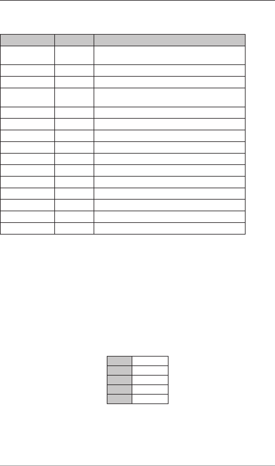
Chapter 3: Technical description3-2 98-144591-A
LEDs on the ECM boards can be used to verify the following items:
LED Normal state Status
FPGA A Off Transmit protection detected in current PTT session (reset
when PTT is released and pressed again)
FPGA D Off Reset from CPU has not been detected after FPGA boot.
FPGA B Blink Reserved
FPGA C Blink Reduced DAC clock ~2.93Hz – not necessarily in phase with
FPGA LED
FPGA OWRFLW Off ADC Overfl ow
FPGA ALIVE Blink Alive led – Shall blink at ~2.93Hz
LED C - On when transmitting – on while tuning – off in RX
LED B Off Lit if SWR protection is engaged
LED A - On when transmitting – off during tune – off in RX (TX monitor)
CPU HB Blink Kernel heartbeat
ARM CPU ALIVE Blink MFHF Application heartbeat
CPU Act Blink Off when CPU is idle
eMMC Act - Blinks when accessing fl ash fi le system
STATUS Blink DSP is running
ALIVE Off
3.5 PA and Filters module 60-122881
The PA and Filters module includes PA drivers, PA-stage, protection circuits, bias circuits, key circuit and fi ve low-
pass fi lters with relays and relay drivers. The PA and Filters receive the modulated RF input signal from the RX/EX
Signal Path and delivers the amplifi ed and fi ltered output signal to the TX/RX connector via a receive/transmit relay
on the Control/Intercon module.
The low-pass fi lters remove the unwanted harmonic frequencies from the PA signal. The Filpeak and PAprotec outputs
are monitoring signals for the Control/Intercon module. The driver and fi nal power amplifi er stages are galvanically
isolated on input and output as they are supplied directly from the 24 V DC input. The selection of low-pass fi lter is
controlled by the Control/Intercon module.
The PA fi lters cover the frequency ranges:
1.6 3.1 MHz
3.1 5.0 MHz
5.0 9.0 MHz
9.0 17.0 MHz
17.0 29.7 MHz
Technical description

3-3
Technical description
Chapter 3: Technical description98-144591-A
3.6 PA and Filters module 60-123937 (FCC)
The PA and Filters module includes PA drivers, PA-stage, protection circuits, bias circuits, key circuit and fi ve low-
pass fi lters with relays and relay drivers. The PA and Filters receive the modulated RF input signal from the RX/EX
Signal Path and delivers the amplifi ed and fi ltered output signal to the TX/RX connector via a receive/transmit relay
on the Control/Intercon module.
The low-pass fi lters remove the unwanted harmonic frequencies from the PA signal. The Filpeak and PAprotec outputs
are monitoring signals for the Control/Intercon module. The driver and fi nal power amplifi er stages are galvanically
isolated on input and output as they are supplied directly from the 24 V DC input. The selection of low-pass fi lter is
controlled by the Control/Intercon module.
The PA fi lters cover the frequency ranges:
1.6 2.3 MHz
2.3 3.05 MHz
3.05 4.5 MHz
4.5 8.8 MHz
8.8 16.81 MHz
16.81 19.0 MHz
19.0 30.0 MHz
3.7 SMPS module 60-122882 (150 W/250 W)
The Switched Mode Power Supply supplies the low power circuits of the equipment with the various stabilized voltages
required, and provides galvanic isolation from the supply source. The equipment is supplied from a 21.6 – 31.2 V DC
power source. The module also carries the input fi lter and PA supply output which is not galvanically isolated.
The power supply converts the incoming voltage to 7.5 V, +15 V, -15, and 25 V. The SMPS is switched on from the
Control Unit via the TU-CU Bus SUPPLY ON wire and switched off under software control via the SUPPLY ON/OFF
connection from the Control/Intercon module. The DC supply voltage is sensed by a BAT INFO detector circuit and
fed to the Control/Intercon module for automatic RF output power adjustment.
3.8 SMPS module 60-126172 (500 W)
The Switched Mode Power Supply supplies the low power circuits of the equipment with the various stabilized voltages
required, and provides galvanic isolation from the supply source. The equipment is supplied from a 21.6 – 31.2 V DC
power source. The module also carries a protection circuit for over/under voltage, wrong polarity and error detection.
This circuit operates a relay on SMPS module 60-126136.
The power supply converts the incoming voltage to 7.5 V, +15 V, -15, 25 and 30 V. The SMPS is switched on from
the Control Unit via the Scanbus SUPPLY ON wire and switched off under software control via the SUPPLY ON/OFF
connection from the Control/Intercon module. The DC supply voltage is sensed by a BAT INFO detector circuit and
fed to the Control/Intercon module for automatic RF output power adjustment.
Technical description
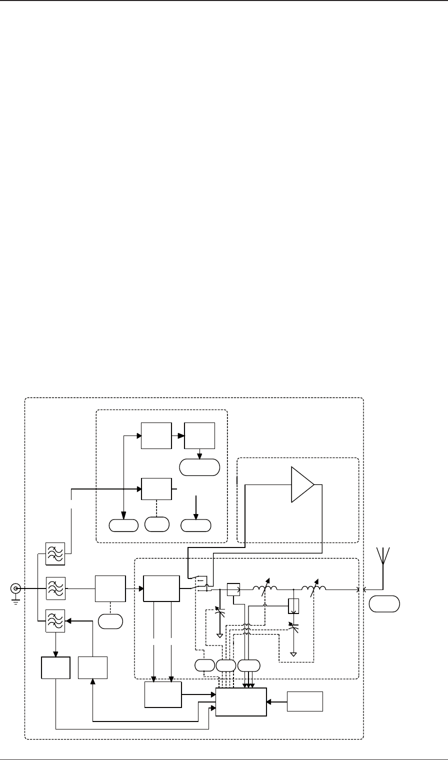
Chapter 3: Technical description3-4 98-144591-A
3.9 SMPS module 60-126136 (500 W)
This switched mode power supply contains a common input fi lter for 60-126136 and 60-126172 and supplies the
PA. The input and output are galvanically isolated, and the output is fl oating with regards to ground.
The supply for the PA is 45 V, and is switched on with the HT On connection. A reduced voltage for the PA is avai-
lable in Telex-mode.
A fan blower control circuit is also employded. As the PA and / or the SMPS heats up, the fans will be activated.
Should the temperature reach unsafe levels, the power for the PA will be switched off.
3.10 Antenna Tuning Unit
3.10.1 ATU module 60-122883 (150 W/250 W)
The ATU module comprises of a tuning network, measuring system and micro-controller circuits. The ATU module
matches the impedance of the antenna to 50 ohm in order to gain the best possible SWR towards the TU. The TU
communicates tuning process and frequency information with the ATU. The tuning network consists of capacitor bank
1, capacitor bank 2, and an inductor bank. With these banks it is possible to form either an L-network or a pi-network.
The capacitor banks and inductor bank are built up by binary related capacitors and coils. The setting of capacitance
and inductance is accomplished by relays. To prevent overload of the relays, current detectors are incorporated in
the inductor bank and in capacitor bank 2 and information fed back to the transceiver unit to decrease the output
power if maximum permissible current is exceeded. To prevent overheating a temperature sensor is incorporated
which at excessive temperatures commands the transceiver to reduce the output power.
In receive mode an RX-Amplifi er included in the Antenna Tuning Unit is utilized, to improve the sensitivity of the
system by providing 50 ohm impedance. This is only used when connected to a 6000A MF/HF System.
Block diagram
Tune Att.
4 dB
Directional
Coupler
26dB
Vw
Vref
Micro Prosessor
L-bank L-bank
Tuning circuit
RX/TX/
ATU/COM
24V DC
Rx
Amp
Antenna
Connector
Horn
Antenna
Temperature
sensor
Modem filter
Demodulator
Modulator
RF filter
24V
5V
regulator
to relays
to digital
circuits
13/24V
SMPS
to relays
24V in Rx & Tune Tx
13V in Tx
DC regulators
IL detector
Ic
detector
CB2
control by
uP
rx
tx
control by
uP
current
detectors
RX amplifier
Phase &
Voltage
Detectors
control
banks
CB1
control
Rx/Tx
High Pass Filter
40637_6300B
regulator
12V
Transceiver unit block diagram (150W/250W)
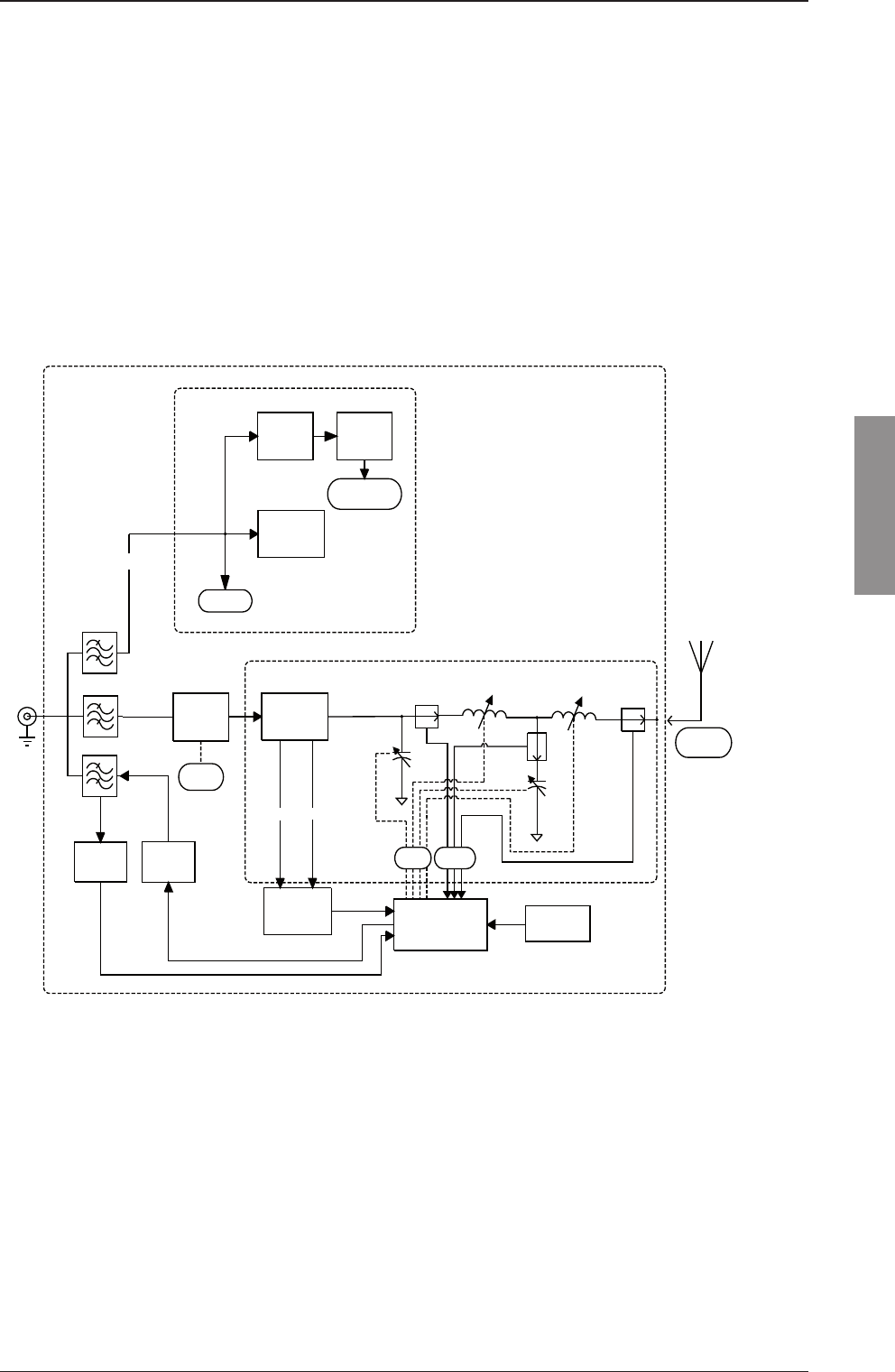
3-5
Technical description
Chapter 3: Technical description98-144591-A
3.10.2 ATU module 60-131020 (500W)
The ATU module comprises of a tuning network, measuring system and micro-controller circuits. The ATU module
matches the impedance of the antenna to 50 ohm in order to gain the best possible SWR towards the TU. The TU
communicates tuning process and frequency information with the ATU. The tuning network consists of capacitor bank
1, capacitor bank 2, and an inductor bank. With these banks it is possible to form either an L-network or a pi-network.
The capacitor banks and inductor bank are built up by binary related capacitors and coils. The setting of capacitance
and inductance is accomplished by relays. To prevent overload of the relays, current detectors are incorporated in
the inductor bank and in capacitor bank 2 and information fed back to the transceiver unit to decrease the output
power if maximum permissible current is exceeded. To prevent overheating a temperature sensor is incorporated
which at excessive temperatures commands the transceiver to reduce the output power.
Block diagram
Tune Att.
6 dB
Directional
Coupler
31dB
Vw
Vref
Micro Prosessor
L-bank L-bank
Tuning circuit
RX/TX/
ATU/COM
24V DC
Antenna
Connector
Horn
Antenna
Temperature
sensor
Modem filter
Demodulator
Modulator
RF filter
24V
5V
regulator
to relays
to digital
circuits
DC regulators
IL detector
Iant. detector
Ic
detector
CB2
control by
uP
current
detectors
Phase &
Voltage
Detectors
control
banks
CB1
High Pass Filter
99-126349
regulator
12V
Fan
Temperature
controlled
Transceiver unit interconnection diagram

Chapter 3: Technical description3-6 98-144591-A
3.11 Power control and protection system
The Transceiver has an automatic power level system, which ensures that optimum power is delivered to the An-
tenna. The Tune Sequence, which is automatically initiated when keying the transmitter after a frequency change,
makes the Tuning Network of the Antenna Tuning Unit tune to the best obtainable SWR. This is followed by an
Automatic Level Control (ALC) adjustment according to the available power supply voltage, measuring the output
current of the PA Filters (FILPEAK @ 10 Vp at full output), transmitting AM carrier, and setting the overall gain by
the ALC voltage. It is now possible to transmit at full output power unless protection is activated or LOW POWER is
selected. The output power is continuously monitored by the TU, and is automatically adjusted during transmission
to provide reliable communication.
3.11.1 Power Amplifi er Protection
The protection of the power amplifi er consists of V+I protection, SWR protection, and thermal protection. When
the output signal of the voltage detector at the output of the power amplifi er exceeds 10 V the output power is
reduced to a safe level. The thermal protection consist of a temperature sensor on the power amplifi er. The available
power supply voltage is measured in the DC power supply and the information is transferred to the ECM module.
If the supply voltage drops the microprocessor will adjust the output power to keep distortion below the limits.
3.11.2 Antenna Tuning Unit Protection
The ATU is protected by several detectors all monitored by the ATU's microprocessor, which calculates the SWR,
temperature, maximum voltage and current. If these parameters are not below safe operating limits it requests for
lower power.
Transceiver unit interconnection diagram
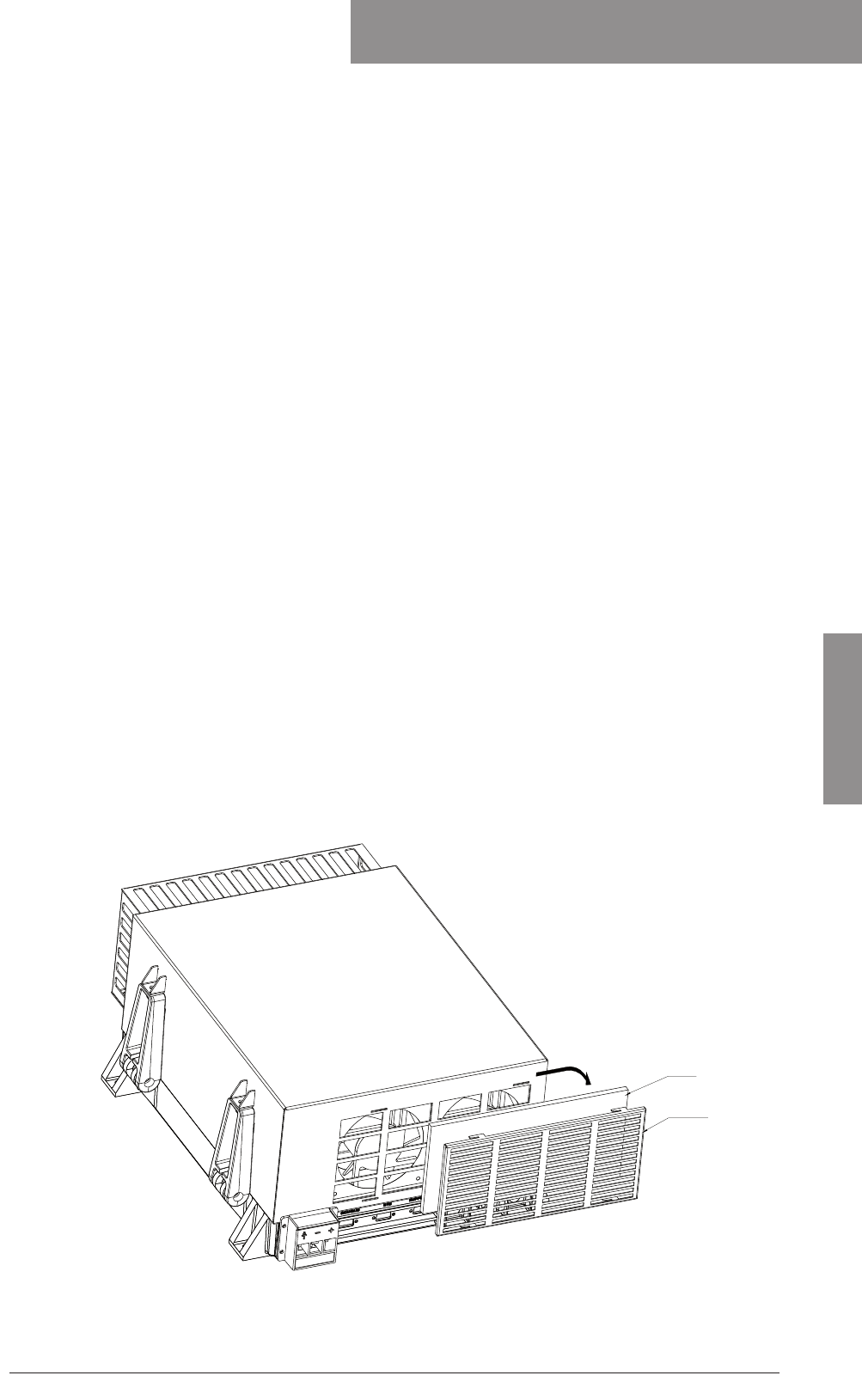
4-1
Service
Chapter 4: Service98-144591-A
Service
4.1 Preventive maintenance
Due to the modern design of the transceiver preventive maintenance can be reduced to a minimum
provided the equipment is correctly installed. To ensure maximum performance and minimum repair
trouble we recommend following the below stated items for preventive maintenance:
1. The condition of the battery should be checked at frequent intervals.
2. Check the condition of antenna installation, ground connection and cables at regular intervals.
Salt deposits on insulators must be removed with water to avoid fl ash-over when transmitting.
3. Keep antenna feed-through insulators clean.
4. Ensure that no objects are obstructing the free airfl ow through the cooling channels of the Transceiver
Unit and keep the units free of dust accumulation to prevent overheating.
5. For cleaning use a damp cloth. Sticky dirt may be removed using a cloth with a weak soap solution.
Wipe off with a clean cloth.
4.2 Cleaning the Air fi lter (500 W Transciver only)
The transceiver unit uses 2 fans to cool all circuitry inside the unit. To keep the cooling air clean an air
fi lter is placed in front of each fan. These air fi lters should be cleaned frequently, especially under dusty
working conditions. A clogged air fi lter will block effi cient cooling and the transmitter output power will
be reduced to avoid over-heating.
Remove the air fi lter cover from the buttom of the transceiver unit by gently pushing towards right and
pulling it out from the cabinet. Take out the air fi lters from the cover. Clean the air fi lters refi t and re-
assemble the unit.
Air filter
Filter cover
99-126839
Chapter 4

4-2 Chapter 4: Service 98-144591-A
Software update
4.3 System test and verifi cation
Ref to ‘User Manual’ – chapter 'Service & Preventive Maintenance'
4.4 Software update
For Software upload please refer to '97-147768 – User manual SAILOR 6300B MF/HF Service Interface',
available for download at Cobham extranet.
Latest SW for CU and TU is available for download at www.cobham/satcom.
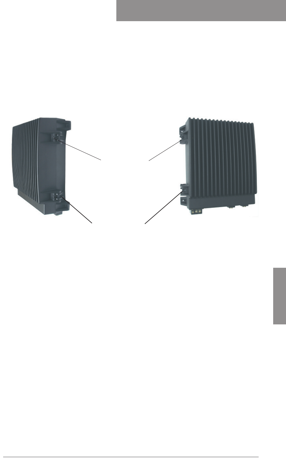
Chapter 5: Spare part exchange 5-1
Spare part exchange
98-144591-A
Spare part exchange
5.1
Disassembling the Transeciver
Init (150 W/250 W)
To open the transceiver unit loosen the 4 screws (2 on each side) on the side of the cabinet.
Move the screws to the side to unlock the TU. Now open the TU by pulling the front door towards you.
Loosen 4 screws
Screw A2 M6x30mm
87.838
Hinge Bolt,
ø11.4 x 27mm
238107
Hinge Bolt,
ø11.4 x ø27 x 54.5mm
238106
Chapter 5
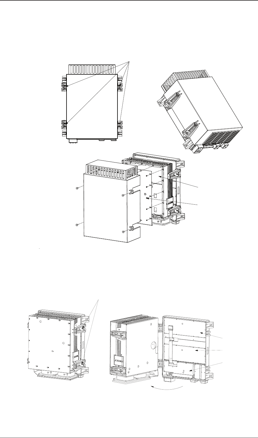
Chapter 5: Spare part exchange5-2 98-144591-A
5.2 Disassembling the Transceiver Unit (500 W)
To remove the transceiver cover loosen the 4 screws (2 on each side) on the side of the cabinet and
pull the cover from the transceiver.
99-126728
Loosen 4 screws
M6x16
SMPS modules
Loosen 17 screws
M3x8
To open the transceiver loosen the 2 screews on the right hand side of the cabinet.
99-126886
SYNTHESIZER and
RX/EX SIGNAL
CONTROL/
Loosen 2 screws M6x30
DSC WR module
PATH module
INTERCON module
Required service tool:
hexagonal socket wrench,
bits 1/4", length min. 16 cm.
Disassembling the Transceiver Unit (500 W)
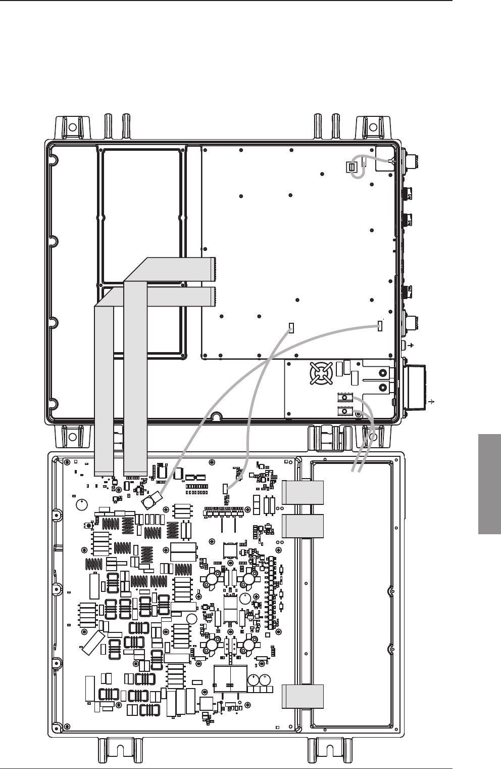
Chapter 5: Spare part exchange 5-3
Spare part exchange
98-144591-A
5.3 Transceiver Unit module location
150 W/250 W Transceiver Unit
The following modules are available as service parts.
C169
R51
R35
C44
C209
R26
R176
C35
C36
N3
R49
R46
C157
C194
C37
C38
H25
R50
V18
C195
C154
R162
C142
C158
H27
V50
V13
R36
H29
R136
R163
R130
H28
R132
C228
R131
R129
C153
R128
C205
R127
C198
C152
H6
C229
R137
H26
R38
V19
H21
H7
C189
R19
R173
H32
H24
R94
T1
E2
H33
C244
C182
H14
C19
V70
V47
C193
C150
R83
C100
R179
E1
H8
R169
R82
T2
C236
H30
C151
X16
H1
R149
V20
R85
H35
V21
H19
V6
R100
H4
C241
C177
R56
R2
R148
D4
N6
R71
H22
R37
C226
C23
C29
C191
C179
C197
C178
E3
H9
R89
R75
H37
C99
C192
C159
C160
C22
C30
C27
C190
C188
C196
V12
C161
C162
R161
H5
C165
V7
C203
V34
H20
V55
R98
R96
H12
C167
C166
R90
C2
C1
C69
H23
R84
C238
H17
X5
X3
H10
X4
H2
H13
H11
H16
X2
H18
H15
H31
D3
X100
C253
R154
C24
C25
C39
C9
C156
C174
C199
C200
C240
X17
V45
R70
N2
R158
R157
N4
R24
R25
V43
D1
C246
C168
C155
C181
R174
L21
C227
C11
C235
C208
V17
R55
C170
C171
L22
C28
R18
C101
C206
C57
C67
C237
C239
C52
C53
R159
H41
H42 H43
H44
H48
H49
C54
C176
C175
C183
T3
R178
R95
R155
C107
C121
R80
C13
C15
C14
C249
R7
C8
L1
R164
C10
V46
V30
C123
R5
R6
R12
V10
V9
V8
V11
V59 V60
R102
R21
R20
C7
C6
R22
R181
R23
C124
R182
R10
R17
R15
C137
R9
C4
R11
C18
V33
R92
R166
C59
V37
V53
V42
R91
R139
R140
C113
V44
R69
C255
R202
R203
H47
V71
C95
C254
R134
R175
R3
R4
R14
R86
N1
X11
V4
V5
R146
C212
R145
R144
R143
R77
R79
R81
R147
R1
R151
R152
R153
R31
R66
C114
R185
R53
C102
C103
R52
R165
C242
C173
C180
C172
C48
C73
C108
R106
R105
R104
R103
R97
K10
L31
X7
L40
R123
R124
R126
C134
R112
C75
C221
K8
L12
K3
C85
R42
R43
C147
L42
R125
R122
L41
R116
L56
L51
R114
R113
R115
C70
C71
C93
L57
C252
V26
R28
R30
R63
R138
L44
L45
V3
C245
R171
R172
C233
C72
C97
C96
C63
R135
R142
R133
R167
R168
L50
C84
K16
K15
L55
K9
C16
R160
C17
R101
C40
V25
V24
V23
V22
C41
C42
C43
K11
C184
L8
V15
V40
N9
N10
R200
N12
R206
R208
R156
N5
R99
N8
R198
R204
N11
N13
R61
R170
R207R205
R201R199
C213
N16
R189
C243
C185
V35
H45
H46
R111
R110
R109
R108
R107
V36
N14
V14
V28
R41
R45
R59
V16
R183
C216 C217
R184
R88
N19
N20 N27
R74
R33
N17
R39
N18
R48
N21
R68
N22
R73
R72
R67R47R44R40
R34
R32
V27
N23
R58
R57
C146
C122
R195
R210
R211
C49
C222
C223
C34
C224
N24
C234
C232
C32
R65
C218
R190
C201
C202
R141
V31
R212
C225
N25
C231
R191
L53
R177
C64
C132
C130
C129
C131
R186
R187
R188
R197
R93
R192
R213
R209
C230
L30
V52
V51
L43
V48
C80
C98
L32
L11
K12
L13
K14
C145
C143
C126
R13
R27
C215
C105
C104
C214
C210
C148
C149
C20
C21
C256
C45
R64
R196
C125
C110
C112
L14
L9
C111
V2
C109
C140
V32
R217
R218
R219
R216
R220
R214
R215
R194
C120
R54
L16
C115
C118
C46
C12
C207
V49
R29
R16
L54
C119
R193
R62
C117
L15
C33
C47
R60
C128
C133
C136
C219
C220
C61
C62
N7
C68
C247
C78
C211
C106
C139
R180
C3
R150
L52
C79
C65
C127
C94
C186
C187
C66
C204
C77
C81
C76
C92
C89
C88
C86
C144
C135
C141
C87
C90
C50
C31
K13
C138
N15
C163
C164
C26
C250
C248
L46
C251
C5
R8
X8
X5
R63
X1
X2
R180
R178
X3
X4
X11
99-133526_System 6000B
1
1
W3
1
1
1
1
W4
W5
1
TX
W8
W11
EX
W7
W6
SMPS module 60-122882
PA AND FILTERS module 60-122881/60-123937
+
24 V DC
-
TX CU BUS
CU LAN LAN
SYS COM AUX
RX
1
Exiter Control module 60-139984
Supply Filter
module 57-139985
W1
W2
Red
Black
Transceiver Unit module location
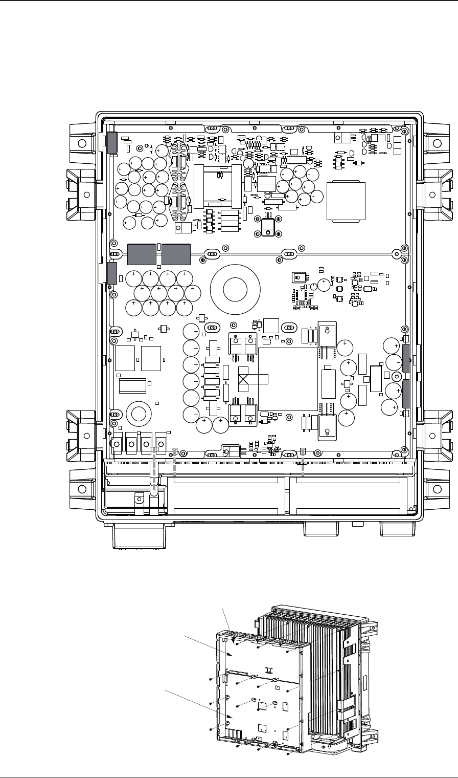
Chapter 5: Spare part exchange5-4 98-144591-A
500 W Transciver Unit
The modules and internal cables illustrated in the following pages are available as spare parts, some as
individual parts and others as part of a subassembly or a set. For identifi cation of parts and part numbers
refer to the eShop at the Thrane & Thrane Extranet.”
C20
R49
R85
L6
R38
C52
C59
R58
R22
C29
C63
R43
R52
V2
T1
R53
C9
V9
T2
V39
V35
V48
V49
V50
V51
C41
V7
C51
N4
R37
L3
C37
L1
R60
C33
C30
C35
C36
R44
C64
V45
V43
C32
C31
C34
L5
HS1
C12
C15
C10
V30
V31
R42
R59
R24
R80
R11
C18
C61
R46
R83
V27
C17
C42
C16
C11
C13
V18
R12
R6
C67
R75
R77
R19
R56
R18
R73
R69 V38
C38
V22
R74
R72
N3
R71
C68
R76
R4
C8
V26
R31
R28
R68
R30
R23
V29
R17
V36
V17
R15
R29
C5
V25
R55
V5
V24
R9
V12
R8
R34
R45
R62
N2
R70
C47
C65
V42
V44
R41
R39
V11
C57
R57 R78 V37
V46
R36
N1
C44
R67
C66
V47
R66
HS2
C62
C46
R40
V40
C14
C43
C49
R81
V6
R32
R33
R7
V21
C45
R16
R26
V28
R64
R54
N5
C58
V32
R20
D1
V1
V16 V19
R50
R65
L4
C39
C40
R14
H6
H12
H11
H7
H10
H9
V34
R51
V52
C70
R27
V15
V14
C6
C7
R84
R63
R13
C1
V23
R1
V33
C2
C3
C4
R10
R82
C55
V41
H1
X6
X7
H2 H3
H4
H5
X1
C53
C56
C60
R86
R61
R47
R25
V20
C71
R35
R48
L2
R5
R21
V4
R79
R3
R2
C69
R87
C19
V10
C54
V8
H8
V6
L9
C69
H7
C109
C110
C111
C112
C101
C102 C103 C104
C105 C106 C107 C108
C76 C78
C75
C129
C131
C130
V18
R1
L11
OLS
C4
R14
R7
R17
R8
N3
R13
V10
C2
R18
R12
V17
C8
R16
R84
R85
R86
R6
R10
R9
L10
R80
R65
R44
C12
R36
R41
R39
R37
R69
V24
C20
C11
R43
C15
R79
R82
C19
C14
C18
C38
C37
R57
R53
R56
C39
N5
V16
R24
R61
C63
C132
C121
T1
V7
C3
V36
C25
R58
R50
C23
R23
R34
C48
C60
C65
C74
R2
L8
L14
V5
V30
V1
C24
C26
C31
K1
V21
V22
K2
L1
R33
L5
C30
V15
R25
V14
L2
C124
C9
C54
V4
R11
R22
R15
R4
C1
N4
R71
N2
V20
N1
R46
C7
R48
R30
C44
V13
R35 R29
R26
R67
R32
R27
R55
V25
R73
C16
C29
C28
C27
C57
C62
C32
C47
C56
V37
R54
X10
X6X7
X5
X4
X3
X23
X22
H13
H4
H10
H9
H6
H5
H3
H11
H12
H2
H1
H8
X13X12
X11
V34
L7
C122
C123
L6
R76
C64
R77
C59
R75
C55
C13
C67
R62R63
R74
R28R66
R68
R21
V35
C5
R40
R49
R81
R42
R31
R70
V33
R52
C72
C68
C71
C6
L4
R78
C66
C61
V11
C77
V3
V19
V2
C17
R83
V9
R5
R3
R19
C58
V31
V32
V28
R51
L3
C70
H29
H30
H31
H32
H33
V12
V8
V38 V39
H20
H21
H22
H23
H19
H15
H16
H17
H18
H14
H24
H25
H26
H27
H28
L13
L12
C21
C22
H34
H36
H37
H41
H38
H39
H49
H44
H50
H51
H52
H53
H45
H46
H47
H48
H40
H42
H43
H35
99-126732
SMPS 60-126172
SMPS 60-126136
W17 W18
W19
W20
W21
W22
W23
99-126896
Loosen 15 screws M3x8
Internal SMPS
to remove SMPS chassis
PA SMPS
Transceiver Unit module location
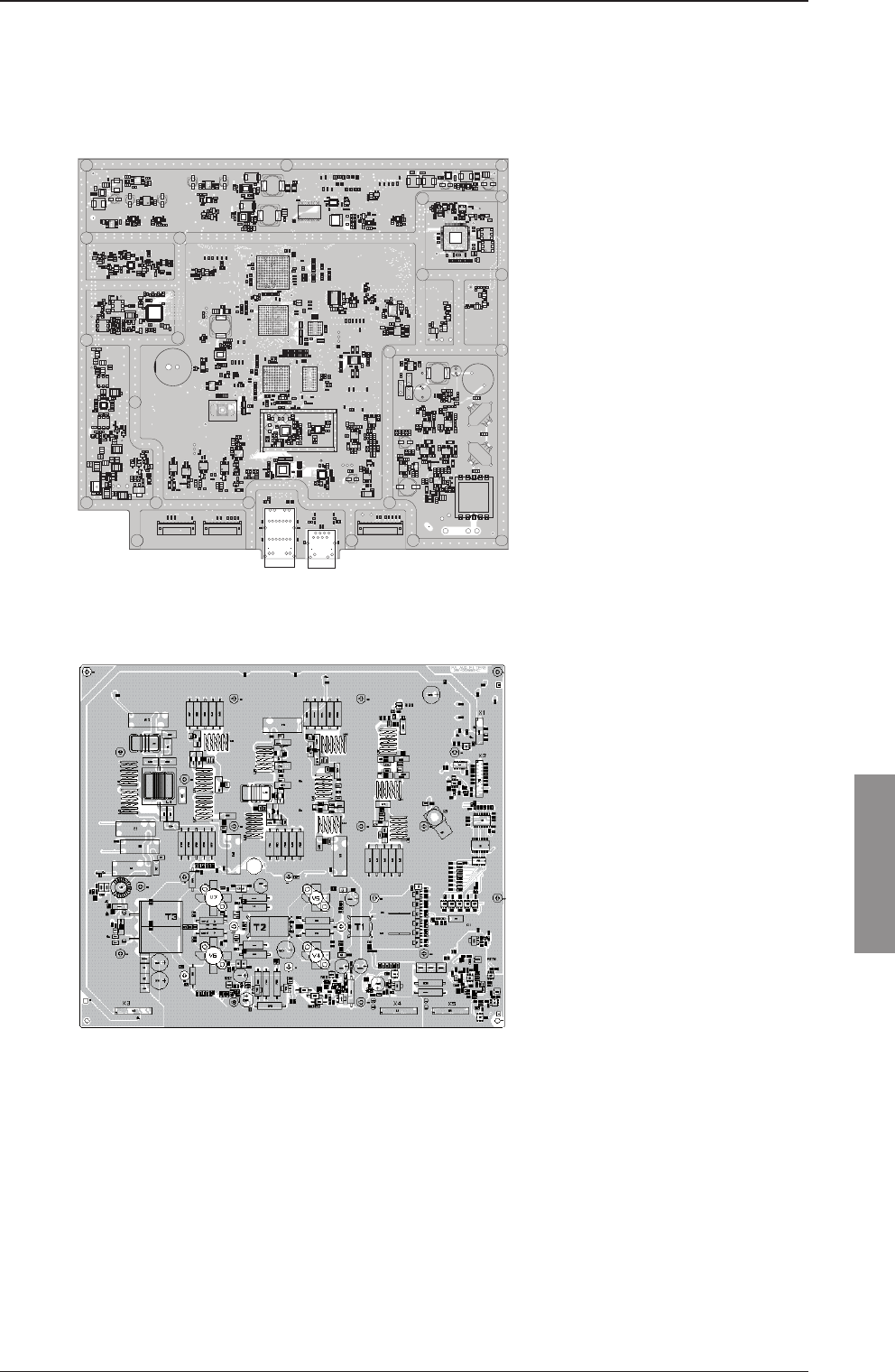
Chapter 5: Spare part exchange 5-5
Spare part exchange
98-144591-A
5.4 Module overview
Exciter Control module 60-139984
+
+
+
+
+
+
+
+
-
-
BOOT_CSn
Boot_Flash
Boot_Ctrl
L1400
L1405 L1405
L1406
L1407
L1408
L1408
L1401
L1402
U506
J505
L1305
L1304
L1303
L1300
L1301
L1301
REF
C544
Y503
R336
J500
J400
E1400
R1670
R834
R832
R424
R404
R343
R1412
R1630
R1641
R1647
R1659
R1665
R1617
R423
R1722
R1728
R1737
R1724
R803
R809
R812
R800
R808
R801
R811
R807
R802
R830
R826
R817
R1609
R1602
R1610
R1614
R1605
R1601
R815
R1325
R1322
R1323
R1734
R1616
R1671
R1675
C1541
C1555
C1399
C1398
C1830
C1829
C1828
C1827
C1826
C1310
C1341
C1537
C1600
C813
C815
C821
C840
C1447
C1456
C1476
C1483
C1445
C1454
C1461
C1477
C1489
C1498
C1343
C1345
C1344
C1352
C1411
C1416
C1417
C1412
C1409
C1418
C1419
C1413
C1410
C1420
C1421
C1405
C1422
C1415
C1414
C1430
C1442
C1432
C1433 C1434
C1435
C1436
C1437
C1438
C1439
C1431
C1441
C1440
C1626
C1646
C1648
C1650
C1651
C1620
C1632
C1641
C1530
C1469
C1466
C1473
C1459
C701
C1714
C1778
C1780
C1782
C1746
C1743
C1745
C1752
C1767
C1775
C1755
C819
C823
C838
C843
C831
C804
C807
C803
C837
C835
C1300
C1301
C1403
C1407
C1528
C1518
C1512
C827
C1329
C1328
C1803
C269
C1616
C1820
C1821
C1822
CR1400 CR1401
CR1402 CR1403
CR1601
CR1602
CR1605
CR1603
CR1604
CR1606
CR1608
CR1607
CR1609
CR1600
CR402
CR700
CR701
CR703
CR702
L1501
L1403
L1404
L1409
L1410
L1411
L1502
L1503
L1504
L1505
L1413
L1412
L1506
J1602
J401
J402
U1404
U1400
T1403
T1400
T1401
T1501
T1500
U1402
U1401
U1309
R1525
R1317
R1332
R1334
R1700
R1702
R1433
R1455
R1436
R1701
R1713
R508
R1410
R1414
R1415
R1407
R1408
R1417
R1423
R1424
R1425 R1418
R1420
R1419
R1421
R1422
R1454
R1453
R1634
R1666
R1638
R1615
R1623
R1620
R1607
R1604
R1608
R516
R1437
R1460
R1452
R1451
R1450
R1449
R1448
R702
R703
R1710
R1711
R1712
R1714
R1741
R1719
R1735
R1738
R1729
R1720
R1721
R1730
R1731
R806
R810
R342
R340
R1501
R1527
R1500
R1532
R1742
R1815
R1811
R1814
R567R567
R1912
R1911
R1910R1910
R1909R1909
R445R445
R787
R786
R566
R565
R499
R1905
R1908R1906
R1907
R1890R1890
R1363
R1206
R1205
R1204
R1160
R562
R561
R560
R559
R498
R497
R496
R495
R1619
R1676
R1017
R1016
R494
R493
R1159
R1361
R1362
R419
R420
R432
R416 R417
R431
R509R509R515R515
R1650
R1428
R1440
R1441
R1442
R1443
R1444
R1445
R1613
R837
R1200
R1201
R1307
R1813
R1812
R441
R443
R466
R532
R531
R407
R405
R352
R351
R403
R402
R325
R315
R326
R327
R328
R329
R324
R337
R347
R346
R345
R344
R330
R323
R320
R322
R321
R319
R318
R316
R200
R1122
R1116
R1116
R1115
R1115
R1114
R1114
R1113
R1113
R1121
R1121
R1120
R1120
R1119
R1119
R1118
R1118
R1101
R1102
R1104
R1103
R1125
R1339
R1353
R1351
R487
R486
R442
R447
R449
R448
R465
R464
R463
R462
R461
R460
R459
R458
R457
R456
R455
R454
R453
R452
R451
R484
R483
R482
R481
R480
R479
R477
R476
R475
R474
R473
R472
R471
R470
R450R469
R485
R468
R467
R440
R439
R437
R438
R435
R332
R335
R428
R425
R414
R410
R550
R552
R501
R500
R764
R1409
R1411
R1413
R1416
R1506
R1503
R1504
R1507
R1505
R1508
R1644
R1649
R1502
R1509
R1510
R1003
R1004
R1005
R1008
R1010
R1006 R1000
R1001
R1002
R1007
R1009
R511
R513
R510
R512
R517
R518
R526
R534
R540
R545
R521
R520
R1480
R1484
R1486
R1485
R1470
R1475
R1476
R1479
R1481
R1482
R1474
R1490R1478
R1477
R1458
R1459
R1462
R1463
R1439
R1446
R1435
R1447
R1457
R1456
R1461
R1438
R1434
R1430
R1432
R1431R1429
R1427
R1345
R1341
R1343
R1342
R1350
R1344
R1347
R1349
R1348
R1340
R1337
R1336
R602
R606
R601
R600
R603
R604
R605
R607
R400
R429
R611
R614
R401
R406
R411
R415
R418
R478
R717
R719
R721
R707
R713
R700R701
R705
R708
R714
R709
R733
R727
R734
R728
R735
R729
R730 R718
R767
R766
R770
R776
R771
R772
R778
R773
R779
R774
R780
R775
R781
R737
R739
R738
R782
R783
R1703
R1705
R1706
R1715
R1718
R1716
R1717
R1465
R1464
R1732
R1739
R1736
R1740
R1723
R1727
R1725
R1726
R818
R819
R828
R831
R835
R827
R805
R813
R804
R823
R822
R821
R824
R816
R820
R829
R825
R1310
R1306
R1304
R1305
R1311
R1309
R1318
R1315
R1314
R1327
R1324
R1335
R1333
R1321
R1329
R1326
R1331
R1328
R1316
R1312
R1313
R1526
R1521
R1520
R1528
R1522
R1523
R1524
R1529
R1531
R1530
R833
R814
R333
R527
R422
R1330
R1320
R1308
R529
R433
R331
R1511
R903
R836
R334
R1319
R1426
R1473
R1466
R1469
R1468
R1467
R1488
R1354
R1359
R1352
R1355
R1357
R1346
R1356
R1672
R1667
R1636
R1669
R1668
R1664
R1663
R1661
R1658
R1656
R1654
R1635
R1639
R1637
R1633
R1631
R1629
R1628
R1626
R1662
R1652
R1648
R1632
R1624
R1622
R1660
R1621
R1673
R1657
R1653
R1627
R1625
R1646
R1642
R1640
R1517R1518
R1519
R1496
R1358
R1360
R1471
R1483
R1489
R1472
R1495
R743
R745
R1514
R1513
R436
R1404
R1405
R1406
R1403
R1401
R1400
R1402
R1338
R300
R301
R306
R307
R310
R312
R309
R308
R1126
R1127
R1128
R1129
R1130
R1131
R1132
R1133
R1134
R1135
R1136
R1137
R1138
R1140 R1139
R1141
R1142
R1144
R1146
R1148
R1150
R1152
R1154
R1156
R1157
R1143
R1145
R1147
R1149
R1151
R1153
R1155
R1618
R542
R444
R350
R769
R768
R720
R1752
R1744
R1750R1745
R1749
R1751R1747
R1743
R1704
R1733
R349
R353
R354
R558
R536
R389
R557
R488
R489
R1818
R1819
R1820
R490
R491
R492
R535
R538
R541
R544
R555
R556
R608
R609
R610
R612
R613
R615
R616
R617
R618
R704
R710
R712
R715
R716
R722
R723
R724
R725
R726
R732
R731
R736
R740
R741
R742
R744
R746
R747
R748
R749
R750
R751
R752
R753
R754
R755
R756
R757 R758
R759
R760
R761
R762
R763
R765
R777
R784
R785
R901
R902
R905
R906
R907
R908
R909
R910
R911
R1011
R1012
R1013
R1014
R1015
R1158
R1202
R1203
R1300
R1301
R1302
R1303
R1487
R1491
R1492
R1493
R1494
R1497
R1498
R1817
R1816
R1499
R1810
R1512
R1515
R1516
U1403
C443
C1565
C1564
C1834
C1831
C1832
C1833
C1654
C812
C814
C1304
C1309
C1314
C1316
C1319
C1323
C1324
C1327
C1333
C1337
C420
C421
C422
C423
C424
C427
C1400
C1402
C1406
C1427
C1429
C1467
C1468
C1499
C1401
C1404
C1408
C1423
C1424
C1425
C1426
C1428
C1443
C1444
C530
C401
C319
C314
C313
C507
C505
C500
C1318
C1320
C1349
C1347
C545
C411
C410
C409
C408
C407
C406
C405
C310
C309
C312
C311
C321
C434
C432
C415
C414
C709
C1453
C1452
C1523
C1513
C1524
C1514
C1515
C1520
C1526
C1517
C1529
C1521
C1511
C1522
C518
C519
C526
C525
C537
C538
C510
C509
C514
C515
C536C535
C1487
C1491
C1482
C1488
C1492
C1484
C1485
C1490
C1494
C1462
C1472
C1465
C1475
C1464
C1474
C1463
C1460
C1455
C1446
C1346
C1332
C1342
C605
C603
C604
C601
C602
C612
C403
C404
C438
C437
C416
C418
C429
C428
C431
C430
C1448
C1449 C1450
C1451
C1470
C1471
C1457
C1458
C715
C716
C718
C724
C719
C720
C726
C721
C727
C722
C728
C723
C729
C710
C711
C712
C713
C714
C703
C704
C705
C706
C707
C708
C717
C1707
C1715
C1732
C1724
C1726
C1728
C1747
C1750
C1748
C1764
C1771
C1753
C1768
C1774
C1749
C1765
C1776
C1758
C1763
C1769
C1766
C1770
C1773
C1772
C832
C841
C836
C845
C842
C816
C801
C809
C805
C808
C817
C806
C811
C825
C830
C829
C828
C834
C1311
C1538
C1552
C1536
C1556
C1558
C1557
C1539
C1542
C1543
C1544
C1545
C1546 C1547
C1548
C1549
C1551
C1553
C1532
C1516
C439
C1554
C1303
C502
C1533
C1519
C1510
C1509
C1313
C1312
C1302
C1486
C1478
C1481
C1480
C1479
C1495
C1358
C1359
C1348
C1355
C1356
C1353
C1351
C1354
C1357
C1350
C1496
C1823
C1550
C1503
C1504
C1505
C1508
C1507
C1506
C1500
C1562
C1563
C1561
C1531
C300
C304
C307
C337
C305
C326
C1824
C1825
C1497
C315
C339
C340
C399
C341
C442
C520
C521
C725
C1330
U1000
U600
L1602
C412
C1637
C818
C508
C506
C320
C413
C1623
C1631
C1621
C1636
C1624
C1625
C1642
C1647
C1653
C1627
C1622
C1643
C1634
C1652
C1649
C1635
C1618
C1617
C1619
C1604
C700
C1709
C1708
C1710
C1730
C1731
C1739
C1742 C1744
C1741
C1725
C1727
C1729
C1701
C1700
C1702
C1703
C1704
C1713
C1706
C1716
C1718
C1720
C1722
C1777
C1779
C1781
C1751
C1754
C1756
C802
C800
C810
C824
C1308
C1307
C1317
C1315
C1326
C1606
C1605
C1603
C1602
C1601
C1609
C1608
C1607
C501
C822
C1525
C1340
C1331
C1325
C1322
C1321
C826
C402
C1339
C1633
C1733
C1740
L1603
L1604
C1629
C1628
C1630
C702
C833
C839
C844
C820
C1559
C1540
C1535
C1534
C1493
U1602 U1604
U1603
U1605
U1606
U1601
U401
U403
U405
N1701
N1703
N1704
U800
U800
N800
N800
U801
U1300
U1600
U304
U402
U404
U803
Q1308
Q1604 Q1603
Q400
Q1304
Q1305
Q1302
Q1300
Q1400
Q1401
Q1303
Q1701
Q1702 Q1703
L1601
C1614
L1703
L1704
L1600
L1705
C1612
C1615
C1613
RV1600
U1501
U200
U704
U701
U701
U307
R338
R339
R524
R525
R904
R912
R913
R914
R528 R530
R900
U501
Y500
Y501
E500
E600
E601
E1503
E1505
E1504
E1301
E1300
E1500
E1501
E1502
Q502
Q1405
Q1406
Q1407
Q1404
Q1403
Q1402
Q1307
Q1306
Q1306
L1302
U1405
Y1400
U601
U302
U1304
U1502
U303
U305
U602
U308
U308
U703
U400
U702
CR403
CR401
CR404
R408
R426
R430
R427
R412
R409
R421
U1706
U1700
U1700
TP1716
TP1718
TP804
TP805
TP807
TP808
TP806
TP1714
TP1719
TP1723
U705
L1700
L1701
L1702
N1700
C1305
C1336
C400
C1717
C1719
C1721
C1723
U1702
CR1700
U1704
U1704
U1703
CR1702
CR1701
U1705
U802
U500
U500
U1303
U1305
U1306
U1308
U1302
U1503
C1611
C1610
C1338
Y300
Y301
U1500
U1307
U1301
L1500
U900
Q1301
Q1601
.SK1
C224
C213
C227
C235
C236
C1655
C1757
C1760
C1761
C1762
C1759
C1306
C1335
C1334
38-139984-D
Cobham
+
-
-
+
+
+
+
+
+
+
+
+
PA and fi lters module 60-122881 (150 W/250 W)
Transceiver Unit module location
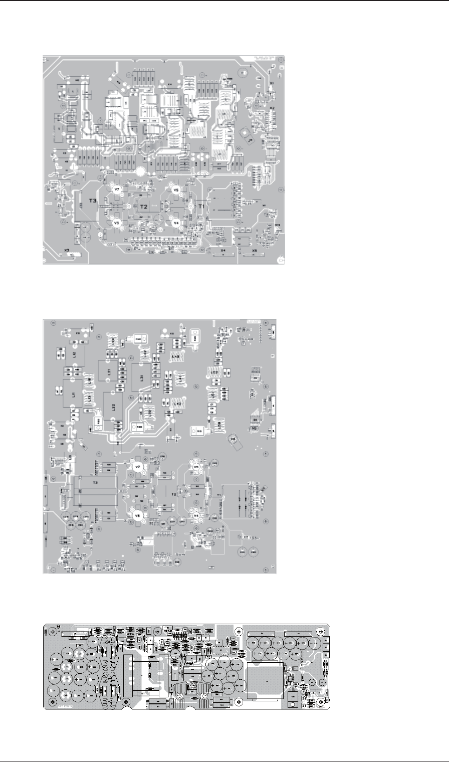
Chapter 5: Spare part exchange5-6 98-144591-A
Module overview
PA and fi lters module 60-123937 (FCC)
PA and fi lters module 60-125886 (500 W)
SMPS module 60-122882 (150 W/250 W)
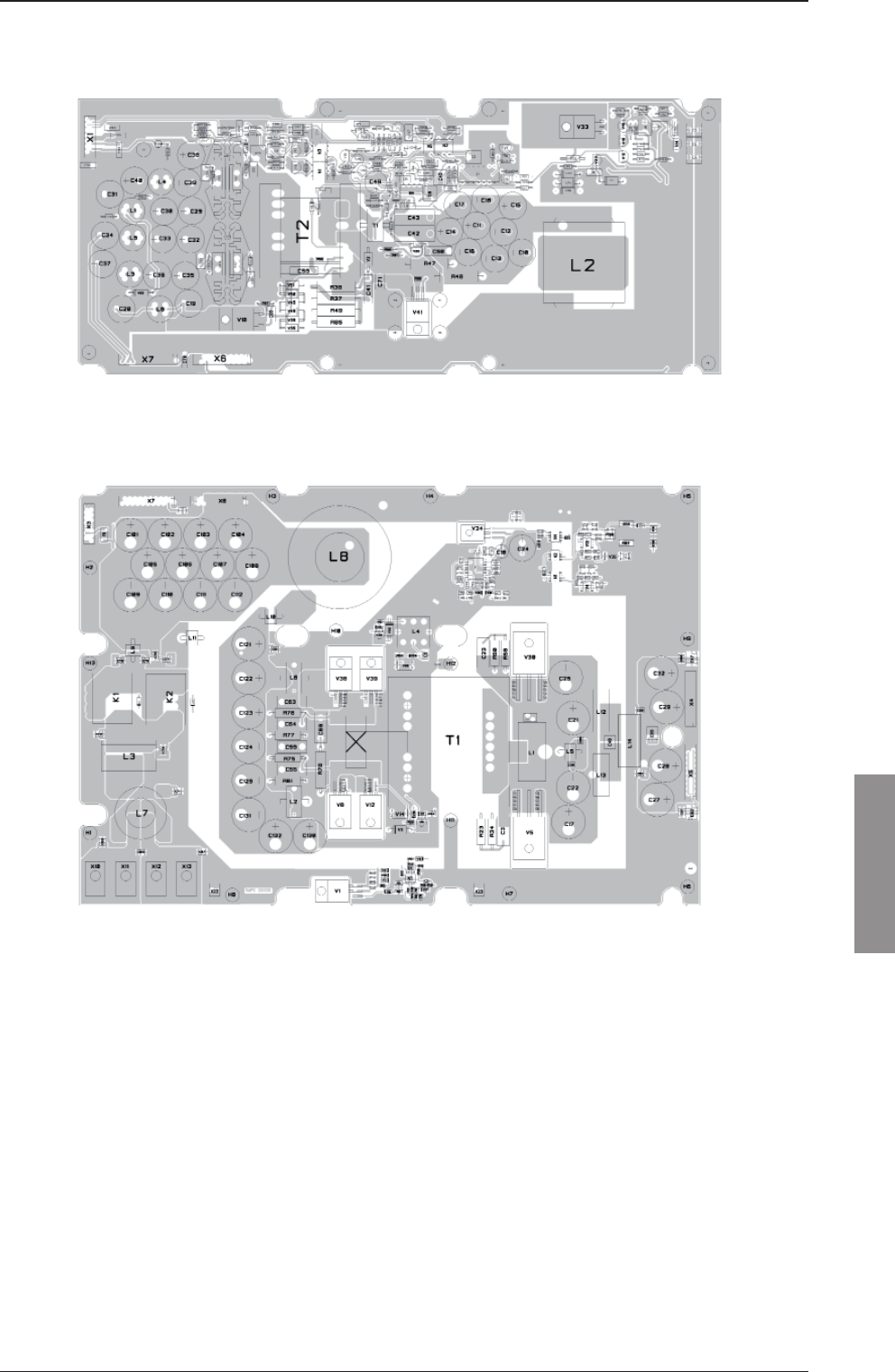
Chapter 5: Spare part exchange 5-7
Spare part exchange
98-144591-A
SMPS module 60-126172 (500 W)
SMPS module 60-126136 (500 W)
Module overview

Chapter 5: Spare part exchange5-8 98-144591-A
5.5 Required service tools
150 W/250 W
For disassembling transceiver unit: Slotted screwdriver
For shield cover, print and cables: Torx screwdriver T10
500 W
For disassembling transceiver unit: Hexagonal socket wrench 1/4" lenght min.16 cm
For transceiver modules and cables: Torx screwdriver T10
Slottet screwdriver
Spanner for M5 nut
5.6 Accessory list
Item Part no.
SAILOR 6301 Control Unit Class A 406301A
SAILOR 6365B 150 W MF/HF Transceiver Unit DSC Class A 406365B
SAILOR 6366B 150 W MF/HF Transceiver Unit DSC Class A FCC 406366B
SAILOR 6368B 250 W MF/HF Transceiver Unit DSC Class A 406368B
SAILOR 6369B 500 W MF/HF Transceiver Unit DSC Class A 406369B
SAILOR 6381 150 W/250 W Antenna Tuning Unit DSC Class A 406381A
SAILOR 6383 500 W Antenna Tuning Unit DSC Class A 406383A
SAILOR 6384B 500 W Antenna Tuning Unit DSC Class A 406384B
SAILOR 6006 Massage Terminal 406006A
SAILOR 6001 Keyboard for Message Terminal 406001A
SAILOR 6103 Multi Alarm Panel 406103A
SAILOR 6080 Power Supply 406080A
SAILOR 6081 Power Supply & Charger 406081A
SAILOR 6197 Ethernet Switch 406197A
SAILOR 6208 Control Unit Connection Box 406208A
SAILOR 6209 Accessory Connection Box 406209A
SAILOR 6270 External 8W Loudspeaker 406270A
Optional installation kit (3 x SAILOR 6080 + 1 x SAILOR 6081) 406081-004
ATU Mounting Kit
Mounting plate and fi ttings for mast 737589
Mounting plate 737588
Gasket kit for Antenna Tuning Unit 737822
Accessory list

Glossary-1
Glossary
98-144591-A
Chapter 1: General information
Glossary
A
AGC Automatic Gain Control
ALC Automatic Level Control
AM Amplitude Modulation
ATU Antenna Tuning Unit
C
CU Control Unit
D
DSC Digital Selective Call
F
FEC Forward Error Correction
H
HF High Frequency 3-30 MHz
J
J2B DSC/Telex (modulation)
J3E SSB Telephony (modulation)
L
LSB Lower Side Band
M
MF Medium Frequency 300-3000 KHz
MMSI Maritime Mobile Service Identity
MSI Maritime Safety Information
N
NBDP Narrow Band Direct Printing (Radio Telex)
NMEA National Marine Electronics Association

Glossary-2 98-144591-A
Grossary
P
PA Power Amplifi er
PTT Push To Talk
R
RX Receive(r)
S
Sitor SImplex Teletype Over Radio (Radio Telex)
SMPS Switch Mode Power Supply
SSB Single Side Band (either lower or upper)
T
TU Transmitter Unit
TX Transmit
U
USB Upper Side Band

98-144591-A
www.cobham.com/satcom