Thrane and Thrane A S 6300B Sailor 6366 TU MF/HF 150W DSC Class A FCC User Manual Installation guide
Thrane & Thrane A/S Sailor 6366 TU MF/HF 150W DSC Class A FCC Installation guide
Contents
- 1. User manual
- 2. Installation guide
- 3. Installation manual
- 4. Service interface manual
Installation guide
Installation guide
SAILOR 6300 MF/HF Transceiver Unit
& Antenna Tuning Unit 150/250/500W
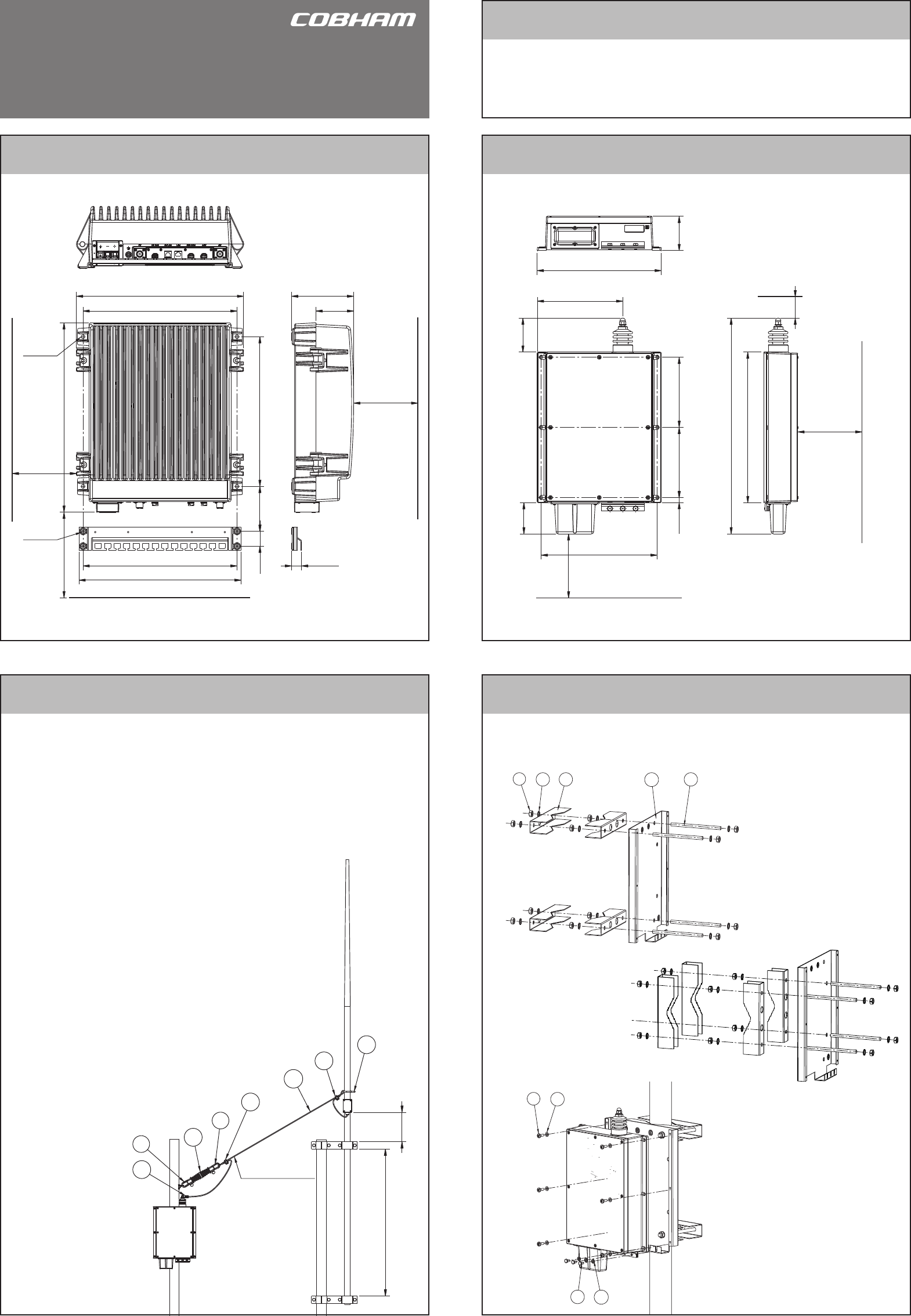
How to connect the antenna
How to install the Antenna Tuning Unit mounting bracket
How to install the Transceiver Unit 150/250W
1. Nut M10
2. Tooth lock washer M10
3. Fitting for mast
4. Mountingplate for ATU
5. Treadrod M10
Disclaimer
105 mm 350 mm
360 mm
391 mm
35 mm
150 mmMin.
379 mm
150 mmMin.
360 mm
Space for
cable access
Space for
service
4 x ø8mm
443 mm
4 x ø6mm
23.5 mm
88 mm
145 mm
500Min. mm
Space for airflow
and service
Any responsibility or liability for loss or damage in connection with the use of this product and the accompanying
documentation is disclaimed by Thrane & Thrane. The information in this manual is provided for information purposes
only, is subject to change without notice and may contain errors or inaccuracies. Manuals issued by Thrane & Thrane
are periodically revised and updated. Anyone relying on this information should acquire the most current version e.g.
from cobham.com/satcom or from the distributor. Thrane & Thrane is not responsible for the content or accuracy of
any translations or reproductions, in whole or in part, of this manual from any other source.
Thrane & Thrane A/S trading as Cobham SATCOM.
12
34
13 5
4
2
1. Pan head screw M6x16 mm
2. Washer M6
3. Hexagon head screw M6x10 mm
4. Flat washer ø6.4xø12x1.6 mm
How to install the Antenna Tuning Unit 150/250W
Space for cable and
service access
164 mm 164 mm
271 mm
150Min. mm
75 mm
12 mm
80 mm
200 mm
352 mm
504 mm
500Min. mm
50Min. mm
Space for
service access
Space to nearest overhang
80 mm
290 mm
1000 mm
200 mm
4
2
1
1
3
3
5
6Wire length 4 metres
Optional accessories:
Mounting plate and ttings for mast part no 737589.
Mounting plate only - part no 737588.
Cable fitting
In general a 12 metres antenna installation is preferred and can be made using an 8
metres whip and 4.5 metres feeder or a 10 metres whip and 2.5 metres feeder. In both
cases the whip should be mounted on a pole providing sufcient height to have the
Antenna Tuning Unit mounted such that it allows for the feeder to be erected at an
angle of 45 to 60 degrees, creating a combined 12 metres vertical antenna system.
The feeder wire is terminated at the antenna horn at the top of the Antenna Tuning
Unit. Use a supporting insulator near the ATU to carry mechanical stress from the
feeder wire. Use a short exible part of the feeder wire between the supporting
insulator and the ATU horn in order not to ap-
ply mechanical stress to the antenna horn.
To maximize the radiated power and avoid ash
over, keep distance to metal parts as long as
possible, preferable more than 100 mm. Use a
short direct ground connection from the ground
clamp at the bottom end at the Antenna Tuning
Unit to nearest suitable metal ground plane.
It is recommended to use the ATU mounting
bracket for the physical tting of the ATU.
For further information, download the installation
manual 98-144591 at www.cobham/satcom.
Optional accessories:
Antenna connection kit
part no 405301A-905.
1. Shackle
2. Isolator
3. Wire clamp
4. Wire
5. Cable tie
6. Wire lug
98-144542-A.01
www.cobham.com/satcom
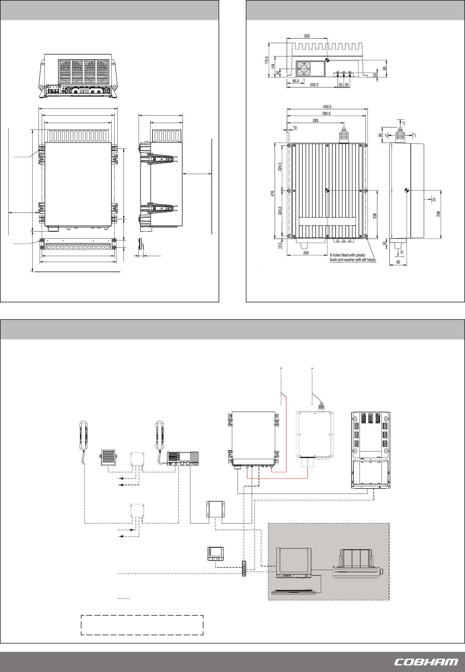
How to install the Antenna Tuning Unit 500W
System conguration - Example
1. Distance to metal constructions: min. 150
2. Space for service access: min. 500
3. Space for cable and service access: min. 200
Dimensions are in mm
For further information, download the installation
manual 98-144591 at www.cobham/satcom
How to install the Transceiver Unit 500W
360 mm
379 mm
35 mm 105 mm 350 mm
150 mmMin.
200 mmMin.
360 mm
391 mm
332 mm
505 mm
Space for cable
and airflow
Space for
service access
Cable fitting
4 x ø8mm
4 x ø6mm
1000Min. mm
160 mm
217 mm
23.5 mm
Space for airflow
and service
TT-6209A
Accessory
Connection Box
TT-6209A
Accessory
Connection Box
Unit
Antenna Tuning
Tx
Handset
TT-638xB
Message Terminal
DSC Watch receiver
250W MF/HF with 6 ch. Scanning
TT-636xB
(Optional)
Keyboard
MF/HF Control Unit
TT-630xA
Alarm Panel
TT- 6103A
Ethernet Switch
TT-6197A
Handset
GPS option
2182 select option
TT-6270A
Power Supply
TT-608xA
Connection Box
Control Unit
Distress Alarm
Other Alarm
TT-6201A
Transceiver Unit
TT-6201A
TT-6208A
TT-6001A
TT- 6006A
(Optional)
Rx
GPS on LAN option
Optional connection
Telex option
Printer
H1252B