Thrane and Thrane A S 6300B Sailor 6366 TU MF/HF 150W DSC Class A FCC User Manual S6000B MFHF Service Interface Manual 03
Thrane & Thrane A/S Sailor 6366 TU MF/HF 150W DSC Class A FCC S6000B MFHF Service Interface Manual 03
Contents
- 1. User manual
- 2. Installation guide
- 3. Installation manual
- 4. Service interface manual
Service interface manual
SAILOR 6300B MF/HF Service Interface
User Manual
Document number: 97-147768-A
Release Date: 31 August 2015

97-147768-A SAILOR 6300B MF/HF Service Interface User Manual
2
Disclaimer
Any responsibility or liability for loss or damage in connection with the use of this product and the accompanying
documentation is disclaimed by Thrane & Thrane A/S. The information in this manual is provided for information
purposes only, is subject to change without notice and may contain errors or inaccuracies. Manuals issued by
Thrane & Thrane A/S are periodically revised and updated. Anyone relying on this information should acquire the
most current version e.g. from http://www.cobham.com/communications-and-connectivity/satcom, Service and
support, or from the distributor. Thrane & Thrane A/S is not responsible for the content or accuracy of any
translations or reproductions, in whole or in part, of this manual from any other source. In the event of any
discrepancies, the English version shall be the governing text.
Thrane & Thrane A/S is trading as Cobham SATCOM.
Copyright
© 2015 Thrane & Thrane A/S. All rights reserved.
Record of revisions
Rev.
Description
Release Date
Initials
A
Initial
August 2015
JTR
A
Review Comments from BLN, DAV, CMA, RSH,
JKR, TOP and JHO August 2015 JHO
A
Comments from CMA+TOP
August 2015
JHO

97-147768-A SAILOR 6300B MF/HF Service Interface User Manual
3
Table of contents
1 Introduction .................................................................................................................... 4
1.1 Precautions using the service tool ........................................................................................... 4
2 Connecting to the service tool ........................................................................................... 4
2.1 Connecting to the service without a network .......................................................................... 4
2.2 Connecting to the service tool through a network................................................................... 4
3 Overview of functionality ................................................................................................. 6
3.1 Open access functionality ....................................................................................................... 6
3.1.1 STATUS .............................................................................................................................. 6
3.1.2 LOGS .................................................................................................................................. 8
3.1.3 NMEA ................................................................................................................................. 8
3.2 Protected access functionality ................................................................................................ 9
3.2.1 CHANNELS ........................................................................................................................ 10
3.2.2 CONFIG .......................................................................................................................... 12
3.2.3 TOOLS ............................................................................................................................... 17

97-147768-A SAILOR 6300B MF/HF Service Interface User Manual
4
1 Introduction
The service tool for the S6000 radio series MF/HF devices is made available by a built-in
web server in the radio. The service tool can be accessed from a computer connected to a
LAN shared with the device and is displayed in an internet browser with no additional
installation of software required. Currently we do not guarantee full support for
Microsoft Internet Explorer, but most HTML5 enabled browsers are supported.
Screenshots in this manual were done using Google Chrome.
1.1 Precautions using the service tool
WARNING: While using the service tool the network cable should not be removed
or disconnected from neither the PC nor the radio.
WARNING: While using the service tool, power to the radio should not be switched off.
Violation of the precautions above can result in a defect radio, which only
can be repaired by the manufacturer.
WARNING: The Service agent is responsible for all changes made with the service tool.
Changes must be in conformance with radio specifications and regulations.
2 Connecting to the service tool
2.1 Connecting to the service without a network
The service tool for the radio can be accessed directly without use of a network, by use of
a PC with automatic network configuration and an internet browser. Connect the radio
to the computer using the Ethernet interface and type the IP address of the radio in the
address field of an internet browser to access the service tool. This will open the radio
status page of the service tool and the radio can now be configured. The radio’s current
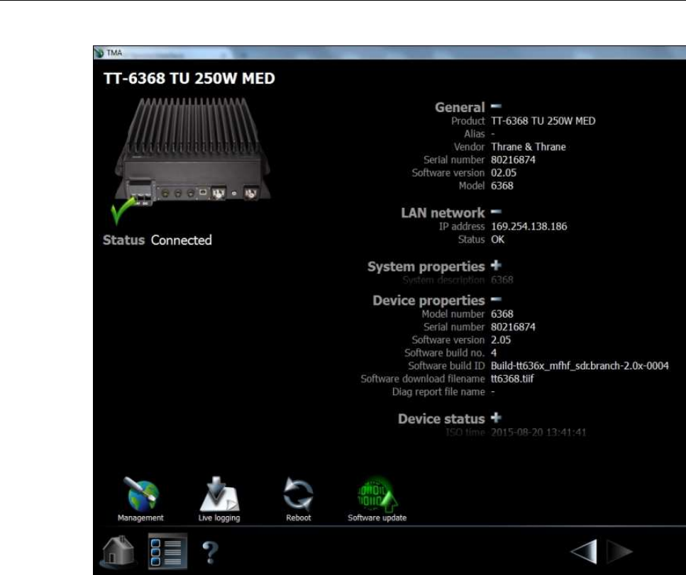
IP address is visible in the SYSTEM SETUP menu on the radio control unit or in the
radio’s entry in the TMA tool as seen in Figure 1 below.
2.2 Connecting to the service tool through a network
The service tool can be accessed through a LAN from a PC with an internet browser.
Type the IP address of the radio in the address field of an internet browser to access the
service tool. This will open the radio status page of the service tool and the radio can now
be configured. The radio’s current IP address is visible in the SYSTEM SETUP menu on
the radio control unit or in the radio’s entry in the TMA tool as seen in Figure 1 below.
97-147768-A SAILOR 6300B MF/HF Service Interface User Manual
5
Figure 1: TMA tool page for the radio displaying IP address, etc.
97-147768-A SAILOR 6300B MF/HF Service Interface User Manual
6
3 Overview of functionality
The service tool is used to perform updates to the firmware and various settings of the
radio. This section describes each feature of the service tool in turn. The tool will show
information about firmware, status of the radio and data from the logs for all users
without administrator rights, covered in section 3.1. For administrators the service tool
provides functionality for configuration of radio settings and tools for administration of
firmware, covered in section 3.2.
3.1 Open access functionality
The open access information of the service tool is divided into three tab pages, described
in the following three subsections.
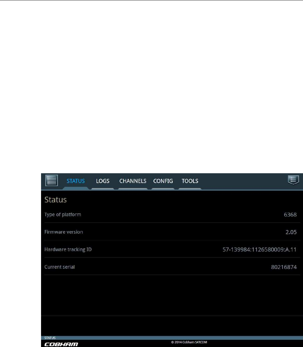
3.1.1 STATUS
The STATUS tab page can be seen below in Figure 2.
Figure 2: Status tab.
The status tab is used to show the current platform and hardware configuration of the
radio. The field Hardware tracking ID is used in service of the transceiver unit.
97-147768-A SAILOR 6300B MF/HF Service Interface User Manual
7
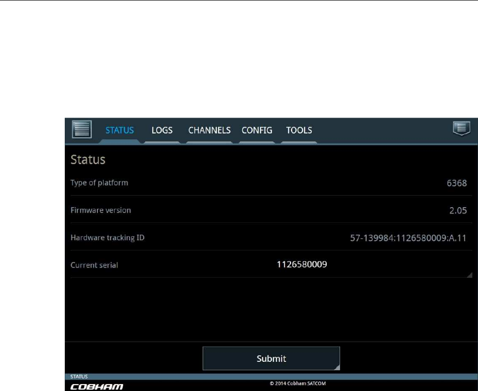
If the main board of the radio is replaced, a new serial number can be applied in the
Current serial field. When no serial number is programmed, the ‘current serial’ field will
display a 10-digit tracking number. This means that it is possible to input the serial
number of the system .
Note: updating the serial number can only performed one time and that updating the
field requires logging in (described in section 3.2).
97-147768-A SAILOR 6300B MF/HF Service Interface User Manual
8
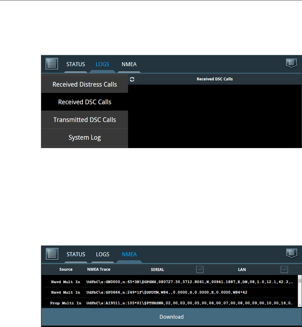
3.1.2 LOGS
The LOGS tab can be seen in Figure 3 below.
Figure 3: LOGS tab.
This tab includes four side-bar buttons, where each displays the respective logs over
Received Distress Calls, Received DSC Calls, Transmitted DSC Calls and one button for
the System Log. Each log can be downloaded as a .tar.gz file.
3.1.3 NMEA
The NMEA tab pane displays a stream of NMEA data collected over SERIAL and/or LAN.
The data can be downloaded as a compressed file of the format .tar.gz and will contain
more lines than displayed on the screen. See example printout in Figure 4 below.
Figure 4: NMEA tab.
Note: Several tools are capable of unpacking tar.gz files, including 7zip, Winrar,
Winzip, etc.
97-147768-A SAILOR 6300B MF/HF Service Interface User Manual
9
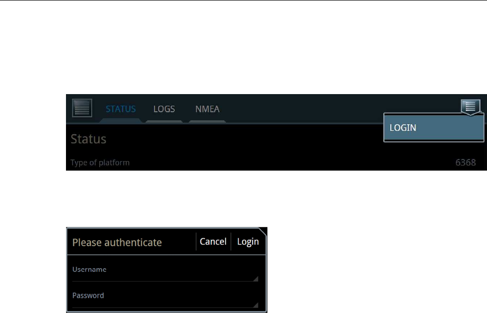
3.2 Protected access functionality
Protected administrator access to the service tool is obtained by logging in using the
button in the upper right corner of the service tool (see Figure 5 below).
Figure 5: Login button.
By pressing the LOGIN button a pop-up will show.
Figure 6: Login pop-up.
To get administrator access enter the following into the two fields:
• Username: admin
• Password: sailorsailor
When logged in to the protected part of the service tool the radio is disabled and the tab
pages CHANNELS, CONFIG and TOOLS become accessible. These tabs are described in
the following sub sections.
97-147768-A SAILOR 6300B MF/HF Service Interface User Manual
10
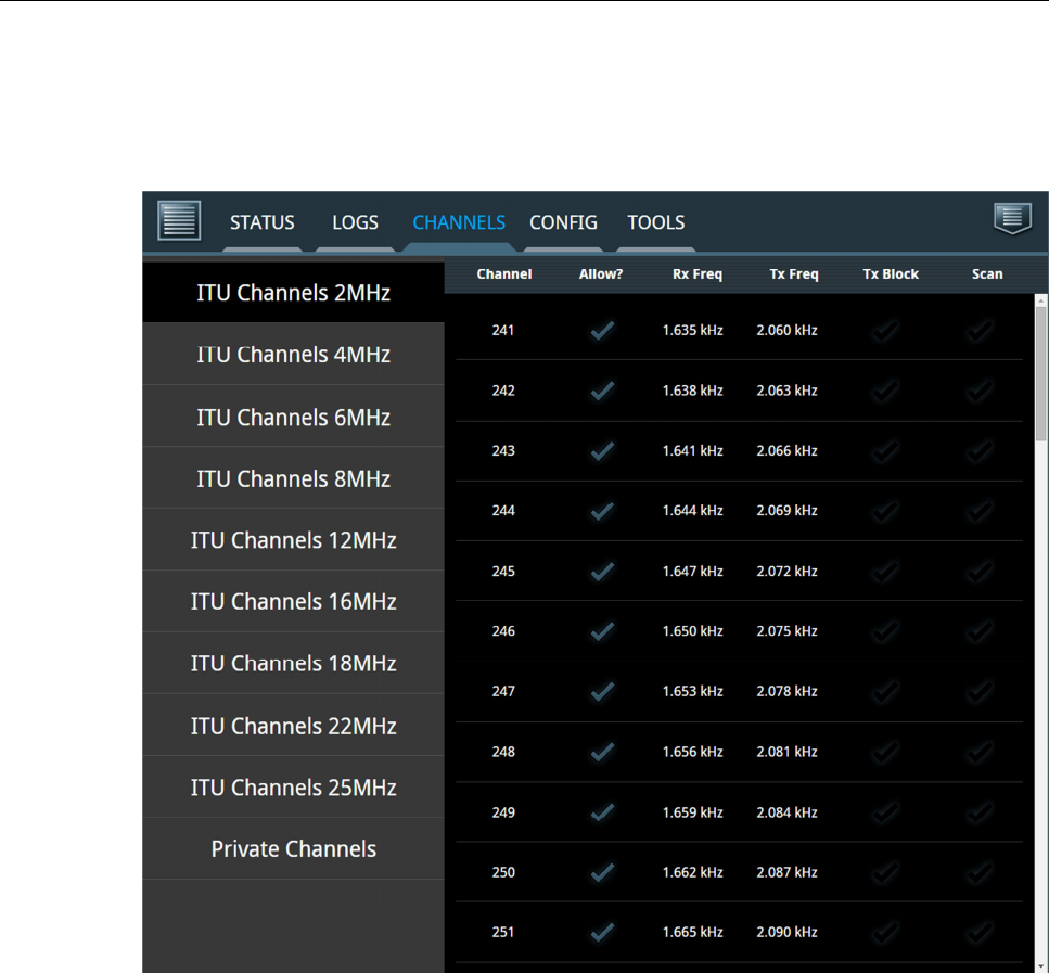
3.2.1 CHANNELS
An example of the CHANNELS tab can be seen in Figure 7 below.
Figure 7: CHANNELS tab.
This tab has a side-bar button for various ITU channel bands and for private channels.
The user must click on a channel row on the page to select a channel for configuration.
When selecting channel 241 the following configuration page for the channel appears
(Figure 8):
97-147768-A SAILOR 6300B MF/HF Service Interface User Manual
11
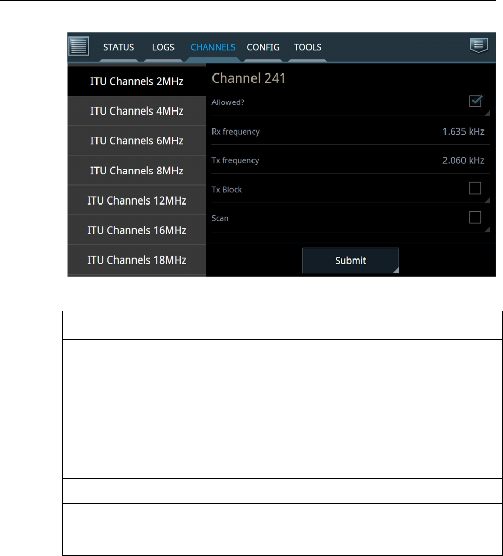
Figure 8: Configuration of Channel 241.
Channel settings
Description
Allowed
?
Select this tag to show the channel in the channel table and make it
available via the control unit.
Remove the tag to remove the channel from the channel table and
from the control unit. This can also be done for channels which are
normally included from the factory (ITU channels).
R
X
frequency
Specify receive frequency.
T
X
frequency
Specify transmission frequency.
T
X
Block
Select this tag in order to block transmitting on this channel.
Scan
Select this tag to include this
specific channel in the scanning table.
Note that tagging all channels to be scanned will increase the time
between scanning each separate channel.
To configure the channel fill in the respective fields and click the Submit button.

97-147768-A SAILOR 6300B MF/HF Service Interface User Manual
12
3.2.2 CONFIG
The CONFIG tab contains two side-bar buttons and each are described in turn:
Figure 9: CONFIG tab – Configuration side-bar page.
Configuration
Description
MMSI
Enter or change the MMSI number of the radio.
Call ID or MMSI
This is the 5
-
digit Telex call id. If
there is no 5
-
digit call id
allocated you can use the 9-digit MMSI or leave the field empty.
Abbreviated ID
This is used for Telex identification and is part of the answer
back string. The abbreviated ID is usually 4 ASCII letters, e.g.
‘abcd’.
Slave
delay
This is the slave
delay used during Telex ARQ calls.
Default value
is 10.
ATU available?
Des
elect this tag if the system
does not have
an ATU (Antenna
Tuning Unit) connected. The option is used for dedicated
antenna on specific frequency or dummy load.
Note: Wrong selection may damage the ATU.
PSU Monitor
enabled
If the radio’s power supply is a SAILOR 6081 you can enable the
Power Supply Monitor in the radio.
Primary
station
Select this tag if you want this radio to have priority over a
duplicate MF/HF installation.

97-147768-A SAILOR 6300B MF/HF Service Interface User Manual
13
The MMSI, Call-id and abbreviated ID are used to construct the telex answer back string.
The rule for creating a valid answerback string is:
• Figure shift
• Carriage return
• Line feed
• 9-digit MMSI (or 5-digit call ID)
• Letter shift
• Space
• Abbreviated ID
• Space
• X
• Letter shifts to bring the total length up to 20 characters
The service tool will automatically add the figure shifts, letter shifts, spaces and the letter
‘x’ where appropriate. It is strongly recommended to check the telex settings on the
SAILOR 6006 Message Terminal (Telex) when the settings above have been modified
and the radio has been power cycled.
97-147768-A SAILOR 6300B MF/HF Service Interface User Manual
14
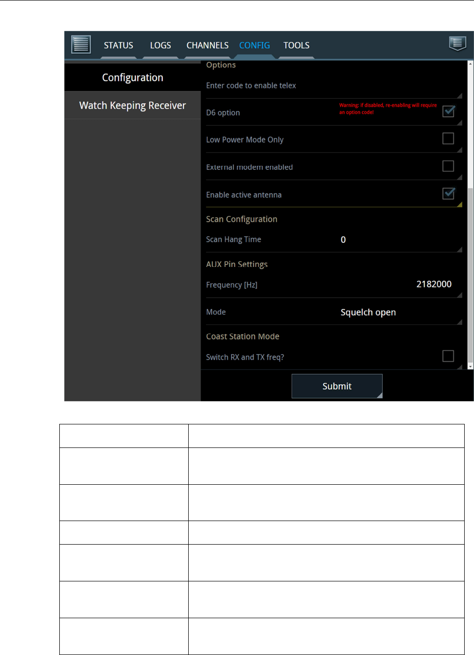
Figure 10: CONFIG tab – Configuration side-bar page continued.
Options
Description
Enter code to enable telex
Enter the
option
code to enable telex.
After entering, the
option can be removed again by de-checking the check box
D6 option
De
-
select
check box
to disable D6
(6 channel watch keeping
receiver). To re-enable, input the option code.
Low Power Mode Only
Transmit is only allowed at low output power.
External modem enabled
If the radio is used in connection with external modem
,
enable this option to achieve correct power output.
Enable active antenna
Check this option to enable s
upply current for active
antenna (12VDC max 60mA).
Scan hang time
H
ang time, in seconds
, to wait on a channel with signal,
before resuming the scan.

97-147768-A SAILOR 6300B MF/HF Service Interface User Manual
15
*) As for telex, the user must enter the code delivered with the system to enable D6. The
field D6 option in Figure 10 above depicts how the field appears when the activation code
has already been entered to the field. Before deselecting options, the service tool issues
a warning (see Figure 10, D6 option for example).
AUX Pin Settings:
Frequency [Hz]
Select the frequency for which the AUX pin is active.
Mode
Choose between Off, Squelch open (as in
Figure 10
) or On
Channel.
Coast Station Mode:
Switch RX and TX freq?
Swaps duplex frequencies
when used as a ship counterpart.
Also GPS alarms and leading 00 in MMSI are allowed.
When all desired configurations are entered to the fields, click Submit.
97-147768-A SAILOR 6300B MF/HF Service Interface User Manual
16
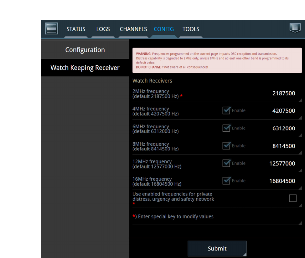
Figure 11: CONFIG tab – Watch Keeping Receiver side-bar button.
On the Watch Keeping Receiver page it is possible to program 6 DSC frequencies into
the watch receiver or disable frequencies. These custom frequencies will also be available
for routine DSC transmissions. If the programmed frequencies are required for a custom
distress network (for distress, safety and urgency calls), the following option key is
required:
ABCD-1234-COBH-2014
WARNING: changing these frequencies WILL alter the ability to send and receive
distress to/from established GMDSS coast stations. Non-default programming of the
2MHz frequency also needs the special options key as this will void MF-DSC capability.
WARNING: HF DSC functionality requires watch receiver option, enabled scanning on at
least 2MHz band, 8MHz band and at least one other band.
Click Submit when desired configuration has been reached.
97-147768-A SAILOR 6300B MF/HF Service Interface User Manual
17
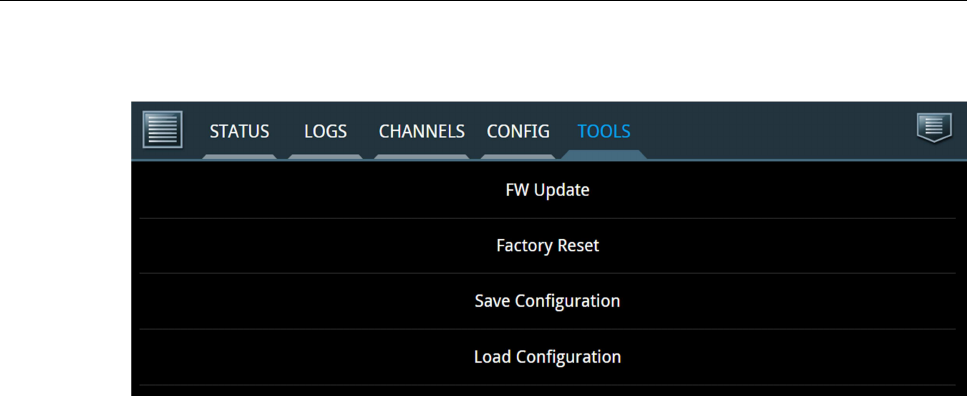
3.2.3 TOOLS
Figure 12: TOOLS tab.
• The FW Update button lets the operator upload new firmware to the radio. Only
files issued by Cobham shall be used in the .tiif format.
• The Factory Reset button can be used if the operator wants to return to the
default configuration of the radio. This means removing all settings in the
channel tables, configurations, MMSI etc. Option codes for radio telex and watch
keeping receiver will not be affected.
• Save Configuration downloads a .tar.gz file with all configurations done to the
radio through the service tool.
• Load Configuration is used to load configurations from a .tar.gz file made
previously on the current radio or another similar radio.
3.3 Logout
Access the option menu in the upper right corner and choose to log out to do so. Upon
logging out, the radio will reboot utilizing the new settings and be ready for normal
operation.