Topcon America F90901 GNSS Receiver with 900 MHz and Bluetooth Radio User Manual GR 5 OM
Topcon America Corporation GNSS Receiver with 900 MHz and Bluetooth Radio GR 5 OM
Contents
- 1. User Manual
- 2. Op Manual
Op Manual


GR-5
Featuring Vanguard Technology
Operator’s Manual
PartNumber7010‐1004
RevE
©CopyrightTopconPositioningSystems,Inc.
May,2018
AllcontentsinthismanualarecopyrightedbyTopconPositioningSystems,Inc.Allrightsreserved.

• • • • • •
Table of Contents
i
P/N:7010‐1004
Preface........................................................................ ix
TermsandConditions................................................................... ix
Use.............................................................................. ix
Copyrights ........................................................................ x
Trademarks ....................................................................... x
DisclaimerofWarranty.............................................................. x
LicenseAgreement................................................................. xi
Confidentiality ..................................................................... xi
Website;OtherStatements.......................................................... xii
Safety............................................................................ xii
Miscellaneous ..................................................................... xii
ManualConventions ................................................................ xiii
Introduction ................................................................... 1
ii
P/N:7010‐1004
GR‐5Features ......................................................................... 2
UnpackingYourReceiverKit ............................................................. 3
StandardKitComponents1.......................................................... 3
Accessories ....................................................................... 4
TechnicalDocuments................................................................... 5
UsingTopconSoftwareWithYourReceiver ................................................. 5
GettingTechnicalSupport............................................................... 6
Website .......................................................................... 7
GettingAcquainted.............................................................. 8
ReceiverOverview ..................................................................... 8
Cables................................................................................ 9
Accessories ........................................................................... 11
Batteries.............................................................................. 13
DataandPowerPorts................................................................... 14
ExternalRadioAntennaConnector ........................................................ 15
BottomConnector ..................................................................... 16
SD/SDHCandSIMCardSlots............................................................. 17
iii
P/N:7010‐1004
SIMCardSlot ...................................................................... 18
SIMCards ..................................................................... 18
InstallingtheSIMCard ........................................................... 18
DisplayPanelOperations ......................................................... 19
PowerButton ......................................................................... 20
ReceiverStatusLEDs.................................................................... 20
STATLED ......................................................................... 21
RECLED .......................................................................... 21
RXTXLED ......................................................................... 22
BluetoothLED ..................................................................... 24
BatteryLED ........................................................................... 24
FUNCTIONButton/LoggingData.......................................................... 26
ManagingPower................................................................ 30
TurningOn/OfftheReceiver ............................................................. 30
PoweringtheReceiver.................................................................. 30
DetachableExternalBatteries........................................................ 31
ChargingtheBatteries ........................................................... 31
iv
P/N:7010‐1004
BatteryChargingTemperatures................................................... 34
ChargingProcedure............................................................. 34
LeavingtheBatteriesonCharge ................................................... 36
AttachingtheBatteries .......................................................... 36
DetachingtheBatteries .......................................................... 37
AssemblingtheAABatteryShell................................................... 37
SurveyingWhileCharging ........................................................ 38
ChangingtheBatterieswhileSurveying ............................................. 39
UsinganAuxiliaryPowerSource...................................................... 39
InsufficientPower ...................................................................... 42
ConfiguringtheReceiver ......................................................... 43
ViewingReceiverInformation............................................................ 43
LoadingNewFirmware.................................................................. 45
AbouttheOAF......................................................................... 49
CheckingtheReceiver’sOAF ......................................................... 49
LoadinganOAF.................................................................... 50
PerformingaFactoryReset.............................................................. 53
FieldSystemSetup.............................................................. 55
v
P/N:7010‐1004
SettingUptheBaseReceiver ............................................................. 55
SettingUptheRoverReceiver ............................................................ 56
MeasuringAntennaHeight .............................................................. 57
CollectingData ................................................................. 59
Memory .............................................................................. 59
SD/SDHCCard..................................................................... 60
InstallingtheSD/SDHCCard ...................................................... 60
InitializingtheFileSystem ........................................................... 61
InitializingtheFileSystemUsingTRU............................................... 61
SettingRecordingParameters ............................................................ 62
LoggingRates.......................................................................... 62
RecordingData ........................................................................ 62
ManagingFiles......................................................................... 64
DownloadingandDeletingFiles....................................................... 64
Troubleshooting................................................................ 65
CheckThisFirst! ....................................................................... 65
PoweringProblems..................................................................... 66
vi
P/N:7010‐1004
ReceiverProblems ..................................................................... 67
BluetoothProblems .................................................................... 71
TRUProblems ......................................................................... 73
CleaningandStoringtheReceiver......................................................... 74
GettingCustomerSupport ............................................................... 74
Specifications .................................................................. 75
GeneralDetails ........................................................................ 75
DUHFIIInternalModemBoardDetails(Optional)............................................ 87
FH915InternalModemBoardDetails..................................................... 88
OptionalCellModuleDetails ............................................................. 90
BluetoothModuleDetails ............................................................... 93
ConnectorSpecifications................................................................ 93
Radio(Modem)RFConnector........................................................ 94
PowerConnector................................................................... 95
SerialC‐RS232Connector ............................................................ 96
USBConnector..................................................................... 98
Brazil‐OnlyRadioSpecifications........................................................... 99
vii
P/N:7010‐1004
ProductIdentification............................................................ 102
SD/SDHCCardRecommendations.................................................. 103
SafetyWarnings ................................................................ 104
GeneralWarnings ...................................................................... 104
BatteryWarnings ...................................................................... 105
ReceiverWarnings ..................................................................... 106
UsageWarnings....................................................................... 106
Regulatory ..................................................................... 107
FCCCompliance........................................................................ 107
IndustryCanadaCompliance ............................................................. 108
ICRFRadiationExposureStatement ................................................... 110
ICAdditionalStatementwithDetachableAntennas...................................... 111
CommunityofEuropeCompliance........................................................ 112
EuropeanCommunityDeclarationofConformitywithR&TTEDirective1999/5/EC ............ 112
DeclarationofConformity(R&TTEDirective1999/5/EC)...................................... 115
BrazilAnatelCompliance................................................................ 118
WEEEDirective ........................................................................ 119
viii
P/N:7010‐1004
BluetoothTransmissionStatements/Compliance............................................ 119
Warranty ...................................................................... 120
Glossary ....................................................................... 121

Preface
ix
P/N:7010‐1004
• • • • • •
Preface
ThankyouforpurchasingthisTopconproduct.ThematerialsavailableinthisManual(the“Manual”)havebeenpreparedby
TopconPositioningSystems,Inc.(“TPS”)forownersofTopconproducts,andaredesignedtoassistownerswiththeuseofthe
receiveranditsuseissubjecttothesetermsandconditions(the“TermsandConditions”).
Terms and Conditions
Use
Thisproductisdesignedtobeusedbyaprofessional.Theusershouldhaveagoodknowledgeofthesafeuseoftheproductand
implementthetypesofsafetyproceduresrecommendedbythelocalgovernmentprotectionagencyforbothprivateuseand
commercialjobsites.
Pleasereadthetermsandconditionscarefully.

Preface
TermsandConditions
x
P/N:7010‐1004
Copyrights
AllinformationcontainedinthisManualistheintellectualpropertyof,andcopyrightedmaterialofTPS.Allrightsarereserved.
Donotuse,access,copy,store,display,createderivativeworksof,sell,modify,publish,distribute,orallowanythirdpartyaccess
to,anygraphics,content,informationordatainthisManualwithoutTPS’expresswrittenconsentandmayonlyusesuch
informationforthecareandoperationofthereceiver.TheinformationanddatainthisManualareavaluableassetofTPSand
aredevelopedbytheexpenditureofconsiderablework,timeandmoney,andaretheresultoforiginalselection,coordination
andarrangementbyTPS.
Trademarks
GR‐5,VanguardTechnology™,FenceAntenna™Technology,TRU™,Magnet™,Pocket‐3D™,Topcon®andTopconPositioning
Systems™aretrademarksorregisteredtrademarksofTPS.Windows®isaregisteredtrademarkofMicrosoftCorporation.The
Bluetooth®wordmarkandlogosareownedbyBluetoothSIG,Inc.andanyuseofsuchmarksbyTopconPositioningSystems,
Inc.isusedunderlicense.Otherproductandcompanynamesmentionedhereinmaybetrademarksoftheirrespectiveowners.
Disclaimer of Warranty
EXCEPTFORANYWARRANTIESINANAPPENDIXORAWARRANTYCARDACCOMPANYINGTHEPRODUCT,THISMANUALAND
THERECEIVERAREPROVIDED“AS‐IS.”THEREARENOOTHERWARRANTIES.TPSDISCLAIMSANYIMPLIEDWARRANTYOF
MERCHANTABILITYORFITNESSFORANYPARTICULARUSEORPURPOSE.TPSANDITSDISTRIBUTORSSHALLNOTBELIABLEFOR
TECHNICALOREDITORIALERRORSOROMISSIONSCONTAINEDHEREIN;NORFORINCIDENTALORCONSEQUENTIALDAMAGES
RESULTINGFROMTHEFURNISHING,PERFORMANCEORUSEOFTHISMATERIALORTHERECEIVER.SUCHDISCLAIMED
DAMAGESINCLUDEBUTARENOTLIMITEDTOLOSSOFTIME,LOSSORDESTRUCTIONOFDATA,LOSSOFPROFIT,SAVINGSOR
REVENUE,ORLOSSOFTHEPRODUCT’SUSE.INADDITIONTPSISNOTRESPONSIBLEORLIABLEFORDAMAGESORCOSTS

Preface
TermsandConditions
xi
P/N:7010‐1004
INCURREDINCONNECTIONWITHOBTAININGSUBSTITUTEPRODUCTSORSOFTWARE,CLAIMSBYOTHERS,INCONVENIENCE,OR
ANYOTHERCOSTS.INANYEVENT,TPSSHALLHAVENOLIABILITYFORDAMAGESOROTHERWISETOYOUORANYOTHER
PERSONORENTITYINEXCESSOFTHEPURCHASEPRICEFORTHERECEIVER.
License Agreement
UseofanycomputerprogramsorsoftwaresuppliedbyTPSordownloadedfromaTPSwebsite(the“Software”)inconnection
withthereceiverconstitutesacceptanceoftheseTermsandConditionsinthisManualandanagreementtoabidebythese
TermsandConditions.Theuserisgrantedapersonal,non‐exclusive,non‐transferablelicensetousesuchSoftwareunderthe
termsstatedhereinandinanycaseonlywithasinglereceiverorsinglecomputer.YoumaynotassignortransfertheSoftware
orthislicensewithouttheexpresswrittenconsentofTPS.Thislicenseiseffectiveuntilterminated.Youmayterminatethe
licenseatanytimebydestroyingtheSoftwareandManual.TPSmayterminatethelicenseifyoufailtocomplywithanyofthe
TermsorConditions.YouagreetodestroytheSoftwareandmanualuponterminationoftheuseofthereceiver.Allownership,
copyrightandotherintellectualpropertyrightsinandtotheSoftwarebelongtoTPS.Iftheselicensetermsarenotacceptable,
returnanyunusedsoftwareandmanual.
Confidentiality
ThisManual,itscontentsandtheSoftware(collectively,the“ConfidentialInformation”)aretheconfidentialandproprietary
informationofTPS.YouagreetotreatTPS’ConfidentialInformationwithadegreeofcarenolessstringentthatthedegreeof
careyouwoulduseinsafeguardingyourownmostvaluabletradesecrets.Nothinginthisparagraphshallrestrictyoufrom
disclosingConfidentialInformationtoyouremployeesasmaybenecessaryorappropriatetooperateorcareforthereceiver.
SuchemployeesmustalsokeeptheConfidentialityInformationconfidential.Intheeventyoubecomelegallycompelledto
discloseanyoftheConfidentialInformation,youshallgiveTPSimmediatenoticesothatitmayseekaprotectiveorderorother
appropriateremedy.

Preface
TermsandConditions
xii
P/N:7010‐1004
Website; Other Statements
NostatementcontainedattheTPSwebsite(oranyotherwebsite)orinanyotheradvertisementsorTPSliteratureormadeby
anemployeeorindependentcontractorofTPSmodifiestheseTermsandConditions(includingtheSoftwarelicense,warranty
andlimitationofliability).
Safety
Improperuseofthereceivercanleadtoinjurytopersonsorpropertyand/ormalfunctionoftheproduct.Thereceivershould
onlyberepairedbyauthorizedTPSwarrantyservicecenters.
Miscellaneous
TheaboveTermsandConditionsmaybeamended,modified,superseded,orcanceled,atanytimebyTPS.TheaboveTermsand
Conditionswillbegovernedby,andconstruedinaccordancewith,thelawsoftheStateofCalifornia,withoutreferenceto
conflictoflaws.

Preface
TermsandConditions
xiii
P/N:7010‐1004
Manual Conventions
Thismanualusesthefollowingconventions:
Convention Description Example
Bold Menu,ordrop‐downmenuselection FileExit(ClicktheFilemenuandclickExit)
Nameofadialogboxorscreen FromtheConnectionscreen...
Buttonorkeycommands ClickFinish.
Mono Usersuppliedtextorvariable Typeguest,andclickEnter.
Italic Referencetoanothermanualorhelpdocument RefertotheTopconReferenceManual.
Furtherinformationtonoteaboutsystemconfiguration,maintenance,orsetup.
Supplementaryinformationthatcanhaveanadverseaffectonsystemoperation,systemperformance,data
integrity,measurements,orpersonalsafety.
Notificationthatanactionhasthepotentialtoresultinsystemdamage,lossofdata,lossofwarranty,or
personalinjury.

Introduction
1
P/N:7010‐1004
• • • • • •
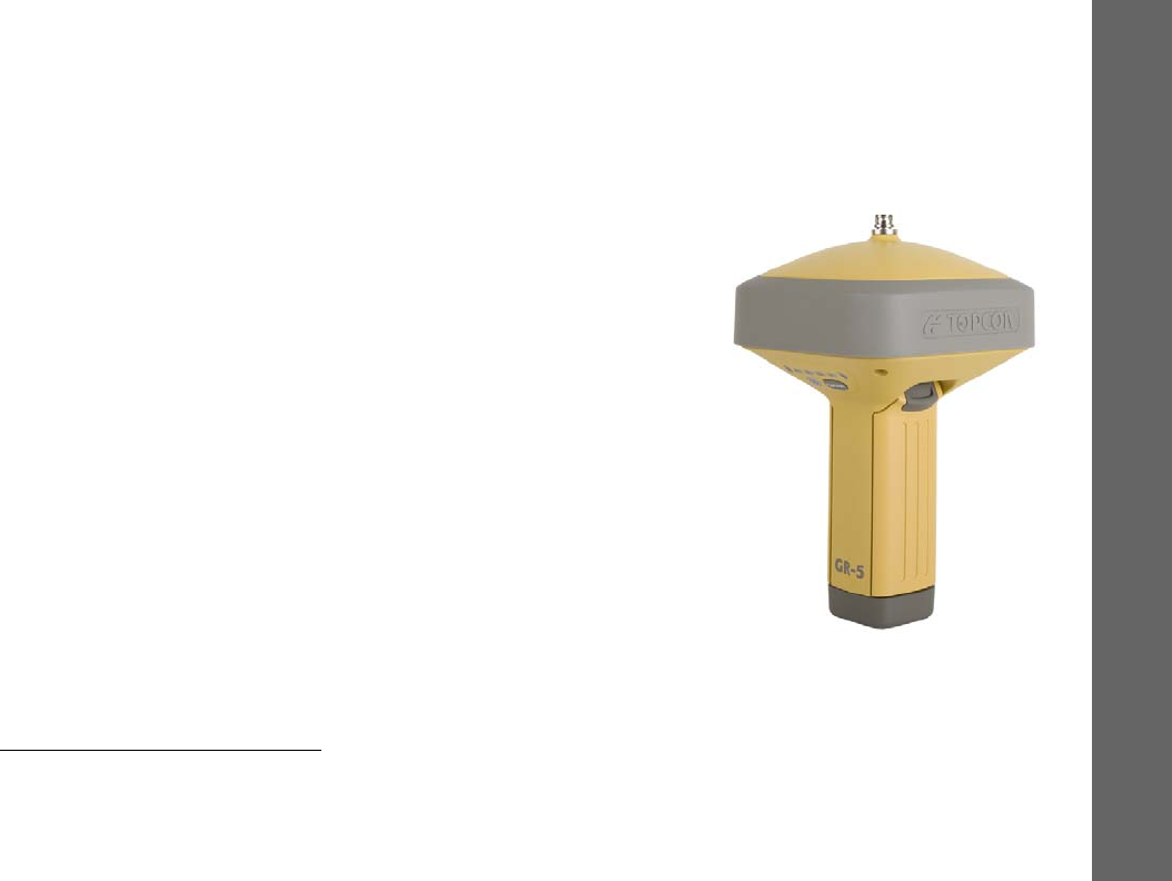
Introduction
Topcon’sGR‐5receiverisacompactandhigh‐performingGNSSreceiverforstaticandkinematicapplications.Thereceiverdesign
includesaGNSSreceiverboardbasedonVanguardTechnology™,whichprovidesunlimitedtrackingability.TheGR‐5delivers
world‐classpositioningandnavigationcapabilitytoyourapplicationbytrackingsignalswithmultiplefrequenciesandmulti‐
constellationsatellitesystems.
Usingfull‐waveFenceAntenna™Technology,theGR‐5canreceiveandprocessmultiplesignaltypes,includingthelatestGPSL2C
andL5,andotherfuture
1
signals.TheGR‐5receiverincludesanenhancedGNSSreceiverboardfeaturingVanguardTechnology
thatsupports226channels
2
.
GNSStrackingcapabilities,dual‐frequencyRTK,SBASfunctionality,extensivecommunicationcapabilities,removablememoryfor
filescombinetoprovideapositioningsystemefficient,secure,andappropriateforanysurvey.
Severaluniquefeatures,includingadvancedmultipathmitigation,adjustablePhase‐LockedLoop(LLP)andDelay‐LockedLoop
(DLL),offerareliableandversatilereceptionofweaksignalsevenindegradedsignalenvironments.Thereceiveralsosupports
QuartzLockedLook™(QLL)forsuperiorGNSStrackinginhigh‐vibrationenvironments.
TheGR‐5offerscompleteIP66protectionagainstdustandwateringress,inadditiontosuperiorvibrationandshockresistance.
TheTopconcommunicationinterfaceallowsyoutoquicklyintegrateTopcon’spremiumGNSSperformancewithinnewsystems
andquicklydeliverworld‐classpositioningandnavigationsupporttoyourapplications.
1.TheGR‐5receiver,equippedwithaGNSSboardfeaturingVanguardtechnology,isaGalileo‐andBeiDou‐readysystem.Fullsupportofthesenew
constellation(s)andassociatedsignalswillbeincorporatedintothereceiverwhentheseconstellationsarematureandreadyforcommercial
use.
2.EarlierversionsoftheGR‐5werebuiltwithPIIASIC‐basedGNSSboardsandsupported216universaltrackingchannels.See“Product
Identification”onpage102foralistofnewGR‐5receiversbuiltwithVanguardtechnology‐basedGNSSreceiverboards.
Introduction
GR‐5Features
2
P/N:7010‐1004
GR-5 Features
TheGR‐5receiver’sadvanceddesignallowsforasimplifiedsetupandpremiumperformance.TheGR‐5receiverfeaturesthe
following:
•
Apremiermulti‐constellationVanguardtechnologyGNSSboard
•
Industryleadingfull‐waveFenceAntennatechnology
•
Detachablebatteriesforextendedoperation
•
Internalradioandcellular(optional)modems
•
IntegratedBluetooth®wirelessandradiotechnology
•
OptionalHSPA(3.5G)
1
andCDMAcellulartechnology
•
InterfaceforcontrollingviewingdataloggingthroughtheLEDdisplay
•
Externalpower,USB,andserial‐dataports
•
Externalhigh‐capacitymemorycardsupport
TheGR‐5comesinoneofthefollowingconfigurations:
•
FH915+radiomodem
•
FH915+radiomodemwithHSPAmodule
•
DigitalUHFIIradiomodem
•
DigitalUHFIIradiomodemwithHSPAmodule
•
DigitalUHFIIradiomodemandCDMAmodule(USonly)
1.High‐SpeedPacketAccess(HSPA)cellularmodulesupportsfasterdatarateandisbackwardcompatiblewithGPRS/EDGE(GSM)technology.
Introduction
UnpackingYourReceiverKit
3
P/N:7010‐1004
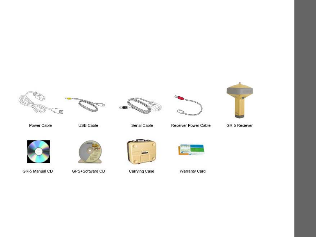
Unpacking Your Receiver Kit
Thissectiondescribesthedocumentation,standardkitcomponents
1
,andaccessories(dependingonyourpurchase)that
accompanyyourreceiver.Whenyouunpackyourreceiverkit,verifyyoureceivedtheitemslistedinthissection.Ifanyitems
aremissingordamaged,contactyourTopcondealerorTopcontechnicalsupport.See“GettingTechnicalSupport”onpage6.
Standard Kit Components1
Figure1:StandardSystemComponentsthatareIncludedwithYourReceiver
1.Componentsinstandardkitsmaydifferbasedonyourregion.ContactyourlocalTopcondealertoinquireaboutitemsincludedinyour
regionalstandardkitandaccessoriesthatareavailablewiththereceiver.
Introduction
UnpackingYourReceiverKit
4
P/N:7010‐1004
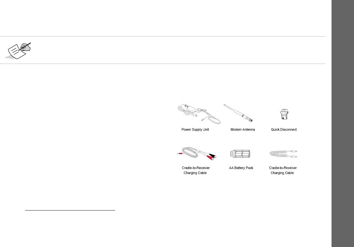
Accessories
Topconoffersawidevarietyofaccessories
1
(seeFigure2)
speciallydesignedtoimprovesystemflexibilityandjobsite
efficiency.Formoredetailsontheoptionalaccessories
availableforGR‐5,contactyourTopcondealer.
Figure2:ReceiverAccessories
TheGPS+SoftwareCDincludesUSBdrivers,whichyouneedtoinstalltousetheUSBportfor
communications.
1.Formoredetailedinformation,see“Accessories”onpage4.

Introduction
TechnicalDocuments
5
P/N:7010‐1004
Technical Documents
TheGR‐5ManualCDincludestwomanuals(listedbelow)thathelpyousetupanduseyournewreceiverquicklyandefficiently.
•
GR‐5Operator’sManual–Anon‐screenhelpdocumentthatcontainsdetailedinformationonhowtouseyournew
receiver.
•
TopconReceiverUtility(TRU)OnlineHelp–Anon‐screenhelpdocumentembeddedinthesoftwarethatcontains
detailedinformationonhowtousetheTRUsoftware.FormoreinformationabouttheTRUsoftware,see“UsingTopcon
SoftwareWithYourReceiver”.
Using Topcon Software With Your Receiver
UsetheGR‐5receiverinconjunctionwiththeTopconReceiverUtility(TRU)andMAGNETField™orPocket‐3Dapplicationsfor
aprecisionpositioningsolution.Topconsoftwareenablesyoutoconfigurethereceiverandotherexternaldevices,managefiles,
collectdata,andperformsurveyandconstructionworkflows.
TheTopconReceiverUtility(TRU)isahardwareconfigurationsoftwareforreceiversandperipheraldevices.Youcaninstalliton
desktopcomputersanddatacontrollers.ThisprogramisprovidedontheGPS+SoftwareCDthataccompaniedyourreceiver.A
TRUhelpdocumentisprovidedontheGR‐5CD.
Topcon’sMAGNETField™softwarefordatacontrollersprovidesreal‐timecommunication,cloudstorage,datacollectionand
exchange,andfieldsolutions,suchastopo,staking,roads,calculations,andmore.
Pocket‐3DisaprogramthatrunsondatacontrollerswithWindowsCE®andmobileplatforms.Pocket‐3Dsimplifiesdata
collection,allowingyoutocheckcutsandfills,layoutpointsandsurveyallorpartofthejobsitequicklyandefficiently.Contact
yourTopcondealerformoreinformationaboutTopconfielddatacollectionsoftwareforthesurveyingandconstruction
markets.

Introduction
GettingTechnicalSupport
6
P/N:7010‐1004
Getting Technical Support
BeforecontactingaTopconcustomerrepresentativeaboutanyproblemswiththereceiver,see“Troubleshooting”onpage65
forsomesolutionsthatmayfixtheissue.
ContactyourlocalTopcondealerorvisitthemyTopconWebsite(https://www.topconpositioning.com/support)fortechnical
support.
WhencontactingTopconfortechnicalassistance,providethefollowinginformationforbetterandfasterservice:
1. Adescriptionofthefollowing:
–Fieldoperationthatwasbeingperformedwhentheproblemoccurred
–Detailsoftheunexpectedbehavior,symptoms,andanyerrormessagesthatprecedeorfollowtheproblem
–Problemoccurrencefrequencyorpatterns
2. Receiverinformationandconfigurationsettings.Forreceiverinformation,clickInformationinTRU,selectSaveto
File,enterafilename,andsaveittothecomputer.
3. Specificationsofmobiledevicesandcomputersusedinthefieldorofficeexhibitingtheproblem.These
specificationsshouldincludemodelinformation,versionnumber,operatingsysteminformation,memoryand
storagecapacity,etc.
4. Informationaboutthesystemsoftware,includingtheversionnumberandstepstoreproducetheproblem.
5. Adescriptionofthefieldenvironmentand/orobservationconditionswhentheproblemoccurred.
Forquickandeffectivesupport,provideadetaileddescriptionoftheproblem.

Introduction
GettingTechnicalSupport
7
P/N:7010‐1004
Website
TheTopconwebsiteprovidescurrentinformationaboutTopcon’slineofproducts.Thesupportareaofthewebsiteprovides
accesstoTopconfieldandofficesoftware,manuals,frequentlyaskedquestions,andsoforth.ToaccesstheTopconwebsite,
visitwww.topconpositioning.com.
ThemyTopconWebsitealsoprovidescompletesupport,suchasnews,updates,reminders,training,liveWebinars,and
customerservicetohelpyougettheinformationyouneed.Visithttps://www.topconpositioning.com/support.

GettingAcquainted
8
P/N:7010‐1004
• • • • • •
Getting Acquainted
TheGR‐5receiverenclosureisfullysealedandincorporatestheGNSSreceiverboard,antenna,batteries,memorystorage,
andwirelesscommunicationdevice.
Receiver Overview
TheupperportionofthereceivercontainstheGNSSantenna,whichisenclosedbytheradomeandsecurelysurroundedby
ashock‐absorbingrubberbumper.Thereceiver’smagnesiumalloylowerenclosurefeaturesaneasy‐to‐operatedisplay
panel,detachablebatteries,quickreleasemountingsocket,anddataports.
TheGR‐5receiverhasahighly‐visibledisplaypanelwithsingle‐buttonoperation.Thedisplaypanelenablesyoutoviewthe
receiver’soperationalstatus.Formoreinformation,see“DisplayPanelOperations”onpage19.
Youcanlocateregulatoryandproductidentificationinformationonthetworeceiverlabels,whicharelocatedinsideofthe
batterycompartments.Theproductidentificationlabelcontainstheserialnumberandpartnumber.
Getting Acquainted
Cables
9
P/N:7010‐1004
Cables
TheGR‐51packageincludesapowersupplycable,aUSBcable,andapoweradapter.Table1describesthecablesincluded
withyourreceiver,dependingonyourregionalstandardkitconfiguration.MakesuretocontactyourlocalTopcondealer
toinquireaboutstandarditemsincludedinyourreceiverkit.
1.Componentsinstandardkitsmaydifferbasedonyourregion.ContactyourlocalTopcondealertoinquireaboutitemsincludedinyourregional
standardkitandaccessoriesthatareavailablewiththereceiver.
Alignthekeywayswhenconnectingthepower/serialcabletothereceiverport.Turnthecablelockclockwise
untilitclickstosecurethecableinplace.Todisconnectthecable,turnthelockcounter‐clockwise,andthen
gentlyremovethecable.
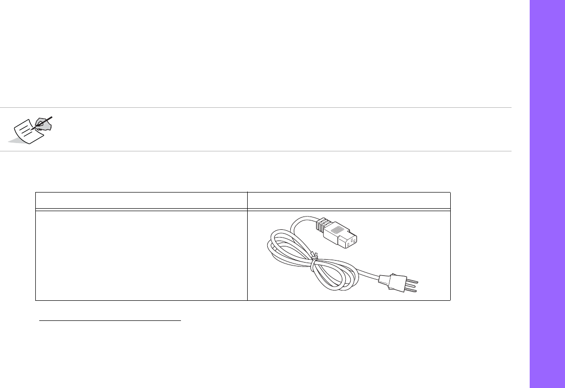
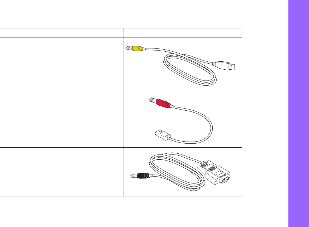
Table1.ReceiverCables
Cable Description Cable Illustration
PowerCable
Connectsthepowersupplyunittoagroundedoutlet.
U.S.:p/n:14‐008052‐01
Europe:p/n:14‐008054‐01
Australia:p/n:14‐008053‐01
Brazil:p/n:1000475‐01
Getting Acquainted
Cables
10
P/N:7010‐1004
USBCable
Connectsthereceivertoanexternaldevice(controlleror
computer)fordatatransferandreceiverconfiguration.
p/n14‐008070‐01
ReceiverPower/ChargingCable
ConnectsthereceiverandthepowersupplyunitviaSAE
connectorsforbatterycharging.
p/n14‐008016‐03
SerialCable
Connectsthereceivertoanexternaldevice(controlleror
computer)fordatatransferandreceiverconfiguration.
p/n:14‐008005‐03
Table1.ReceiverCables
Cable Description Cable Illustration

Getting Acquainted
Accessories
11
P/N:7010‐1004
Accessories
Topconoffersawidevarietyofaccessoriesspeciallydesignedtoimprovesystemflexibilityandjobsiteefficiency.Formore
detailsabouttheavailableaccessories,contactyourTopcondealer.
•
PowerSupplyUnit
(p/n22‐034101‐01):chargesthedetachablebatterieswhenconnectedtoagroundedoutlet.This
unitconvertsthealternatingcurrent(AC)normallysuppliedfromanelectricaloutlettoadirectcurrent(DC)usedto
chargethebatteriesand/orpowerthereceiver.
Thepowersupplyunitcaneitherbeconnectedtothechargingcradleordirectlytothereceiver.Fordetails,seethe
powerrelatedsectionsin“PowerSupplyUnit”onpage31.
•
TheModemAntenna
:TheSpreadSpectrum(FH915+)antennaisareversepolarityTNCRFconnection(p/n30‐030012‐
01)andaUHFantennaisaBNCconnection(p/n30‐070003‐01UHF410‐440orp/n30‐050503‐01UHF450‐470).
•
The2mFixedHeightTripodandPole
:Aheavydutytripod(22‐050501‐01).
•
Theuniversaltribrachandtribrachadapter
1
(p/n22‐006008‐01andp/n22‐006009‐011):areusedtolevelthetripod
andsecurethereceiverorantennatothetripod.
•
Theprecisiontribrachadapter
:isusedtopreciselycenter,align,andlevelthetripodoverapoint.Thehorizontalspacer
(p/n60419)insertsintotheprecisiontribrachandallowsthereceivertositsecurelyontheprecisiontribrach.
Thepowersupplyunitshouldonlybeusedforchargingthebatteries.Donotuseasapowersource
duringsurveying.
1.Theuniversaltribrachandtribrachadapterisnotneededwhenusingtheheavydutytripod(22‐050501‐01).

Getting Acquainted
Accessories
12
P/N:7010‐1004
•
Thequickdisconnectadapter
(p/n02‐850905‐01):connectstotherangepoleforthereceivertoslipintothetop.Using
thesideclips,thereceivercanbequicklyconnectedto/disconnectedfromtherangepole.
•
Ahand‐heldcontroller
:allowstheGR‐5BaseandRoversystemstobeconfiguredandmonitoreddirectlyinthefield.
YoucanusetheTopconReceiverUtility(TRU)toconfigurethereceiverandanyTopconfielddatacollectionsoftware.
•
MAGNETandPocket3DSoftware
:canbeusedtooperatethereceiver.SeereferencemanualofTRUorFielddata
collectionsoftwarefordetailsonsetupandoperation.
•
TheODU‐to‐alligatorclipscable
(p/n14‐008097‐01LF):connectsthechargingcradleorreceivertoanauxiliarybattery
forpoweringthereceiverduringsurveyoperations.
•
TheAAbatterypack
:holdsfourAAbatteriestoprovideaportablebackuppowersourceforthereceiver.Dueto
variancesinAAbatterycapacity,andthemodeofthereceiverandtypeofmodem,theamountoftimethereceiveris
poweredvaries.
•
Cradle‐to‐receiverchargingcable
(p/n14‐008072‐01(1.5mlong)p/n14‐008072‐02(0.5mlong):Connectsthereceiver
tothechargingcradleforexternalpower.
•
BatteryRecharger
(01‐050911‐01):Chargesthebatteries.See“ChargingtheBatteries”onpage31.
DonotuserechargeableAAbatteries.
DonotusetheAAbatteryshellwhentheradiomodemisintransmittermode.

Getting Acquainted
Batteries
13
P/N:7010‐1004
Batteries
Thereceivercomesequippedwithtwodetachable,rechargeablebatteriesforpoweringthereceiver.Formore
informationaboutusingthebatteries,see“ManagingPower”onpage30.
Figure3:GR‐5DetachableBatteries
Detachable
Battery
Detachable
Battery
Getting Acquainted
DataandPowerPorts
14
P/N:7010‐1004
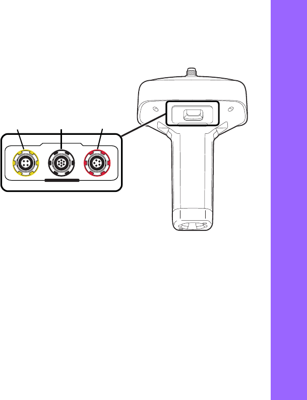
Data and Power Ports
TheGR‐5hasthefollowingthreeports:
•
USB
–rimmedinyellow;usedforhigh‐speeddata
transferandcommunicationbetweenthereceiver
andanexternaldevice.Thebodyoftheconnector
onthecorrespondingcableisyellow.
•
SerialPort
–rimmedinblack;usedfor
communicationbetweenthereceiverandan
externaldevice.
•
Power
–rimmedinred;usedtoconnectthe
receivertoanexternalpowersource.Thisportcan
alsobeusedtochargethebatteries.Thebodyof
theconnectoronthecorrespondingcableisred.
U
S
B
S
E
R
I
A
L
P
O
W
E
R
USB
(yellow)
Power
(red)
Serial
(black)
Getting Acquainted
ExternalRadioAntennaConnector
15
P/N:7010‐1004
External Radio Antenna Connector
TheradioantennaconnectstotheexternalantennaconnectorontheGR‐5radome(Figure4).Theradioantennausesa
reversepolarityTNCorBNCconnectiondependingontheinstalledradiomodem.
Figure4:GR‐5RadomeandExternalAntennaConnector
External
Antenna
Connector
Getting Acquainted
BottomConnector
16
P/N:7010‐1004
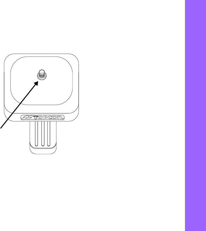
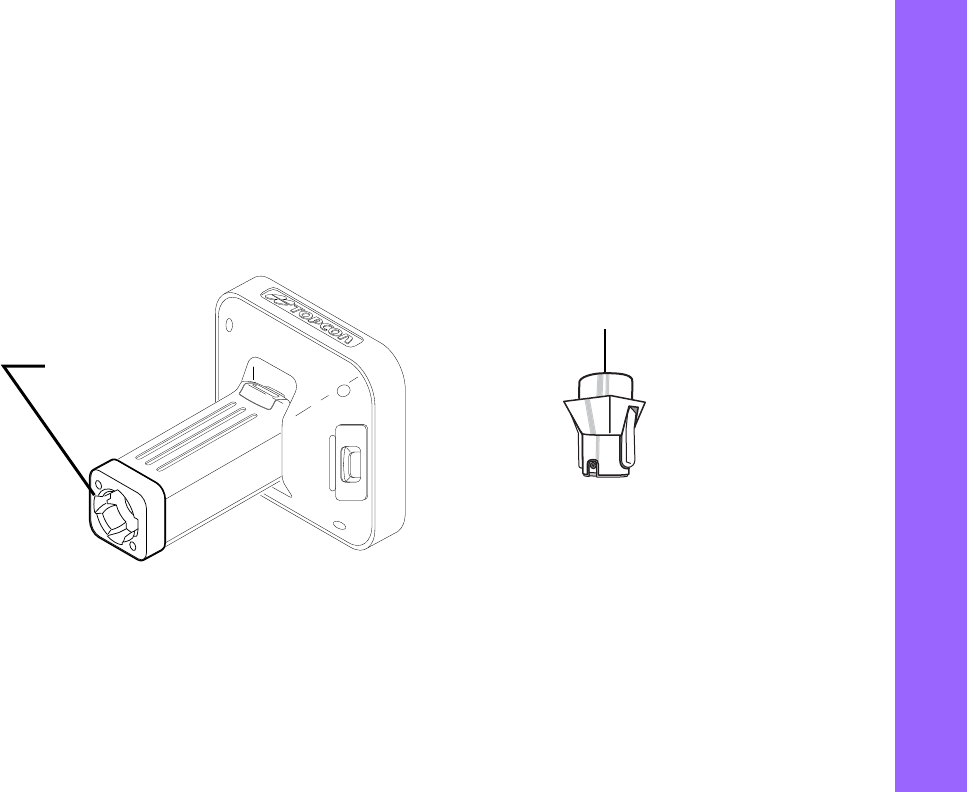
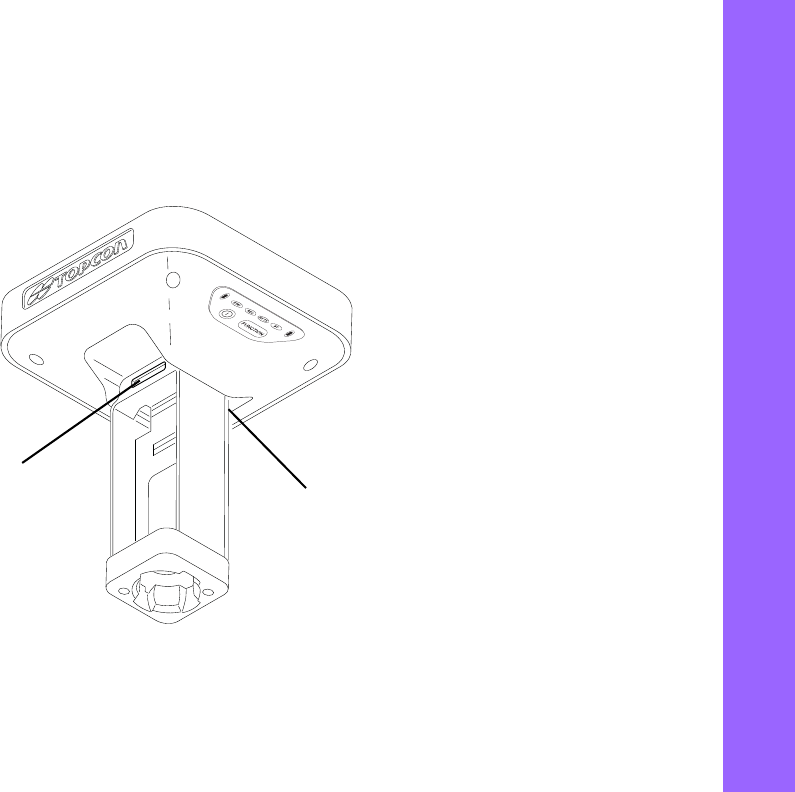
Bottom Connector
The bottom connector (Figure 5) connects the receiver to either a standard 5/8'' thread pole/adapter or the quick
disconnect. The quick disconnect adapter (p/n: 02-850905-01) connects to the range pole for the receiver to
slip into the top. Using the side clips, the receiver can be quickly connected to/disconnected from the range
pole.
Figure5:GR‐5QuickConnector
Bottom Connector
for Standard Setups
Quick Disconnect
Adapter
Getting Acquainted
SD/SDHCandSIMCardSlots
17
P/N:7010‐1004
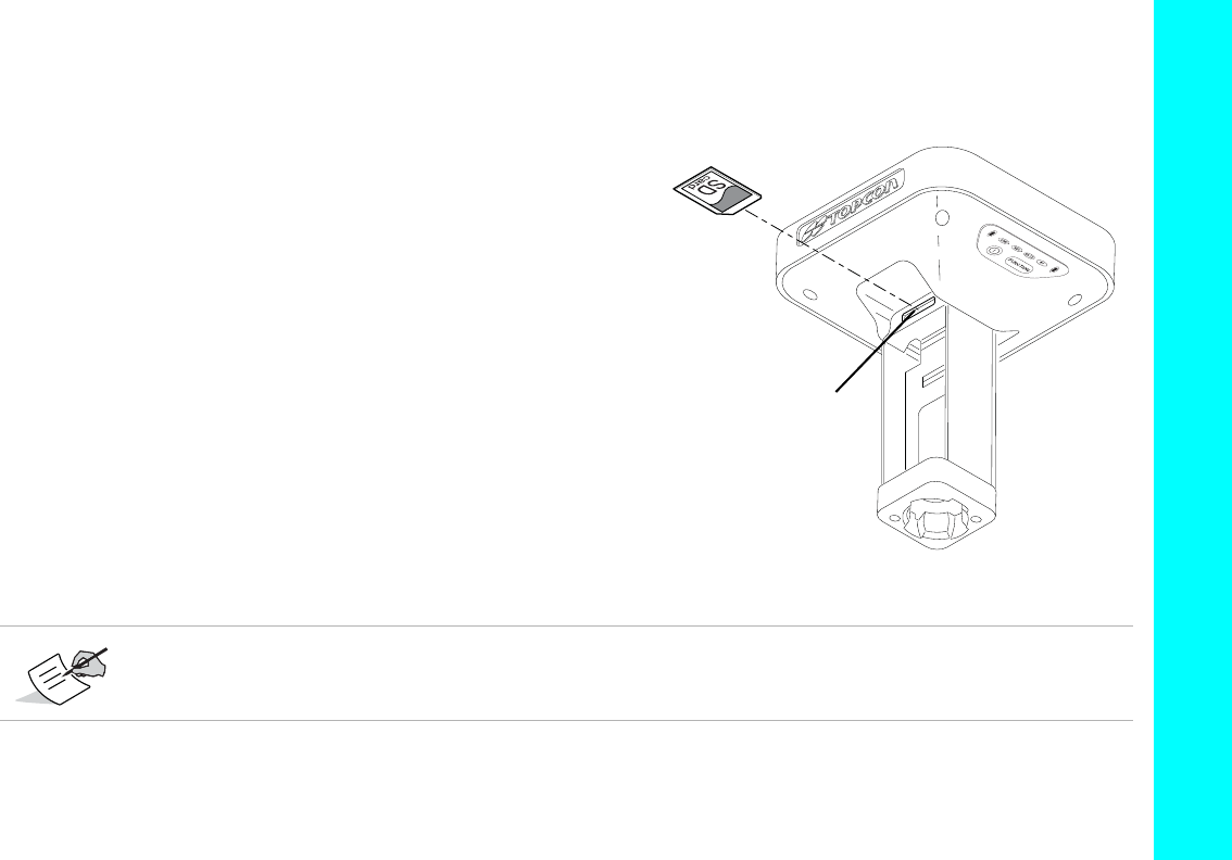
SD/SDHC and SIM Card Slots
TheSD/SDHCandSIMcardslotsarelocatedunderthebatterycompartmentsnearthebaseofthedome.Formore
informationabouttheSD/SDHCcard,see“Memory”onpage59.FormoreinformationaboutSIMcards,see“SIMCard
Slot”onpage18.
Figure6:GR‐5CardSlots
MemoryCard
SlotisHere SIMCardSlot
isHere

Getting Acquainted
SD/SDHCandSIMCardSlots
18
P/N:7010‐1004
SIM Card Slot
TheSIMcardslotislocatedtotherightoftheLEDDisplayPanelinsidethebatterycompartment.Itenablesyoutoinstall
astandardSIMcardintothereceiver.Onceinstalled,theSIMcardprovidesauniqueidentificationforthereceiver’sHSPA
moduleandenablesthereceiver’sHSPAfunctionalitybasedonthesubscribedservices(thereceiverboardaccessesthe
HSPAmodule,whichaccessestheSIMcard).TheSIMcardusuallyremainsinsidethereceiver.YoucanaccesstheHSPA
module,withtheSIMcardinstalled,viaTRUforconfigurationpurposes.ASIMcardcanbepurchasedfromalocalcellular
provider.
SIM Cards
TheSIMcardmusthaveGPRSsupporttocommunicateoveraTCP/IPnetwork.
Installing the SIM Card
1. Makesurethereceiveristurnedoff.
2. RemovethedetachablebatterytotherightoftheLEDDisplaypanel.
3. CarefullyinserttheSIMcard,label‐sideup,intotheSIMcardslotlocatedatthetopofthebatterycompartment.
Oncethereceiveristurnedon,thereceiverboardwilldetecttheSIMcard,anditwillbereadytouseasneeded.
TheGR‐5receiver,equippedwithaCDMAmodule,doesnotrequireaSIMcardandisonlyapprovedtowork
onaVerizon®wirelessnetwork.NotetheMEID#printedontheGR‐5unitorextractedfromTRU,andcall
VerizontoactivateserviceontheCDMAmodule.installedontheGR‐5receiver.
DisplayPanelOperations
19
P/N:7010‐1004
• • • • • •
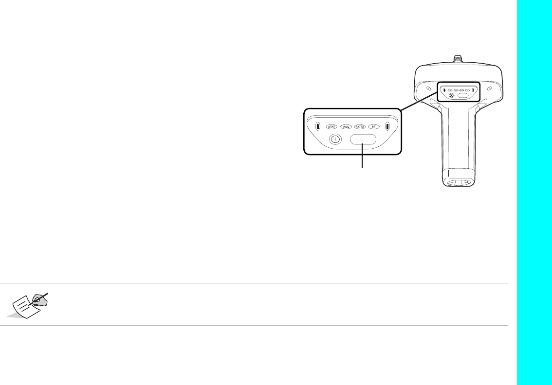
Display Panel Operations
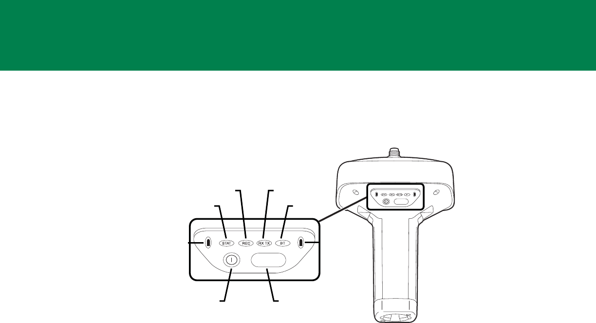
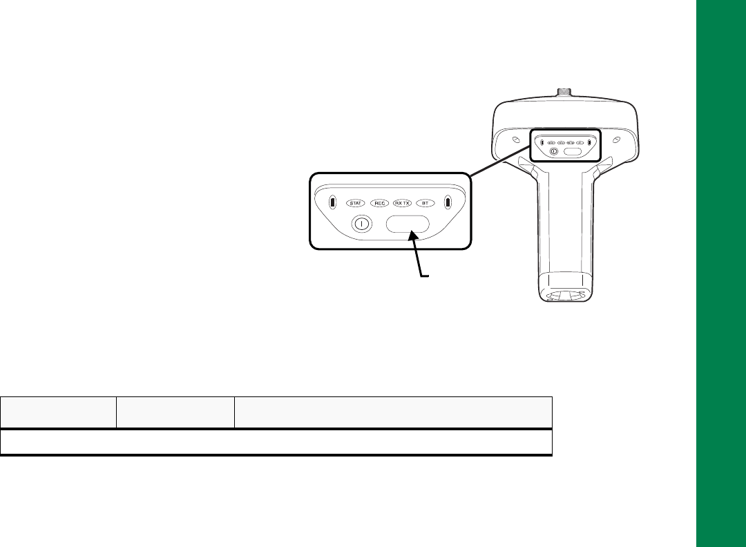
TheLEDdisplaypanel(Figure7)enablesyoutocontrolreceiverpoweranddatarecording.TheLEDsdisplaythestatusof
thesatellitetracking,recording/memorycapacity,Bluetoothconnections,andbatteries.Thischapterdescribesthedifferent
LEDblinkpatternsandwhattheymean.
Figure7:LEDDisplayPanel
FUNCTION
FUNCTION
Battery
STAT
REC RX TX
BT
Power
Button
FUNCTION
Button
Battery
Display Panel Operations
PowerButton
20
P/N:7010‐1004
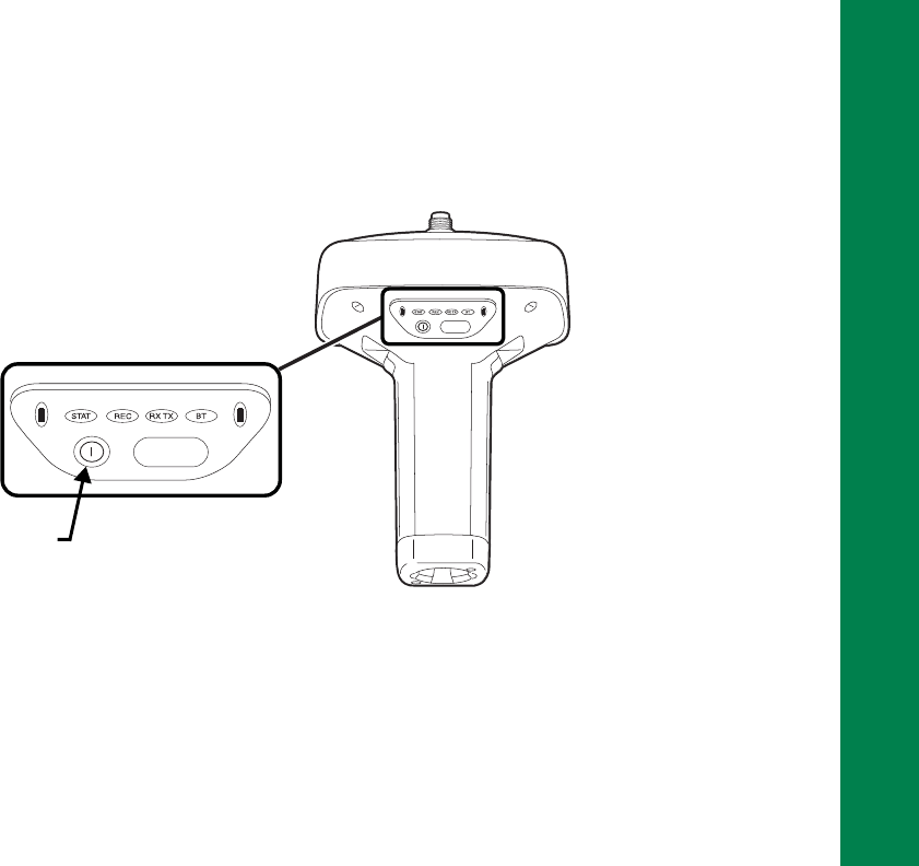
Power Button
Thepowerbuttonturnsthereceiveronandoff.Whenturningthereceiveron,pressthePowerbuttonuntiltheLEDs
brieflyflash.Whenturningoffthereceiver,pressthePowerbuttonuntiltheLEDsgoout.
Figure8:PowerButtonFunctions
Receiver Status LEDs
TherearefourstatusLEDstoprovideyouinformationaboutthebatterylife,trackedsatellites,memorycapacity,and
Bluetoothwirelessconnectivity.ThissectiondescribesthecolorandbehaviorofeachLED.
FUNCTION
FUNCTION
Power
Button
Press the power
button for about 1
second to turn the
receiver on/off.
Display Panel Operations
ReceiverStatusLEDs
21
P/N:7010‐1004
STAT LED
ThetrackingstatusLEDdisplaysthestatusoftrackedsatelliteswhenthereceiverison.
REC LED
TherecordingLEDindicatesifdataisbeingwrittentomemoryandwarnsifmemoryisavailableforrecording.Fora
descriptionoftheRECLEDstatuswhenusingtheFUNCTIONbutton,seeTable7.
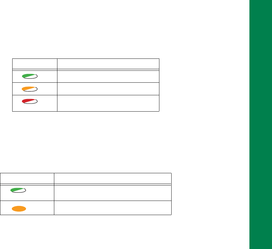
Table2.StatusLEDPatterns
LED Color Description
OneblinkpertrackedGPSsatellite.
OneblinkpertrackedGLONASSsatellite.
Oneblinkmeansnosatelliteisbeing
tracked.
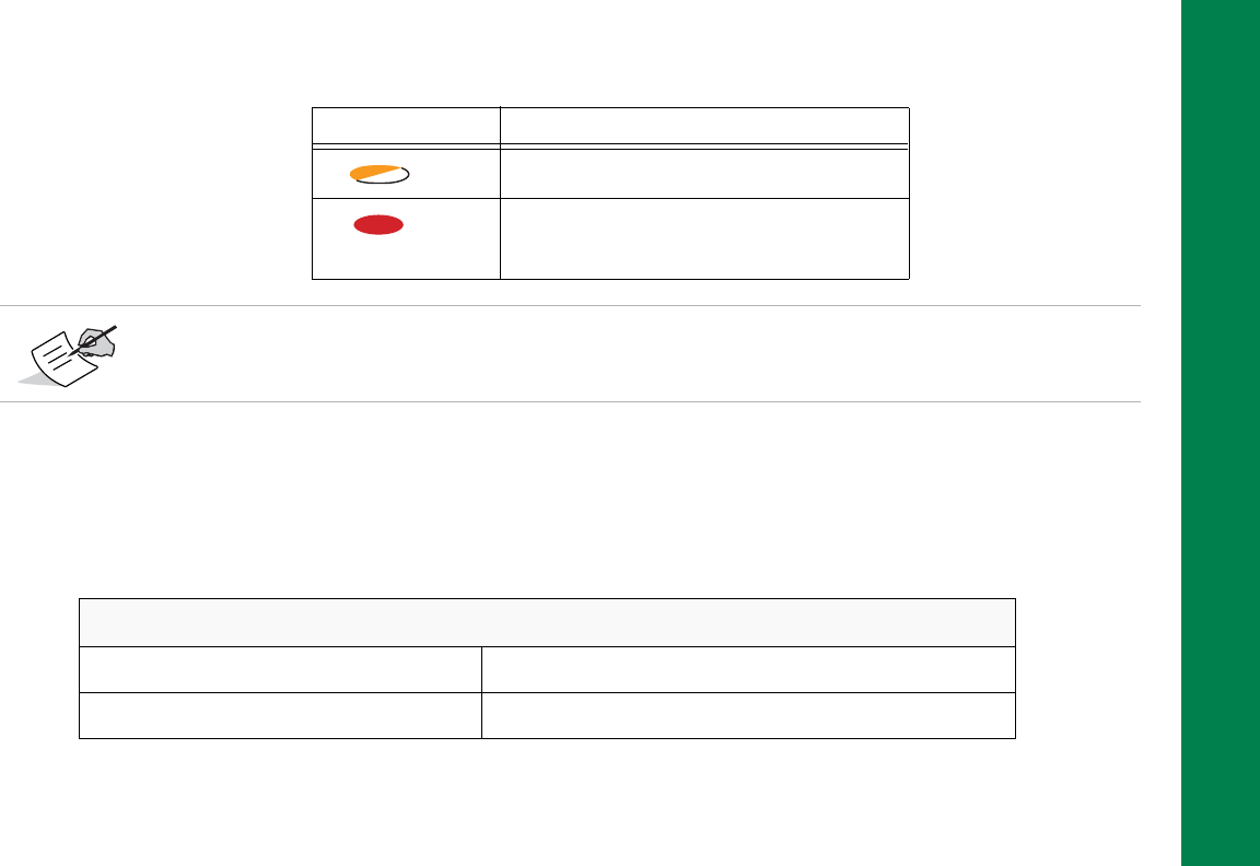
Table3.RecordingLEDPatterns
Display Description
GreenBlink:Fileloggingisinprogress.Eachblink
indicatesdataisbeingwrittentotheSDHCcard.
SolidOrange:Thereceiverischangingmodes.
Display Panel Operations
ReceiverStatusLEDs
22
P/N:7010‐1004
RX TX LED
ThisLEDdisplaysthestatusofthemodem.Table4describestheLEDcolorsandpatternsforthedifferentmodems
availablefortheGR‐5receiver.
OrangeBlink:Thefilesystemisnotaccessible.
SolidRed:Afaultconditionwiththereceiver(no
morememory,noSDHCcardinserted,a
hardwareproblem,oranimproperOAF.
Table3.RecordingLEDPatterns
Display Description
FormoreinformationonRECLEDpatterns,see“FUNCTIONButton/LoggingData”onpage26.
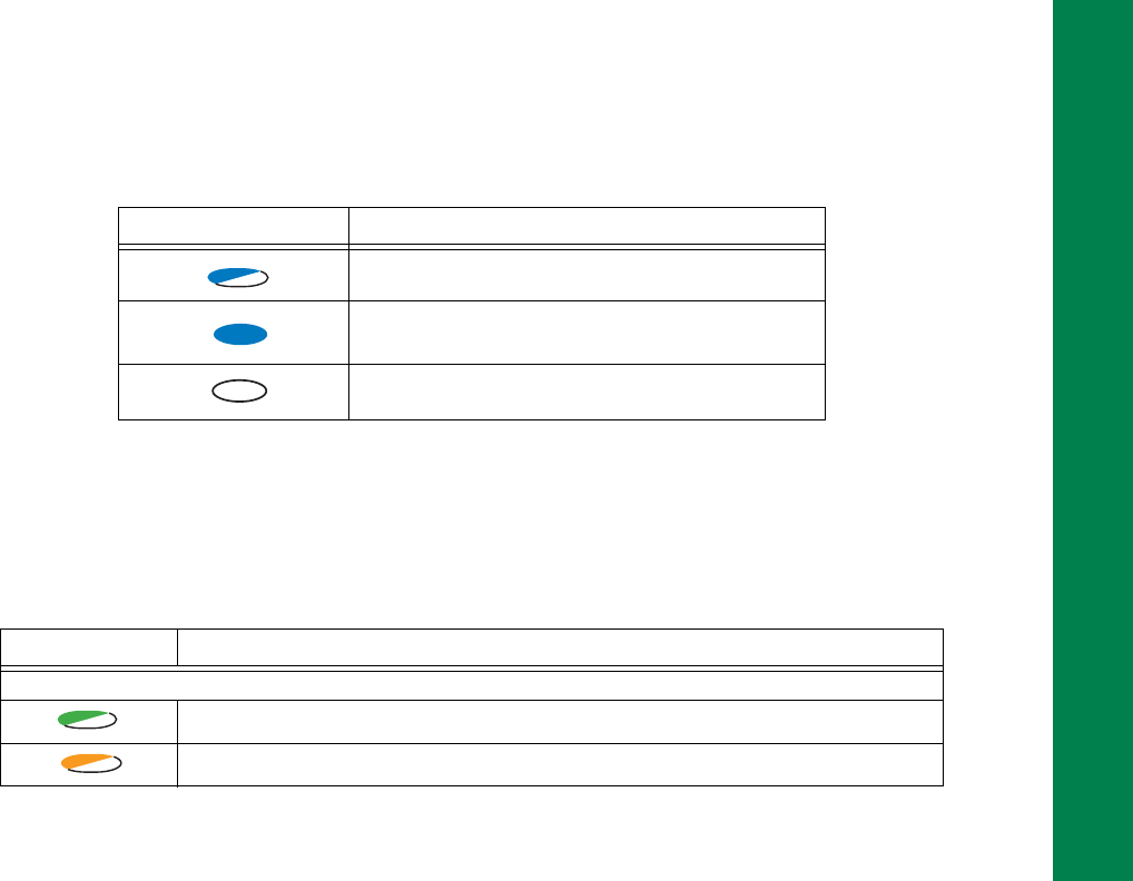
Table4.GR‐5LEDs
FH915/Digital II
NoLight ModemisturnedOff
GreenFlashes(greenLED,off,greenLED) Modemisinreceivermode

Display Panel Operations
ReceiverStatusLEDs
23
P/N:7010‐1004
SolidGreen Aradiolinkhasbeenestablished;modemisreadytoreceive
data
SolidGreenplusyellow(greenLED,greenLED+
redLED) Modemisreceivingdata(Yellowduringactualreception)
SolidRed Modemisintransmittermode
RedFlashes(rapidredLED,off,redLED) Afaultconditionhasbeendetected
RedthenGreen(RedLED,off,greenLED,off) Modemisincommandmode
GSM/HSPA
SolidYellow(RedLED+GreenLED) Modemisinitializing
GreenFlashes Themodemison,registeredonthenetwork,andiswaitingfor
incomingcalls
SolidRed Aconnectionhadbeenestablished
GreenBlinks(DUHFIIorSpSp) Themodemisindirectcontrolmode(DaisyChain)
Yellowflashes(greenLED+redLED,off) anerrorhasoccurred(initializationerror,wrongPINcodeetc.)
Table4.GR‐5LEDs
Display Panel Operations
BatteryLED
24
P/N:7010‐1004
Bluetooth LED
TheBluetoothLEDdisplaysthestatusoftheBluetoothactivity.Table5describestheactivity.
Battery LED
TheBatteryLEDindicatestheremainingchargeofeachdetachablebattery.Whenanexternalpowersourceisutilized,
thePowerbuttonLEDturnssolidgreenandbeginstoblinkifthebatteriesbegintocharge.SeeTable6formore
information.
Table5.BluetoothLEDPatterns
LED Color Description
BlueBlink:Bluetoothisonandwaitingforaconnection.
BlueSolid:AsingleBluetoothconnectionisestablished.
Nolight:Bluetoothisturnedoff.
Table6.BatteryLEDPatterns
LED Color Description
THE RECEIVER IS ON; USING BATTERY POWER
SlowGreenBlink(5sec.):Thechargeisgreaterthan85percent.
SlowOrangeBlink(5sec.):Thechargeisintermediate.

Display Panel Operations
BatteryLED
25
P/N:7010‐1004
SlowRedBlink(5sec.):Thechargeislessthan15percent.
EXTERNAL POWER IN USE(POWER BUTTON LED SOLID GREEN);BATTERIES ATTACHEDa,b
FastGreenBlink(1Sec.):Theinternalbatteriesareatgreaterthan85%capacity;thebatteries
arebeingcharged.
FastOrangeBlink(1Sec.):Theinternalbatteriesareatgreaterthan15%capacity;the
batteriesarebeingcharged.
FastRedBlink(1Sec.):Theinternalbatteriesareatlessthan15%capacity;thebatteriesare
beingcharged.
a.Thereceiverisonoroff.
b.Youcanalsochargethebatteriesusingthebatterychargingcradle.Seepage“BatteryChargingCradle”onpage32.
Table6.BatteryLEDPatterns
LED Color Description
Display Panel Operations
FUNCTIONButton/LoggingData
26
P/N:7010‐1004
FUNCTION Button/Logging Data
Thisbuttonswitchesthereceiverbetween
informationmodesandpost‐processing
modes,starts/stopsdatarecording,and
changesthebaudrateoftheserialportto
9600.TheFUNCTIONbuttonenablesyouto
turndatarecordingonoroff.SeeTable7to
learnhowtousetheFUNCTIONbutton.
Eachtimedatarecordingisturnedofforon,
eitheranewfileopensordataappendstoa
particularfile.
Figure9:FUNCTIONButton
FUNCTION
FUNCTION
Press the FUNCTION
button for 1–5
seconds to start/stop
data logging.
FUNCTION
Button
Table7.FUNCTIONButtonOperationsandRECLEDStatus
FUNCTION Key REC LED Status
Whendatarecordingisoff,andtheFUNCTIONkeyis...

Display Panel Operations
FUNCTIONButton/LoggingData
27
P/N:7010‐1004
Notpressed
Nolight Nodatarecording.
Orangeblink Internalfilesystemtestinprogress.
Red Nofreememory;hardwareproblemwithdatarecording.
NoSDHCcard.
Pressedfor<1
second
IfFUNCTIONkeymodeis“LEDblinkmodeswitch”
Orange Releasetochangeinformationmode.
IfFUNCTIONkeymodeis“Occupationmodeswitch”
Orange Nofunction.
Pressedfor1–5
seconds
IfFUNCTIONkeymodeis“LEDblinkmodeswitch”
Green Releasetostartdatarecording(post‐processingoccupation
modeundefined).
IfFUNCTIONkeymodeis“Occupationmodeswitch”
Green Releasetostartrecording(KinematicorStaticpost‐
processingoccupationmode).
Pressedfor5–8
seconds
Red ReleasetoturnserialportAbaudrateto9600bps.
Table7.FUNCTIONButtonOperationsandRECLEDStatus(Continued)
FUNCTION Key REC LED Status

Display Panel Operations
FUNCTIONButton/LoggingData
28
P/N:7010‐1004
Pressedfor>8
seconds
Nolight Nofunction.
Whendatarecordingison,andtheFUNCTIONkeyis...
Notpressed
Red Nofreememory;hardwareproblemwithdatarecording.
IfFUNCTIONkeymodeis“LEDblinkmodeswitch”
Green Datarecordingstarted(post‐processingoccupationmode
undefined).
IfFUNCTIONkeymodeis“Occupationmodeswitch”
Green Datarecordingstarted(Kinematicpost‐processing
occupationmode).
Orange Datarecordingstarted(Staticpost‐processingoccupation
mode).
Pressedfor<1
second
IfFUNCTIONkeymodeis“LEDblinkmodeswitch”
Orange Releasetochangeinformationmode.
IfFUNCTIONkeymodeis“Occupationmodeswitch”
Orange ReleasetotogglebetweenStaticandKinematicpost‐
processingmodes.
Table7.FUNCTIONButtonOperationsandRECLEDStatus(Continued)
FUNCTION Key REC LED Status

Display Panel Operations
FUNCTIONButton/LoggingData
29
P/N:7010‐1004
Pressedfor1–5
seconds
Nolight Releasetostopdatarecording.
Pressedfor5–8
seconds
Red ReleasetoturnserialportAbaudrateto9600bps.
Pressedfor>8
seconds
Nolight Nofunction(datarecordingstillon).
Table7.FUNCTIONButtonOperationsandRECLEDStatus(Continued)
FUNCTION Key REC LED Status

ManagingPower
30
P/N:7010‐1004
• • • • • •
Managing Power
Thischapterdescribeshowtopowerthereceiver,chargethedetachablebatteries,anduseanexternalpowersource.
Turning On/Off the Receiver
Toturnonthereceiver,pressandholdthepowerbuttonformorethanoneseconduntiltheLEDsbrieflyflash.Whenthe
receiveristurnedon,thereceiver’schannelsinitializeandbegintrackingsatellitesfrommultipleconstellations(depending
onthereceiver’ssupportedfeaturesandcurrentOAF).
Toturnoffthereceiver,pressandholdthepowerbuttonformorethanoneandlessthanfourseconds(untilboththeSTAT
andtheRECLEDsareoff).
Powering the Receiver
Thereceiverispoweredbythedetachable,rechargeablebatteriesoranexternalpowersourceconnectedtothepower
port.Ifanexternalpowersourceisconnected,thereceiverdrawspowerfromitoverthebattery.
Thereceiverwilldrawasmallamountofpowerfromthebatterieswhenitisturnedoff.Ifthereceiveris
placedinstorageforalongperiod,suchasafewmonths,thebatteriesmaybecomefullydischarged.Youwill
needtouseanexternalpowersupplyorrechargethebatteriesbeforeuse.

Managing Power
PoweringtheReceiver
31
P/N:7010‐1004
Detachable External Batteries
Eachdetachablebatteryprovidesbetween5and10hoursofoperation,dependingonthereceivermode.
Tocheckthestatusofthedetachablebatteries,viewtheBATTLEDorcheckthestatususingavailableTopconsoftware.
Charging the Batteries
Thebatteriesareshippedfromthefactorywithoutpower.Fullychargethebatteriesbeforesurveying.Youcanusethe
powersupplyunitorthebatterychargingcradletochargethebatteries.
Power Supply Unit
Thepowersupplyunit(p/n22‐034101‐01)chargestheexternalbatterieswhenconnectedtoagroundedoutlet.Thisunit
convertsthealternatingcurrent(AC)normallysuppliedfromanelectricaloutlettoadirectcurrent(DC)usedtocharge
thebatteriesand/orpowerthereceiver.
Youcanconnectthepowersupplyunittothechargingcradleordirectlytothereceiver.See“PowerSupplyUnit”on
page32.Thepowersupplyhasthefollowingspecifications:
•
inputvoltage–between100and240VAC
•
frequencyofinputpower–between50Hzand60Hz
•
outputvoltage–12VDC@2.5A(30W)
Thepowersupplyunitisdesignedforindooruseonly.Donotuseinadamporawetenvironment.
Donotexposethepowersupplytorainorsnow.Itshouldonlybeusedforchargingthebatteries.
Donotuseasapowersourceduringsurveying.

Managing Power
PoweringtheReceiver
32
P/N:7010‐1004
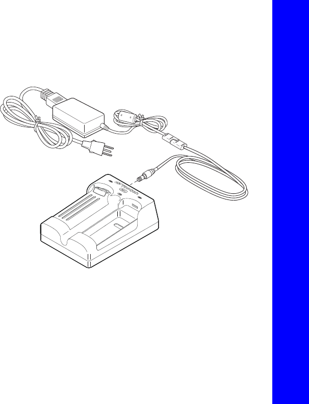
Figure10:PowerSupplyUnit
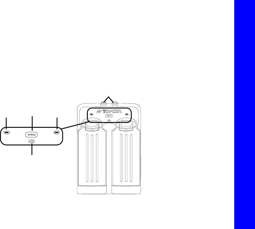
Battery Charging Cradle
Thebatterychargingcradle(Figure11)connectstoastandardpoweroutletusingthepoweradaptercableandpower
cable/powersupplyunit.
Thechargerhastwoports,onebutton,andthreeLEDs.
•
Thetwoportsconnectthechargertoeitherareceiveroranexternalpowersource.Theportschargeordrainthe
batteriessimultaneously.
To grounded outlet
ToReceiver
ToGroundedOutlet
Managing Power
PoweringtheReceiver
33
P/N:7010‐1004
•
TheSTATUSbuttonactivatesthebatteryLEDs.
Press
STATUS
todisplaytheamountofchargeforthecorrespondingbattery.
•
ThetwobatteryLEDsdisplaythepercentageofchargeintheattachedbattery:
–Agreenlightindicatesachargegreaterthan85%.
–Anorangelightindicatesanintermediatecharge.
–Aredlightindicatesachargeoflessthan15%.Rechargeorreplacethebatteryassoonaspossible.
•
ThepowerLEDlightsupwhenthechargerisconnectedtoanexternalpowersource;suchasanelectricaloutletor
anotherpowersource(12voltbattery).
Figure11:BatteryChargerCradlewithBatteries
Battery
STATUS
Button Battery
Power
Two power in/out ports

Managing Power
PoweringtheReceiver
34
P/N:7010‐1004
Youcanalsoattachthebatterychargertoatripod,abelt,oranRTKpoletoprovideexternalpowertothebasestationor
rover.
BeforeusingtheGR‐5,fullychargethebatteriesformaximumoperatingtime.
Battery Charging Temperatures
Chargethebatteriesonlyintemperaturesbetween32oF(0oC)and113oF(45oC).
Anoptimalchargingtemperatureisbetween50oF(10oC)and77oF(25oC).Ifpossible,chargethe
batterieswithinthistemperaturerange.
Charging Procedure
Therearetwowaystochargethereceiver’sdetachablebatteries:
•
whiletheyareattachedtothereceiver
•
whiletheyareattachedtothechargingcradle
Ifthebatteriesareattachedtothereceiverortothechargingcradle,inapproximatelysixhoursthebatterieswillbe
simultaneouslyfullycharged.
TheLi‐Ionbatteriesusedinthebatterypacksshouldrunatnolessthan80%capacityafter500chargingcycles.Youdo
notneedtodrainthesebatteriesbeforerecharging.
0oC
32oF
45oC
113oF
10oC
50oF
25oC
77oF
Managing Power
PoweringtheReceiver
35
P/N:7010‐1004
Tochargethebatteriesusingthepowersupplyunit:
1. Plugthereceiver‐to‐SAEpowercableintothe
receiver’spowerinputport.
2. Connectthereceiver‐to‐SAEpowercableandthe
powersupply‐to‐outletcabletotheACadapter.
3. Plugthepowersupply‐to‐outletcableintoan
availableoutlet.Thebatteriesarefullycharged
afterapproximately6hours.
Tochargethebatteriesusingthechargingcradle:
1. Removethebatteriesfromthereceiverandinsert
themintothechargingcradle.
2. Connectthepowercabletothepowersupplyunit.
3. ConnecttheSAEconnectorsonthepoweradapter
cableandpowersupplyunit.
4. Connectthepoweradaptercabletooneofthe
portsonthechargingcradle(eitherportwillcharge
both/eitherbattery).
5. Plugthepowersupplytoanavailableoutlet.The
batteriesarefullychargedafterapproximately6
hours.
Figure12:ChargingBatteries
To grounded outlet
Managing Power
PoweringtheReceiver
36
P/N:7010‐1004
Leaving the Batteries on Charge
Thebatteriescanbesafelyleftinthereceiverorthechargingcradleoncechargingiscomplete.Doingsowillnot
overchargeordamagethebatteries.
Thebatteriescanalsobeattached/detachedto/fromthereceiverorchargingcradleatanytimewithoutharmingthe
batteries,thereceiver,orthecradle.Whenreturningthebatteriestothereceiverorcradle,chargingisautomatically
resumed.
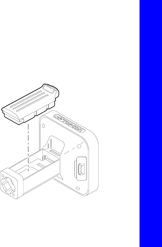
Attaching the Batteries
ToattachthebatteriestotheGR‐5(Figure13):
1. Withthebatteryslightlytipped,placethebottom
ofthebatteryintothebottomofthebattery
compartment.
2. Gentlypushthetopofthebatteryintothebattery
compartmentuntilitsnapsintoplace.Makesure
thattheclipatthetopofthebatterycompletely
snapsintoplace.
Figure13:InsertingtheGR‐5Batteries
Managing Power
PoweringtheReceiver
37
P/N:7010‐1004
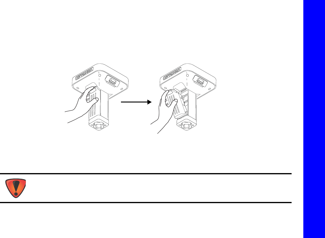
Detaching the Batteries
TodetachthebatteriesfromtheGR‐5,sothattheycanbechargedorreplaced:
Usingtheclipatthetopofthebattery,gentlypulldownandouttodetachthebatteryfromthereceiver(Figure14).
Figure14:DetachtheGR‐5Batteries
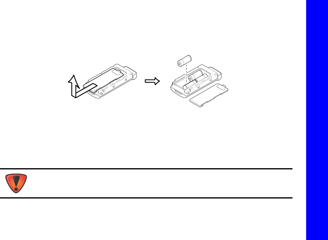
Assembling the AA Battery Shell
ToassembletheAAbatteryshelltotheGR‐5(Figure15):
1. SlidethebackcoveroftheAAbatteryshelldownandliftoff.
DonotuserechargeableAAbatteries.
DonotusetheAAbatteryshellwhentheradiomodemisintransmittermode.
Managing Power
PoweringtheReceiver
38
P/N:7010‐1004
2. InsertfourAAbatteriesasshownontheinsideoftheshell(andinFigure15below).
•
Thebatteriesontheleftlaywiththepositiveendtowardsthebottomoftheshell.
•
Thebatteriesontherightlaywiththepositiveendtowardsthetopoftheshell.
3. Replacethebackcoveroftheshell.
Figure15:RemoveCoverandInsertAABatteries
4. InserttheAAbatteryshellintothebatterycompartmentofthereceiverasshowninFigure13onpage4‐36.
Surveying While Charging
TheusercanexecuteanykindofsurveyingwhilechargingtheinternalbatteriesattachedtotheGR‐5withoutdegradation
ofperformance.
- + - +
+ -
+ -
Whilecharging,makesuretheairtemperatureisbetween+32oF(0oC)and+113oF(+45oC).Thisis
importanttopreventseriousdamagetothebatteries,thereceiverorinjurytopersons.

Managing Power
PoweringtheReceiver
39
P/N:7010‐1004
Changing the Batteries while Surveying
Itissafetochangeadepletedbatterywithafullychargedonewhilesurveying(i.e.,onthefly)withoutturningoffthe
receiver.Beforedoingthis,makesuretheotherbatteryhasenoughchargetopowerthereceiverwhilechangingthe
depletedbattery.Thesurveyingwillnotbedisrupted.Ifneeded,repeatthisprocedureforthesecondbattery.
Using an Auxiliary Power Source
Inadditiontothedetachablebatteries,youcanconnectthereceivertoanexternalpowersource,suchasavehiclebattery
with9to21VDC,tooperatethereceiverandforcontinuoususeofthereceiverifthedetachablebatteriesbecome
discharged.
Toconnectthereceivertoanauxiliarybattery(Figure16onpage4‐40):
UsetheODU‐to‐alligatorclipscable(p/n14‐008097‐01LF)todirectlyconnecttheauxiliarybatteryandthereceiver’s
powerport(withoutSAE).
1. ConnecttheODU‐to‐alligatorclipscabletoa12‐voltbattery.
2. ConnecttheODU‐to‐alligatorclipscabletothereceiver’spowerport.
Powerinputgreaterthan21VDCcoulddamagethereceiver.
Whenpoweringthereceiverusingexternalbatteries,setthechargermodetoOff;otherwise,the
detachablebatterieswillalsocharge,causingoperationtimetodecrease.
Managing Power
PoweringtheReceiver
40
P/N:7010‐1004
3. Turnonthereceiver.
Figure16:ConnectanAuxiliaryBatteryandtheReceiver
Asingleexternal12V,2.3A*hbatteryshouldrunthereceiverandmodemforabout9hoursandthereceiverfor13hours.
FromReceivertoAuxiliaryBattery
UsingODU‐to‐AlligatorClipsCable
Managing Power
PoweringtheReceiver
41
P/N:7010‐1004
Toconnectthereceivertothechargingcradle(Figure17):
Thechargingcradlewithextrabatterieshooksontoatripodorbeltforaconvenientpowersupplyforthereceiver.The
partnumberforthereceiver‐to‐chargercradlecableis14‐008072‐01or14‐008072‐02.
1. Connectoneendofthecradle‐to‐receivercabletothechargingcradle.
2. Connecttheotherendtothepowerportonthereceiver.
Figure17:ConnecttheChargingCradleandReceiver
TheBatteriesintheChargingCradledo
notChargetheInternal/Detachable
Batteries.TheChargingCradlePowers
theReceiver

Managing Power
InsufficientPower
42
P/N:7010‐1004
Insufficient Power
Ifthebatteriesbecomefullydischargedandanexternalpowersupplyisnotconnected,thereceiverwillshutdownand
automaticallysaverecordedfiles.Toavoiddisruptions,checktheBATLEDonthedisplaypanelforthebatterycharge
status.See“BatteryLED”onpage24formoreinformation.
Ifthereceivershutsdownduetoinsufficientpower,thereceiverandallcommunicationportsbecomede‐activated.
Torestorepowertoyourreceiverandturnitbackon,dooneorallofthefollowing:
•
Rechargethebatteries.
•
Makesurethepowercableiscorrectlyconnectedtothereceiver’sport.
a. Alignthekeywayswhenconnectingthepower/serialcabletothereceiverport.
b. Turnthecablelockclockwiseuntilitclickstosecurethecableinplace.
c. Todisconnectthecable,turnthelockcounter‐clockwise,andthengentlyremovethecable.
•
Connectthereceivertoadifferentpowersource.
PowersuppliedtothereceivershouldmatchthespecificationsprovidedbyTopconontheproduct.Failureto
complywiththesespecificationsmaydamagethereceiver.See“Specifications”onpage75.

ConfiguringtheReceiver
43
P/N:7010‐1004
• • • • • •
Configuring the Receiver
Thesectionsinthischapterdescribereceiveroptions,andhowtoloadanewOptionAuthorizationFile(OAF),updatefirmware,
andperformafactoryreset.Todothis,youwillneedtousetheTopconReceiverUtility(TRU)softwarethatwassuppliedonthe
GR‐5CD.Forinformationaboutinstallingthesoftware,seetheTopconReceiverUtility(TRU)OnlineHelpembeddedinthe
software.
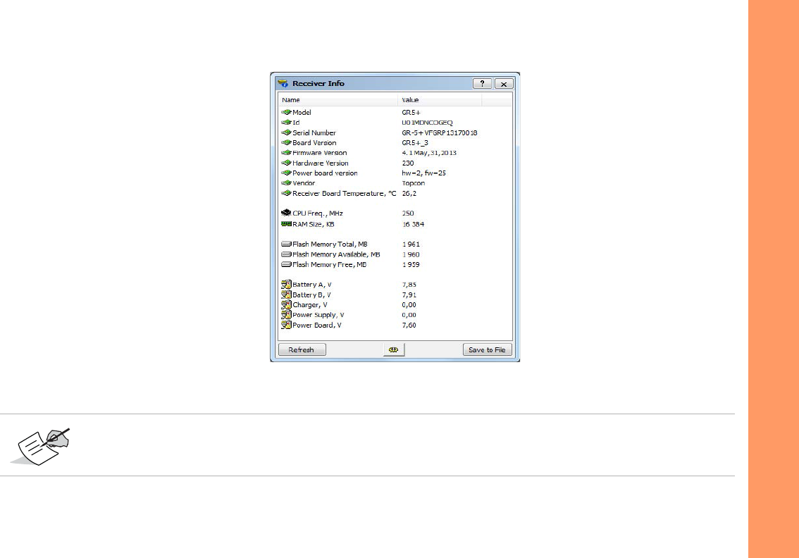
Viewing Receiver Information
IntheTopconReceiverUtility(TRU),the
ReceiverInfo
windowdisplaysbasicreceiverinformation,suchashardwareandfirmware
versions,RAMsize,receiverID,serialnumber,etc.
ToopentheReceiverInfowindow:
1. ConnectthereceivertoacomputerandopenTRU.
2. InTRU,connecttothereceiver.
3. ClickDeviceApplicationModeReceiverManaging.
4. ClickDeviceConnect.
5. IntheConnectionParameterswindow,selectthecorrectserialport,andclickConnect.
6. IntheTRUmainwindow,clicktheInformationicon.TheReceiverInfowindow(Figure18)appears.
Configuring the Receiver
ViewingReceiverInformation
44
P/N:7010‐1004
Figure18:TRU–ReceiverInfo
TheGR‐5receiver,featuringVanguardtechnology,isreferredtoastheGR‐5+todifferentiatefromtheGR‐5
receiverwithanolderreceiverboard.

Configuring the Receiver
LoadingNewFirmware
45
P/N:7010‐1004
Loading New Firmware
Receiverboardfirmwareisreleasedasacompressedfilethatyoudownloadanddecompress.Thisfilecontainsthefollowing
twofiles:
•
ramimage.ldr–theReceiverboardRAMfile
•
main.ldp–theReceiverboardFlashfile
Touploadfirmwarefilestothereceiver:
1. ConnectthereceivertoacomputerusingthePowerandSerialcablereceiveraccessory(p/n:100182‐01).
2. ToconnecttothereceiverinTRU:
a. ClickDeviceApplicationModeFirmwareLoader.
b. ClickDeviceConnect.
c. IntheConnectionParameterswindow(Figure19),selectSerialPortandtheportname,andthenclick
Connect.
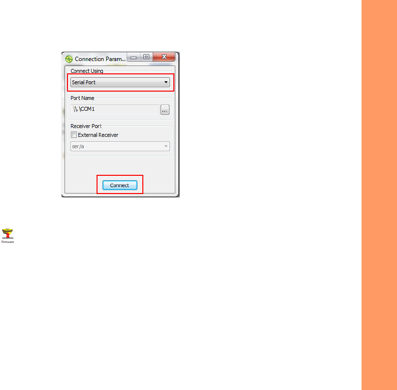
Configuring the Receiver
LoadingNewFirmware
46
P/N:7010‐1004
Figure19:ConnectionParametersWindow
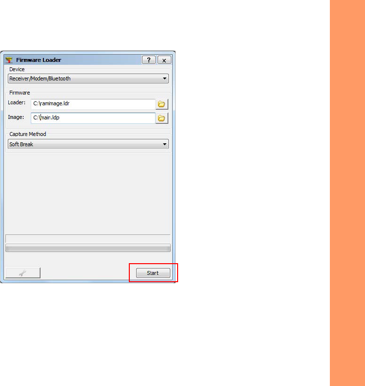
3. ClicktheFirmwareLoader iconintheTRUmainwindow.TheFirmwareLoaderwindow(Figure20)displays.
Thiswindowenablesyoutouploadfirmwarefilestotheconnectedreceiver.
4. MakesureReceiver/Modem/BluetoothisselectedintheDevicefield.
5. (Recommended)SelectSoftBreakastheCaptureMethod.
6. Browseforandselectthereceiverboard’sRAMandFlashfiles(Figure20).
Configuring the Receiver
LoadingNewFirmware
48
P/N:7010‐1004
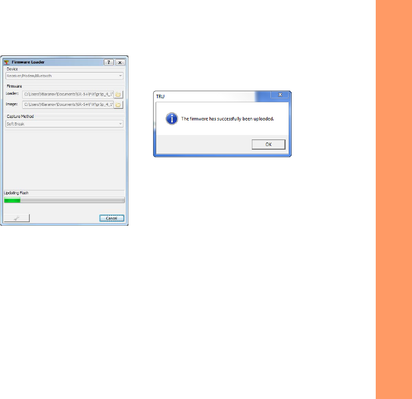
Figure21:FinishingFirmwareUpload

Configuring the Receiver
AbouttheOAF
49
P/N:7010‐1004
About the OAF
TopconissuesanOptionAuthorizationFile(OAF)toenablethespecificoptionsthatyoupurchased.Topcon’sOAFsystemallows
youtocustomizeandconfigurethereceiveraccordingtoyourparticularneeds,thereforepurchasingonlytheoptionsyou
require.
TheGR‐5receivertypicallyshipswithanOAFasperinitialpurchaseofthereceiverkitconfiguration.Thereareseveralupgrade
optionsavailablewiththereceiverthatcanextendthereceiver’sfunctionalitytobettersuityourjobrequirement.Examplesof
upgradeoptionsarelistedbelow:
•
GLONASSL1,L2signaltracking
•
GPSL5signaltracking
•
RTKandupdaterate20,and50Hz(10Hzstandard)
ContactyourTopcondealerorarepresentativeforacompletelistingofavailableoptionsandpricinginformation.
Checking the Receiver’s OAF
TouseTRUtoviewthestatusofthereceiver’soptions:
1. ConnectthereceivertoacomputerandopenTRU.SeetheTopconReceiverUtility(TRU)OnlineHelpformore
informationaboutconnectingthereceivertoacomputer.
2. InTRU,connecttothereceiver.
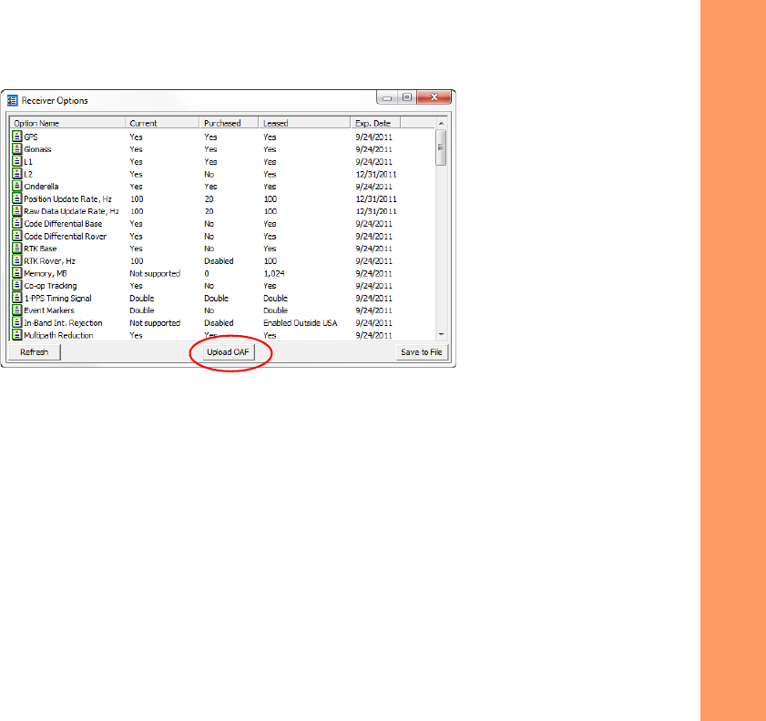
3. ClicktheOptionsiconinthemainwindow.TheReceiverOptionswindow(Figure22)displays,soyoucanview
thecurrentauthorizationoptionsanduploadnewones.
Configuring the Receiver
AbouttheOAF
50
P/N:7010‐1004
Figure22:ReceiverOptions
Loading an OAF
TopcondealersprovidecustomerswithOAFfiles.ForanyOAFrelatedquestions,e‐mailTopconat
options@topcon.com
and
includethereceiver’sIDandserialnumber.Toobtainthesenumbers,see“ViewingReceiverInformation”onpage43.
ToloadanewOAF:
1. Followthestepsin“CheckingtheReceiver’sOAF”onpage49.
2. ClickUploadOAFonthebottomoftheReceiverOptionswindow(seeFigure22).
Configuring the Receiver
AbouttheOAF
51
P/N:7010‐1004
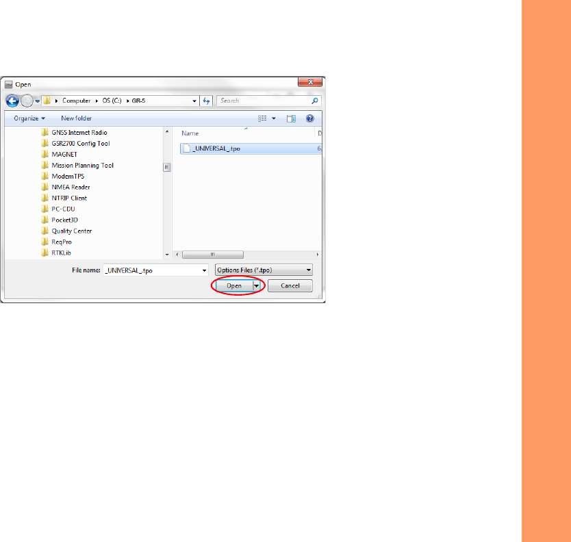
3. NavigatetothelocationofthenewOptionAuthorizationFile(Figure23).
Figure23:LoadOAF
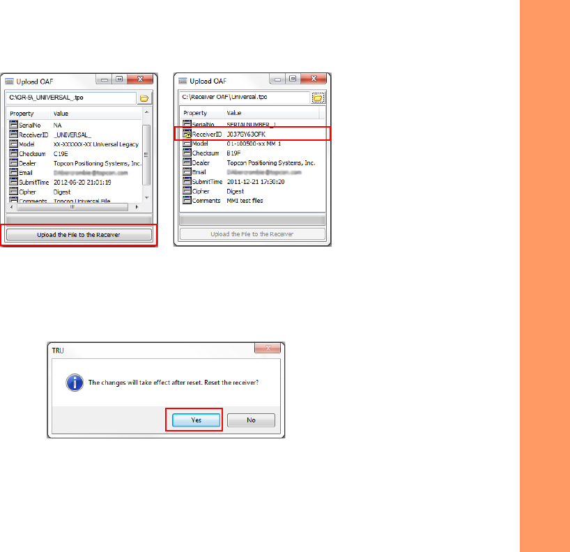
4. Selecttheappropriatefile,andclickOpen(Figure23).
Topcon’sTRUinitiallycheckstoseeiftheselectedfileiscompatiblewiththecurrentlyconnectedreceiver.Ifyou
choseafilenotintendedforthisreceiver,theUploadOAFwindowdisplaysanerroriconnexttotheReceiverIDand
disablestheUploadtheFiletotheReceiverbutton.
Configuring the Receiver
AbouttheOAF
52
P/N:7010‐1004
Figure24:OAFCompatibilityCheck
5. PressUploadtheFiletotheReceiver(Figure24)tostartloadingthefile.
IfanOAFfileisuploadedtothereceiver,TRUwilloffertoresetthereceivertoputnewauthorizationoptionsinto
operation(Figure25).
Figure25:ResettheReceiver
6. ClickYes.

Configuring the Receiver
PerformingaFactoryReset
53
P/N:7010‐1004
Performing a Factory Reset
Thereceiver’sNon‐VolatileRandomAccessMemory(NVRAM)holdsdatarequiredforsatellitetracking,suchasephemerisdata
andreceiverposition.TheNVRAMalsokeepsthecurrentreceiver’ssettings,suchasactiveantennainput,elevationmasksand
recordinginterval,andinformationaboutthereceiver’sinternalfilesystem.Afactoryresetclearsthereceiver’sNVRAMand
restoresthereceiver’sfactorydefaultsettings.
AlthoughafactoryresetorclearingtheNVRAMisnotrecommendedasacommonpractice,therearetimeswhenitcan
eliminatecommunicationortrackingproblems.
Afterafactoryreset,thereceiverrequirestimetocollectnewephemeridesandalmanacs(around15minutes).
Afactoryresetwillnotdeleteanyfilesalreadyrecordedinthereceiver’smemory,andtheNVRAMkeepsinformationaboutthe
receiverfilesystem.
Therearetwowaysyoucanperformafactoryreset:usingTRUandusingtheLEDdisplaypanel.
UsingTRUtocleartheNVRAM:
1. Connectthereceivertoacomputer,andopenTRU.SeetheTopconReceiverUtility(TRU)OnlineHelpformore
informationaboutconnectingthereceivertoacomputer.
2. InTRU,connecttothereceiver.
Configuring the Receiver
PerformingaFactoryReset
54
P/N:7010‐1004
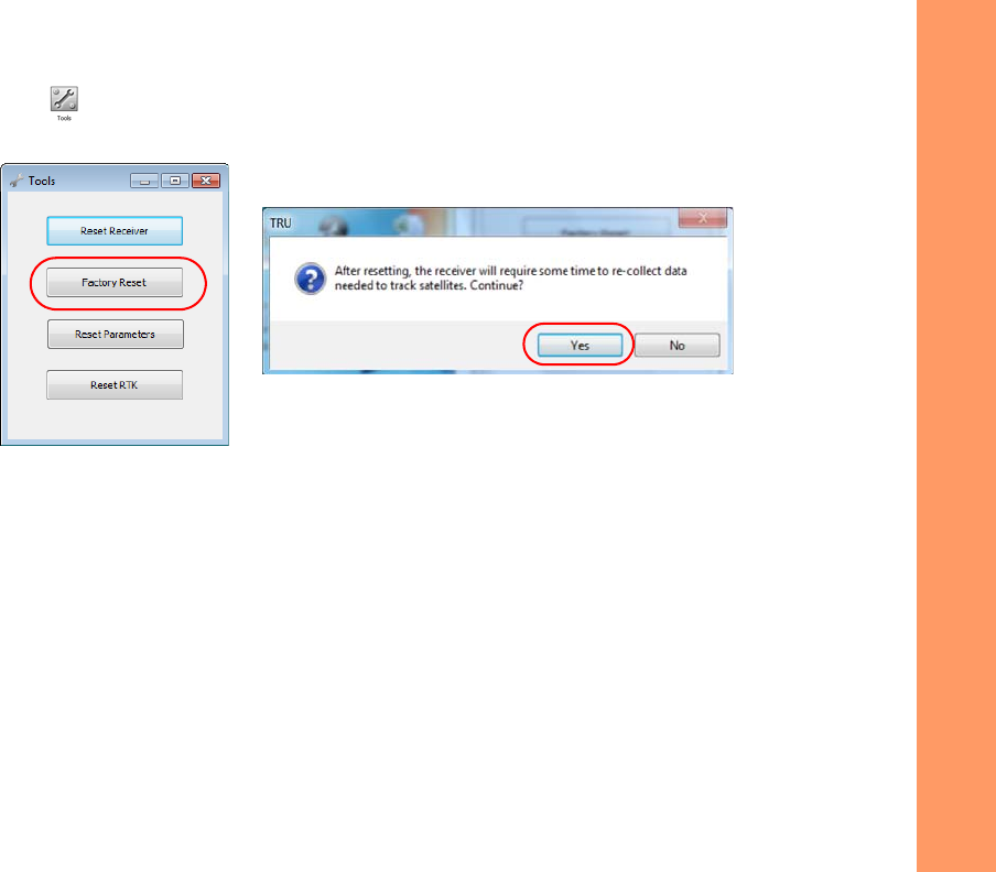
3. ClicktheToolsicon inthemainwindow.
TheToolswindowappears,enablingyoutoresetthereceiverandcleartheNVRAM.
Figure26:ToolsDialogBox
4. ClickFactoryReset,andclickYestocontinue.
UsingtheLEDdisplaypanel
1. PressthePowerbuttontoturnoffthereceiver.
2. PressandholdtheFUNCTIONbutton.
3. PressandholdthePowerbuttonforonesecond,andthenreleaseitwhilecontinuingtoholdtheFUNCTIONbutton.
4. WaituntiltheSTATandRECLEDsturngreen.
5. WaituntiltheSTATandRECLEDsblinkorange.
6. ReleasetheFUNCTIONbuttonwhiletheSTATandRECLEDsblinkorange.

FieldSystemSetup
55
P/N:7010‐1004
• • • • • •
Field System Setup
Thischapterdescribesthefieldsetupofyournewreceiver,soitisreadyforuseasaBase,network,RTKRover,orstaticdata
collector.
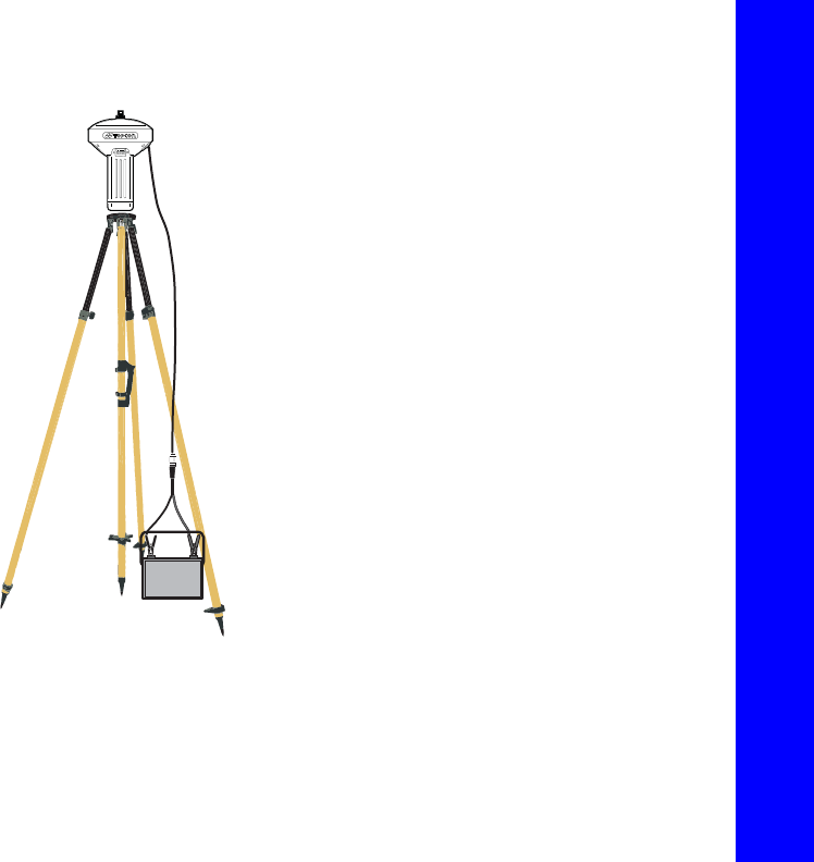
Setting Up the Base Receiver
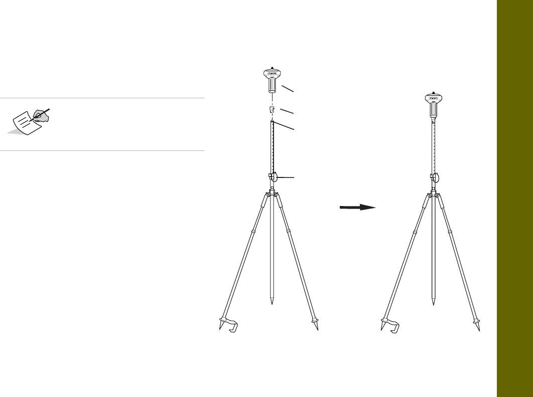
1. Installaheavy‐dutytripod(p/n:22‐050501‐01)
overaknownpoint.Youdonotneedauniversal
tribrachandtribrachadapterwhenworkingwith
thistripod.
2. Attachtheantennatothemodemantenna
connector.
3. Levelthetripodandtightenthescrews.
4. Attachanyotheraccessoriesasneeded,suchasa
back‐uppowersupply.
5. Measuretheheightofthereceiverfromthe
groundusingthetapemeasure.See“Measuring
AntennaHeight”onpage57.
6. ViewtheLEDdisplaypanelforthereceiver’s
currentstatus.Seealso“DisplayPanelOperations”
onpage19.
GR-5 Receiver
Heavy Duty Tripod
Field System Setup
SettingUptheRoverReceiver
56
P/N:7010‐1004
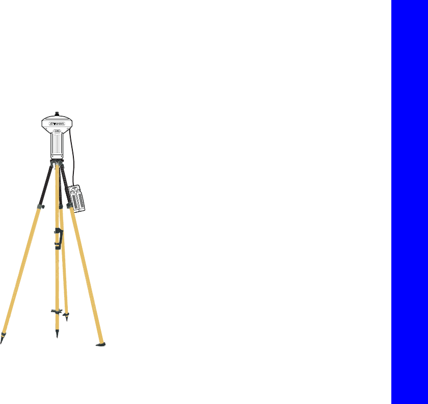
Setting Up the Rover Receiver
1. Ifneeded,attachthequickdisconnecttothe
bipod/rangepole.
2. Attachthereceivertothequickdisconnect.
Makesurethereceiverlocksintoplace.
3. Ifyouarenotusingafixedheightroverpole,
measuretheheightofthereceiverfromthe
ground.See“MeasuringAntennaHeight”on
page57.
4. Attachtheantennatotheantennaconnector.
5. Pressthepowerbuttontoturnonthe
receiver.Theintegratedwirelessdeviceinthe
receiverturnsonwhenthereceiveris
powered.
6. ViewtheLEDdisplaypanelforthereceiver’s
currentstatus.Seealso“DisplayPanel
Operations”onpage19.
Useabipodduringpost‐process
surveystoensurethe
antenna/receiverdoesnot
moveduringdatalogging.
Lock
GR-5 Recevier
5/8 inch Screw
Quick Disconnect (Optional)

Field System Setup
MeasuringAntennaHeight
57
P/N:7010‐1004
Measuring Antenna Height
Thereceivercalculatesthecoordinatesoftheantenna’sphasecenter.Todeterminethecoordinatesofthestationmarker,
specifythefollowing:
•
Measuredheightoftheantennaabovethestationmarker
•
Methodofmeasuringtheantennaheight
•
Modeloftheantenna/receiverused
Anynecessaryantennaphasecenteradjustments,basedontheantennamodel,isautomaticallyapplied.Thisadjustment,when
combinedwithaccuratelymeasuredheightandmeasurementmethods,allowsforcorrectlycomputedreferencemarker
coordinates.
Toaccuratelymeasuretheantennaheight:
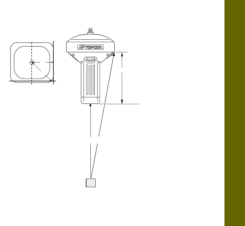
1. Measuretheantennaheightabovethecontrolpointormarker,eithertheslantheightortheverticalheight.
YoumayeithermeasuretheverticalheighttotheAntennaReferencePoint(ARP)locatedatthebottomofthe
receiveratthebaseofthemountingthreads,ormeasuretheslantheighttotheSlantHeightMeasurementMark
(SHMM)onthesideofthereceiver.ForARPandSHMMmarksonthereceiver,seeFigure27.
2. Recordtheantennaheight,pointsname,andstarttimeinthefieldnotes.
Field System Setup
MeasuringAntennaHeight
58
P/N:7010‐1004
Figure27:AntennaHeightMeasurementPoints
168mm
A
B
A = ARP to edge = 79.0
B = ARP to corner = 97.5
LV LS
SHMM
LV = Vertical Length
LS = Slant Length

CollectingData
59
P/N:7010‐1004
• • • • • •
Collecting Data
Thischapterprovidesgeneralinformationaboutmemory,recordingdata,downloadingdata,andremovingfilestofreeupmemory
space.
Memory
TheGR‐5isequippedwithanexternalSD/SDHCmemorycardslot.AlthoughyoumayinstallanSD/SDHCcardofany
memorysizeintotheslot,thereceiverrecognizesupto32GBofmemory.Forspecificinformation,see“SD/SDHCCard
Recommendations”onpage103.ItisnecessarytouserecommendedSD/SDHCcardstoensureaccurateandreliabledata
loggingandminimizeanyoccurrenceofdataloss,cardinitialization,etc.TheOptionalAuthorizationFile(OAF)controlsthe
receiver’smemorycapacity.Asdataisloggedtothecard,theRECLEDdisplaysthememorycapacitystatus.See“RECLED”
onpage21formoreinformation.Toaccesstherawdatafilesonthememorycards,see“ManagingFiles”onpage64.
Collecting Data
Memory
60
P/N:7010‐1004
SD/SDHC Card
TheSDHCcardslotislocatedtotheleftoftheLEDDisplayPanel
insidethebatterycompartmentandconnectsanoptional
SD/SDHCcardtothereceiverboardtoprovidememory.Once
installed,theSD/SDHCcardusuallyremainsinsidethereceiver.
YoucanaccessthedatathatresidesontheSD/SDHCcardviathe
USBorserialport,orBluetoothwirelesstechnology(see
“ManagingFiles”onpage64).Asecuredigitalcardcanbe
purchasedatalocalcomputersupplystore.
Installing the SD/SDHC Card
1. Makesurethereceiveristurnedoff.
2. RemovethedetachablebatterytotheleftoftheLED
Displaypanel.
3. CarefullyinserttheSD/SDHCcard,label‐sidedown,intothe
cardslotlocatedatthetopofthebatterycompartment.
Oncethereceiveristurnedon,thereceiverboardwill
detecttheSD/SDHCcard,anditwillbereadytouseasneeded.
Card Slot
(for SDHC card)
AlwaysinitializethefilesystemontheinstalledSD/SDHCcardbeforethefirstuse.TheInitializationprocedure
isdescribedbelow.

Collecting Data
Memory
61
P/N:7010‐1004
Initializing the File System
TheGR‐5supportsaremovableSDHCmemorycardtolograwdatafiles.Thememorycardmustbeinitializedbeforeits
firstuse.InitializingthememorycardwhileinthereceiverensuresthecardisformattedtotheTPSproprietaryfilesystem
(TPFS).Thisfilesystemallowsthereceivertocreate,store,retrieve,delete,andrestorerawdatafiles.
Itisalsoadvisabletore‐initializethememorycardperiodically(e.g.,quarterly).Thiserasesanydataonthecard,checks
forbadblocks,andsetsthecardupafresh.
TheusercanuseTRUtoinitializethefilesystem.
Initializing the File System Using TRU
1. ConnectthereceivertoacomputerandrunTRU.
2. ClicktheFileExplorericontoopentheFileExplorerscreen.
3. OntheFilestab,pressandholdtherightmousebuttononthefileline.
4. ClickInitializeFileSystem.
Initializingthefilesystemofaconnectedreceiverwilleraseallofthereceiver’sdatafiles.Awarningmessage
willappeartoconfirmtheoperation.

Collecting Data
SettingRecordingParameters
62
P/N:7010‐1004
Setting Recording Parameters
TheTopconReceiverUtility(TRU)softwareenablesyoutosetloggingparameters,suchasloggingrateandtypesofmessages,
inwhichtorecorddata.ThissoftwareissuppliedontheGR‐5CD.SeetheTRUOnlineHelpformoreinformation.TheGR‐5is
compatiblewithanyTopconfieldsoftwareforconfigurationandrecordingrawdata.
Logging Rates
Theamountofmemoryusedtologdatadependsontheloggingrate.Formoreinformationaboutsettingloggingrate
parameters,seetheTRUOnlineHelp.
Recording Data
YoucanlograwGNSSdatatothereceiver’sSD/SDHCcardandusetheTopconReceiverUtility(TRU)orMAGNETOffice™
softwaretodownloadthefilestoacomputer.
Tostartorstoprecordingdata,usetheLEDdisplaypanelorTRU:
1. PressthePowerbuttontoturnonthereceiver.
Collecting Data
RecordingData
63
P/N:7010‐1004
2. WaitfortheSTATLEDtoindicatesatellitesarebeing
tracked.TheSTATLEDblinksgreenforGPSsatellitesand
amberforGLONASSsatellites. Ashortredblinkindicates
thereceiverhasnotsolvedaposition.Fiveormore
satellitesprovideoptimalpositioning.
3. Tobeginrecording,pressandholdtheFUNCTIONbutton,
andthenreleaseit(between1and5seconds)whenthe
REC(Recording)LEDturnsgreen.
4. MakesuretheREClightblinksgreen.Thisindicatesthata
filehasopenedanddatacollectionhasstarted.TheREC
LEDblinkseachtimedataissavedtotheSD/SDHC
memorycard.IftheREClightblinksred,thereceiverhas:
•
ahardwareproblem
•
noSD/SDHCcardinstalled
•
animproperOAF
(See“AbouttheOAF”onpage49)
5. YoucanalsoselectFileExplorerLogsStartinTRUtobeginrecordingdata.
6. Whenyouhavefinishedrecording,pressandholdtheFUNCTIONbuttonuntiltheRECLEDturnsdark.Youcanalso
selectFileExplorerLogsStopinTRUtoenddatarecording.
7. Toturnoffthereceiver,pressandholdthePowerbuttonuntilallLEDsturndark.
FUNCTION
FUNCTION
FUNCTION
Button
Press the FUNCTION
button for 1–5
seconds to start/stop
data logging.
YoucanalsologdatausingMAGNETFieldsoftware.

Collecting Data
ManagingFiles
64
P/N:7010‐1004
Managing Files
Rawdataisrecordedastime‐taggedmeasurementsinasinglerawdatafile.Eachfileisrecordedtothereceiver’smemory,and
automaticallygivenanameanda*.tpsfileextension.Youcanthentransferafileofcollecteddatacantoacomputerwithfile
managingsoftware,suchastheTopconReceiverUtility(TRU),whichissuppliedontheGPS+CD.Theseprogramsallowyouto
useanautomaticnamingfeature,enterfilenames,anddeletefilesasnecessary.Formoreinformation,seetheTRUOnlineHelp
embeddedinthesoftware.
Downloading and Deleting Files
Aftercompletingasurvey,downloaddatafilestoacomputeroracontrollerforstorage,post‐processing,orbackup.The
SD/SDHCcardsholdafiniteamountoffiles,soyouwillwanttodeletefilestoincreasememorycapacity.
Whenthememoryisfull,thereceiverstopsloggingdata,andtheRECLEDturnsdark/off,indicatinganerrorcondition.Existing
dataisnotoverwritten.
Todeleterawdatafilesfromthereceiver,useaUSB,serial,orBluetoothconnectiontodownloadthefilestoacomputer.In
TRU,youcanselectthefilesyouwanttodeletefromthereceiver.SeetheTRUOnlineHelpformoreinformation.
Onceaconnectionisestablished,youcandownloadallorsomefilestoacomputerorcontrollerandthenusetheFileExplorer
featureinTopconReceiverUtility(TRU)tomanagetherawdatafiles.FormoreinformationaboutusingTRUtodownloador
deletefiles,seetheTopconReceiverUtility(TRU)OnlineHelpembeddedinthesoftware.

Troubleshooting
65
P/N:7010‐1004
• • • • • •
Troubleshooting
Thischapterwillhelpyoudiagnoseandsolvesomecommonproblemsthatmayoccurwiththereceiver.
Check This First!
BeforecontactingyourlocaldealerorTopconTechnicalSupport,checkthefollowing:
•
Checkallexternalreceiverconnectionscarefullytoensurecorrectandsecureconnections.Doublecheckforwornor
defectivecables.
•
Checkthereceiver’sinternalbatteriesforafullcharge.
•
Checkthepowersourceforincorrectlyconnectedcables,andensurethepowersourceisvalid.See“Specifications”on
page75forexternalpowerrequirements.
•
Checkthesoftware.Makesurethemostcurrentsoftwareversionisdownloadedontothecomputerandthemostcurrent
firmwareisloadedintothereceiver.ChecktheTopconwebsiteforthelatestupdates.
•
CheckTopconTechnicalSupport(www.topconsupport.com)ormyTopcon(https://www.topconpositioning.com/support)
forthelatestupdates.
Then,trythefollowing:
•
PoweronandoffthereceiverbypressingthePowerbuttonorbyusingTRU(
Tools
Resetreceiver
).
Donotattempttorepairequipmentyourself.Doingsowillvoidthewarrantyandmaydamagethehardware.

Troubleshooting
PoweringProblems
66
P/N:7010‐1004
•
RestoredefaultsettingsbyclearingtheNVRAM.See“PerformingaFactoryReset”onpage53.Thisrestoresthe
receiver’sparameterstothefactorydefaultsettingsanderasesthealmanacandephemerisfiles.Thisactiondoesnot
deletedatafilesfromthereceivermemory.
Iftheproblempersists,seethefollowingsectionsforothersolutions.
Powering Problems
Thefollowingaresomeofthemostcommonlyencounteredpowerproblems.
Thereceiverdoesnotpowerup
•
Thebatterymaybedischarged.
–Chargethebatteryovernight.See“ChargingtheBatteries”onpage31.
•
Ifyouareusinganexternalpowersource,thecablemaybedisconnectedordamaged.
–Makesurethecableissecurelyconnectedandundamaged.
•
Thereceivermayhaveadefectivechargerordefectivebattery.
–If,afterchangingthebatteryorconnectinganexternalpowersource,thereceiverstilldoesnotpowerup,
contactyourlocaldealerorTopconTechnicalSupportforadvice.

Troubleshooting
ReceiverProblems
67
P/N:7010‐1004
Receiver Problems
Thefollowingaresomeofthemostcommonlyencounteredreceiverproblems.
Thereceivercannotestablishaconnectiontoacomputerorexternalcontroller
Cablespecificproblems:
•
Thecableisnotproperlypluggedin.
–Unplugthecable,thensecurelyandproperlyreconnectittothereceiver.
•
Thecableisdamaged.
–Useanundamagedcable.Contactadealertoreplacethecable.
•
TheUSBdriverisnotinstalled.
–IfyouareusingaUSBcableconnection,makesuretheUSBdriver,includedontheGPS+SoftwareCD,is
installedonthecomputer.YoucanalsodownloadthedriverfromthemyTopconWebsiteat
https://www.topconpositioning.com/support
Genericproblems:
•
ThereceiverportusedforconnectionisnotinCommandmode.
a. ConnectthereceivertoacomputerandopenTRU(see“Connection”intheTopconReceiverUtility(TRU)
OnlineHelpembeddedinthesoftware).
b. ClickReceiverSettingsPorts.
c. ChangetheInputModefortheportusedforconnectiontocmd.

Troubleshooting
ReceiverProblems
68
P/N:7010‐1004
Thereceiverdoesnotlockontosatellitesforalongperiodoftime
•
Thecorrespondingreceiveroptionsmaybedisabledorexpired(L1/L2,GPS/GLONASSmustbeontotracksatellites).
–OrderanewOAFwiththedesiredoptionsactivatedtoenableorextendvalidityofthecorrespondingreceiver
options.ContactadealerorvisittheTopconwebsitefordetails.
–Refertothe“ReceiverManaging”chapteroftheTopconReceiverUtility(TRU)OnlineHelpforadetailed
descriptionofoptions.
Thereceivertrackstoofewsatellites
•
Ifthesurveyisconductednearobstructions(treecanopy,tallbuildings,andsoforth).
–MakesuretheMultipathReductionboxeshavebeenenabledinthefielddatacollectionsoftware.
a. ConnectthereceivertoacomputerandopenTRU(see“Connection”intheTopconReceiverUtility(TRU)
OnlineHelpembeddedinthesoftware).
b. InTRU,connecttothereceiver.
c. OntheTRUmainwindow,chooseReceiverSettingsTrackingAdvtab.MakesuretheC/Acode
multipathreductioncheckboxisselected.
•
Movetoanareafreeofobstructions,ifpossible.
ThereceivercannotobtainCodeDifferentialand/orRTKsolutions
•
IncorrectBasecoordinatesentered.
–SpecifythecorrectcoordinatesfortheBasestationusingTRUoranothersuitablefielddatacollectionsoftware.
•
Therecouldbesomeobstructiontotheconnection.
–ClearallpossibleobstructionsorrelocatetheBasesothereisa“line‐of‐sight”pathtotheRover.
•
Thecorrespondingreceiveroptionsmaybedisabledorexpired.

Troubleshooting
ReceiverProblems
69
P/N:7010‐1004
–OrderanewOAFwiththerequiredoptionsactivatedtoenableorextendvalidityofthecorrespondingreceiver
options.
–RefertotheTopconReceiverUtility (TRU)OnlineHelpforadetaileddescriptionofoptions.
•
Therearenotenoughcommonsatellites.Inordertoobtainafixedsolution,theBaseandRovershouldtrackatleast
fivecommonsatellites.
–ChecktheelevationmasksoftheRoverandBasereceivers;theyshouldbethesame.Todothis,ontheTRU
mainwindow,chooseReceiverSettingsTrackingObs.
–Verifythereisaclearviewoftheskytoallowsufficientsatellitetracking.
•
AdiscrepancyexistsbetweenthedifferentialstandardsusedattheBaseandRoverreceivers.
–EnsuretheBaseandRoverreceiversusethesamecorrectionsinput/outputformat:
a. ConnectthereceivertoacomputerandopenTRU(see“Connection”intheTopconReceiverUtility(TRU)
OnlineHelpembeddedinthesoftware).
b. InTRU,connecttothereceiver.
c. OntheTRUmainwindow,chooseReceiverSettingsPorts.
d. Double‐clickontheporttobeconfiguredandmakesuretheinputmodeoftheRovermatchestheformat
oftheBaseoutputmode(i.e.RTCM3).
•
Poorsatellitegeometry(PDOP/GDOPvaluesaretoohigh).
–Conductthesurveywheresatellitevisibilityisbetter(lowPDOPvalue).
–Ensuretheelevationmaskislessthan10degrees.
–IncreasethePDOPthreshold.Todothis,ontheTRUmainwindow,chooseReceiverSettingsTrackingObs.
•
Theelevationmaskisabove10degrees.
–Lowertheelevationmask.Todothis,ontheTRUmainwindow,chooseReceiverSettingsTrackingObs.
–Verifythereisaclearviewoftheskytoallowsufficientsatellitetracking.

Troubleshooting
ReceiverProblems
70
P/N:7010‐1004
•
Themodembatteryislow.
•
Thespecifiedbaudrateisincompatiblewiththebaudratesthemodemsupports.Thebaudrateistherateatwhichthe
receivertransmitsdifferentialmessagestothemodemandviceversa.
–Changethemodem’sbaudrate.
•
TheBaseandRovermodemsusedifferentradiolinkparameters.
–ConfiguretheBaseandRoverradiomodemsaccordingtotheprocedureslistedintheTRUOnlineHelp.
•
ThedistancebetweentheBaseandRoveristoofar.
–ClosethedistancebetweentheBaseandRover.
–Userepeaterstoincreaseradiocoverage.
•
Theremaybeasourceofradiointerferencethatdisruptsradiocommunications.
–ChangetheRFchannel(ifpossible).
–Removingthesourceofthejammingsignalorrelocatetheradioantennas(ifpossible).
Thereceiverdoesnotstartloggingdata
•
MakesuretherecommendedSD/SDHCcardisbeingusedandthatthecardisnotdamaged.See“SD/SDHCCard
Recommendations”onpage103.
•
MakesuretheSD/SDHCcardisproperlyinserted.
•
Thereceiver’smemoryisdisabledorexpired.
–Makesurethememoryoptionisenabled.Fordetails,seetheTopconReceiverUtility(TRU)OnlineHelp.
•
Thememorycarddoesnothavefreespace.
–Downloadand/ordeletedatafilestofreeupspacefornewfiles.See“DownloadingandDeletingFiles”on
page64.
–Thefilesystemisnotinitialized.InitializetheFileSystemontheSDcardusingTRU.Todothis,ontheTRUmain
window,chooseFileExplorerInitializeFileSystem.

Troubleshooting
BluetoothProblems
71
P/N:7010‐1004
Bluetooth Problems
Thefollowingaresomeofthemostcommonlyencounterederrormessagesandotherproblems.
TRUerrormessage:Can’tfindreceiver
•
Thereceiveristurnedoff.
–Ensurethereceiverhaspowerandisturnedon.
•
Bluetoothisnotturnedon;theBTLEDisoff.
–ResetthereceivertothefactorydefaultsettingsbypressingthePowerbuttonfor10to15seconds.
–YoucanalsoturnonpowertoBluetoothusingTRU.Todothis,ontheTRUmainwindow,chooseReceiver
SettingsBluetooth.
•
Thereisinterference.
–Movethereceiver,controller,orcomputertoanunobstructedlocation.
•
Thereceiveristoofaraway.
–Movethedevicesclosertogether.
•
ThereceiverisalreadyconnectedviaBluetoothtoanotherdevice.
–Disconnectthereceiverfromtheothercontrollerorcomputer.
•
ThereceiverportusedforconnectionisnotinCommandmode.
a. ConnectthereceivertoacomputerandopenTRU(see“Connection”intheTopconReceiverUtility(TRU)
OnlineHelpembeddedinthesoftware).
b. ClickConfigurationReceiverPorts.

Troubleshooting
BluetoothProblems
72
P/N:7010‐1004
c. ChangetheInputModefortheBluetoothserialportusedforconnectiontocmd.
TRUerrormessage:OpenCOM#portfailed:Accessisdenied
•
Anotherapplicationusesthecomputerportdedicatedforconnection.
–Closetheapplication,andthenre‐connect.
–Connectthereceiverviaanother,unusedcomputerport.
Aftersearchingforavailabledevices,nonearediscovered
•
Thereceiverisnotreceivingpower.
–Checkthatthereceiverisgettingpowerandisturnedon.
–Checkthatthepowercableiscorrectlyattachedtotheportifoneisbeingused.
–Unplugthecable,thensecurelyandproperlyreconnectittothereceiver.
–Ifthepowercableisdamaged,contactaDealertopurchaseanewcable.
Canseetheiconforthereceiver’sBluetoothmoduleonthecomputerscreen,butcannotconnecttoit
•
Devicesecuritysettingsprobablydiffer.
–MakesuretheBluetoothenableddevicesusethesamesecuritysettings.
•
Bluetoothmodulesettingsmayhavechanged.
Thisisthemostcommoncauseforthiserrormessage.UseTRUtodoublecheckthesettingsforthe
connectionport.

Troubleshooting
TRUProblems
73
P/N:7010‐1004
a. IfthesettingsarechangedfortheBluetoothmodule,removeitfromthelistofdiscoveredBluetooth
devicesusingtheBluetoothmanagerprogram(suppliedwiththedeviceusedtomanagethereceiver).
b. Repeatthesearch.
TRU Problems
ThefollowingisthemostcommonlyencounteredTRUproblem.
TRUcannotconnecttothereceiver
•
Thereceiveristurnedoff.
–Ensurethereceiverhaspowerandisturnedon.
•
Ifusingacable,thecable’sconnectorsareimproperlyattached.
–Checkthatthecableconnectorisattachedtothecorrectserialport.
–Unplugthecable,thensecurelyandproperlyreconnectittothereceiver.
•
Ifusingacable,thecableisdamaged.
–Useanundamagedcable.
–Contactadealertopurchaseanewcable.
•
IfusingBluetoothwirelesstechnology,theincorrectportisselected.
–UseacomputerorreceiverthathasBluetoothwirelesstechnologyenabled/installed.
–Makesurethecomputerandreceiverusethecorrectportsforcommunication.FortheGR‐5receiver,thisis
BluetoothserialportA(btsp\a).

Troubleshooting
CleaningandStoringtheReceiver
74
P/N:7010‐1004
Cleaning and Storing the Receiver
•
Useacleanclothmoistenedwithneutraldetergentorwater.
•
Neveruseanabrasivecleaner,ether,thinnerbenzene,orothersolvents.
•
Alwaysmakesurethereceiveriscompletelydrybeforestoringit.Dryanymoisturewithasoft,cleancloth.
Getting Customer Support
Ifthetroubleshootinghintsandtipsinthisoperator’smanualfailtoremedytheproblem,contactTopconCustomerSupport.
Forcontactinformation,see“GettingTechnicalSupport”onpage6.

Specifications
75
P/N:7010‐1004
• • • • • •
Specifications
Thischapterprovidesspecificationsforthereceiveranditsinternalcomponents.
General Details
Table8liststhereceiver’sgeneralspecifications.
Table8.GeneralReceiverSpecifications
Physical
Enclosure DustandwaterIngressprotectedmagnesiumI‐Beamhousing
Color TopconYellow/Graybumper
Dimensions(mm) 158.1(w)x253(h)x158.1(d)
Weight 1.88kgwithbatteries,1.44kgwithoutbatteries
AntennaType IntegratedFullWaveFenceAntenna™awithGroundPlaneandzero
center
Battery Twoexternal,detachable
Controller External

Specifications
GeneralDetails
76
P/N:7010‐1004
Mounting 5/8‐11,quickdisconnect
Seals Silicon(moldingincolor)
Keys Twokeys:
•Power–On/Off
• Function–start/stopdatalogging;switchinformationmode
LEDs SixLEDs:
• STAT–satelliteandreceiverstatus
• REC–recordanddatastatus
• RXTX–modemstatus
• BT–Bluetoothwirelesstechnologyconnectionstatus
• BATT(x2)–batterystatus
Environment
OperatingTemperature • ‐30°Cto+50°CBase*
• ‐30°Cto+60°CRover*
• ‐30°Cto+60°CBase**
• ‐30°Cto+70°CRover**
• 0°to+45°CChargemode*
*withdetachablebatteries
**withexternalpowersource
Table8.GeneralReceiverSpecifications

Specifications
GeneralDetails
77
P/N:7010‐1004
StorageTemperature ‐20°Cto+35°Cwithbatteries
‐40°Cto+75°Cwithoutbatteries
Humidity 100%
IngressProtection Dustandwateringressprotected(IP66)
Shock/Bump/DropRating IEC60068‐2‐29
IEC60068‐2‐27
2mpoledroptoconcrete
VibrationRating CompliancewithMIL‐STD810F‐514.5‐Cat.24
Power
ExternalBatteries Li‐ion,3900mAh,7.2V;2batteries,detachable
BatterySize 132x55x35(mm)
BatteryWeight 220g(1battery)
Table8.GeneralReceiverSpecifications

Specifications
GeneralDetails
78
P/N:7010‐1004
OperatingTime
Averagewithmodem“on”
and20SVstracked.
Usingnew,fully‐charged
batteries,operatingatroom
temperatureand
transmittingat1Hzrate.
FortheGR‐5withFH915+Modem:
• Receive‐onlymode–14hours
• Transmittingat250mW–12hours
• Transmittingat1W–10hours
• GSM/GPRSinurbanareas–13hours
FortheGR‐5withDigitalUHFIIModem:
• Receive‐onlymode–14hours
• Transmittingat0.5W–10hours
• Transmittingat1W–8hours
• GSM/HSPAinurbanareas–12hours
FortheGR‐5withAnyModem:
Modemoff–20hours
Externalpower 1port
InputVoltage 9to21VDC(forwork)
10to21VDC(forchargebattery)
MaximumChargeCurrent<=2Amp
Table8.GeneralReceiverSpecifications

Specifications
GeneralDetails
79
P/N:7010‐1004
PowerConsumption
Averagewithmodem“on”
and20SVstracked.
Usingnewbatteriesand
operatingatroom
temperature.
• Modem=off–3.0W
FH915
• Receive‐onlymode–4.3W
• Modemtransmittingat250mW–5.2W
• Modemtransmittingat1W–7.6W
DigitalUHFII
• Receive‐onlymode–4.3W
• Modemtransmittingat0.5W–6.4W
• Modemtransmittingat1W–7.8W
BatteryCharge ConnecttheACadaptertochargetheinternalbattery.
Availablerunchargewhenconnectedtoexternalbattery.
ChargingTime Approx.6hoursforfullcharge
On‐board Backupbatteryfortimekeepingandalmanacdatastorage;
minimum10yearsofoperation
Table8.GeneralReceiverSpecifications

Specifications
GeneralDetails
80
P/N:7010‐1004
GNSS
NumberofChannels 226‐ChannelVanguardTechnology™withUniversalTracking
Channels
TrackedSignalsbGPS:L1,L1C,L2,L2C,L5
GLONASS:L1,L2
Galileo:E1,E5a,E5b,AltBOC
BeiDou:B1,B2
SBAS:L1C/AWAAS/MSAS/EGNOS
QZSS:L1C/A.L1Cc,L2C
Tracking
MultipathReduction Yes,codeandcarrier
PLL/DLLSettings Bandwidth,order,adjustable
SBAS WAAS/EGNOS/MSAS
QuartzLockLoop(QLL) Protectionagainstvibrations
Table8.GeneralReceiverSpecifications

Specifications
GeneralDetails
81
P/N:7010‐1004
Data and Memory
Memory RemovableSD/SDHC
DataUpdate/OutputRate 1Hz–50Hzselectable(10HzstandardforRTKoperation)
RealTimeDataOutput TPS,RTCMSC104v2.x,3.x(includingMSM);CM/CMR+
ASCIIOutput NMEA0183version2.xand3.0
Communication
OptionalRadioType IntegratedUHF/FH915
BaseRadioOutput 1.0W,userselectable
OptionalCellular IntegratedHSPA/CDMA
I/OCommunications Class2Bluetooth®
USBandSerial
Table8.GeneralReceiverSpecifications

Specifications
GeneralDetails
82
P/N:7010‐1004
Output
CommunicationPorts • High‐speedRS232serialport(rimmedinblack)
• USBportupto12Mbps(rimmedinyellow)
• InternalBluetooth(portD)
SerialPortSpecifications RS232SerialPort:
• Baudrate:460800,230400,115200(default),57600,38400,
19200,9600,4800,2400,1200,600,300
•Flowcontrol:RTS/CTS
• Length:7or8(default)
• Stopbit:1(default),2
• Parity:None(default),Odd,Even
Connectors • ModemAntenna(BNCorreversepolarityTNCdependingon
modemtype)
•PWR
• RS232Serial
•USB
MINTER(LEDDisplay) •6externalLEDs
• ON/OFFcontrolinput(powerbutton)
• Dataloggingcontrol(FUNCTIONbutton)
Table8.GeneralReceiverSpecifications

Specifications
GeneralDetails
83
P/N:7010‐1004
NMEA
NMEA0183Output Ver.2.1,2.2,2.3,3.0output
Messages GGA,GLL,GMP,GNS,GRS,GSA,GST,GSV,HDT,RMS,ROT,VTG,UID,
andZDA
OutputInterval 1Hzstandard;10,20,50Hzoptional
DGPS
CorrectionFormat RTCMSC104Ver2.1,2.2,2.3,3.0,and3.1
RTCMMessageType 1,3,9,31,32,34;userselectable
ProcessInterval 1Hzstandard;10,20,50Hzoptional
OutputIntervalforRTCM
CorrectionData
1Hzstandard
ElevationMask 0to90degrees(independentofdatalogging)
Real-Time Kinematic Mode
CorrectionFormatdRTCMSC104Ver3.1,3.0,2.3,2.2,or2.1
CMR/CMR+(Trimblecompatible),TPSproprietary
SupportedRTKNetwork
Solutions
VRS,MAC,FKP
Table8.GeneralReceiverSpecifications

Specifications
GeneralDetails
84
P/N:7010‐1004
AmbiguityInitialization On‐The‐Fly(OTF):L1,L1/L2
BaselineLength Upto50km,dependingonatmosphericandmultipathconditions
InitializeTime 1secondto10min.,dependingonthebaselinelength(D)and
multipathconditions
OutputIntervalfor
CMR/RTCM
1Hzstandard
Elevation 0to90degrees(independentofdatalogging)
SolutionMode Delay(synchronization)mode:5to10msec
Extrapolation(notsynchronized)mode:10to20msec
ProcessInterval 1Hzstandard;10,20,50Hzoptional
Latency Delaymode:5to10msec.
Extrapolationmode:10to20msec.
Status Fix,float,DOP,datalinkstatus,modemlatency,commonsatellites
Results RTKcoordinates,HRMS,VRMS
Table8.GeneralReceiverSpecifications

Specifications
GeneralDetails
85
P/N:7010‐1004
Survey Modes
BaseorRover Autonomous(standalone)
DGPS(w/userbase)
DGPS(w/SBAS)
Static
Kinematic(continuous,stopandgo)
RTK(delay,extrapolation)
Accuracy (RMS)e
StaticfH:3.0mm+0.1ppm
V:3.5mm+0.4ppm
RTK H:5mm+0.5ppm
V:10mm+0.8ppm
DGPS UserBase:
H:0.4m
V:0.6m
SBAS:
H:1.0m
V:1.5m
AutonomousAccuracy H:1.5mRMS
V:2.0mRMS
Table8.GeneralReceiverSpecifications

Specifications
GeneralDetails
86
P/N:7010‐1004
ColdStart
WarmStart
HotStart
Reacquisition
<60sec.
<35sec.
<10sec.
<1sec.
a.Patentpending.MultiplepatentsareassociatedwithFenceAntenna™technology.
b.ApositioningsolutionforL1C,GPSL5,andGalileosignalswillbeintegratedandmadeavailablewhen
theconstellationsmature,andarereadyforcommercialuse.
c.Apositioningsolutionwiththesesignalswillbeintegratedandmadeavailablewhentheconstellation
maturesandisreadyforcommercialuse.
d.CMR/CMR+isathird‐partyproprietaryformat.Useofthisformatisnotrecommendedand
performancecannotbeguaranteed.UseofindustrystandardRTCM3.xisalwaysrecommendedfor
optimalperformance.
e.Subjecttomultipathanomaliesandatypicalsatellitegeometry.GNSSsurveybestpracticesmustalways
beapplied.
f.Undernominalobservationconditionsandstrictprocessingmethods,includinguseofdualfrequency
GPS,preciseephemerides,calmionosphericconditions,approvedantennacalibration,unobstructed
visibilityabove10degreesandanobservationdurationofatleast3hours(dependentonbaseline
length).
Table8.GeneralReceiverSpecifications

Specifications
DUHFIIInternalModemBoardDetails(Optional)
87
P/N:7010‐1004
DUHF II Internal Modem Board Details (Optional)
Table9.DUHFIIInternalModemBoardSpecifications
OperatingFrequencyRange • 410MHz–470MHzforRover
• 420MHz–470MHzforBase
ChannelSpacing 12.5KHz/20KHz/25KHzuser‐selecable
SignalModulation •4FSK
•GFSK
CommunicationMode Timedivisionduplex
SupportedProtocol(s) Proprietary,PDL,Trimble,Satel
TransmitterCarrierPower 10,20,50,100,200,500and1000mW,userselectable
ReceiverSensitivity GFSK:‐119dBmat10‐4BERand12.5KHzspacing
4FSK:‐114dBmat10‐4BERand12.5KHzspacing
ReceiverDynamicRange ‐119to‐1dBm
SerialDataRate 1200,2400,4800,9600,14400,19200,38400,57600,115200bps,
userselectable
RadioDataRate 25KHz:9600bpsforGFSKand19200pbsfor4FSK
12.5KHz:4800bpsforGFSKand9600pbsfor4FSK
AntennaType Whipantenna

Specifications
FH915InternalModemBoardDetails
88
P/N:7010‐1004
FH915 Internal Modem Board Details
AntennaConnector BNC
ErrorCorrection FECon/off
Table9.DUHFIIInternalModemBoardSpecifications
Table10.FH915InternalModemBoardSpecifications
FrequencyRange
Country/Region/Purpose
Dependent
• 902.2MHz–927.8MHz(128channels),USA
• 915.2MHz–927.8MHz(63channels),AUS
• 920.8MHz–927.8MHz(36channels),NZL
SignalStructuring Frequency‐hoppingspreadspectrum
HoppingPattern 5perband,user‐selectable
HoppingChannels 128Channels
OccupiedBandwidth ±100KHz
FrequencyModulation
Technique
FSK,64Kbps
NetworkTopology Point‐to‐point,Point‐to‐multipoint
SystemGain 135dB

Specifications
FH915InternalModemBoardDetails
89
P/N:7010‐1004
OperationMode Transmitter,receiver,repeater
Protocol FH915,FH915+
TransmitterCarrierPower 250mW(24dBm)/1W(30dBm),userselectable
ReceiverSensitivity ‐105dBmat10‐4BER
ReceiverDynamicRange 105dB
SerialInterface RS232
SerialDataRate 9600,19200,38400,57600bps,userselectable
EffectiveRadioLinkRate 9600,10200,17000,51000bps,userselectableforFH915
3600,4800,6600,19200forFH915+
ErrorCorrection FEC(15.7),majoritydecoding
AntennaType 1/2wavearticulatingwhip
AntennaConnector ReversepolarityTNC
AntennaGain 2.5dBi
Table10.FH915InternalModemBoardSpecifications

Specifications
OptionalCellModuleDetails
90
P/N:7010‐1004
Optional Cell Module Details
Table11.CellularSpecifications
QuadBandGSM/GPRS/EDGEModulea
SupportedBands GSM850/900/1800/1900MHz
TXPower 850/900MHz–Class4(2Watt)
1800/1900MHz–Class1(1Watt)
DataFeatures GPRS,Multi‐slotClass10,Maxdownlink85.6kbps,maxuplink42.8
Kbps
EDGE,Multi‐slotClass10,MaxBRdownlink236.5Kbps
CSD,MaxBR14.4Kbps
ATCommandSet GSM07.05,07.07and07.10
RegulatoryandApprovals FCC,IC
COFETEL(Mexico)
CMII(China)
PTCRB
R&TTE/CE
GCF
QS9000manufacturing
RoHS/WEEE/CCC

Specifications
OptionalCellModuleDetails
91
P/N:7010‐1004
DualBandCDMA1xRTTModule
SupportedBands1CDMA800/1900MHz
TXPower 800MHz–Class3(24dBm)
1900MHz–Class2(24dBm)
Data 1x/QNC/HSPD
CSD,MaxBR14.4Kbps
ATCommandSet N/A
RegulatoryandApprovals CDG1,CDG2
FCC,IC,CCC
EMC
QS9000manufacturing
RoHS/WEEE
1TopconGNSSreceiversequippedwithintegratedC24wirelessmodulesareauthorizedtooperatein
theUSonlyontheVerizonTMwirelessnetwork.
3.5GWirelessModule(Quad‐bandGSMandUMTS/HSPA)
SupportedBands GSM850/900/1800/1900MHz
UMTS/HSPA850/1900/2100MHz
Table11.CellularSpecifications(Continued)

Specifications
OptionalCellModuleDetails
92
P/N:7010‐1004
TXPower UMTS/HSPA‐Class3(0.25Watt)
GSM850/900MHz–Class4(2Watt)
GSM1800/1900MHz–Class1(1Watt)
EDGE850/900MHz–ClassE2(0.5Watt)
EDGE1800/1900MHz–ClassE2(0.4Watt)
DataFeatures UMTS/HSDPA/HSUPA3GPP,Release6
GSM/GPRS3GPP,Release9
Maxuplink5.76Mbps,maxdownlink7.2Mbps
EDGE,Multi‐Slotclass12
CSD,MaxBR14.4KbpsGSM,MaxBR14.4KbpsUMTS
ATCommandSet GSM07.05,07.07
RegulatoryandApprovals FCC,IC
PTCRB
R&TTE/CE
GCF
RoHS/WEEE
ACMA
BABT
a.TheGR‐5receiver,featuringVanguardtechnology,supportshighspeedHSPAcellularmodules.
Table11.CellularSpecifications(Continued)

Specifications
BluetoothModuleDetails
93
P/N:7010‐1004
Bluetooth Module Details
Connector Specifications
TheGR‐5hasoneantennaconnectorforradiotransmission/receptionandthreeportconnectorsforpoweranddata
upload/download.
Table12.BluetoothModuleSpecifications
Range upto10m(indoor);upto20m(outdoor)
Type Class2
Serviceclasses Miscellaneous
Supportedprofiles LM,L2CAP,SDP,SPP
FrequencyCountryCode NorthAmericaandEurope

Specifications
ConnectorSpecifications
94
P/N:7010‐1004
Radio (Modem) RF Connector
Themodemconnector(Table13)isareverseTNCconnectorfor915+radioandaBNCconnectorforUHFradio.
Table -13. Modem Connector Specifications
Modem Type Signal Type Dir Details
915+ ReverseTNC ModemI/O I/O RF/GSMoutputfrom
modemantenna
DUHFII BNC ModemI/O I/O RF/GSMoutputfrom
modemantenna
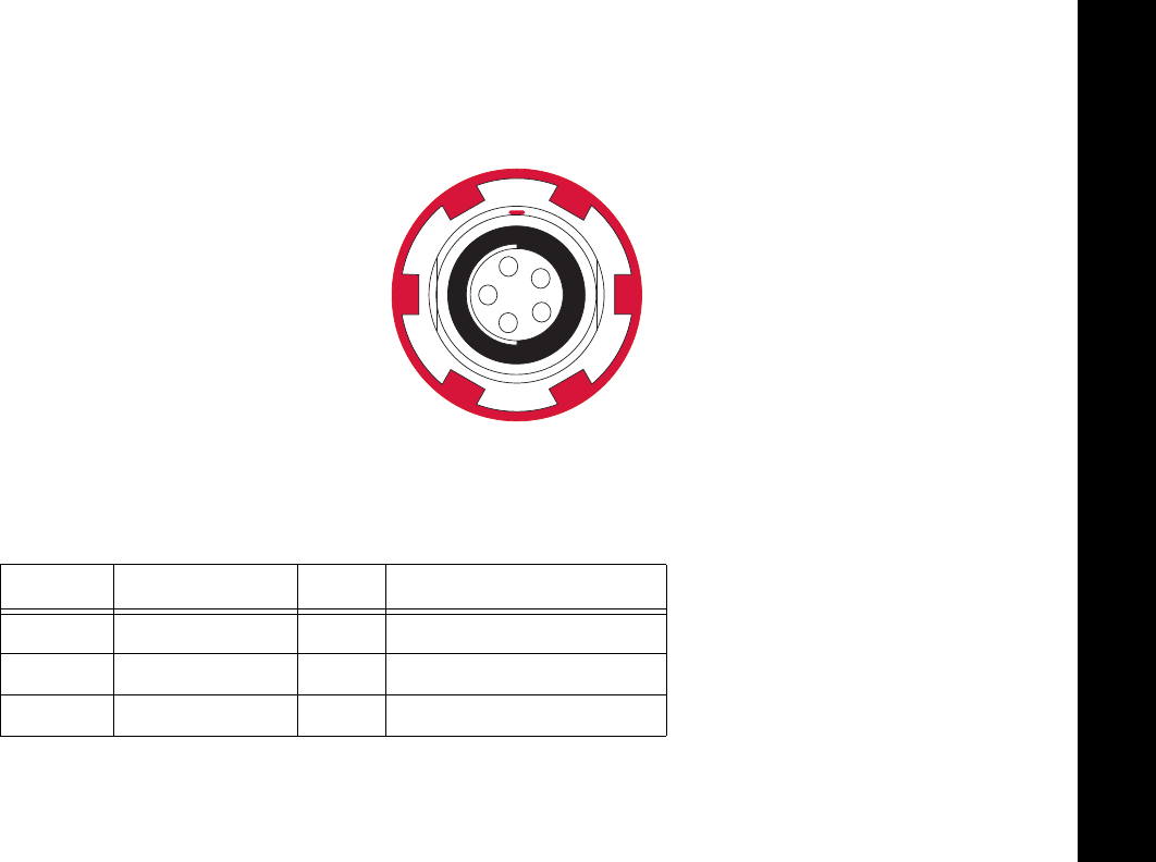
Specifications
ConnectorSpecifications
95
P/N:7010‐1004
Power Connector
Rimmedinred,thepowerconnector(Figure28)isasealedreceptacle,5pin,ODUpartnumberG80F1C‐T05QF00‐0000.
Figure 28. Power Connector
Table14describespowerconnectorspecifications.
Table 14. Power Connector Specifications
Number Signal Name Dir Details
1Power_INP P9to21voltsDCinput
2Power_INP P9to21voltsDCinput
3Power_GND PGround,powerreturn
1
2
3
45
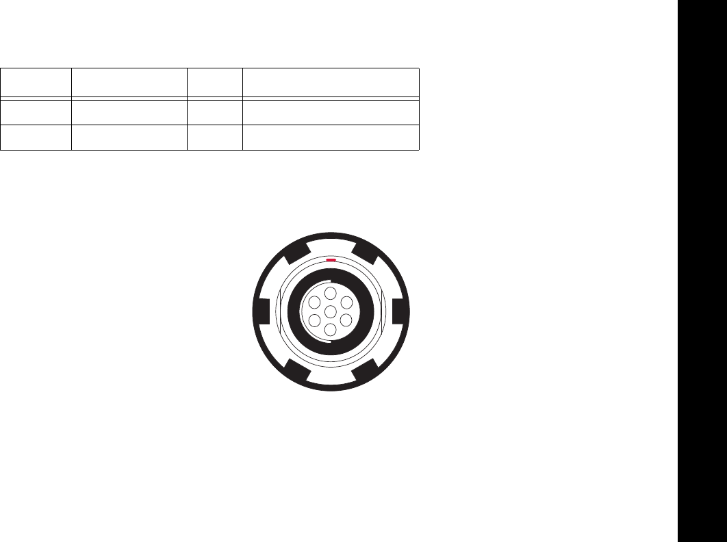
Specifications
ConnectorSpecifications
96
P/N:7010‐1004
Serial C-RS232 Connector
Rimmedinblack,theserialRS232connector(Figure29)isasealedreceptacle,7pin,ODUpartnumberG80F1C‐T07QC00‐0000.
Figure 29. Serial RS232 Connector
4Power_GND PGround,powerreturn
5Aux_Power P9to21voltsDCinput
Table 14. Power Connector Specifications (Continued)
Number Signal Name Dir Details
1
2
3
4
5
6
7

Specifications
ConnectorSpecifications
97
P/N:7010‐1004
Table15givestheRS232cableconnectorspecifications.
Table 15. RS232 Connector Specifications
Number Signal Name Dir Details
1Notused
2GND ‐Signalground
3CTS ICleartosend
4RTS ORequesttosend
5RXD IReceivedata
6TXD OTransmitdata
7Notused
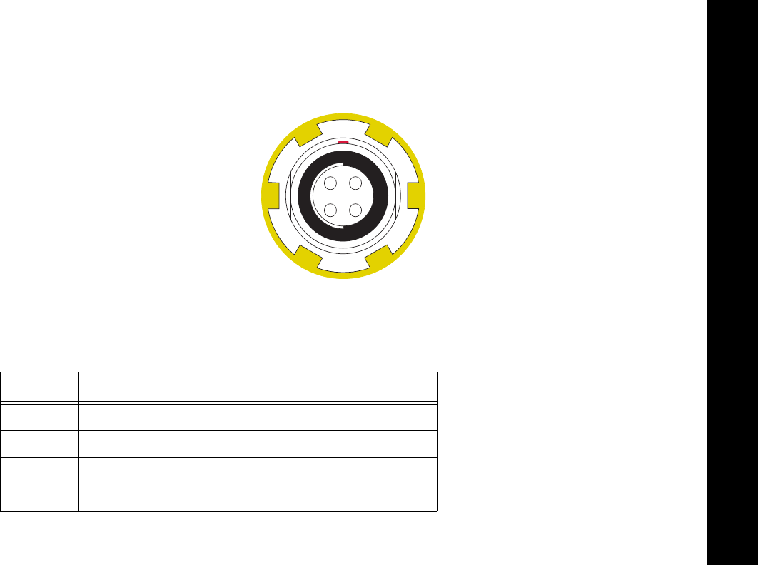
Specifications
ConnectorSpecifications
98
P/N:7010‐1004
USB Connector
Rimmedinyellow,theUSBconnectorisasealedreceptacle,4pinTPScableconnector(Figure30).
Figure 30. USB Connector for GGD Options
Table16givestheUSBconnectorspecifications.
Table 16. USB Specifications
Number Signal Name Dir Details
1USB_PWR PBuspowerinput
2USBD‐ I/O Dataminus
3USBD+ I/O Dataplus
4GND PGround
12
3 4

Specifications
Brazil‐OnlyRadioSpecifications
99
P/N:7010‐1004
Brazil-Only Radio Specifications
TheequipmentwillbecommercializedinBrazilonlywiththefollowingtechnologies(Oequipamentoserácomercializadono
Brasilapenascomasseguintestecnologias):
•
BluetoothV.2.1EDR
•
DigitalUHFII(459‐460MHze469‐470MHz)–ModulaçõesGMSKe4‐LevelFSK(4LFSK)
Table17.Brazil‐OnlyGeneralInformation
Parameter Specification
Model(Modelo) GR‐5
Description(descrição) GR‐5withDUHF(459‐460,469‐470MHzx12.5KHzspacing)+BlueTooth
Type(Tipo) TransmissorDigital‐CategoriaII

Specifications
Brazil‐OnlyRadioSpecifications
100
P/N:7010‐1004
Table18.EspecificaçõesModemUHFDigitalIIparaoBrasil
Parameter Specification
OperatingFrequencyRange
(Faixadefreqüênciadeoperação)
UHF459‐460,469‐470MHz
ModulationTechniques
(técnicasdemodulação)
GMSKand4‐LevelFSK(4LFSK)
MaximumTransmitPower
(MáximadeTransmissãodeEnergia)
1Watt
Protocols
(Protocolos)
Satel4LFSK
PDLGMSK
PDL4LFSK
TrimTalkGMSK
OccupiedBandwidth(channelspacing) 12.5KHz
DataTransmissionRateat12.5kHz
ChannelSpacing
(Taxadetransmissãodedadosde12.5
KHzcanalespaçamento)
4800,9600bps
DataSpeedofSerialInterface
(Avelocidadededadosdeinterface
serial)
Max115200bps
ForwardErrorCorrection Yes(Sim)
Scrambling Yes(Sim)

Specifications
Brazil‐OnlyRadioSpecifications
101
P/N:7010‐1004
CommunicationMode
(mododecomunicação)
Half‐Duplex(MeioDuplex)
OerationModes:
(modosdeoperação)
Transmitter(Transmissor)
Receiver(Recebedor)
Repeater(Repetidor)
Table19.MóduloBluetoothEspecificações
Parameter Specification
Range(Alcance) Upto10m(indoor),upto20m(outdoor)
[Até10m(interior),até20m(aoarlivre)]
Type(Atração) Class2
ServiceClass(ClassedeServiço) Miscellaneous(variado)
SupportProfiles(Perfisdeapoio) LM,L2CAP,SDP,SPP
FrequencyCountryCode
(FreqüênciaCódigodopaís)
NorthAmericaandEurope(AméricadoNorteeEuropa)
Table18.EspecificaçõesModemUHFDigitalIIparaoBrasil(Continued)
Parameter Specification

ProductIdentification
102
P/N:7010‐1004
• • • • • •
Product Identification
EarlierversionsoftheGR‐5receiversupported216UniversalTrackingchannels.ThenewGR‐5receiver,featuring
Vanguard™Technology,supports226channels,whicharelistedinTable20byserialnumberrange.
YoucanalsoidentifythenewGR‐5receiver,featuringVanguardTechnology,bytheserialnumberlabelonthe
receiver,whichcontainstheTopconVanguardTechnologylogo.
Table20.ProductSerialNumbers
CellularModem SerialNumber
GR‐5(WithDigitalUHFII)
Nocellularmodem 1117‐2xxxx
HSPAmodem 1118‐2xxxx
CDMAmodem 851‐2xxxx
GR‐5(WithFH915+)
Nocellularmodem 800‐2xxxx
HSPAmodem 1203‐2xxxx

SD/SDHCCardRecommendations
103
P/N:7010‐1004
• • • • • •
SD/SDHC Card Recommendations
ThissectionprovidesarecommendedlistofSD/SDHCcardsthatweretestedwiththereceiver.Thislistofrecommendationsis
basedontestingresultsavailabletodateandshouldnotbeconsideredacomprehensivelist.Thereceiveriscapableofworking
withSD/SDHCcardswithastoragecapacityofupto32GB.
TopconrecommendsusingthefollowinglistofSD/SDHCcardswithyourreceiver:
•
Swissbit®Industrial2GB
•
SanDisk®UltraII
•
Transcends®UltraIndustrial2GB
•
APRO®Industrial4GB
Foroptimalandconsistentperformance,TopconrecommendsusingtheSD/SDHCcardslistedinthissection.

SafetyWarnings
104
P/N:7010‐1004
• • • • • •
Safety Warnings
General Warnings
Topconreceiversaredesignedforsurvey/constructionandrelateduses(thatis,surveyingcoordinates,distances,
anglesanddepths,andrecordingsuchmeasurements).Thisproductshouldneverbeused:
•
Withouttheuserthoroughlyunderstandingthismanual.
•
Afterdisablingsafetysystemsoralteringtheproduct.
•
Withunauthorizedaccessories.
•
Withoutpropersafeguardsatthejobsite.
•
Contrarytoapplicablelaws,rules,andregulations.

Safety Warnings
BatteryWarnings
105
P/N:7010‐1004
Battery Warnings
Neverattempttoopenthecasingofthedetachablebatteries!Lithium‐Ionbatteriescanbedangerousif
mishandled!
Donotincinerateorheatthebatteryabove212degreesfahrenheit(100degreescelsius).Excessiveheatcan
causeseriousdamageandpossibleexplosion.
Tamperingwiththebatteriesbyendusersornon‐factoryauthorizedtechnicianswillvoidthebattery’s
warranty.
• Donotdisassemblethebatteries.
• Donotchargeinconditionsdifferentthanspecified.
• Donotuseotherthanthespecifiedbatterycharger.
• Donotshortcircuit.
• Donotcrushormodify.

Safety Warnings
ReceiverWarnings
106
P/N:7010‐1004
Receiver Warnings
Usage Warnings
Tamperingwiththereceiverbytheendusersornon‐factoryauthorizedtechnicianswillvoidthereceiver’s
warranty:
•Donotattempttoopenthereceiverandmodifyanyofitsinternalcomponents.
•Donotchargeinconditionsdifferentthanspecified.
•Donotshortcircuit.
Ifthisproducthasbeendropped,altered,transportedorshippedwithoutproperpackaging,orotherwise
treatedwithoutcare,erroneousmeasurementsmayoccur.
Theownershouldperiodicallytestthisproducttoensureitprovidesaccuratemeasurements.
InformTPSimmediatelyifthisproductdoesnotfunctionproperly.
OnlyallowauthorizedTopconwarrantyservicecenterstoserviceorrepairthisproduct.

Regulatory
107
P/N:7010‐1004
• • • • • •
Regulatory
Thefollowingsectionsprovideinformationonthisproduct’scompliancewithgovernmentregulationsforuse.
FCC Compliance
ThisequipmentcomplieswithFCCradiationexposurelimitssetforthforuncontrolledequipmentandmeetstheFCCradio
frequency(RF)ExposureGuidelinesinSupplementCtoOET65.ThisequipmenthasverylowlevelsofRFenergythatitdeemedto
complywithoutmaximumpermissiveexposureevaluation(MPE).Butitisdesirablethatitshouldbeinstalledandoperatedwith
atleast30cmandmorebetweentheradiatorandperson’sbody(excludingextremities:hands,wrists,feetandankles).
ThisequipmenthasbeentestedandfoundtocomplywiththelimitsforaClassAdigitaldevicepursuanttopart15oftheFCCrules.
Theselimitsaredesignedtoprovidereasonableprotectionagainstharmfulinterferencewhentheequipmentisoperatedina
commercialenvironment.Thisequipmentgenerates,uses,andcanradiateradiofrequencyenergyand,ifnotinstalledandused
inaccordancewiththeinstructionmanual,maycauseharmfulinterferencetoradiocommunications.Operationofthisequipment
inaresidentialareaislikelytocauseharmfulinterferenceinwhichcasetheuserwillberequiredtocorrecttheinterferenceathis
ownexpense.

Regulatory
IndustryCanadaCompliance
108
P/N:7010‐1004
Ifthisequipmentdoescauseinterferencetoradioortelevisionequipmentreception,whichcanbedeterminedbyturningthe
equipmentoffandon,theuserisencouragedtotrytocorrecttheinterferencebyoneormoreofthefollowingmeasures:
•
Reorientorrelocatethereceivingantenna.
•
Movetheequipmentawayfromthereceiver.
•
Plugtheequipmentintoanoutletonacircuitdifferentfromthattowhichthereceiverispowered.
•
Consultthedealeroranexperiencedradio/televisiontechnicianforadditionalsuggestions.
Industry Canada Compliance
ThisequipmentcomplieswithICradiationexposurelimitssetforthforuncontrolledequipmentandmeetsRSS‐102of
theICradiofrequency(RF)exposurerules.ThisequipmenthasverylowlevelsofRFenergythatitdeemedtocomply
withoutmaximumpermissiveexposureelevation(MPE).Bititisdesirablethatitshouldbeinstalledandoperatedwith
atleast30cmormorebetweentheradiatorandperson’sbody(excludingextremities:hands,wrists,feet,andankles).
Anychangesormodificationstotheequipmentnotexpresslyapprovedbythepartyresponsiblefor
compliancecouldvoidyourauthoritytooperatesuchequipment.

Regulatory
IndustryCanadaCompliance
109
P/N:7010‐1004
ThisradiotransmitterGR‐5hasbeenapprovedbyIndustryCanadatooperatewiththeantennatypeslistedbelowwith
themaximumpermissiblegainindicated.Antennatypesnotincludedinthislist,havingagaingreaterthanthe
maximumgainindicatedforthattype,arestrictlyprohibitedforusewiththisdevice.
CetémetteurradioGR‐5aétéapprouvéparIndustrieCanadapourfonctionneraveclestypesd'antenneénumérésci‐
dessousaveclegainmaximaladmissibleindiqué.Lestypesd'antennesnoninclusdanscetteliste,ayantungain
supérieuraugainmaximalindiquépourcetype,sontstrictementinterditspouruneutilisationaveccetappareil.
LAIRDMONOPOLEANTENNA
P/NANT‐DS‐B806970111014
FREQRANGE=896to970MHz
MaxGAIN=5.0dBi
NEARSONRUBBERDUCKANTENNARTNC
P/NS467TR‐04171
FREQRANGE=802to928MHz
MaxGAIN=2.0dBi

Regulatory
IndustryCanadaCompliance
110
P/N:7010‐1004
ThisclassAdigitalapparatuscomplieswithCanadianICES‐003.
Cet appareil numérique de la classe A est conforme à la norme NMB-003 du Canada.
ThisdevicecomplieswithIndustryCanadalicense‐exemptRSSstandard(s).Operationissubjecttothefollowingtwo
conditions:(1)thisdevicemaynotcauseinterference,and(2)thisdevicemustacceptanyinterference,including
interferencethatmaycauseundesiredoperationofthedevice.
Le présent appareil est conforme aux CNR d’Industrie Canada applicables aux appareils radio exempts de
licence. L’exploitation est autorisée aux deux conditions suivantes : (1) l’appareil ne doit pas produire de
brouillage, et (2) l’utilisateur de l’appareil doit accepter tout brouilage radioélectrique subi, même si le
brouillage est susceptible d’en compromettre le fonctionnement.
IC RF Radiation Exposure Statement
Wheninstalling,locateorpointthisdeviceawayfromtheinstaller,soitdoesnotemitRFfieldinexcessofHealthCanada’slimits
forthegeneralpopulation.ConsultSafetyCode6fromHealthCanada’swebsiteatwww.hc‐sc.gc.ca/rpb.

Regulatory
IndustryCanadaCompliance
111
P/N:7010‐1004
IC Additional Statement with Detachable Antennas
Thisdevice9withUHFIImodem)hasbeendesignatedtooperatewiththeantennaslistedbelowandhaveamaximumgainof
2.4dBi.Antennasnotincludedinthisorhavingagaingreaterthan2.4dBiarestrictlyprohibitedforusewiththisdevice.The
requiredantennaimpedanceis50ohms.
GR‐5UHFII2.4dBiwhipantenna
Manufacture/Type
420‐450MHzLAIRDorANTENEX/G420BN
450‐470MHzLAIRDorANTENEX/G450BN
Thedevice(withFH915modem)hasbeendesignatedtooperatewiththeantennaslistedbelowandhaveamaximumgainof
2.1dBi.Antennasnotincludedinthisorhavingagaingreaterthan2.1dBiarestrictlyprohibitedforusewiththisdevice.The
requiredantennaimpedanceis50ohms.
GR‐5FH9152.5dBiSleeveDipoleAntenna
Manufacture/Type
890‐960MHzLARSENSPDA17RP918
ConnectType:TNCmalereversepolarity
902‐928MHz
NEARSONS467xx‐915S
ConnectorType:TNCmalereversepolarity

Regulatory
CommunityofEuropeCompliance
112
P/N:7010‐1004
Community of Europe Compliance
TheproductdescribedinthismanualisincompliancewiththeR&TTEandEMCdirectivesfromtheEuropeanCommunity.
European Community Declaration of Conformity with R&TTE Directive
1999/5/EC
Thefollowingstandardswereapplied:(R&TTEDirective1999/5/EEC)
• ETSIEN300113‐2v1.5.1(2011‐11) • ETSIEN301489‐5v1.4.1(2002‐08)
• ETSIEN301489‐1v1.9.2(2011‐09) • ETSIEN301489‐17v1.5.1(2010‐10)
• ETSIEN301489‐7v1.3.1(2005‐11) • ETSIEN301511v9.0.2(2003‐03)
• ETSIEN300440‐2v1.4.1(2010‐08) • EN60950‐1:2006:+A11:2009&A1:2010
• ETSIEN300328v1.7.1(2006‐10) • EN55022:2010
• ETSIEN301489‐3v1.4.1(2002‐08) • ETSIEN301489‐24v1.5.1(2010‐10)
• ETSIEN301908‐1v5.2.1(2011‐05) • ETSIEN301908‐2v5.2.1(2011‐07)

Regulatory
CommunityofEuropeCompliance
113
P/N:7010‐1004
Thisequipmentisintendedtobemarketedinthefollowingcountries:
ListofNationalCodes:
•
ATDEMTGB
•
BEGRNLIS
•
CYHUPLLI
•
CZIEPTNO
•
DKITSKCH
•
EELVSIBG
•
FILTESRO
•
FRLUSETR
TheequipmentislabeledwithaCE!markthatinformsuserstheDIGUHFIIfrequencyrange410‐470MHzisnotharmonized
throughoutEuropeandthespecificcountryspectrumauthorityshouldbenotifiedbeforearadiomodemisused.

Regulatory
CommunityofEuropeCompliance
114
P/N:7010‐1004
Useofthisequipmentrequiresalicense.
L’impiegodiquestoimpiantonecessitaunaconcessione.
DasBetreibendieserAnlageunterliegtderKonzessionspflicht.
L’utilisationdecetteinstallationnécessiteuneconcession.

Regulatory
DeclarationofConformity(R&TTEDirective1999/5/EC)
115
P/N:7010‐1004
Declaration of Conformity (R&TTE Directive 1999/5/EC)
esky
[Czech] (Topcon) tímto prohlašuje, že tento (GR-5) je ve shod se
základními požadavky a dalšími píslušnými ustanoveními smrnice
1999/5/ES.
Dansk
[Danish] Undertegnede (Topcon) erklærer herved, at følgende udstyr
(GR-5) overholder de væsentlige krav og øvrige relevante krav i
direktiv 1999/5/EF.
Deutsch
[German] Hiermit erklärt (Topcon) dass sich das Gerät (GR-5) in
Übereinstimmung mit den grundlegenden Anforderungen und den
übrigen einschlägigen Bestimmungen der Richtlinie 1999/5/EG
befindet.
Eesti
[Estonian] Käesolevaga kinnitab (Topcon) seadme (GR-5) vastavust direktiivi
1999/5/EÜ põhinõuetele ja nimetatud direktiivist tulenevatele
teistele asjakohastele sätetele.
English Hereby, (Topcon) declares that this (GR-5) is in compliance with
the essential requirements and other relevant provisions of
Directive 1999/5/EC.
Español
[Spanish] Por medio de la presente (Topcon) declara que el (GR-5) cumple
con los requisitos esenciales y cualesquiera otras disposiciones
aplicables o exigibles de la Directiva 1999/5/CE.
Regulatory
DeclarationofConformity(R&TTEDirective1999/5/EC)
116
P/N:7010‐1004
[Greek]
Français
[French] Par la présente (Topcon) déclare que l'appareil (GR-5) est
conforme aux exigences essentielles et aux autres dispositions
pertinentes de la directive 1999/5/CE.
Italiano
[Italian] Con la presente (Topcon) dichiara che questo (GR-5) è conforme ai
requisiti essenziali ed alle altre disposizioni pertinenti stabilite dalla
direttiva 1999/5/CE.
Latviski
[Latvian] Ar šo (Topcon) deklar, ka (GR-5) atbilst Direktvas 1999/5/EK
btiskajm prasbm un citiem ar to saisttajiem noteikumiem.
Lietuvi
[Lithuanian] Šiuo (Topcon) deklaruoja, kad šis (GR-5) atitinka esminius
reikalavimus ir kitas 1999/5/EB Direktyvos nuostatas.
Nederlands
[Dutch] Hierbij verklaart (Topcon) dat het toestel (GR-5) in
overeenstemming is met de essentiële eisen en de andere
relevante bepalingen van richtlijn 1999/5/EG.
Malti
[Maltese] Hawnhekk, (Topcon), jiddikjara li dan (GR-5) jikkonforma mal-
tiijiet essenzjali u ma provvedimenti orajn relevanti li hemm fid-
Dirrettiva 1999/5/EC.

Regulatory
DeclarationofConformity(R&TTEDirective1999/5/EC)
117
P/N:7010‐1004
Magyar
[Hungarian] Alulírott, (Topcon) nyilatkozom, hogy a (GR-5) megfelel a
vonatkozó alapvetõ követelményeknek és az 1999/5/EC irányelv
egyéb elõírásainak.
Polski
[Polish] Niniejszym, (Topcon) , deklaruj, e (GR-5) spenia wymagania
zasadnicze oraz stosowne postanowienia zawarte Dyrektywie
1999/5/EC.
Português
[Portugues] (Topcon) declara que este (GR-5) está conforme com os requisitos
essenciais e outras disposições da Directiva 1999/5/CE.
Slovensko
[Slovenian] (Topcon) izjavlja, da je ta (GR-5) v skladu z bistvenimi zahtevami
in ostalimi relevantnimi doloili direktive 1999/5/ES.
Slovensy
[Slovak] (Topcon) týmto vyhlasuje, že (GR-5) spa základné požiadavky a
všetky príslušné ustanovenia Smernice 1999/5/ES.
Suomi
[Finnish] (Topcon) vakuuttaa täten että (GR-5) tyyppinen laite on direktiivin
1999/5/EY oleellisten vaatimusten ja sitä koskevien direktiivin
muiden ehtojen mukainen.
Svenska
[Swedish] Härmed intygar (Topcon) att denna (GR-5) står I
överensstämmelse med de väsentliga egenskapskrav och övriga
relevanta bestämmelser som framgår av direktiv 1999/5/EG.

Regulatory
BrazilAnatelCompliance
118
P/N:7010‐1004
Brazil Anatel Compliance
Esteequipamentooperaemcaratersecundarioistoe,naotemdireitoaprotecaocontrainterferenciaprejudicial,mesmodo
estacoesdomesmotipo,enaopodecausarinterferenciaasistemasoperandoemcaraterprimario.
•
Homologation:00719‐16‐06473

Regulatory
WEEEDirective
119
P/N:7010‐1004
WEEE Directive
ThefollowinginformationisforEU‐memberstatesonly:
Theuseofthesymbolbelowindicatesthatthisproductmaynotbetreatedashouseholdwaste.Byensuringthisproductis
disposedofcorrectly,tohelppreventpotentialnegativeconsequencesfortheenvironmentandhumanhealth,whichcould
otherwisebecausedbyinappropriatewastehandlingofthisproduct.Formoredetailedinformationaboutthetake‐backand
recyclingofthisproduct,pleasecontactasupplierwhereyoupurchasedtheproductorconsult.
Bluetooth Transmission Statements/Compliance
ThisBluetoothdeviceiscomplianttothefollowingprofilesofthecorespecversion2.1/2.1+EDR:
•
Baseband
•
HCI
•
LinkManager
•
Radio
Theradiohasbeentestedusingthemaximumantennagainof2.3dBiandtheBluetoothqualificationisvalidforanyantenna
withthesameorlessgain.

Warranty
120
P/N:7010‐1004
• • • • • •
Warranty
Topconlaserandelectronicpositioningequipmentareguaranteedagainstdefectivematerialandworkmanshipundernormaluse
andapplicationconsistentwiththisManual.Theequipmentisguaranteedfortheperiodindicated,onthewarrantycard
accompanyingtheproduct,startingfromthedatethattheproductissoldtotheoriginalpurchaserbyTopcon’sAuthorized
Dealers.
1
Duringthewarrantyperiod,Topconwill,atitsoption,repairorreplacethisproductatnoadditionalcharge.Repairpartsand
replacementproductswillbefurnishedonanexchangebasisandwillbeeitherreconditionedornew.Thislimitedwarrantydoes
notincludeservicetorepairdamagetotheproductresultingfromanaccident,disaster,misuses,abuseormodificationofthe
product.
WarrantyservicemaybeobtainedfromanauthorizedTopconwarrantyservicedealer.Ifthisproductisdeliveredbymail,
purchaseragreestoinsuretheproductorassumetheriskoflossordamageintransit,toprepayshippingchargestothewarranty
servicelocationandtousetheoriginalshippingcontainerorequivalent.Alettershouldaccompanythepackagefurnishinga
descriptionoftheproblemand/ordefect.
Thepurchaser’ssoleremedyshallbereplacementasprovidedabove.InnoeventshallTopconbeliableforanydamagesorother
claimincludinganyclaimforlostprofits,lostsavingsorotherincidentalorconsequentialdamagesarisingoutoftheuseof,or
inabilitytouse,theproduct.
1. The warranty against defects in a Topcon battery, charger, or cable is 90 days.

Glossary
121
P/N:7010‐1004
• • • • • •
Glossary
B
BaseStation
–AGNSSreceiversetupoveraknownpoint,whichisusedtoderivecorrectioninformationfornearbyRover(mobile)
GNSSreceivers.
BeiDou
–BeiDouNavigationSatelliteSystemmaintainedandoperatedbyChina.
Bluetooth®–
Oftenusedinplaceofcables,Bluetoothisopenwirelesstechnologyforexchangingdataovershortdistancesfrom
fixedandmobiledevices.
G
GALILEO
–ThesatellitesystemcurrentlybeingmaintainedandoperatedbytheEuropeanUnion(EU)andEuropeanSpaceAgency
(ESA).
GGD
–GPS+GLONASSDualFrequencysignaltracking.
GLONASS–
TheGlobalNavigationSatelliteSystemmaintainedandoperatedbytheRussianFederation.
GNSS–
GlobalNavigationSatelliteSystems,suchasGPSandGLONASS.
GPS–
TheGlobalPositioningSystemmaintainedandoperatedbytheUnitedStatesDepartmentofDefense.

Glossary
122
P/N:7010‐1004
L
L1andL2
–Fortherangingcodesandnavigationmessagetotravelfromthesatellitetothereceiver,theymustbemodulated
ontoacarrierfrequency.InthecaseoftheGPSdesign,twofrequenciesareutilized:oneat1575.42MHz(10.23MHzx154)
calledL1andtheotherat1227.60MHz(10.23MHzx120),calledL2.
Light‐EmittingDiode(LED)
–Usedasindicatorlightsonthereceivertodisplaythestatusofthereceiver’scomponentsand
controlreceiveroperations.
M
MAGNETField™
–DatacontrollersoftwarethatispartoftheMAGNETsoftwaresystem.
MAGNETOffice™
–Post‐processingandCADsolutionsoftwareforsurveyingandgradeapplication.ItispartoftheMAGNET
softwaresystem.
MINTER–
Thereceiver’sMinimumINTERfaceusedtodisplayandcontroldatainputandoutput.
N
NetworkRTK–
CollectssatelliteobservationsfromthereferencestationswithinthenetworkandsendsRTKcorrectionstothe
Rover.
O
OptionAuthorizationFile(OAF)–
ThisenablesspecificfeaturesforscalableperformanceofTopconGNSSreceivers.

Glossary
123
P/N:7010‐1004
P
PhaseCenterofAntenna
–Thepointfromwhichtheelectromagneticradiationspreadssphericallyoutward,withthephaseof
thesignalbeingequalatanypointonthesphere.
Pocket‐3D–
FielddatacollectionsoftwarebyTopconforconstructionmarkets.
R
Real‐TimeKinematic(RTK)–
Aprecisemethodofreal‐timesurveying.RTKenablesyoutocheckthemeasurementquality
withouthavingtoprocessthedata.
RootMeanSquare(RMS)
–Statisticalmeasureofthemagnitudeofavaryingquantity.
Rover–
AmobileGNSSreceiveranddatacollectorusedfordetermininglocationinthefield.
S
Satellite‐BasedAugmentationSystems(SBAS)–
Complementsexistingglobalnavigationsystems.SBAStransmitsdifferential
correctionsandmessagesfornavigationsatellitesthatarewithinsightofanetworkorreferencestationsinawidearea,such
asacontinent.
StaticSurvey–
Locationdeterminationwhenthereceiver’santennaisstationary.Thismethodprovidesthehighestaccuracy
andrequiresthelongestobservationtimes.
T
TopconReceiverUtility(TRU)–
Receiverconfigurationsoftwareforreceiversandperipheraldevices.TRUisincludedonthe
GPS+SoftwareCDthataccompaniedyourreceiver.

Glossary
124
P/N:7010‐1004
U
UniversalSerialBus(USB)–
Aconnectionstandardusedbydevices,suchasareceiver,controller,computer,etc.
