Topcon America F90901 GPSS receiver with 900MHz and Bluetooth radio User Manual GR 5 OM
Topcon America Corporation GPSS receiver with 900MHz and Bluetooth radio GR 5 OM
Contents
- 1. User Manual
- 2. Op Manual
User Manual

GR-5
Operator’s Manual
PartNumber7010Ͳ1004
RevC
©CopyrightTopconPositioningSystems,Inc.
April,2013
AllcontentsinthismanualarecopyrightedbyTopconPositioningSystems,Inc.Allrightsreserved.
Neednewone

Preface
i
P/N:7010Ͳ1004
• • • • • •
Preface
ThankyouforpurchasingthisTopconproduct.ThematerialsavailableinthisManual(the“Manual”)havebeenpreparedby
TopconPositioningSystems,Inc.(“TPS”)forownersofTopconproducts,andaredesignedtoassistownerswiththeuseofthe
receiveranditsuseissubjecttothesetermsandconditions(the“TermsandConditions”).
Terms and Conditions
Use
Thisproductisdesignedtobeusedbyaprofessional.Theusershouldhaveagoodknowledgeofthesafeuseoftheproductand
implementthetypesofsafetyproceduresrecommendedbythelocalgovernmentprotectionagencyforbothprivateuseand
commercialjobsites.
Pleasereadthetermsandconditionscarefully.

Preface
TermsandConditions
ii
P/N:7010Ͳ1004
Copyrights
AllinformationcontainedinthisManualistheintellectualpropertyof,andcopyrightedmaterialofTPS.Allrightsarereserved.
Donotuse,access,copy,store,display,createderivativeworksof,sell,modify,publish,distribute,orallowanythirdpartyaccess
to,anygraphics,content,informationordatainthisManualwithoutTPS’expresswrittenconsentandmayonlyusesuch
informationforthecareandoperationofthereceiver.TheinformationanddatainthisManualareavaluableassetofTPSand
aredevelopedbytheexpenditureofconsiderablework,timeandmoney,andaretheresultoforiginalselection,coordination
andarrangementbyTPS.
Trademarks
GRͲ5,TRU™,Magnet™,PocketͲ3D™,Topcon®andTopcon PositioningSystems™aretrademarksorregisteredtrademarksofTPS.
Windows®isaregisteredtrademarkofMicrosoftCorporation.TheBluetooth®wordmarkandlogosareownedbyBluetooth
SIG,Inc.andanyuseofsuchmarksbyTopconPositioningSystems,Inc.isusedunderlicense.Otherproductandcompanynames
mentionedhereinmaybetrademarksoftheirrespectiveowners.
Disclaimer of Warranty
EXCEPTFORANYWARRANTIESINANAPPENDIXORAWARRANTYCARDACCOMPANYINGTHEPRODUCT,THISMANUALAND
THERECEIVERAREPROVIDED“ASͲIS.”THEREARENOOTHERWARRANTIES.TPSDISCLAIMSANYIMPLIEDWARRANTYOF
MERCHANTABILITYORFITNESSFORANYPARTICULARUSEORPURPOSE.TPSANDITSDISTRIBUTORSSHALLNOTBELIABLEFOR
TECHNICALOREDITORIALERRORSOROMISSIONSCONTAINEDHEREIN;NORFORINCIDENTALORCONSEQUENTIALDAMAGES
RESULTINGFROMTHEFURNISHING,PERFORMANCEORUSEOFTHISMATERIALORTHERECEIVER.SUCHDISCLAIMED
DAMAGESINCLUDEBUTARENOTLIMITEDTOLOSSOFTIME,LOSSORDESTRUCTIONOFDATA,LOSSOFPROFIT,SAVINGSOR
REVENUE,ORLOSSOFTHEPRODUCT’SUSE.INADDITIONTPSISNOTRESPONSIBLEORLIABLEFORDAMAGESORCOSTS

Preface
TermsandConditions
iii
P/N:7010Ͳ1004
INCURREDINCONNECTIONWITHOBTAININGSUBSTITUTEPRODUCTSORSOFTWARE,CLAIMSBYOTHERS,INCONVENIENCE,OR
ANYOTHERCOSTS.INANYEVENT,TPSSHALLHAVENOLIABILITYFORDAMAGESOROTHERWISETOYOUORANYOTHER
PERSONORENTITYINEXCESSOFTHEPURCHASEPRICEFORTHERECEIVER.
License Agreement
UseofanycomputerprogramsorsoftwaresuppliedbyTPSordownloadedfromaTPSwebsite(the“Software”)inconnection
withthereceiverconstitutesacceptanceoftheseTer msandConditionsinthisManualandanagreementtoabidebythese
TermsandConditions.Theuserisgrantedapersonal,nonͲexclusive,nonͲtransferablelicensetousesuchSoftwareunderthe
termsstatedhereinandinanycaseonlywithasinglereceiverorsinglecomputer.YoumaynotassignortransfertheSoftware
orthislicensewithouttheexpresswrittenconsentofTPS.Thislicenseiseffectiveuntilterminated.Youmayterminatethe
licenseatanytimebydestroyingtheSoftwareandManual.TPSmayterminatethelicenseifyoufailtocomplywithanyofthe
TermsorConditions.YouagreetodestroytheSoftwareandmanualuponterminationoftheuseofthereceiver.Allownership,
copyrightandotherintellectualpropertyrightsinandtotheSoftwarebelongtoTPS.Iftheselicensetermsarenotacceptable,
returnanyunusedsoftwareandmanual.
Confidentiality
ThisManual,itscontentsandtheSoftware(collectively,the“ConfidentialInformation”)aretheconfidentialandproprietary
informationofTPS.YouagreetotreatTPS’ConfidentialInformationwithadegreeofcarenolessstringentthatthedegreeof
careyouwoulduseinsafeguardingyourownmostvaluabletradesecrets.Nothinginthisparagraphshallrestrictyoufrom
disclosingConfidentialInformationtoyouremployeesasmaybenecessaryorappropriatetooperateorcareforthereceiver.
SuchemployeesmustalsokeeptheConfidentialityInformationconfidential.Intheeventyoubecomelegallycompelledto
discloseanyoftheConfidentialInformation,youshallgiveTPSimmediatenoticesothatitmayseekaprotectiveorderorother
appropriateremedy.

Preface
TermsandConditions
iv
P/N:7010Ͳ1004
Website; Other Statements
NostatementcontainedattheTPSwebsite(oranyotherwebsite)orinanyotheradvertisementsorTPSliteratureormadeby
anemployeeorindependentcontractorofTPSmodifiestheseTerms andConditions(includingtheSoftwarelicense,warranty
andlimitationofliability).
Safety
Improperuseofthereceivercanleadtoinjurytopersonsorpropertyand/ormalfunctionoftheproduct.Thereceivershould
onlyberepairedbyauthorizedTPSwarrantyservicecenters.UsersshouldreviewandheedthesafetywarningsinanAppendix.
Miscellaneous
TheaboveTermsandConditionsmaybeamended,modified,superseded,orcanceled,atanytimebyTPS.TheaboveTermsand
Conditionswillbegovernedby,andconstruedinaccordancewith,thelawsoftheStateofCalifornia,withoutreferenceto
conflictoflaws.

Preface
TermsandConditions
v
P/N:7010Ͳ1004
Manual Conventions
Thismanualusesthefollowingconventions:
Convention Description Example
Bold Menu,ordropͲdownmenuselection File
Exit(ClicktheFilemenuandclickExit)
Nameofadialogboxorscreen FromtheConnectionscreen...
Buttonorkeycommands ClickFinish.
Mono Usersuppliedtextorvariable Typeguest,andclickEnter.
Italic ReferencetoanothermanualorhelpdocumentRefertotheTopconReferenceManual.
Furtherinformationtonoteaboutsystemconfiguration,maintenance,orsetup.
Supplementaryinformationthatcanhaveanadverseaffectonsystemoperation,systemperformance,data
integrity,measurements,orpersonalsafety.
Notificationthatanactionhasthepotentialtoresultinsystemdamage,lossofdata,lossofwarranty,or
personalinjury.

• • • • • •
Table of Contents
i
P/N:7010Ͳ1004
TermsandConditions...................................................................i
Use..............................................................................i
Copyrights........................................................................i
i
Trademarks.......................................................................i
i
DisclaimerofWarranty..............................................................i
i
LicenseAgreement.................................................................iii
Confidentiality.....................................................................iii
Website;OtherStatements..........................................................i
v
Safety............................................................................i
v
Miscellaneous.....................................................................i
v
ManualConventions................................................................v
GRͲ5Features.........................................................................2
UnpackingYourReceiverKit .............................................................3
ii
P/N:7010Ͳ1004
SuppliedSystemComponents........................................................3
Accessories.......................................................................4
TechnicalDocuments...................................................................5
UsingTopconSoftwareWithYourReceiver .................................................5
GettingTechnicalSupport...............................................................6
Website..........................................................................7
ReceiverOverview .....................................................................8
Cables................................................................................9
Accessories ...........................................................................11
Batteries..............................................................................13
DataandPowerPorts...................................................................14
ExternalRadioAntennaConnector ........................................................15
BottomConnector .....................................................................16
SD/SDHCandSIMCardSlots.............................................................17
SIMCardSlot......................................................................1
8
RecommendedSIMCards........................................................1
8
InstallingtheSIMCard...........................................................18
iii
P/N:7010Ͳ1004
PowerButton .........................................................................20
FUNCTIONButton/LoggingData..........................................................21
BatteryLED ...........................................................................25
ReceiverStatusLEDs....................................................................26
RXTXLED.........................................................................2
6
STATLED.........................................................................2
8
RECLED..........................................................................2
8
BluetoothLED.....................................................................2
9
TurningOn/OfftheReceiver.............................................................30
PoweringtheReceiver..................................................................30
DetachableExternalBatteries........................................................3
1
ChargingtheBatteries...........................................................3
2
ChargingTemperatures..........................................................3
6
ChargingProcedure.............................................................3
6
LeavingtheBatteriesonCharge...................................................37
AttachingtheBatteries..........................................................3
8
DetachingtheBatteries..........................................................3
9
AssemblingtheAABatteryShell...................................................39
iv
P/N:7010Ͳ1004
SurveyingWhileCharging........................................................40
ChangingtheBatterieswhileSurveying.............................................4
1
UsinganAuxiliaryPowerSource......................................................41
InsufficientPower ......................................................................44
ViewingReceiverInformation............................................................45
LoadingNewFirmware..................................................................47
AbouttheOAF.........................................................................50
CheckingtheReceiver’sOAF.........................................................5
1
LoadinganOAF....................................................................5
2
ClearingtheNVRAM ....................................................................55
SettingUptheBaseReceiver .............................................................57
SettingUptheRoverReceiver ............................................................58
MeasuringAntennaHeight ..............................................................59
Memory ..............................................................................61
SD/SDHCCard.....................................................................62
RecommendedSD/SDHCCards....................................................6
2
InstallingtheSD/SDHCCard......................................................6
3
v
P/N:7010Ͳ1004
InitializingtheFileSystem...........................................................63
InitializingtheFileSystemUsingTRU...............................................6
4
SettingRecordingParameters ............................................................64
LoggingRates..........................................................................64
RecordingData ........................................................................65
ManagingFiles.........................................................................66
DownloadingandDeletingFiles.......................................................6
6
CheckThisFirst! .......................................................................68
PoweringProblems.....................................................................69
ReceiverProblems .....................................................................70
BluetoothProblems ....................................................................74
TRUProblems .........................................................................76
CleaningandStoringtheReceiver.........................................................77
GettingCustomerSupport ...............................................................77
GeneralDetails ........................................................................78
GPSBoardDetails......................................................................90
BluetoothModuleDetails ...............................................................92
vi
P/N:7010Ͳ1004
ConnectorSpecifications ................................................................93
Radio(Modem)RFConnector........................................................9
3
PowerConnector...................................................................9
4
SerialCͲRS232Connector............................................................9
6
USBConnector.....................................................................9
7
GeneralWarnings.....................................................................99
BatteryWarnings ......................................................................100
ReceiverWarnings .....................................................................101
UsageWarnings.......................................................................101
FCCCompliance........................................................................102
IndustryCanadaCompliance .............................................................103
ICRFRadiationExposureStatement...................................................104
ICAdditionalStatementwithDetachableAntennas...................................... 104
CommunityofEuropeCompliance........................................................105
EuropeanCommunityDeclarationofConformitywithR&TTEDirective1999/5/EC............ 105
DeclarationofConformity(R&TTEDirective1999/5/EC)......................................106
WEEEDirective ........................................................................110
vii
P/N:7010Ͳ1004
BluetoothTransmissionStatements/Compliance............................................110
KoreanKCͲRFCompliance ...............................................................111

Introduction
1
P/N:7010Ͳ1004
• • • • • •
Introduction
Topcon’sGRͲ5receiverisacompactandlightweightGNSSreceiverforstaticandkinematicapplications.Thereceiverdesign
includesaGNSSreceiverboardbasedonVanguard™technology,whichprovidesunlimitedtrackingability.TheGRͲ5delivers
worldͲclasspositioningandnavigationcapabilitytoyourapplicationbytrackingsignalsfrommultiͲconstellationsatellitesystems,
includingGPS,GLONASS,andSBAS.
Usingafullwaveantenna,theGRͲ5canreceiveandprocessesmultiplesignaltypes,includingthelatestGPSL2CandGLONASSC/A
L2,GPSL5andGALILEO
1
signals.DrivenbytheaugmentedParadigm
™
G3chip,theboardprovides216universalchannelsand
upto100Hzpositionandmeasurementupdaterates.
GNSStrackingcapabilities,dualͲfrequencyRTK,SBASfunctionality,extensivecommunicationcapabilities,removablememoryfor
filescombinetoprovideapositioningsystemefficient,secure,andappropriateforanysurvey.
Severalotheruniquefeatures,includingmultipathmitigation,adjustablephaseͲlockedloop(PLL)anddelayͲlockedloop(DLL)
parameters,offerareliableandversatilereceptionofweaksignalsevenindegradedsignalenvironments.Thereceiverprovides
thefunctionality,availability,andintegrity.
TheGRͲ5offerscompleteIP67protectionagainstdustandwateringress,inadditiontosuperiorvibrationandshockresistance.
TheTopconcommunicationinterfaceallowsyoutoquicklyintegrateTopcon’spremiumGNSSperformancewithinnewsystems
andquicklydeliverworldͲclasspositioningandnavigationsupporttoyourapplications.
1. The GR-5 tracks the GIOVE-A and GIOVE-B test satellites. The signals from these satellites are used for signal evaluation and test
purposes only.
Introduction
GRͲ5Features
2
P/N:7010Ͳ1004
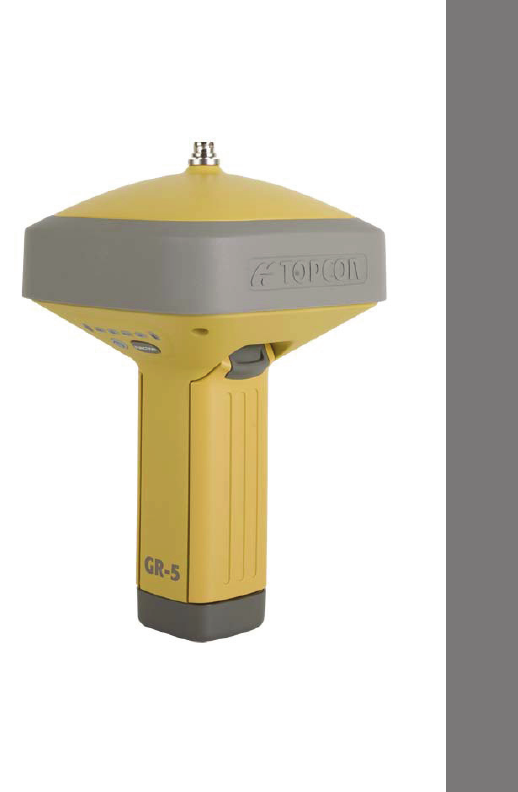
GR-5 Features
TheGRͲ5receiver’sadvanceddesignreducesthenumberofcables
requiredforoperation,allowingforasimplifiedsetupandlessparts
tokeeptrackof.TheGRͲ5receiverfeaturesthefollowing:
•
Twoexternal,detachablebatteries
•
USBandserialdataports
•
Externalmemorycardslot
•
Internalradiomodem
•
Bluetooth®wirelesstechnologymodule
•
Interfaceforcontrollingviewingdataloggingthroughthe
LEDdisplay
•
SIMcardslot
TheGRͲ5canbeconfiguredinavarietyofways,dependingonyour
projectrequirements.Typically,theGRͲ5supportsthefollowing
operationmodes:
•
StaticpostͲprocessing
•
BaseandRoverRTK
•
NetworkRoverRTK
•
SBASͲenablednavigation
Figure1:GRͲ5Receiver
Introduction
UnpackingYourReceiverKit
3
P/N:7010Ͳ1004
Unpacking Your Receiver Kit
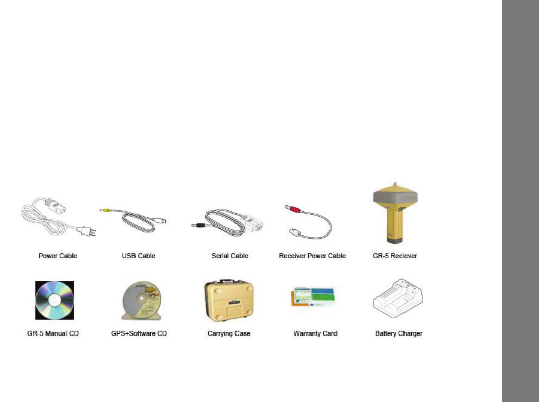
Thissectiondescribesthedocumentation,standardkitcomponents,andaccessories(dependingonyourpurchase)that
accompanyyourreceiver.Whenyouunpackyourreceiverkit,verifyyoureceivedtheitemslistedinthissection.Ifanyitems
aremissingordamaged,contactyourTopcondealerorTopco ntechnicalsupport.See“GettingTechnicalSupport”onpage 6.
•
StandardcomponentsareillustratedinFigure 2.
•
ReceiveraccessoriesareillustratedinFigure 3.
•
Receiverdocumentationislistedonpage 5.
Supplied System Components
Figure2:StandardSystemComponentsthatareIncludedwithYourReceiver
Introduction
UnpackingYourReceiverKit
4
P/N:7010Ͳ1004
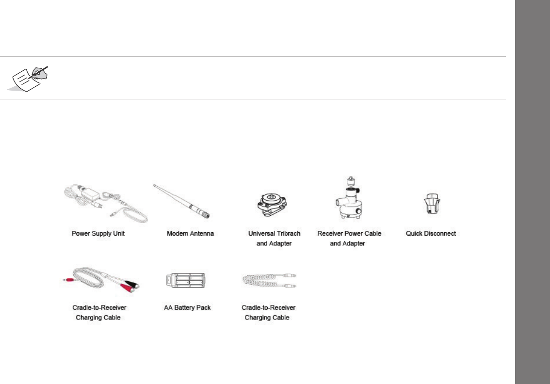
Accessories
Topconoffersawidevarietyofaccessories(seeFigure 3)speciallydesignedtoimprovesystemflexibilityandjobsiteefficiency.
FormoredetailsontheoptionalaccessoriesavailableforGRͲ5,contactyourTopcondealer.
Figure3:ReceiverAccessories
TheGPS+SoftwareCDincludesUSBdrivers,whichyouneedtoinstalltousetheUSBportfor
communications.

Introduction
TechnicalDocuments
5
P/N:7010Ͳ1004
Technical Documents
TheGRͲ5ManualCDincludestwomanuals(listedbelow)thathelpyousetupanduseyournewreceiverquicklyandefficiently.
•
GRͲ5Operator’sManual–AnonͲscreenhelpdocumentthatcontainsdetailedinformationonhowtouseyournew
receiver.
•
TopconReceiverUtility(TRU)ReferenceGuide–AnonͲscreenhelpdocumentthatcontainsdetailedinformationonhow
tousetheTRUsoftwareincludedontheGPS+SoftwareCD.FormoreinformationabouttheTRUsoftware,see“Using
TopconSoftwareWithYourReceiver”.
Using Topcon Software With Your Receiver
UsetheGRͲ5receiverinconjunctionwiththeTopcon ReceiverUtility(TRU)andMAGNETField™orPocketͲ3Dapplicationsfor
aprecisionpositioningsolution.Topconsoftwareenablesyoutoconfigurethereceiverandotherexternaldevices,managefiles,
collectdata,andperformsurveyandconstructionworkflows.
TheTopcon ReceiverUtility(TRU)isahardwareconfigurationsoftwareforreceiversandperipheraldevices.Youcaninstalliton
desktopcomputersanddatacontrollers.ThisprogramisprovidedontheGPS+SoftwareCDthataccompaniedyourreceiver.A
TRUhelpdocumentisprovidedontheGRͲ5CD.
Topcon’sMAGNETField™softwarefordatacontrollersprovidesrealͲtimecommunication,cloudstorage,datacollectionand
exchange,andfieldsolutions,suchastopo,staking,roads,calculations,andmore.ContactyourTopcondealerformore
informationaboutMAGNETFieldandtheentireMAGNETEnterprisesystem.
PocketͲ3DisaprogramthatrunsondatacontrollerswithWindowsCE®andmobileplatforms.PocketͲ3Dsimplifiesdata
collection,allowingyoutocheckcutsandfills,layoutpointsandsurveyallorpartofthejobsitequicklyandefficiently.Contact
yourTopcondealerformoreinformationaboutPocketͲ3D.

Introduction
GettingTechnicalSupport
6
P/N:7010Ͳ1004
Getting Technical Support
BeforecontactingaTopcon customerrepresentativeaboutanyproblemswiththereceiver,see“Troubleshooting”onpage 68
forsomesolutionsthatmayfixtheissue.
ContactyourlocalTopcondealerorvisittheTopconTotalCareWebsite(www.TopconTotalCare.com)fortechnicalsupport.
WhencontactingTopcon fortechnicalassistance,providethefollowinginformationforbetterandfasterservice:
1. Adescriptionofthefollowing:
–Fieldoperationthatwasbeingperformedwhentheproblemoccurred
–Detailsoftheunexpectedbehavior,symptoms,andanyerrormessagesthatprecedeorfollowtheproblem
–Problemoccurrencefrequencyorpatterns
2. Receiverinformationandconfigurationsettings.Forreceiverinformation,clickInformationinTRU,selectSaveto
File,enterafilename,andsaveittothecomputer.
3. Specificationsofmobiledevicesandcomputersusedinthefieldorofficeexhibitingtheproblem.These
specificationsshouldincludemodelinformation,versionnumber,operatingsysteminformation,memoryand
storagecapacity,etc.
4. Informationaboutthesystemsoftware,includingtheversionnumberandstepstoreproducetheproblem.
5. Adescriptionofthefieldenvironmentand/orobservationconditionswhentheproblemoccurred.
Forquickandeffectivesupport,provideadetaileddescriptionoftheproblem.

Introduction
GettingTechnicalSupport
7
P/N:7010Ͳ1004
Website
TheTopconwebsiteprovidescurrentinformationaboutTopcon’slineofproducts.Thesupportareaofthewebsiteprovides
accesstoTopconfieldandofficesoftware,manuals,frequentlyaskedquestions,andsoforth.ToaccesstheTopco nwebsite,
visitwww.topconpositioning.com.
TheTopcon’sTo talCarewebsitealsoprovidescompletesupport,suchasnews,updates,reminders,training,liveWebinars,and
customerservicetohelpyougettheinformationyouneed.Visitwww.topcontotalcare.com.

GettingAcquainted
8
P/N:7010Ͳ1004
• • • • • •
Getting Acquainted
TheGRͲ5receiverenclosureisfullysealedandincorporatestheGNSSreceiverboard,antenna,batteries,memorystorage,
andwirelesscommunicationdevice.
Receiver Overview
TheupperportionofthereceivercontainstheGNSSantenna,whichisenclosedbytheradomeandsecurelysurroundedby
ashockͲabsorbingrubberbumper.Thereceiver’smagnesiumalloylowerenclosurefeaturesaneasyͲtoͲoperatedisplay
panel,detachablebatteries,quickreleasemountingsocket,anddataports.
TheGRͲ5receiverhasahighlyͲvisibledisplaypanelwithsingleͲbuttonoperation.Thedisplaypanelenablesyoutoviewthe
receiver’soperationalstatus.Formoreinformation,see“DisplayPanelOperations”onpage 19.
Youcanlocateregulatoryandproductidentificationinformationonthetworeceiverlabels,whicharelocatedinsideofthe
batterycompartments.Theproductidentificationlabelcontainstheserialnumberandpartnumber.
Getting Acquainted
Cables
9
P/N:7010Ͳ1004
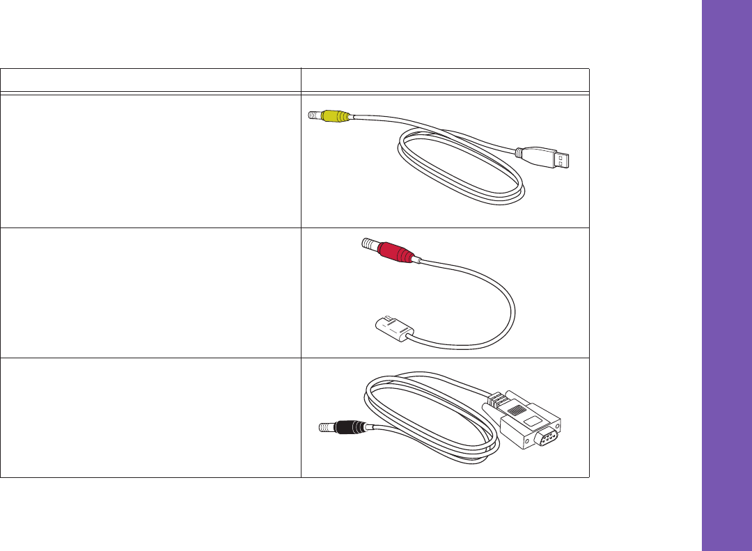
Cables
TheGRͲ5packageincludesapowersupplycable,aUSBcable,andapoweradapter.Table 1describesthecablesincluded
withyourreceiver.
Alignthekeywayswhenconnectingthepower/serialcabletothereceiverport.Turnthecablelockclockwise
untilitclickstosecurethecableinplace.Todisconnectthecable,turnthelockcounterͲclockwise,andthen
gentlyremovethecable.
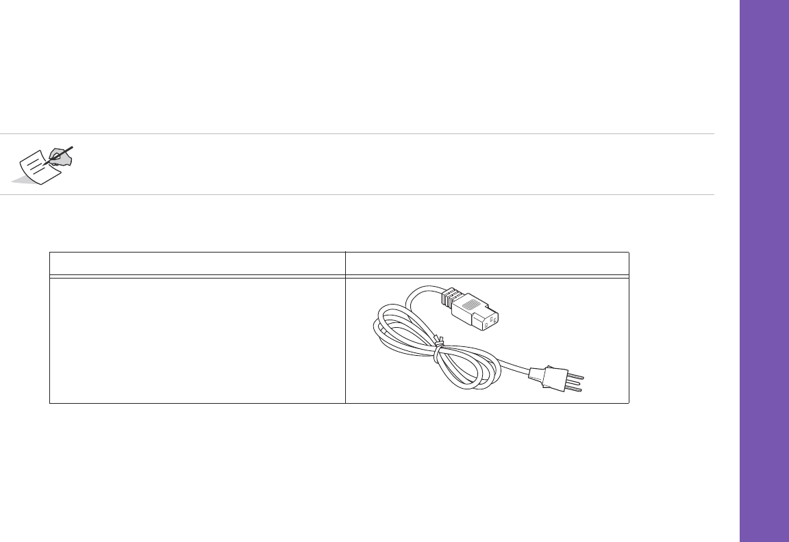
Table1.ReceiverCables
Cable Description Cable Illustration
PowerCable
Connectsthepowersupplyunittoagroundedoutlet.
U.S.:p/n:14Ͳ008052Ͳ01
Eur:p/n:14Ͳ008054Ͳ01
Aus.:p/n:14Ͳ008053Ͳ01
Getting Acquainted
Cables
10
P/N:7010Ͳ1004
USBCable
Connectsthereceivertoanexternaldevice(controlleror
computer)fordatatransferandreceiverconfiguration.
p/n14Ͳ008070Ͳ01
ReceiverPower/ChargingCable
ConnectsthereceiverandthepowersupplyunitviaSAE
connectorsforbatterycharging.
p/n14Ͳ008016Ͳ03
SerialCable
Connectsthereceivertoanexternaldevice(controlleror
computer)fordatatransferandreceiverconfiguration.
p/n:14Ͳ008005Ͳ02
Table1.ReceiverCables
Cable Description Cable Illustration

Getting Acquainted
Accessories
11
P/N:7010Ͳ1004
Accessories
Topcon offersawidevarietyofaccessoriesspeciallydesignedtoimprovesystemflexibilityandjobsiteefficiency.Formore
detailsabouttheavailableaccessories,contactyourTop condealer.
•
PowerSupplyUnit
(p/n22Ͳ034101Ͳ01):chargesthedetachablebatterieswhenconnectedtoagroundedoutlet.This
unitconvertsthealternatingcurrent(AC)normallysuppliedfromanelectricaloutlettoadirectcurrent(DC)usedto
chargethebatteriesand/orpowerthereceiver.
Thepowersupplyunitcaneitherbeconnectedtothechargingcradleordirectlytothereceiver.Fordetails,seethe
powerrelatedsectionsin“PowerSupplyUnit”onpage 33.
•
TheModemAntenna
:SpreadSpectrumorUHFantennaincludessupportforaGSM/HSPAmodem.
TheSpreadSpectrumantennaisareversepolarityTNCRFconnection(p/n30Ͳ030012Ͳ01)andaUHFantennaisaBNC
connection(p/n30Ͳ070003Ͳ01UHF410Ͳ440orp/n30Ͳ050503Ͳ01UHF450Ͳ470).
•
The2mFixedHeightTripodandPole
:Aheavydutytripod(22Ͳ050501Ͳ01).
•
Theuniversaltribrachandtribrachadapter
1
(p/n22Ͳ006008Ͳ01andp/n22Ͳ006009Ͳ011):areusedtolevelthetripod
andsecurethereceiverorantennatothetripod.
•
Theprecisiontribrachadapter
:isusedtopreciselycenter,align,andlevelthetripodoverapoint.Thehorizontalspacer
(p/n60419)insertsintotheprecisiontribrachandallowsthereceivertositsecurelyontheprecisiontribrach.
Thepowersupplyunitshouldonlybeusedforchargingthebatteries.Donotuseasapowersource
duringsurveying.
1. The universal tribrach and tribrach adapter is not needed when using the heavy duty tripod (22-050501-01).

Getting Acquainted
Accessories
12
P/N:7010Ͳ1004
•
Thequickdisconnectadapter
(p/n02Ͳ850905Ͳ01):connectstotherangepoleforthereceivertoslipintothetop.Using
thesideclips,thereceivercanbequicklyconnectedto/disconnectedfromtherangepole.
•
AhandͲheldcontroller
:allowstheGRͲ5BaseandRoversystemstobeconfiguredandmonitoreddirectlyinthefield.
YoucanusetheTopconReceiverUtility(TRU)toconfigurethereceiverandanyTopconfielddatacollectionsoftware.
•
MAGNETandPocket3DSoftware
:canbeusedtooperatethereceiver.SeereferencemanualofTRUorFielddata
collectionsoftwarefordetailsonsetupandoperation.
•
TheODUͲtoͲalligatorclipscable
(p/n14Ͳ008097Ͳ01LF):connectsthechargingcradleorreceivertoanauxiliarybattery
forpoweringthereceiverduringsurveyoperations.
•
TheAAbatterypack
:holdsfourAAbatteriestoprovideaportablebackuppowersourceforthereceiver.Dueto
variancesinAAbatterycapacity,andthemodeofthereceiverandtypeofmodem,theamountoftimethereceiveris
poweredvaries.See“AssemblingtheAABatteryShell”onpage 12fordetailsonhowtoattachthepacktotheGRͲ5.
•
CradleͲtoͲreceiverchargingcable
(p/n14Ͳ008072Ͳ01(1.5mlong)p/n14Ͳ008072Ͳ02(0.5mlong):Connectsthereceiver
tothechargingcradleforexternalpower.
•
BatteryRecharger
(01Ͳ050911Ͳ01):Chargesthebatteries.See“ChargingtheBatteries”onpage 5.
DonotuserechargeableAAbatteries.
DonotusetheAAbatteryshellwhentheradiomodemisintransmittermode.
Getting Acquainted
Batteries
13
P/N:7010Ͳ1004
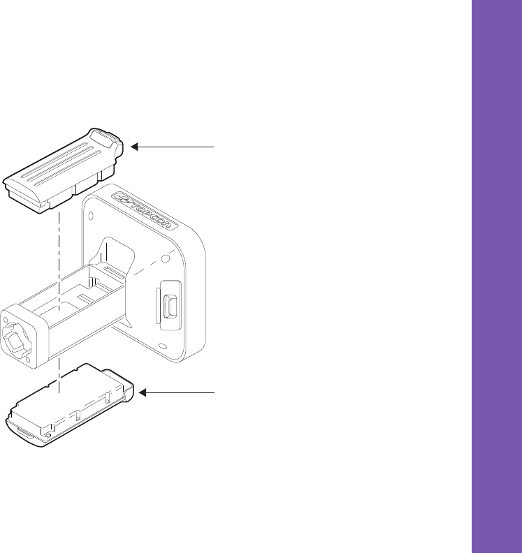
Batteries
Thereceivercomesequippedwithtwodetachable,rechargeablebatteriesforpoweringthereceiver.Formore
informationaboutusingthebatteries,see“ManagingPower”onpage 30.
Figure4:GRͲ5DetachableBatteries
Detachable
Battery
Detachable
Battery
Getting Acquainted
DataandPowerPorts
14
P/N:7010Ͳ1004
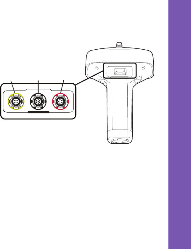
Data and Power Ports
TheGRͲ5hasthefollowingthreeports:
•
USB
–rimmedinyellow;usedforhighͲspeeddata
transferandcommunicationbetweenthereceiver
andanexternaldevice.Thebodyoftheconnector
onthecorrespondingcableisyellow.
•
SerialPortA
–rimmedinblack;usedfor
communicationbetweenthereceiverandan
externaldevice.
•
SerialPortB
–usedinternallyandleftfreeinthe
currentrelease.
•
SerialPortC
–usedinternallytoconnectthe
modemandreceiverboards.
•
SerialPortD
–usedinternallytoconnectthe
receiverboardandBluetoothmodule.
•
Power
–rimmedinred;usedtoconnectthe
receivertoanexternalpowersource.Thisportcan
alsobeusedtochargethebatteries.Thebodyof
theconnectoronthecorrespondingcableisred.
U
S
B
S
E
R
I
A
L
P
O
W
E
R
USB
(yellow)
Power
(red)
Serial
(black)
Getting Acquainted
ExternalRadioAntennaConnector
15
P/N:7010Ͳ1004
External Radio Antenna Connector
TheradioantennaconnectstotheexternalantennaconnectorontheGRͲ5radome(Figure 5).Theradioantennausesa
reversepolarityTNCconnectionorBNCconnectiondependingontheinstalledradiomodem.
Figure5:GRͲ5RadomeandExternalAntennaConnector
External
Antenna
Connector
Getting Acquainted
BottomConnector
16
P/N:7010Ͳ1004
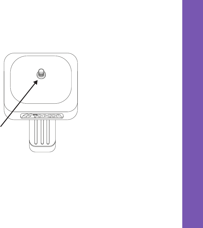
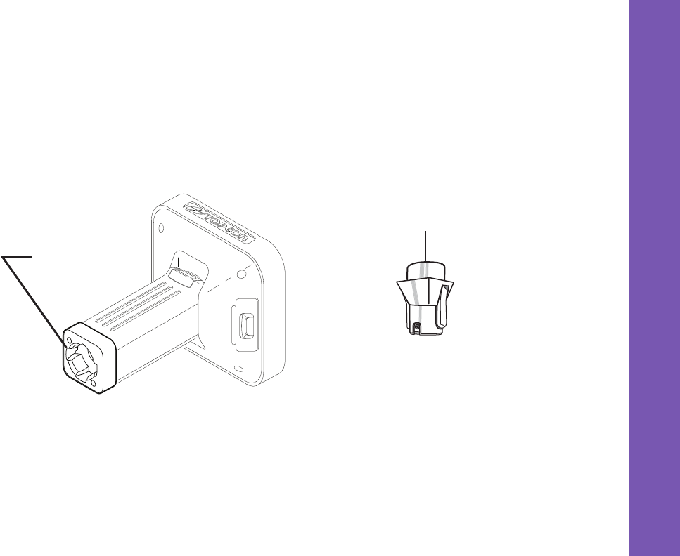
Bottom Connector
The bottom connector (Figure 6) connects the receiver to either a standard 5/8'' thread pole/adapter or the quick
disconnect. The quick disconnect adapter (p/n: 02-850905-01??) connects to the range pole for the receiver to
slip into the top. Using the side clips, the receiver can be quickly connected to/disconnected from the range
pole.
Figure6:GRͲ5QuickConnector
Bottom Connector
for Standard Setups
Quick Disconnect
Adapter
Getting Acquainted
SD/SDHCandSIMCardSlots
17
P/N:7010Ͳ1004
SD/SDHC and SIM Card Slots
TheSD/SDHCandSIMcardslotsarelocatedunderthebatterycompartmentsnearthebaseofthedome.Formore
informationabouttheSD/SDHCcard,see“Memory”onpage 61.FormoreinformationaboutSIMcards,see“SIMCard
Slot”onpage 18.
Figure7:GRͲ5CardSlots
MemoryCard
SlotisHere SIMCardSlot
isHere

Getting Acquainted
SD/SDHCandSIMCardSlots
18
P/N:7010Ͳ1004
SIM Card Slot
TheSIMcardslotislocatedtotherightoftheLEDDisplayPanelinsidethebatterycompartment.Itenablesyoutoinstall
astandardSIMcardintothereceiver.Onceinstalled,theSIMcardprovidesauniqueidentificationforthereceiver’s
GSM/CDMAmoduleandenablesthereceiver’sGSM/CDMAfunctionalitybasedonthesubscribedservices(thereceiver
boardaccessestheGSM/CDMAmodule,whichaccessestheSIMcard).TheSIMcardusuallyremainsinsidethereceiver.
YoucanaccesstheGSM/CDMAmodule,withtheSIMcardinstalled,viaTRUforconfigurationpurposes.ASIMcardcan
bepurchasedfromalocalcellularprovider.
Recommended SIM Cards
TheSIMcardmustsupportCircuitSwitchedDatatocommunicatedirectlybetweenreceivers.TheSIMcardmusthave
GPRSsupporttocommunicateoveraTCP/IPnetwork.
Installing the SIM Card
1. Makesurethereceiveristurnedoff.
2. RemovethedetachablebatterytotherightoftheLEDDisplaypanel.
3. CarefullyinserttheSIMcard,labelͲsideup,intotheSIMcardslotlocatedatthetopofthebatterycompartment.
Oncethereceiveristurnedon,thereceiverboardwilldetecttheSIMcard,anditwillbereadytouseasneeded.
BoththeBaseandRoverreceiversmusthaveaSIMcardinstalled(supportingCircuitSwitchedData)andhave
subscriptionstothesameserviceproviderforpropercommunication.
DisplayPanelOperations
19
P/N:7010Ͳ1004
• • • • • •
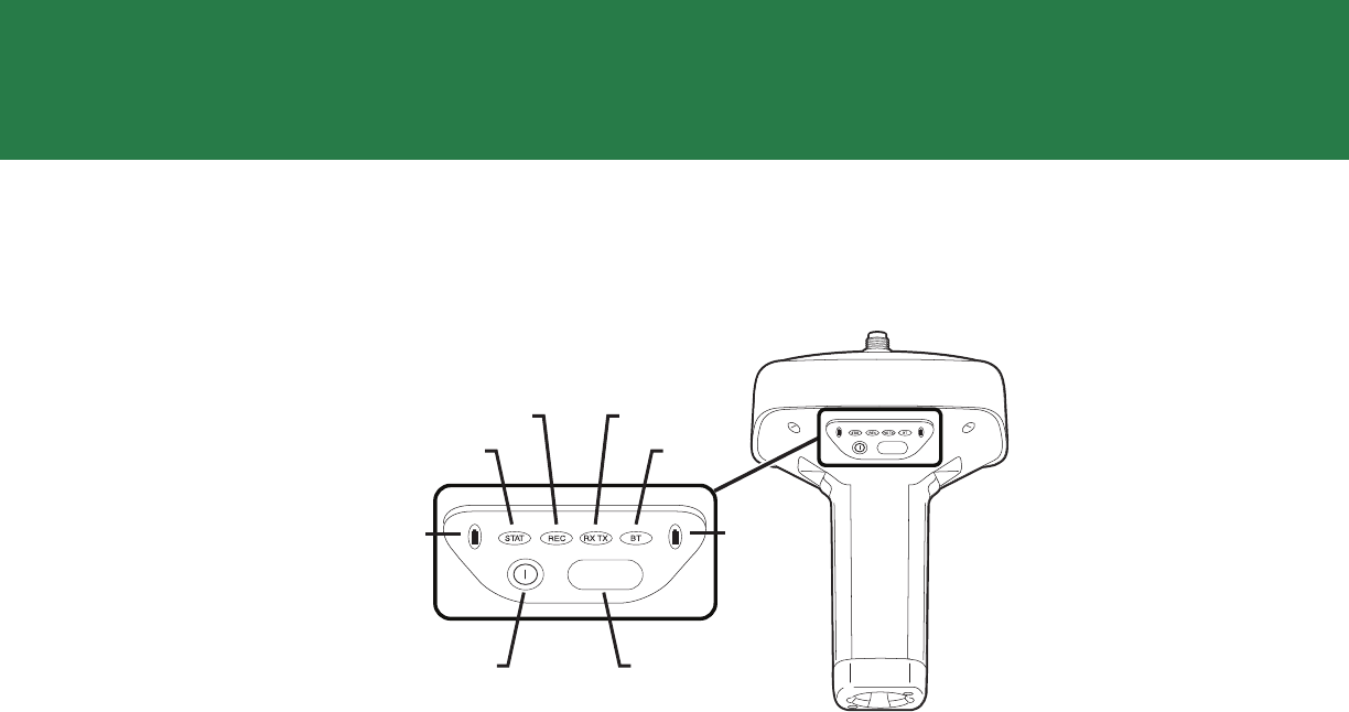
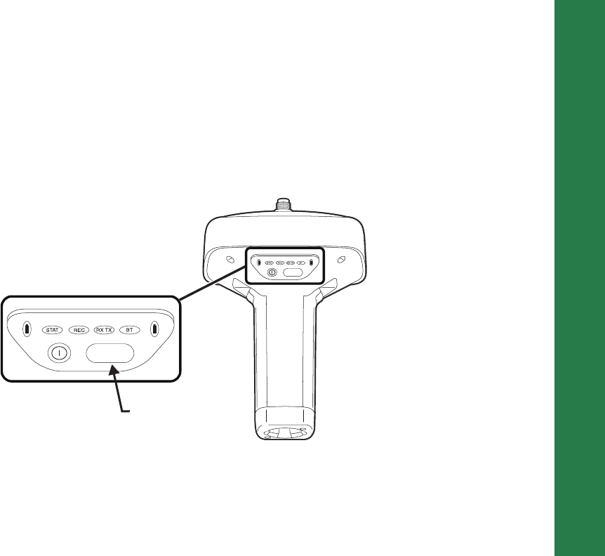
Display Panel Operations
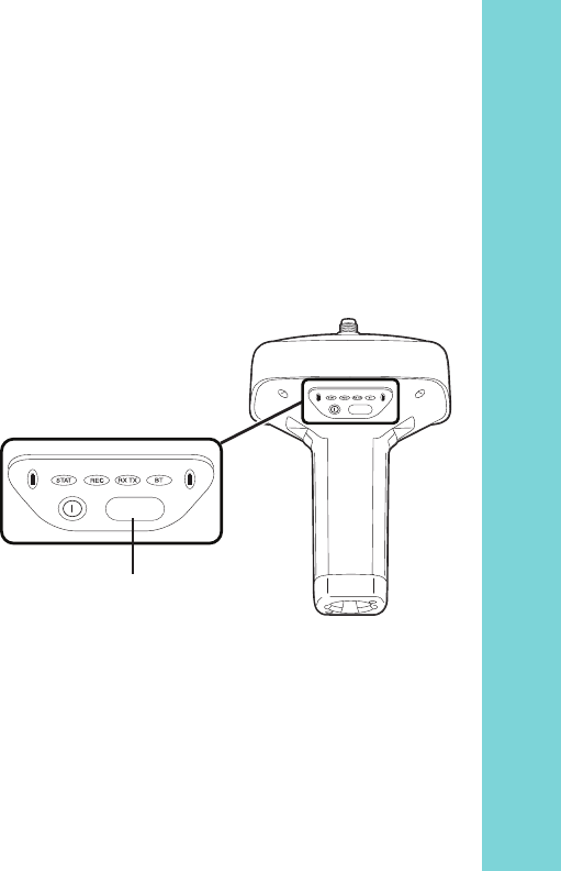
TheLEDdisplaypanel(Figure 8)enablesyoutocontrolreceiverpoweranddatarecording.TheLEDsdisplaythestatusof
thesatellitetracking,recording/memorycapacity,Bluetoothconnections,andbatteries.Thischapterdescribesthedifferent
LEDblinkpatternsandwhattheymean.
Figure8:LEDDisplayPanel
FUNCTION
FUNCTION
Battery
STAT
REC RX TX
BT
Power
Button
FUNCTION
Button
Battery
Display Panel Operations
PowerButton
20
P/N:7010Ͳ1004
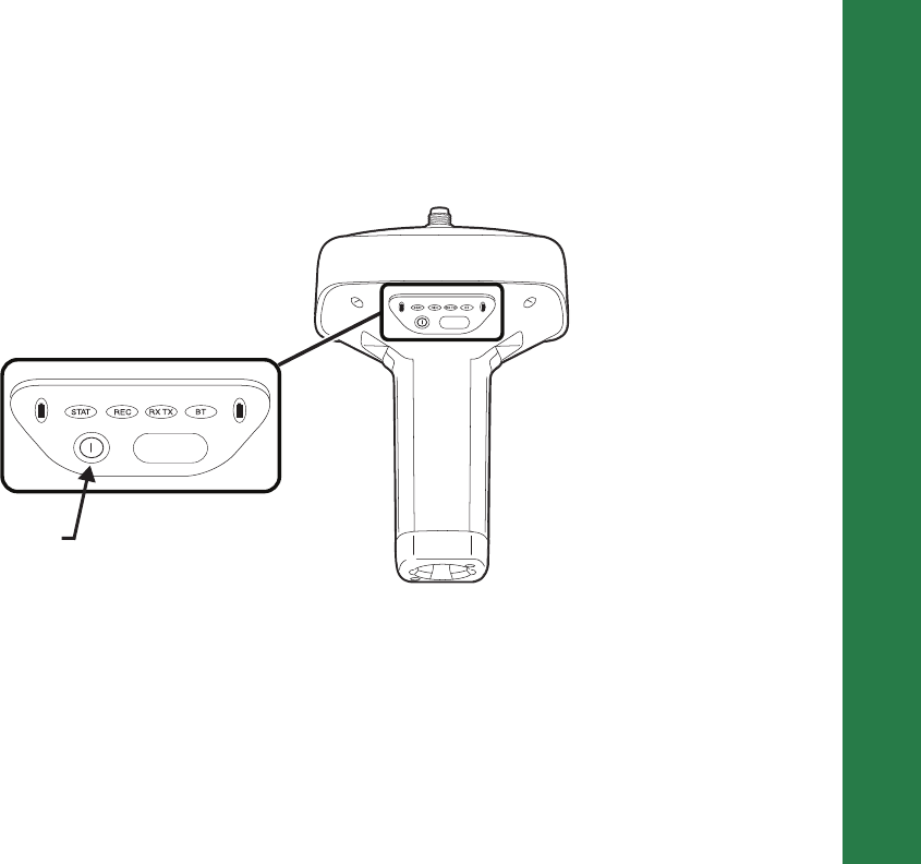
Power Button
Thepowerbuttonturnsthereceiveronandoff.Whenturningthereceiveron,pressthePowerbuttonuntiltheLEDs
brieflyflash.Whenturningoffthereceiver,pressthePowerbuttonuntiltheLEDsgoout.
Figure9:PowerButtonFunctions
FUNCTION
FUNCTION
Power
Button
Press the power
button for about 1
second to turn the
receiver on/off.
Display Panel Operations
FUNCTIONButton/LoggingData
21
P/N:7010Ͳ1004
FUNCTION Button/Logging Data
ThisbuttonswitchesthereceiverbetweeninformationmodesandpostͲprocessingmodes,starts/stopsdatarecording,
andchangesthebaudrateoftheserialportto9600.TheFUNCTIONbuttonenablesyoutoturndatarecordingonoroff.
SeeTable 2tolearnhowtousetheFUNCTIONbutton.
Eachtimedatarecordingisturnedofforon,eitheranewfileopensordataappendstoaparticularfile.
Figure10:FUNCTIONButton
FUNCTION
FUNCTION
FUNCTION
Button
Press the FUNCTION
button for 1–5
seconds to start/stop
data logging.

Display Panel Operations
FUNCTIONButton/LoggingData
22
P/N:7010Ͳ1004
Table2.FUNCTIONButtonOperationsandRECLEDStatus
FUNCTION Key REC LED Status
Whendatarecordingisoff,andtheFUNCTIONkeyis...
Notpressed
Nolight Nodatarecording.
Orangeblink Internalfilesystemtestinprogress.
Red Nofreememory;hardwareproblemwithdatarecording.
NoSDHCcard.
Pressedfor<1
second
IfFUNCTIONkeymodeis“LEDblinkmodeswitch”
Orange Releasetochangeinformationmode.
IfFUNCTIONkeymodeis“Occupationmodeswitch”
Orange Nofunction.
Pressedfor1–5
seconds
IfFUNCTIONkeymodeis“LEDblinkmodeswitch”
Green Releasetostartdatarecording(postͲprocessingoccupation
modeundefined).
IfFUNCTIONkeymodeis“Occupationmodeswitch”
Green Releasetostartrecording(KinematicorStaticpostͲ
processingoccupationmode).

Display Panel Operations
FUNCTIONButton/LoggingData
23
P/N:7010Ͳ1004
Pressedfor5–8
seconds
Red ReleasetoturnserialportAbaudrateto9600bps.
Pressedfor>8
seconds
Nolight Nofunction.
Whendatarecordingison,andtheFUNCTIONkeyis...
Notpressed
Red Nofreememory;hardwareproblemwithdatarecording.
IfFUNCTIONkeymodeis“LEDblinkmodeswitch”
Green Datarecordingstarted(postͲprocessingoccupationmode
undefined).
IfFUNCTIONkeymodeis“Occupationmodeswitch”
Green Datarecordingstarted(KinematicpostͲprocessing
occupationmode).
Orange Datarecordingstarted(StaticpostͲprocessingoccupation
mode).
Table2.FUNCTIONButtonOperationsandRECLEDStatus(Continued)
FUNCTION Key REC LED Status

Display Panel Operations
FUNCTIONButton/LoggingData
24
P/N:7010Ͳ1004
Pressedfor<1
second
IfFUNCTIONkeymodeis“LEDblinkmodeswitch”
Orange Releasetochangeinformationmode.
IfFUNCTIONkeymodeis“Occupationmodeswitch”
Orange ReleasetotogglebetweenStaticandKinematicpostͲ
processingmodes.
Pressedfor1–5
seconds
Nolight Releasetostopdatarecording.
Pressedfor5–8
seconds
Red ReleasetoturnserialportAbaudrateto9600bps.
Pressedfor>8
seconds
Nolight Nofunction(datarecordingstillon).
Table2.FUNCTIONButtonOperationsandRECLEDStatus(Continued)
FUNCTION Key REC LED Status

Display Panel Operations
BatteryLED
25
P/N:7010Ͳ1004
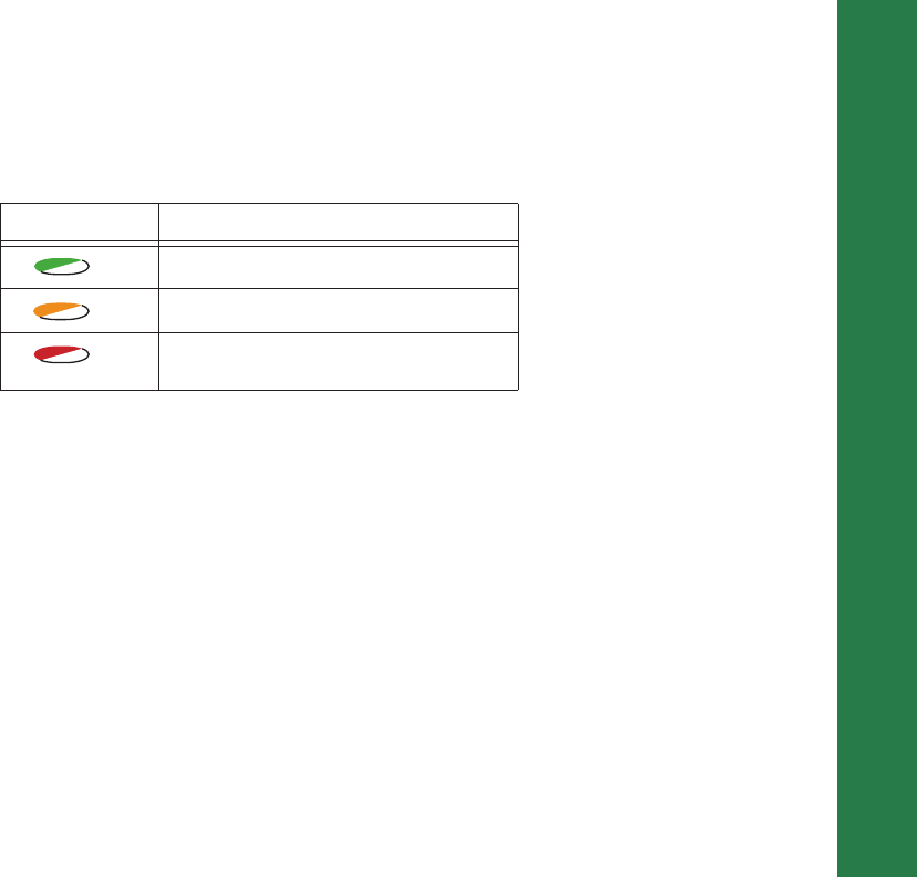
Battery LED
TheBatteryLEDindicatestheremainingchargeofeachdetachablebattery.Whenanexternalpowersourceisutilized,
theLEDturnsgreenandbeginstoblinkifthebatteriesbegintocharge.SeeTable 3formoreinformation.
Table3.BatteryLEDPatterns
LED Color Description
THE RECEIVER IS ON; DETACHABLE BATTERIES IN USE
Thechargeisgreaterthan85percent.
Thechargeisintermediate.
Thechargeislessthan15percent.
THE RECEIVER IS ON; EXTERNAL POWER IN USE
Anexternalpowersourceisinuse,andtheinternalbatteriesarefullycharged.
Theinternalbatteriesareatgreaterthan50%capacity;thebatteriesarebeingcharged.
Theinternalbatteriesareatgreaterthan15%capacity;thebatteriesarebeingcharged.
Theinternalbatteriesareatlessthan15%capacity;thebatteriesarebeingcharged.
THE RECEIVER IS OFF
Thereceiverisconnectedtoanexternalpowersource,andthebatteriesarefullycharged.
Thereceiverisconnectedtoanexternalpowersource,andthebatteriesarebeingcharged.

Display Panel Operations
ReceiverStatusLEDs
26
P/N:7010Ͳ1004
Receiver Status LEDs
TherearefourstatusLEDstoprovideyouinformationaboutthebatterylife,trackedsatellites,memorycapacity,and
Bluetoothwirelessconnectivity.ThissectiondescribesthecolorandbehaviorofeachLED.
RX TX LED
ThisLEDdisplaysthestatusofthemodem.Table 4describestheLEDcolorsandpatternsforthedifferentmodems
availablefortheGRͲ5receiver.
Table4.RXTXLEDs
FH915/Digital II
NoLight ModemisturnedOff
GreenFlashes(greenLED,off,greenLED) Modemisinreceivermode
SolidGreen Aradiolinkhasbeenestablished;modemisreadytoreceivedata
SolidGreenplusyellow(greenLED,greenLED+red
LED) Modemisreceivingdata(Yellowduringactualreception)
SolidRed Modemisintransmittermode
RedFlashes(rapidredLED,off,redLED) Afaultconditionhasbeendetected
RedthenGreen(RedLED,off,greenLED,off) Modemisincommandmode

Display Panel Operations
ReceiverStatusLEDs
27
P/N:7010Ͳ1004
Satel Transceiver
GreenFlashes(greenLED,off,greenLED) Modemisreadytoreceivedata(FCSOFForRXSlave)
GreenwithYellow(greenLED,greenLED+redLED) Modemisreceivingdata(Yellowduringactualreception)
Solidred TxMaster
GreenwithRed(greenLED,redLED) FCSOFF,transmittingdata.(Redduringactualtransmit)
Yellowflashes(green+redLED,off) Receptionisdisabled,eitherbysendingSL+++orusingcommand
Terminal
GSM/HSPA
SolidYellow(RedLED+GreenLED) Modemisinitializing
GreenFlashes Themodemison,registeredonthenetwork,andiswaitingfor
incomingcalls
SolidRed Aconnectionhadbeenestablished
SolidYellow(RedLED+GreenLED)(Satel)Green
Blinks(DUHFIIorSpSp) Themodemisindirectcontrolmode(DaisyChain)
Yellowflashes(greenLED+redLED,off) anerrorhasoccurred(initializationerror,wrongPINcodeetc.)
Table4.RXTXLEDs
Display Panel Operations
ReceiverStatusLEDs
28
P/N:7010Ͳ1004
STAT LED
ThetrackingstatusLEDdisplayshowmanysatellitesthereceiveristracking.
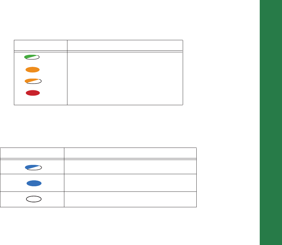
REC LED
TherecordingLEDindicatesifdataisbeingwrittentomemoryanddisplayshowmuchmemorythereceiverhasavailable
forrecording.ForadescriptionoftheRECLEDstatuswhenusingtheFUNCTIONbutton,seeTable 2.
Table 3. Status LED Patterns
LED Color Description
OneblinkpertrackedGPSsatellite.
OneblinkpertrackedGLONASSsatellite.
Oneblinkwhentherearenotracked
satellitesorsolutions.ItisOffotherwise.
Display Panel Operations
ReceiverStatusLEDs
29
P/N:7010Ͳ1004
Bluetooth LED
TheBluetoothLEDdisplaysthestatusoftheBluetoothactivity.Table 5describestheactivity.
Table4.RecordingLEDPatterns
Display Description
GreenBlink:Fileloggingisinprogress.Eachblink
indicatesdataisbeingwrittentotheSDHCcard.
SolidOrange:Thereceiverischangingmodes.
OrangeBlink:Thefilesystemisnotaccessible.
SolidRed:Afaultconditionwiththereceiver(no
morememory,noSDHCcardinserted,a
hardwareproblem,oranimproperOAF.
Table5.BluetoothLEDPatterns
LED Color Description
BlueBlink:Bluetoothisonandwaitingforaconnection.
BlueSolid:AsingleBluetoothconnectionisestablished.
Nolight:Bluetoothisturnedoff.

ManagingPower
30
P/N:7010Ͳ1004
• • • • • •
Managing Power
Thischapterdescribeshowtopowerthereceiver,chargethedetachablebatteries,anduseanexternalpowersource.
Turning On/Off the Receiver
Toturnonthereceiver,pressandholdthepowerbuttonuntiltheLEDsbrieflyflash.Whenthereceiveristurnedon,the
receiver’schannelsinitializeandbegintrackingallvisiblesatellitesatanytimeandlocation.
Toturnoffthereceiver,pressandholdthepowerbuttonformorethanthreeandlessthan10seconds(releasethepower
buttonwhentheBATTLEDblinkssolidred).Thisdelaypreventsthereceiverfrombeingturnedoffbymistake.
Powering the Receiver
Thereceiverispoweredbythedetachable,rechargeablebatteriesoranexternalpowersourceconnectedtothepower
port.Ifanexternalpowersourceisconnected,thereceiverdrawspowerfromitoverthebattery.Whenthedetachable
batteriesaredepleted,andthereisnovalidexternalpowersourceconnectedorifthesourcehasdischargedlowerthan9V,
thereceiverwilldrawitspowerfromtwointernalbatteries(nonͲremovable).Dependingontheusecase,thehoursof
operationprovidedbytheinternalbatteriesvary.
Thereceiverwilldrawasmallamountofpowerfromthebatterieswhenitisturnedoff.Ifthereceiveris
placedinstorageforalongperiod,suchasafewmonths,thebatteriesmaybecomefullydischarged.Youwill
needtouseanexternalpowersupplyorrechargethebatteriesbeforeuse.

Managing Power
PoweringtheReceiver
31
P/N:7010Ͳ1004
Detachable External Batteries
Thereceiverfirstdrawspowerfromonebatteryatatimebeforeswitchingtothesecondbattery.Eachdetachablebattery
providesbetween5and10hoursofoperation,dependingonthereceivermode.Formoreinformation,seeTable 6.
Tocheckthestatusofthedetachablebatteries,viewtheBATTLEDorcheckthestatususingavailableTopcon software.
ChecktheBATTLEDsforbatterystatus:
•
Agreenlightindicatesachargegreaterthan85%.
•
Anorangelightindicatesanintermediatecharge.
•
Aredlightindicatesachargeoflessthan15%.Rechargeorreplacethebatteryassoonaspossible.
Table6.EstimatedOperatingTimesUsingTwoFullyͲchargedBatteries
Common Conditions: Bluetooth = on; 10-12 SV tracked; using the detachable batteries; room temperature
For the GR-5 with FH915+ Modem
Receive only mode 14 hours
250mW transmission mode 12 hoursa
1W transmission mode 10 hoursa
GSM/HSPA in urban areas 13 hours
For the GR-5 with Digital UHFII Modem
Receive only mode 14 hours
0.5W transmission mode 12 hoursa
1W transmission mode 9 hoursa
GSM/HSPA in urban areas 12 hours

Managing Power
PoweringtheReceiver
32
P/N:7010Ͳ1004
Charging the Batteries
Thebatteriesareshippedfromthefactorywithoutpower.Fullychargethebatteriesbeforesurveying.Youcanusethe
powersupplyunitorthebatterychargingcradletochargethebatteries.
For the GR-5 with Satel Modem
Receive only mode 14 hours
0.5W transmission mode 12 hoursa
1W transmission mode 11 hoursa
GSM/HSPA in urban areas 12 hours
Common Conditions: 10–12 SV tracked; using the detachable batteries; room temperature
For the GR-5 with Any Modem
Modem off 20 hours
Common Conditions: 10–12 SV tracked; using the battery shells and AA batteries; room temperature
For the GR-5 with Any Modem
Modem off 2.5 hours
a. At 1 Hz correction rate, charger off.
Table6.EstimatedOperatingTimesUsingTwoFullyͲchargedBatteries

Managing Power
PoweringtheReceiver
33
P/N:7010Ͳ1004
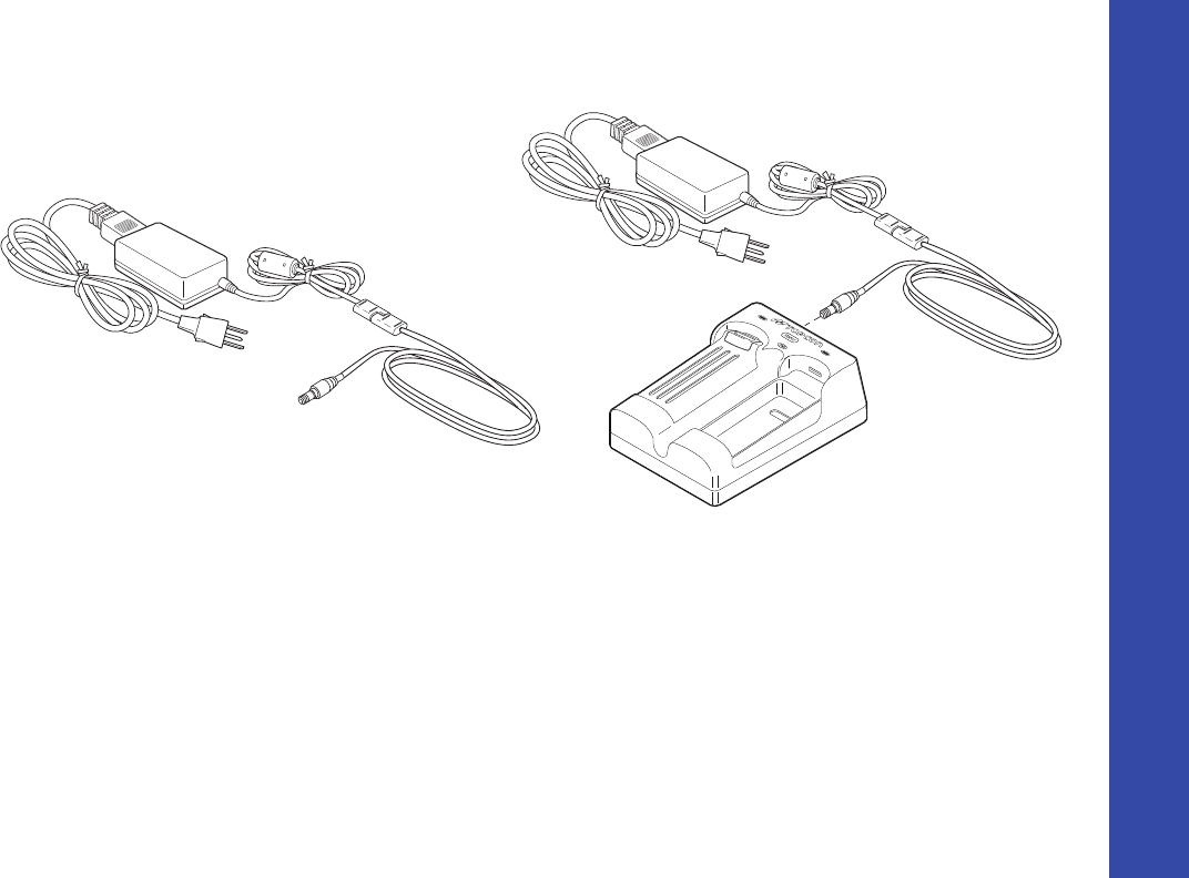
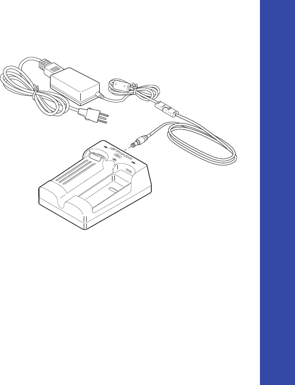
Power Supply Unit
Thepowersupplyunit(p/n22Ͳ034101Ͳ01)chargestheexternalbatterieswhenconnectedtoagroundedoutlet.Thisunit
convertsthealternatingcurrent(AC)normallysuppliedfromanelectricaloutlettoadirectcurrent(DC)usedtocharge
thebatteriesand/orpowerthereceiver.
Youcanconnectthepowersupplyunittothechargingcradleordirectlytothereceiver.See“PowerSupplyUnit”on
page 34.Thepowersupplyhasthefollowingspecifications:
•
inputvoltage–between100and240VAC
•
frequencyofinputpower–between50Hzand60Hz
•
outputvoltage–12VDC@2.5A(30W)
Thepowersupplyunitisdesignedforindooruseonly.Donotuseinadamporawetenvironment.
Donotexposethepowersupplytorainorsnow.Itshouldonlybeusedforchargingthebatteries.
Donotuseasapowersourceduringsurveying.
Managing Power
PoweringtheReceiver
34
P/N:7010Ͳ1004
Figure11:PowerSupplyUnit
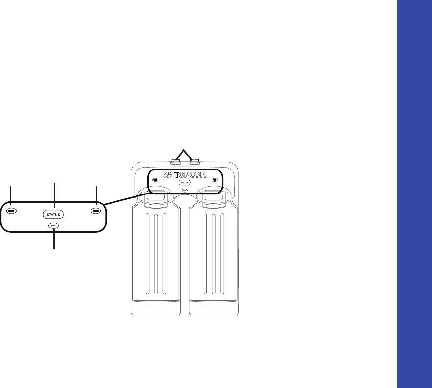
Battery Charging Cradle
Thebatterychargingcradle(Figure 12)connectstoastandardpoweroutletusingthepoweradaptercableandpower
cable/powersupplyunit.
Thechargerhastwoports,onebutton,andthreeLEDs.
•
Thetwoportsconnectthechargertoeitherareceiveroranexternalpowersource.Theportschargeordrainthe
batteriessimultaneously.
To grounded outlet
ToReceiver
ToGroundedOutlet
Managing Power
PoweringtheReceiver
35
P/N:7010Ͳ1004
•
TheSTATUSbuttonactivatesthebatteryLEDs.
Press
STATUS
todisplaytheamountofchargeforthecorrespondingbattery.
•
ThetwobatteryLEDsdisplaythepercentageofchargeintheattachedbattery:
–Agreenlightindicatesachargegreaterthan85%.
–Anorangelightindicatesanintermediatecharge.
–Aredlightindicatesachargeoflessthan15%.Rechargeorreplacethebatteryassoonaspossible.
•
ThepowerLEDlightsupwhenthechargerisconnectedtoanexternalpowersource;suchasanelectricaloutletor
anotherpowersource(12voltbattery).
Figure12:BatteryChargerCradlewithBatteries
Battery
STATUS
Button Battery
Power
Two power in/out ports

Managing Power
PoweringtheReceiver
36
P/N:7010Ͳ1004
Youcanalsoattachthebatterychargertoatripod,abelt,oranRTKpoletoprovideexternalpowertothebasestationor
rover.
BeforeusingtheGRͲ5,fullychargethebatteriesformaximumoperatingtime.
Charging Temperatures
Chargethebatteriesonlyintemperaturesbetween32oF(0oC)and113oF(45oC).
Anoptimalchargingtemperatureisbetween50oF(10oC)and77oF(25oC).Ifpossible,chargethe
batterieswithinthistemperaturerange.
Charging Procedure
Therearetwowaystochargethereceiver’sdetachablebatteries:
•
whiletheyareattachedtothereceiver
•
whiletheyareattachedtothechargingcradle
Ifthebatteriesareattachedtothereceiverortothechargingcradle,inapproximatelysixhoursthebatterieswillbe
simultaneouslyfullycharged.
TheLiͲIonbatteriesusedinthebatterypacksshouldrunatnolessthan80%capacityafter500chargingcycles.Youdo
notneedtodrainthesebatteriesbeforerecharging.
Tochargethebatteriesusingthepowersupplyunit:
0oC
32oF
45oC
113oF
10oC
50oF
25oC
77oF
Managing Power
PoweringtheReceiver
37
P/N:7010Ͳ1004
1. PlugthereceiverͲtoͲSAEpowercableintothe
receiver’spowerinputport.
2. ConnectthereceiverͲtoͲSAEpowercableandthe
powersupplyͲtoͲoutletcabletotheACadapter.
3. PlugthepowersupplyͲtoͲoutletcableintoan
availableoutlet.Thebatteriesarefullycharged
afterapproximately6hours.
Tochargethebatteriesusingthechargingcradle:
1. Removethebatteriesfromthereceiverandinsert
themintothechargingcradle.
2. Connectthepowercabletothepowersupplyunit.
3. ConnecttheSAEconnectorsonthepoweradapter
cableandpowersupplyunit.
4. Connectthepoweradaptercabletooneofthe
portsonthechargingcradle(eitherportwillcharge
both/eitherbattery).
5. Plugthepowersupplytoanavailableoutlet.The
batteriesarefullychargedafterapproximately6hours.
Leaving the Batteries on Charge
Thebatteriescanbesafelyleftinthereceiverorthechargingcradleoncechargingiscomplete.Doingsowillnot
overchargeordamagethebatteries.
To grounded outlet
Managing Power
PoweringtheReceiver
38
P/N:7010Ͳ1004
Thebatteriescanalsobeattached/detachedto/fromthereceiverorchargingcradleatanytimewithoutharmingthe
batteries,thereceiver,orthecradle.Whenreturningthebatteriestothereceiverorcradle,chargingisautomatically
resumed.
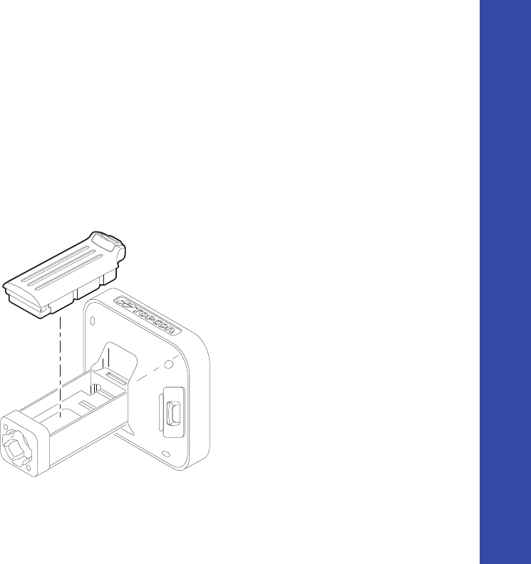
Attaching the Batteries
ToattachthebatteriestotheGRͲ5(Figure 13):
1. Withthebatteryslightlytipped,placethebottomofthebatteryintothebottomofthebatterycompartment.
2. Gentlypushthetopofthebatteryintothebatterycompartmentuntilitsnapsintoplace.Makesurethattheclipat
thetopofthebatterycompletelysnapsintoplace.
Figure13:InsertingtheGRͲ5Batteries
Managing Power
PoweringtheReceiver
39
P/N:7010Ͳ1004
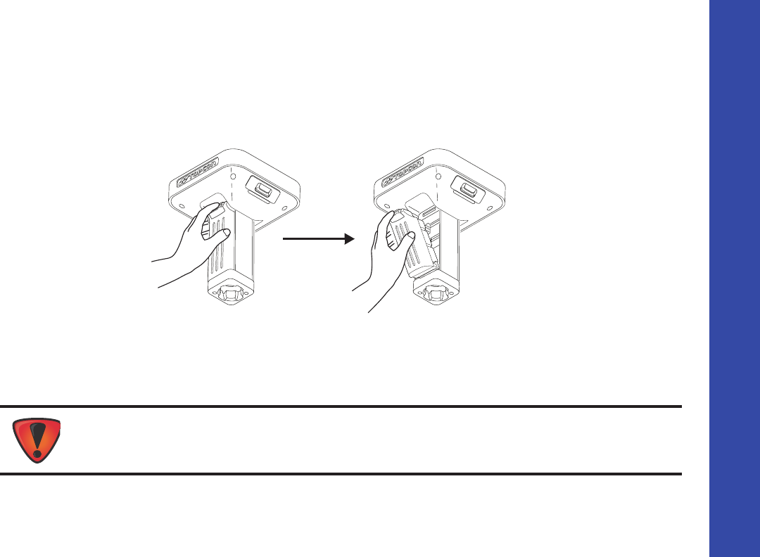
Detaching the Batteries
TodetachthebatteriesfromtheGRͲ5,sothattheycanbechargedorreplaced:
Usingtheclipatthetopofthebattery,gentlypulldownandouttodetachthebatteryfromthereceiver(Figure 14).
Figure14:DetachtheGRͲ5Batteries
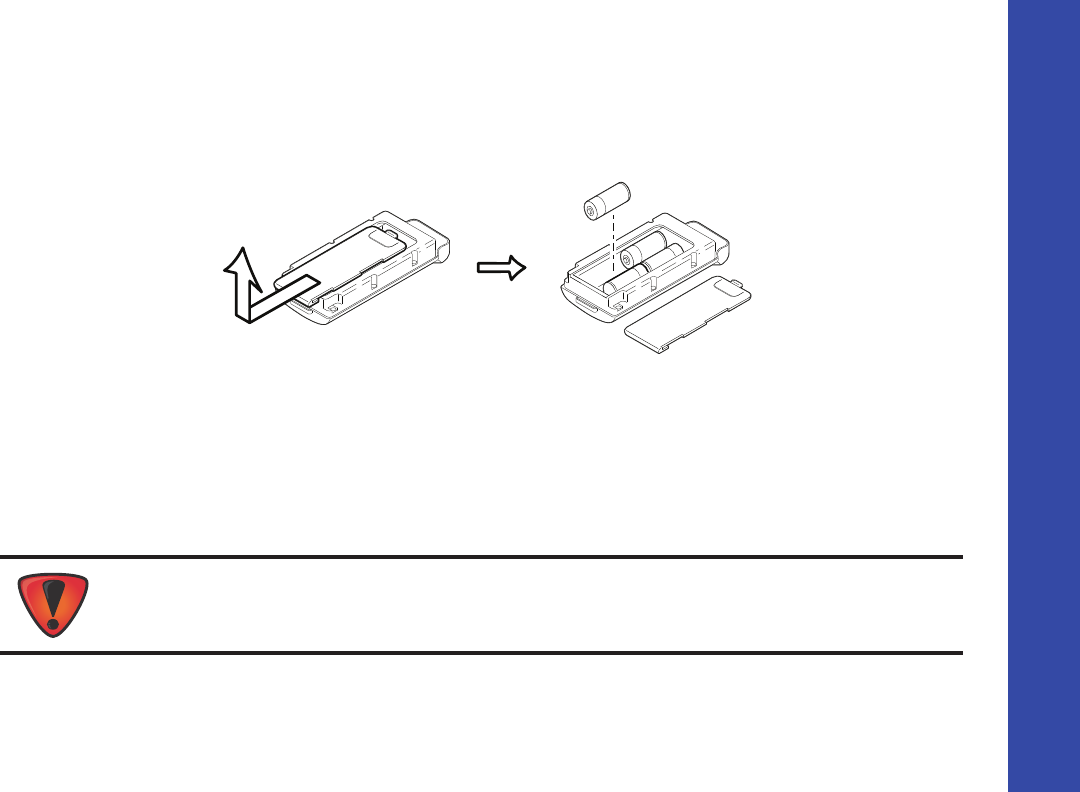
Assembling the AA Battery Shell
ToassembletheAAbatteryshelltotheGRͲ5(Figure 15):
1. SlidethebackcoveroftheAAbatteryshelldownandliftoff.
DonotuserechargeableAAbatteries.
DonotusetheAAbatteryshellwhentheradiomodemisintransmittermode.
Managing Power
PoweringtheReceiver
40
P/N:7010Ͳ1004
2. InsertfourAAbatteriesasshownontheinsideoftheshell(andinFigure 15below).
•
Thebatteriesontheleftlaywiththepositiveendtowardsthebottomoftheshell.
•
Thebatteriesontherightlaywiththepositiveendtowardsthetopoftheshell.
3. Replacethebackcoveroftheshell.
Figure15:RemoveCoverandInsertAABatteries
4. InserttheAAbatteryshellintothebatterycompartmentofthereceiverasshowninFigure 13onpage 4Ͳ38.
Surveying While Charging
TheusercanexecuteanykindofsurveyingwhilechargingtheinternalbatteriesattachedtotheGRͲ5withoutdegradation
ofperformance.
- + - +
+ -
+ -
Whilecharging,makesuretheairtemperatureisbetween+32oF(0oC)and+113oF(+45oC).Thisis
importanttopreventseriousdamagetothebatteries,thereceiverorinjurytopersons.

Managing Power
PoweringtheReceiver
41
P/N:7010Ͳ1004
Changing the Batteries while Surveying
Itissafetochangeadepletedbatterywithafullychargedonewhilesurveying(i.e.,onthefly)withoutturningoffthe
receiver.Beforedoingthis,makesuretheotherbatteryhasenoughchargetopowerthereceiverwhilechangingthe
depletedbattery.Thesurveyingwillnotbedisrupted.Ifneeded,repeatthisprocedureforthesecondbattery.
Using an Auxiliary Power Source
Inadditiontothedetachablebatteries,youcanconnectthereceivertoanexternalpowersource,suchasavehiclebattery
with9to21VDC,tooperatethereceiverandforcontinuoususeofthereceiverifthedetachablebatteriesbecome
discharged.
Toconnectthereceivertoanauxiliarybattery(Figure 16onpage 4Ͳ42):
UsetheODUͲtoͲalligatorclipscable(p/n14Ͳ008097Ͳ01LF)todirectlyconnecttheauxiliarybatteryandthereceiver’s
powerport(withoutSAE).
1. ConnecttheODUͲtoͲalligatorclipscabletoa12Ͳvoltbattery.
2. ConnecttheODUͲtoͲalligatorclipscabletothereceiver’spowerport.
Powerinputgreaterthan21VDCcoulddamagethereceiver.
Whenpoweringthereceiverusingexternalbatteries,setthechargermodetoOff;otherwise,the
detachablebatterieswillalsocharge,causingoperationtimetodecrease.
Managing Power
PoweringtheReceiver
42
P/N:7010Ͳ1004
3. Turnonthereceiver.
Figure16:ConnectanAuxiliaryBatteryandtheReceiver
Asingleexternal12V,2.3A*hbatteryshouldrunthereceiverandmodemforabout9hoursandthereceiverfor13hours.
From receiver to
auxiliary battery
using ODU-to-
alligator clips
cable.
Managing Power
PoweringtheReceiver
43
P/N:7010Ͳ1004
Toconnectthereceivertothechargingcradle(Figure 17):
Thechargingcradlewithextrabatterieshooksontoatripodorbeltforaconvenientpowersupplyforthereceiver.The
partnumberforthereceiverͲtoͲchargercradlecableis14Ͳ008072Ͳ01or14Ͳ008072Ͳ02.
1. ConnectoneendofthecradleͲtoͲreceivercabletothechargingcradle.
2. Connecttheotherendtothepowerportonthereceiver.
Figure17:ConnecttheChargingCradleandReceiver
Connecting the charging
cradle and the receiver using the
cradle-to-receiver charging cable

Managing Power
InsufficientPower
44
P/N:7010Ͳ1004
Insufficient Power
Ifthebatteriesbecomefullydischargedandanexternalpowersupplyisnotconnected,thereceiverwillshutdownand
automaticallysaverecordedfiles.Toavoiddisruptions,checktheBATLEDonthedisplaypanelforthebatterycharge
status.See“BatteryLED”onpage 25formoreinformation.
Ifthereceivershutsdownduetoinsufficientpower,thereceiverandallcommunicationportsbecomedeͲactivated.
Torestorepowertoyourreceiverandturnitbackon,dooneorallofthefollowing:
•
Rechargethebatteries.
•
Makesurethepowercableiscorrectlyconnectedtothereceiver’sport.
a. Alignthekeywayswhenconnectingthepower/serialcabletothereceiverport.
b. Turnthecablelockclockwiseuntilitclickstosecurethecableinplace.
c. Todisconnectthecable,turnthelockcounterͲclockwise,andthengentlyremovethecable.
•
Connectthereceivertoadifferentpowersource.
PowersuppliedtothereceivershouldmatchthespecificationsprovidedbyTopconontheproduct.Failureto
complywiththesespecificationsmaydamagethereceiver.See“Specifications”onpage 78.

ConfiguringtheReceiver
45
P/N:7010Ͳ1004
• • • • • •
Configuring the Receiver
Thesectionsinthischapterdescribereceiveroptions,andhowtoloadanewOptionAuthorizationFile(OAF),updatefirmware,
andperformafactoryreset.Todothis,youwillneedtousetheTopconReceiverUtility(TRU)softwarethatwassuppliedonthe
GRͲ5CD.Forinformationaboutinstallingthesoftware,seetheTopconReceiverUtility(TRU)ReferenceManual.
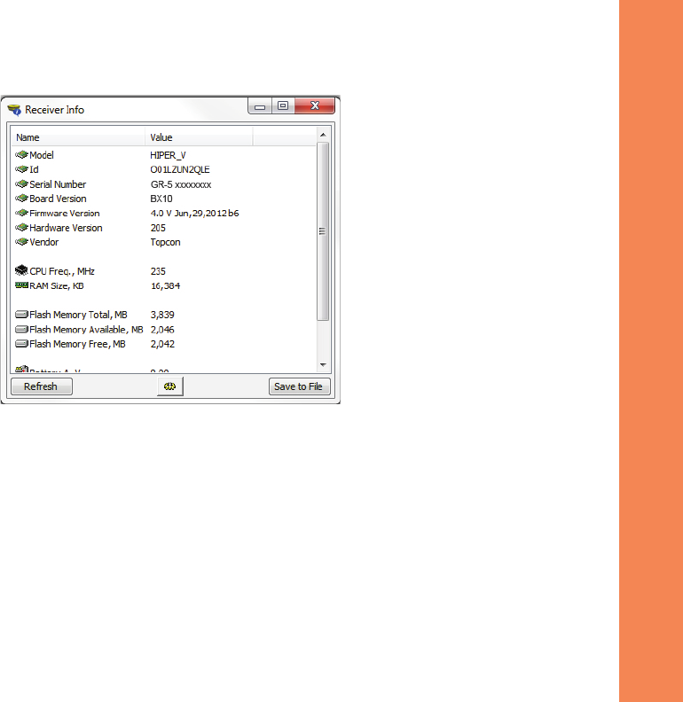
Viewing Receiver Information
IntheTopcon ReceiverUtility(TRU),the
ReceiverInfo
windowdisplaysbasicreceiverinformation,suchashardwareandfirmware
versions,RAMsize,receiverID,serialnumber,etc.
ToopentheReceiverInfowindow:
1. ConnectthereceivertoacomputerandopenTRU.
2. InTRU,connecttothereceiver.
3. ClickDevice
ApplicationMode
ReceiverManaging.
4. ClickDevice
Connect.
5. IntheConnectionParameterswindow,selectthecorrectserialport,andclickConnect.
6. IntheTRUmainwindow,clicktheInformationicon.TheReceiverInfowindow(Figure 6)appears.
Configuring the Receiver
ViewingReceiverInformation
46
P/N:7010Ͳ1004
Figure6:TRU–ReceiverInfo

Configuring the Receiver
LoadingNewFirmware
47
P/N:7010Ͳ1004
Loading New Firmware
Receiverboardfirmwareisreleasedasacompressedfilethatyoudownloadanddecompress.Thisfilecontainsthefollowing
twofiles:
•
ramimage.ldr–theReceiverboardRAMfile
•
main.ldp–theReceiverboardFlashfile
Touploadfirmwarefilestothereceiver:
1. ConnectthereceivertoacomputerusingthePowerandSerialcablereceiveraccessory(p/n:100182Ͳ01).
2. ToconnecttothereceiverinTRU:
a. ClickDevice
ApplicationMode
ReceiverManaging.
b. ClickDevice
Connect.
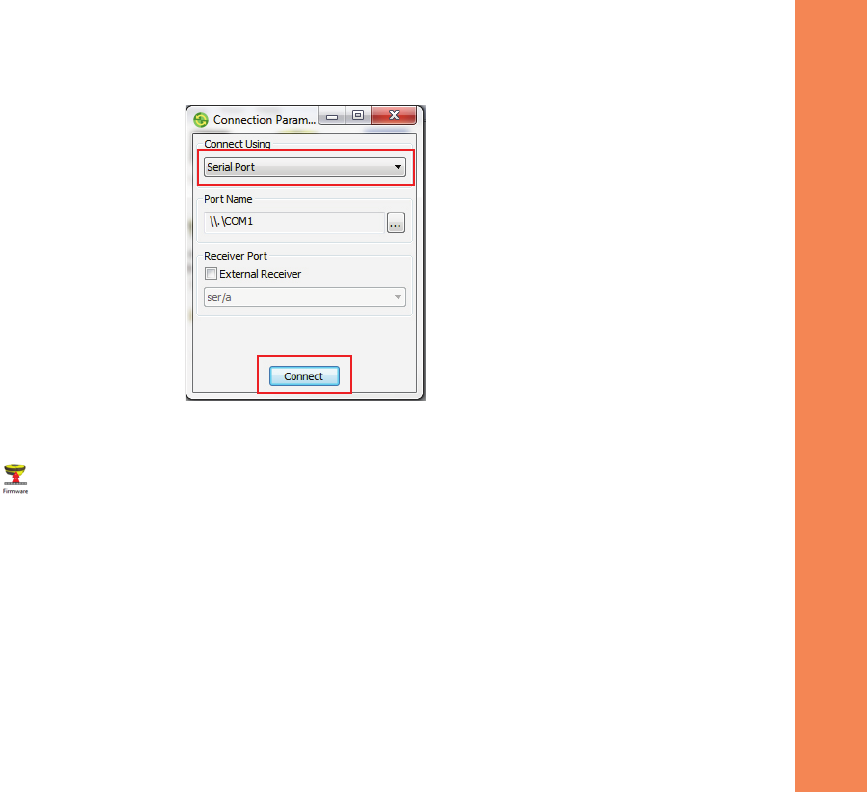
c. IntheConnectionParameterswindow(Figure 7),selectSerialPortandtheportname,andthenclick
Connect.
OnlyusethePowerandSerialcabletouploadfirmwaretothereceiver.UsingaUSBorBluetoothconnection
touploadfirmwarecoulddamagethereceiver.Thenextfirmwarerelease,4.0SR,willsupportUSBor
Bluetoothconnectionsforfirmwareuploads.Seewww.topcontotalcare.comforfirmwareupdates.
Configuring the Receiver
LoadingNewFirmware
48
P/N:7010Ͳ1004
Figure7:ConnectionParametersWindow
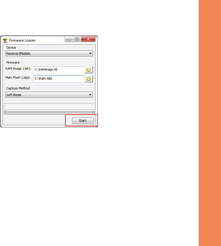
3. ClicktheFirmwareiconintheTRUmainwindow.TheUploadFirmwarewindow(Figure 8)displays.This
windowenablesyoutouploadfirmwarefilestotheconnectedreceiver.
4. MakesureReceiverisselectedintheDevicefield.
5. (Recommended)SelectSoftBreakastheCaptureMethod.
6. Browseforandselectthereceiverboard’sRAMandFlashfiles(Figure 8).
SelectUSBPort
Configuring the Receiver
LoadingNewFirmware
49
P/N:7010Ͳ1004
Figure8:UploadFirmwareWindow
7. ClickStarttouploadtheselectedfiles.
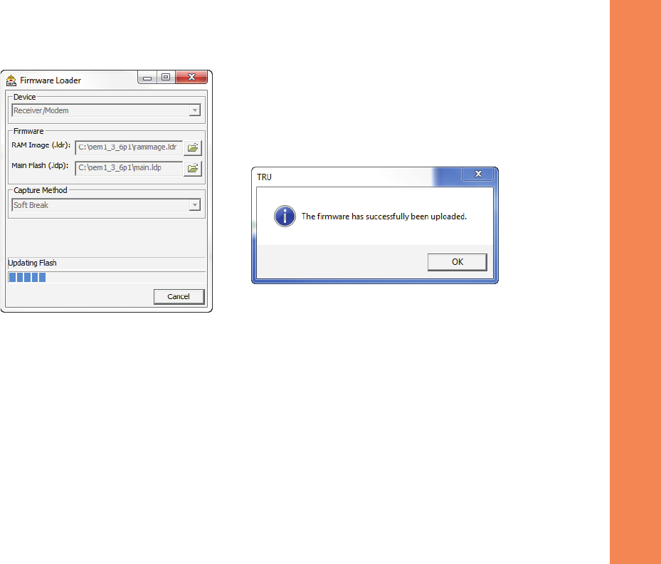
8. ClickOKtocontinueuploadingnewfirmwaretothereceiver(seeFigure 9).
Configuring the Receiver
AbouttheOAF
50
P/N:7010Ͳ1004
Figure9:FinishingFirmwareUpload
About the OAF
TopconissuesanOptionAuthorizationFile(OAF)toenablethespecificoptionsthatyoupurchased.Topcon’sOAFsystemallows
youtocustomizeandconfigurethereceiveraccordingtoyourparticularneeds,thereforepurchasingonlytheoptionsyou
require.
TheGRͲ5receivertypicallyshipswithanOAFasperinitialpurchaseofthereceiverkitconfiguration.Thereareseveralupgrade
optionsavailablewiththereceiverthatcanextendthereceiver’sfunctionalitytobettersuityourjobrequirement.Examplesof
upgradeoptionsarelistedbelow:

Configuring the Receiver
AbouttheOAF
51
P/N:7010Ͳ1004
•
GPS+GLONASSdualfrequencystaticoperation
•
LongLINKbaseandroverRTKoperation
•
NetworkRTKoperation
•
RTKandupdaterateat20Hz
ContactyourTopcondealerorarepresentativeforacompletelistingofavailableoptionsandpricinginformation.
Checking the Receiver’s OAF
TouseTRUtoviewthestatusofthereceiver’soptions:
1. ConnectthereceivertoacomputerandopenTRU.SeetheTopconReceiverUtility(TRU)ReferenceManualfor
moreinformationaboutconnectingthereceivertoacomputer.
2. InTRU,connecttothereceiver.
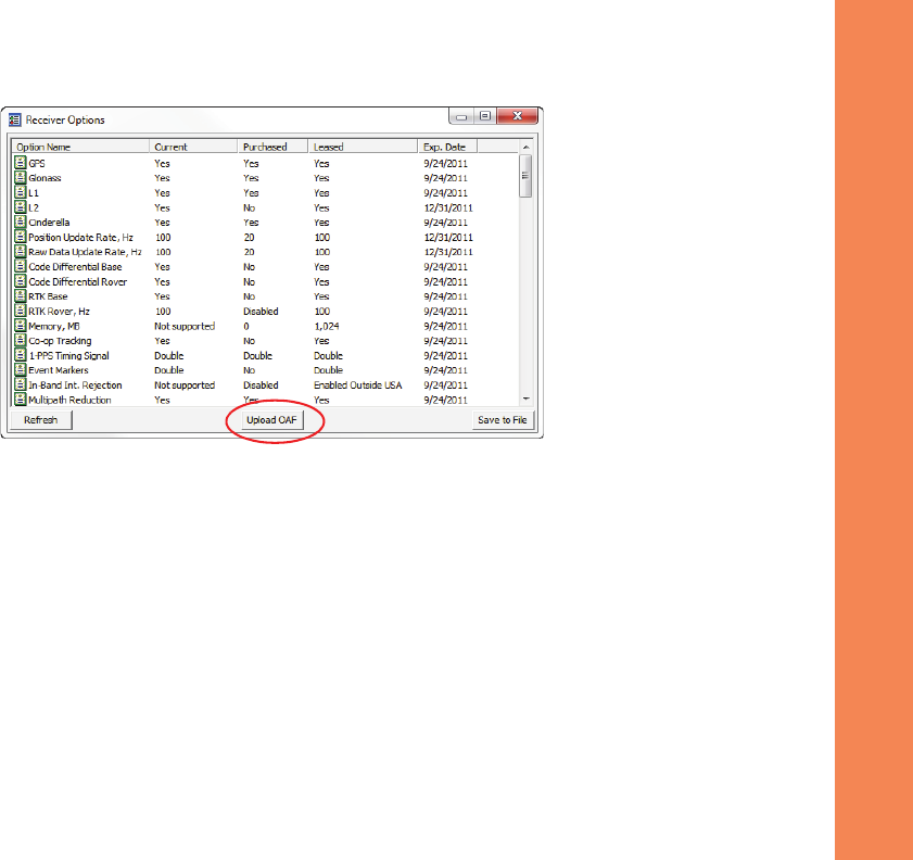
3. ClicktheOptionsiconinthemainwindow.TheReceiverOptionswindow(Figure 10)displays,soyoucanview
thecurrentauthorizationoptionsanduploadnewones.
Configuring the Receiver
AbouttheOAF
52
P/N:7010Ͳ1004
Figure10:ReceiverOptions
Loading an OAF
TopcondealersprovidecustomerswithOAFfiles.ForanyOAFrelatedquestions,eͲmailTopconat
options@topcon.com
and
includethereceiver’sIDandserialnumber.Toobtainthesenumbers,see“ViewingReceiverInformation”onpage 45.
ToloadanewOAF:
1. Followthestepsin“CheckingtheReceiver’sOAF”onpage 51.
2. ClickUploadOAFonthebottomoftheReceiverOptionswindow(seeFigure 10).
Configuring the Receiver
AbouttheOAF
53
P/N:7010Ͳ1004
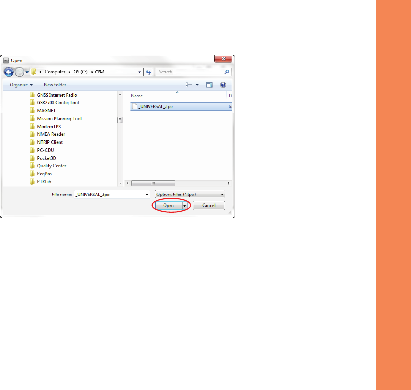
3. NavigatetothelocationofthenewOptionAuthorizationFile(Figure 11).
Figure11:LoadOAF
4. Selecttheappropriatefile,andclickOpen(Figure 11).
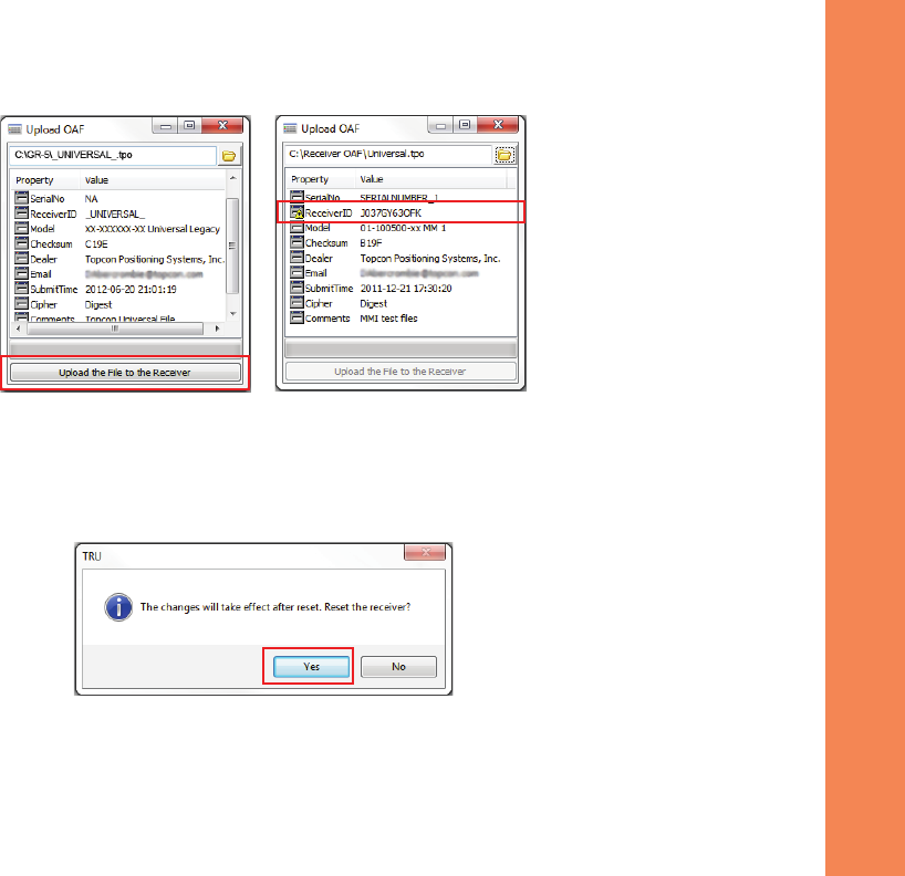
Topcon’s TRUinitiallycheckstoseeiftheselectedfileiscompatiblewiththecurrentlyconnectedreceiver.Ifyou
choseafilenotintendedforthisreceiver,theUploadOAFwindowdisplaysanerroriconnexttotheReceiverIDand
disablestheUploadtheFiletotheReceiverbutton.
Configuring the Receiver
AbouttheOAF
54
P/N:7010Ͳ1004
Figure12:OAFCompatibilityCheck
5. PressUploadtheFiletotheReceiver(Figure 12)tostartloadingthefile.
IfanOAFfileisuploadedtothereceiver,TRUwilloffertoresetthereceivertoputnewauthorizationoptionsinto
operation(Figure 13).
Figure13:ResettheReceiver
6. ClickYes.

Configuring the Receiver
ClearingtheNVRAM
55
P/N:7010Ͳ1004
Clearing the NVRAM
Thereceiver’sNonͲVolatileRandomAccessMemory(NVRAM)holdsdatarequiredforsatellitetracking,suchasephemerisdata
andreceiverposition.TheNVRAMalsokeepsthecurrentreceiver’ssettings,suchasactiveantennainput,elevationmasksand
recordinginterval,andinformationaboutthereceiver’sinternalfilesystem.Clearingthereceiver’sNVRAMrestoresthe
receiver’sfactorydefaultsettings.
AlthoughclearingtheNVRAMisnotrecommendedasacommonpractice,therearetimeswhenitcaneliminatecommunication
ortrackingproblems.
AfterclearingtheNVRAM,thereceiverrequirestimetocollectnewephemeridesandalmanacs(around15minutes).
ClearingtheNVRAMwillnotdeleteanyfilesalreadyrecordedinthereceiver’smemory,andtheNVRAMkeepsinformation
aboutthereceiverfilesystem.
YoucanalsouseTRUtocleartheNVRAM:
1. Connectthereceivertoacomputer,andopenTRU.SeetheTopconReceiverUtility(TRU)ReferenceManualfor
moreinformationaboutconnectingthereceivertoacomputer.
2. InTRU,connecttothereceiver.
Configuring the Receiver
ClearingtheNVRAM
56
P/N:7010Ͳ1004
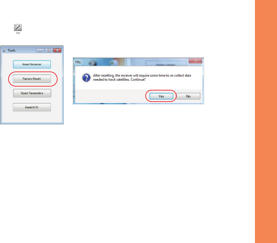
3. ClicktheToolsiconinthemainwindow.
TheToolswindowappears,enablingyoutoresetthereceiverandcleartheNVRAM.
Figure14:ToolsDialogBox
4. ClickFactoryReset,andclickYestocontinue.

FieldSystemSetup
57
P/N:7010Ͳ1004
• • • • • •
Field System Setup
Thischapterdescribesthefieldsetupofyournewreceiver,soitisreadyforuseasaBase,network,RTKRover,orstaticdata
collector.
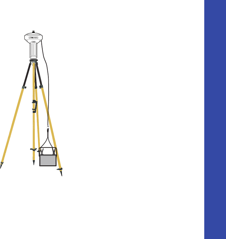
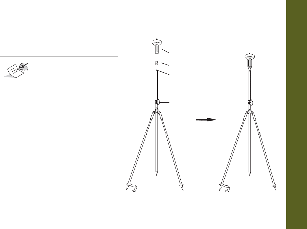
Setting Up the Base Receiver
1. InstallaheavyͲdutytripod(p/n:22Ͳ050501Ͳ01)
overaknownpoint.Youdonotneedauniversal
tribrachandtribrachadapterwhenworkingwith
thistripod.
2. Attachtheantennatothemodemantenna
connector.
3. Levelthetripodandtightenthescrews.
4. Attachanyotheraccessoriesasneeded,suchasa
backͲuppowersupply.
5. Measuretheheightofthereceiverfromthe
groundusingthetapemeasure.See“Measuring
AntennaHeight”onpage 59.
6. ViewtheLEDdisplaypanelforthereceiver’s
currentstatus.Seealso“DisplayPanelOperations”
onpage 19.
GR-5 Receiver
Heavy Duty Tripod
Field System Setup
SettingUptheRoverReceiver
58
P/N:7010Ͳ1004
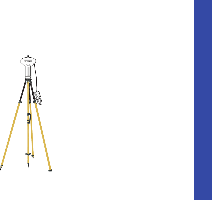
Setting Up the Rover Receiver
1. Ifneeded,attachthequickdisconnecttothe
bipod/rangepole.
2. Attachthereceivertothequickdisconnect.
Makesurethereceiverlocksintoplace.
3. Ifyouarenotusingafixedheightroverpole,
measuretheheightofthereceiverfromthe
ground.See“MeasuringAntennaHeight”on
page 59.
4. Attachtheantennatotheantennaconnector.
5. Pressthepowerbuttontoturnonthe
receiver.Theintegratedwirelessdeviceinthe
receiverturnsonwhenthereceiveris
powered.
6. ViewtheLEDdisplaypanelforthereceiver’s
currentstatus.Seealso“DisplayPanel
Operations”onpage 19.
UseabipodduringpostͲprocess
surveystoensurethe
antenna/receiverdoesnot
moveduringdatalogging.
Lock
GR-5 Recevier
5/8 inch Screw
Quick Disconnect (Optional)

Field System Setup
MeasuringAntennaHeight
59
P/N:7010Ͳ1004
Measuring Antenna Height
Thereceivercalculatesthecoordinatesoftheantenna’sphasecenter.Todeterminethecoordinatesofthestationmarker,
specifythefollowing:
•
Measuredheightoftheantennaabovethestationmarker
•
Methodofmeasuringtheantennaheight
•
Modeloftheantenna/receiverused
Anynecessaryantennaphasecenteradjustments,basedontheantennamodel,isautomaticallyapplied.Thisadjustment,when
combinedwithaccuratelymeasuredheightandmeasurementmethods,allowsforcorrectlycomputedreferencemarker
coordinates.
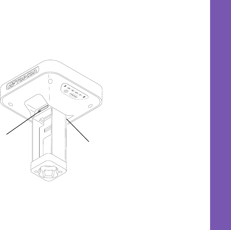
Toaccuratelymeasuretheantennaheight:
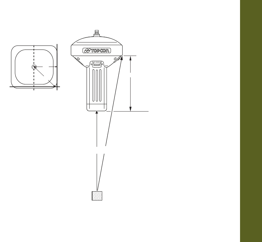
1. Measuretheantennaheightabovethecontrolpointormarker,eithertheslantheightortheverticalheight.
YoumayeithermeasuretheverticalheighttotheAntennaReferencePoint(ARP)locatedatthebottomofthe
receiveratthebaseofthemountingthreads,ormeasuretheslantheighttotheSlantHeightMeasurementMark
(SHMM)onthesideofthereceiver.ForARPandSHMMmarksonthereceiver,seeFigure 18.
2. Recordtheantennaheight,pointsname,andstarttimeinthefieldnotes.
Field System Setup
MeasuringAntennaHeight
60
P/N:7010Ͳ1004
Figure18:AntennaHeightMeasurementPoints
168mm
A
B
A = ARP to edge = 79.0
B = ARP to corner = 97.5
LV LS
SHMM
LV = Vertical Length
LS = Slant Length

CollectingData
61
P/N:7010Ͳ1004
• • • • • •
Collecting Data
Thischapterprovidesgeneralinformationaboutmemory,recordingdata,downloadingdata,andremovingfilestofreeupmemory
space.
Memory
TheGRͲ5isequippedwithanexternalSD/SDHCmemorycardslot.AlthoughyoumayinstallanSD/SDHCcardofany
memorysizeintotheslot,thereceiverrecognizesonlyupto2GBofmemory.TheOptionalAuthorizationFile(OAF)controls
thereceiver’smemorycapacity.Asdataisloggedtothecard,theRECLEDdisplaysthememorycapacitystatus.See“REC
LED”onpage 28formoreinformation.Toaccesstherawdatafilesonthememorycards,see“ManagingFiles”onpage 66.
Collecting Data
Memory
62
P/N:7010Ͳ1004
SD/SDHC Card
TheSDHCcardslotislocatedtotheleftoftheLEDDisplayPanel
insidethebatterycompartmentandconnectsanoptional
SD/SDHCcardtothereceiverboardtoprovidememory.Once
installed,theSD/SDHCcardusuallyremainsinsidethereceiver.
YoucanaccessthedatathatresidesontheSD/SDHCcardviathe
USBorserialport,orBluetoothwirelesstechnology(see
“ManagingFiles”onpage 66).Asecuredigitalcardcanbe
purchasedatalocalcomputersupplystore.
Recommended SD/SDHC Cards
ThefollowingcardsweretestedinthetemperaturerangeofͲ
30°Cto60°C(Ͳ22°Fto140°F):
•
Transcend®UltraIndustrial2GB
•
APRO®Industrial4GB
•
SanDisk®UltraII
•
Swissbit®Industrial2GB
Card Slot
(for SDHC card)
UseonlyindustrialͲgradeSD/SDHCcards.BeforeusinganyotherSD/SDHCcards,consultwithTopcon
CustomerSupportaboutcompatibility.

Collecting Data
Memory
63
P/N:7010Ͳ1004
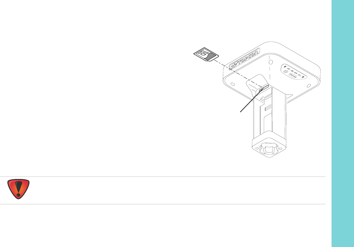
Installing the SD/SDHC Card
1. Makesurethereceiveristurnedoff.
2. RemovethedetachablebatterytotheleftoftheLEDDisplaypanel.
3. CarefullyinserttheSD/SDHCcard,labelͲsidedown,intothecardslotlocatedatthetopofthebattery
compartment.
Oncethereceiveristurnedon,thereceiverboardwilldetecttheSD/SDHCcard,anditwillbereadytouseas
needed.
Initializing the File System
TheGRͲ5supportsaremovableSDHCmemorycardtolograwdatafiles.Thememorycardmustbeinitializedbeforeits
firstuse.InitializingthememorycardwhileinthereceiverensuresthecardisformattedtotheTPSproprietaryfilesystem
(TPFS).Thisfilesystemallowsthereceivertocreate,store,retrieve,delete,andrestorerawdatafiles.
ItisalsoadvisabletoreͲinitializethememorycardperiodically(e.g.,quarterly).Thiserasesanydataonthecard,checks
forbadblocks,andsetsthecardupafresh.
TheusercanuseTRUtoinitializethefilesystem.
AlwaysinitializethefilesystemontheinstalledSD/SDHCcardbeforethefirstuse.TheInitializationprocedure
isdescribedbelow.

Collecting Data
SettingRecordingParameters
64
P/N:7010Ͳ1004
Initializing the File System Using TRU
1. ConnectthereceivertoacomputerandrunTRU.See“ConnectingtheReceiverandaComputer”onpage 16.
2. ClicktheFileExplorericontoopentheFileExplorerscreen.
3. OntheFilestab,pressandholdtheleftmousebuttononthefileline.
4. ClickInitializeFileSystem.
Setting Recording Parameters
TheTopconReceiverUtility(TRU)softwareenablesyoutosetloggingparameters,suchasloggingrateandtypesofmessages,
inwhichtorecorddata.ThissoftwareandtheTRUReferenceManualissuppliedontheGRͲ5CD.SeetheTRUReferenceManual
formoreinformation.TheGRͲ5iscompatiblewithanyTopconfieldsoftwareforconfigurationandrecordingrawdata.
Logging Rates
Theamountofmemoryusedtologdatadependsontheloggingrate.Formoreinformationaboutsettingloggingrate
parameters,seetheTRUReferenceManual.
Initializingthefilesystemofaconnectedreceiverwilleraseallofthereceiver’sdatafiles.Awarningmessage
willappeartoconfirmtheoperation.
Collecting Data
RecordingData
65
P/N:7010Ͳ1004
Recording Data
YoucanlograwGNSSdatatothereceiver’sSD/SDHCcardandusetheTopcon ReceiverUtility(TRU)orMAGNETOffice™
softwaretodownloadthefilestoacomputer.
Tostartorstoprecordingdata,usetheLEDdisplaypanelorTRU:
1. PressthePowerbuttontoturnonthereceiver.
2. WaitfortheSTATLEDtoindicatesatellitesarebeing
tracked.TheSTATLEDblinksgreenforGPSsatellitesand
amberforGLONASSsatellites. Ashortredblinkindicates
thereceiverhasnotsolvedaposition.Fiveormore
satellitesprovideoptimalpositioning.
3. Tobeginrecording,pressandholdtheFUNCTIONbutton,
andthenreleaseit(between1and5seconds)whenthe
REC(Recording)LEDturnsgreen.
4. MakesuretheREClightblinksgreen.Thisindicatesthata
filehasopenedanddatacollectionhasstarted.TheREC
LEDblinkseachtimedataissavedtotheSD/SDHC
memorycard.IftheREClightblinksred,thereceiverhas:
•
ahardwareproblem
•
noSD/SDHCcardinstalled
•
notenoughspaceonthememorycard???
•
animproperOAF
(See“AbouttheOAF”onpage 50)
5. YoucanalsoselectFileExplorer
Logs
StartinTRUtobeginrecordingdata.
FUNCTION
FUNCTION
FUNCTION
Button
Press the FUNCTION
button for 1–5
seconds to start/stop
data logging.

Collecting Data
ManagingFiles
66
P/N:7010Ͳ1004
6. Whenyouhavefinishedrecording,pressandholdtheFUNCTIONbuttonuntiltheRECLEDturnsdark.Youcanalso
selectFileExplorer
Logs
StopinTRUtoenddatarecording.
7. Toturnoffthereceiver,pressandholdthePowerbuttonuntilallLEDsturndark.
Managing Files
RawdataisrecordedastimeͲtaggedmeasurementsinasinglerawdatafile.Eachfileisrecordedtothereceiver’smemory,and
automaticallygivenanameanda*.tpsfileextension.Youcanthentransferafileofcollecteddatacantoacomputerwithfile
managingsoftware,suchastheTo pconReceiverUtility(TRU),whichissuppliedontheGPS+CD.Theseprogramsallowyouto
useanautomaticnamingfeature,enterfilenames,anddeletefilesasnecessary.Formoreinformation,seetheTRUReference
ManualsuppliedontheGRͲ5CD.
Downloading and Deleting Files
Aftercompletingasurvey,downloaddatafilestoacomputeroracontrollerforstorage,postͲprocessing,orbackup.The
SD/SDHCcardsholdafiniteamountoffiles,soyouwillwanttodeletefilestoincreasememorycapacity.
Whenthememoryisfull,thereceiverstopsloggingdata,andtheRECLEDturnsdark/off,indicatinganerrorcondition.Existing
dataisnotoverwritten.
Therearetwooptionsfordeletingrawdatafilesfromthereceiver:
YoucanalsologdatausingMAGNETFieldsoftware.

Collecting Data
ManagingFiles
67
P/N:7010Ͳ1004
•
DeleteallofthefilesusingtheLEDdisplaypanel(i.e.holdthepowerbuttonfor15to20seconds).
Thiserasesallofthe
filesontheSD/SDHCcard
.
•
UseaUSB,serial,orBluetoothconnectiontodownloadthefilestoacomputer.InTRU,youcanselectthefilesyouwant
todeletefromthereceiver.SeetheTRUReferenceManualformoreinformation.
Onceaconnectionisestablished,youcandownloadallorsomefilestoacomputerorcontrollerandthenusetheFileExplorer
featureinTopcon ReceiverUtility(TRU)tomanagetherawdatafiles.FormoreinformationaboutusingTRUtodownloador
deletefiles,seetheTopconReceiverUtility(TRU)ReferenceManualincludedontheGRͲ5CD.

Troubleshooting
68
P/N:7010Ͳ1004
• • • • • •
Troubleshooting
Thischapterwillhelpyoudiagnoseandsolvesomecommonproblemsthatmayoccurwiththereceiver.
Check This First!
BeforecontactingyourlocaldealerorTopconTechnicalSupport,checkthefollowing:
•
Checkallexternalreceiverconnectionscarefullytoensurecorrectandsecureconnections.Doublecheckforwornor
defectivecables.
•
Checkthereceiver’sinternalbatteriesforafullcharge.
•
Checkthepowersourceforincorrectlyconnectedcables,andensurethepowersourceisvalid.See“Specifications”on
page 78forexternalpowerrequirements.
•
Checkthesoftware.Makesurethemostcurrentsoftwareversionisdownloadedontothecomputerandthemostcurrent
firmwareisloadedintothereceiver.ChecktheTopconwebsiteforthelatestupdates.
•
CheckTopconTechnicalSupport(www.topconsupport.com)orTo pconTotalCare(www.topcontotalcare.com)forthe
latestupdates.
Then,trythefollowing:
•
PoweronandoffthereceiverbypressingthePowerbuttonorbyusingTRU(
Tools
Resetreceiver
).
Donotattempttorepairequipmentyourself.Doingsowillvoidthewarrantyandmaydamagethehardware.

Troubleshooting
PoweringProblems
69
P/N:7010Ͳ1004
•
RestoredefaultsettingsbypressingthePowerbuttonfor10to15secondsorusingTRU(
Tools
ClearNVRAM)
.
This
restoresthereceiver’sparameterstothefactorydefaultsettingsanderasesthealmanacandephemerisfiles.This
actiondoesnotdeletedatafilesfromthereceivermemory.
•
EraseallfilesbypressingthePowerbuttonfor15to20secondsorbyusing
FileExplorer
DeleteAllFiles
inTRU.This
willdeleteallfilesstoredinthereceiver’snonͲremovablememorycard.
Iftheproblempersists,seethefollowingsectionsforothersolutions.
Powering Problems
Thefollowingaresomeofthemostcommonlyencounteredpowerproblems.
Thereceiverdoesnotpowerup
•
Thebatterymaybedischarged.
–Chargethebatteryovernight.See“ChargingtheBatteries”onpage 32.
•
Ifyouareusinganexternalpowersource,thecablemaybedisconnectedordamaged.
–Makesurethecableissecurelyconnectedandundamaged.
•
Thereceivermayhaveadefectivechargerordefectivebattery.
–If,afterchangingthebatteryorconnectinganexternalpowersource,thereceiverstilldoesnotpowerup,
contactyourlocaldealerorTopconTechni calSupportforadvice.

Troubleshooting
ReceiverProblems
70
P/N:7010Ͳ1004
Receiver Problems
Thefollowingaresomeofthemostcommonlyencounteredreceiverproblems.
Thereceivercannotestablishaconnectiontoacomputerorexternalcontroller
Cablespecificproblems:
•
Thecableisnotproperlypluggedin.
–Unplugthecable,thensecurelyandproperlyreconnectittothereceiver.
•
Thecableisdamaged.
–Useanundamagedcable.Contactadealertoreplacethecable.
•
TheUSBdriverisnotinstalled.
–IfyouareusingaUSBcableconnection,makesuretheUSBdriver,includedontheGPS+SoftwareCD,is
installedonthecomputer.YoucanalsodownloadthedriverfromtheTopconsupportWebsiteat
www.topcontotalcare.com.
Genericproblems:
•
ThereceiverportusedforconnectionisnotinCommandmode.
a. ConnectthereceivertoacomputerandopenTRU(see“Connection”intheTopconReceiverUtility(TRU)
ReferenceManual).
b. ClickReceiverSettings
Ports.
c. ChangetheInputModefortheportusedforconnectiontocmd.

Troubleshooting
ReceiverProblems
71
P/N:7010Ͳ1004
Thereceiverdoesnotlockontosatellitesforalongperiodoftime
•
Thecorrespondingreceiveroptionsmaybedisabledorexpired(L1/L2,GPS/GLONASSmustbeontotracksatellites).
–OrderanewOAFwiththedesiredoptionsactivatedtoenableorextendvalidityofthecorrespondingreceiver
options.ContactadealerorvisittheTopconwebsitefordetails.
–Refertothe“ReceiverManaging”chapteroftheTopconReceiverUtility(TRU)ReferenceManualforadetailed
descriptionofoptions.
Thereceivertrackstoofewsatellites
•
Thesurveyisconductednearobstructions(treecanopy,tallbuildings,andsoforth).
–MakesuretheMultipathReductionboxeshavebeenenabled.
a. ConnectthereceivertoacomputerandopenTRU(see“Connection”intheTopconReceiverUtility(TRU)
ReferenceManual).
b. InTRU,connecttothereceiver.
c. OntheTRUmainwindow,chooseReceiverSettings
Tracking
Advtab.MakesuretheC/Acode
multipathreductioncheckboxisselected.
•
Movetoanareafreeofobstructions,ifapplicable.
ThereceivercannotobtainCodeDifferentialand/orRTKsolutions
•
IncorrectBasecoordinatesentered.
–SpecifythecorrectcoordinatesfortheBasestationusingTRUoranothersuitablefielddatacollectionsoftware.
•
Therecouldbesomeobstructiontotheconnection.
–ClearallpossibleobstructionsorrelocatetheBasesothereisa“lineͲofͲsight”pathtotheRover.
•
Thecorrespondingreceiveroptionsmaybedisabledorexpired.

Troubleshooting
ReceiverProblems
72
P/N:7010Ͳ1004
–OrderanewOAFwiththerequiredoptionsactivatedtoenableorextendvalidityofthecorrespondingreceiver
options.
–RefertotheTopconReceiverUtility(TRU)ReferenceManualforadetaileddescriptionofoptions.
•
Therearenotenoughcommonsatellites.Inordertoobtainafixedsolution,theBaseandRovershouldtrackatleast
fivecommonsatellites.
–ChecktheelevationmasksoftheRoverandBasereceivers;theyshouldbethesame.Todothis,ontheTRU
mainwindow,chooseReceiverSettings
Tracking
Obs.
–Verifythereisaclearviewoftheskytoallowsufficientsatellitetracking.
•
AdiscrepancyexistsbetweenthedifferentialstandardsusedattheBaseandRoverreceivers.
–EnsuretheBaseandRoverreceiversusethesamecorrectionsinput/outputformat:
a. ConnectthereceivertoacomputerandopenTRU(see“Connection”intheTopconReceiverUtility(TRU)
ReferenceManual).
b. InTRU,connecttothereceiver.
c. OntheTRUmainwindow,chooseReceiverSettings
Ports.
d. DoubleͲclickontheporttobeconfiguredandmakesuretheinputmodeoftheRovermatchestheformat
oftheBaseoutputmode(i.e.RTCM3).
•
Poorsatellitegeometry(PDOP/GDOPvaluesaretoohigh).
–Conductthesurveywheresatellitevisibilityisbetter(lowPDOPvalue).
–Ensuretheelevationmaskislessthan15degrees.
–IncreasethePDOPthreshold.Todothis,ontheTRUmainwindow,chooseReceiverSettings
Tracking
Obs.
•
Theelevationmaskisabove15degrees.
–Lowertheelevationmask.To dothis,ontheTRUmainwindow,chooseReceiverSettings
Tracking
Obs.
–Verifythereisaclearviewoftheskytoallowsufficientsatellitetracking.

Troubleshooting
ReceiverProblems
73
P/N:7010Ͳ1004
•
Themodembatteryislow.
•
Thespecifiedbaudrateisincompatiblewiththebaudratesthemodemsupports.Thebaudrateistherateatwhichthe
receivertransmitsdifferentialmessagestothemodemandviceversa.
–Changethemodem’sbaudrate.
•
TheBaseandRovermodemsusedifferentradiolinkparameters.
–ConfiguretheBaseandRoverradiomodemsaccordingtotheprocedureslistedintheTRUReferenceManual.
•
ThedistancebetweentheBaseandRoveristoofar.
–ClosethedistancebetweentheBaseandRover.
–Userepeaterstoincreaseradiocoverage.
•
Theremaybeasourceofradiointerferencethatdisruptsradiocommunications.
–ChangetheRFchannel(ifpossible).
–Removingthesourceofthejammingsignalorrelocatetheradioantennas(ifpossible).
Thereceiverdoesnotstartloggingdata
•
TheSD/SDHCcardisnotproperlyinserted.
•
Thereceiver’smemoryisdisabledorexpired.
–Makesurethememoryoptionisenabled.Fordetails,seetheTopconReceiverUtility(TRU)ReferenceManual.
•
Thememorycarddoesnothavefreespace.
–Downloadand/ordeletedatafilestofreeupspacefornewfiles.See“DownloadingandDeletingFiles”on
page 66.
–Thefilesystemisnotinitialized.InitializetheFileSystemontheSDcardusingTRU.Todothis,ontheTRUmain
window,chooseFileExplorer
InitializeFileSystem.

Troubleshooting
BluetoothProblems
74
P/N:7010Ͳ1004
Bluetooth Problems
Thefollowingaresomeofthemostcommonlyencounterederrormessagesandotherproblems.
TRUerrormessage:Can’tfindreceiver
•
Thereceiveristurnedoff.
–Ensurethereceiverhaspowerandisturnedon.
•
Bluetoothisnotturnedon;theBTLEDisoff.
–ResetthereceivertothefactorydefaultsettingsbypressingthePowerbuttonfor10to15seconds.
–YoucanalsoturnonpowertoBluetoothusingTRU.Todothis,ontheTRUmainwindow,chooseReceiver
Settings
Bluetooth.
•
Thereisinterference.
–Movethereceiver,controller,orcomputertoanunobstructedlocation.
•
Thereceiveristoofaraway.
–Movethedevicesclosertogether.
•
ThereceiverisalreadyconnectedviaBluetoothtoanotherdevice.
–Disconnectthereceiverfromtheothercontrollerorcomputer.
•
ThereceiverportusedforconnectionisnotinCommandmode.
a. ConnectthereceivertoacomputerandopenTRU(see“Connection”intheTopconReceiverUtility(TRU)
ReferenceManual).
b. ClickConfiguration
Receiver
Ports.

Troubleshooting
BluetoothProblems
75
P/N:7010Ͳ1004
c. ChangetheInputModefortheBluetoothserialportusedforconnectiontocmd.
TRUerrormessage:OpenCOM#portfailed:Accessisdenied
•
Anotherapplicationusesthecomputerportdedicatedforconnection.
–Closetheapplication,andthenreͲconnect.
–Connectthereceiverviaanother,unusedcomputerport.
Aftersearchingforavailabledevices,nonearediscovered
•
Thereceiverisnotreceivingpower.
–Checkthatthereceiverisgettingpowerandisturnedon.
–Checkthatthepowercableiscorrectlyattachedtotheportifoneisbeingused.
–Unplugthecable,thensecurelyandproperlyreconnectittothereceiver.
–Ifthepowercableisdamaged,contactaDealertopurchaseanewcable.
Canseetheiconforthereceiver’sBluetoothmoduleonthecomputerscreen,butcannotconnecttoit
•
Devicesecuritysettingsprobablydiffer.
–MakesuretheBluetoothenableddevicesusethesamesecuritysettings.
•
Bluetoothmodulesettingsmayhavechanged.
Thisisthemostcommoncauseforthiserrormessage.UseTRUtodoublecheckthesettingsforthe
connectionport.

Troubleshooting
TRUProblems
76
P/N:7010Ͳ1004
a. IfthesettingsarechangedfortheBluetoothmodule,removeitfromthelistofdiscoveredBluetooth
devicesusingtheBluetoothmanagerprogram(suppliedwiththedeviceusedtomanagethereceiver).
b. Repeatthesearch.
TRU Problems
ThefollowingisthemostcommonlyencounteredTRUproblem.
TRUcannotconnecttothereceiver
•
Thereceiveristurnedoff.
–Ensurethereceiverhaspowerandisturnedon.
•
Ifusingacable,thecable’sconnectorsareimproperlyattached.
–Checkthatthecableconnectorisattachedtothecorrectserialport.
–Unplugthecable,thensecurelyandproperlyreconnectittothereceiver.
•
Ifusingacable,thecableisdamaged.
–Useanundamagedcable.
–Contactadealertopurchaseanewcable.
•
IfusingBluetoothwirelesstechnology,theincorrectportisselected.
–UseacomputerorreceiverthathasBluetoothwirelesstechnologyenabled/installed.
–Makesurethecomputerandreceiverusethecorrectportsforcommunication.FortheGRͲ5receiver,thisis
BluetoothserialportA(btsp\a).

Troubleshooting
CleaningandStoringtheReceiver
77
P/N:7010Ͳ1004
Cleaning and Storing the Receiver
•
Useacleanclothmoistenedwithneutraldetergentorwater.
•
Neveruseanabrasivecleaner,ether,thinnerbenzene,orothersolvents.
•
Alwaysmakesurethereceiveriscompletelydrybeforestoringit.Dryanymoisturewithasoft,cleancloth.
Getting Customer Support
Ifthetroubleshootinghintsandtipsinthisoperator’smanualfailtoremedytheproblem,contactTopconCustomerSupport.
Forcontactinformation,see“GettingTechnicalSupport”onpage 6.

Specifications
78
P/N:7010Ͳ1004
• • • • • •
Specifications
TheGRͲ5isaVanguardtechnologyͲbasedGNSSreceiverfeaturing226channelsandLongLINKwirelesstechnologyforsmalljob
siteoperationsandcableͲfreenetworksolutions.Thischapterprovidesspecificationsforthereceiveranditsinternalcomponents.
General Details
Table 7liststhereceiver’sgeneralspecifications.
Table7.GeneralReceiverSpecifications
Physical
Enclosure Magnesium,IPX6extrusion,rainproof
Color TopconYellowandGray(bumper)
Dimensions(mm) 158.1(w)x253(h)x158.1(d)
Weight1.88kgwithbatteries,1.44kgwithoutbatteries
Antenna Internal
Battery Twoexternal,detachable
Controller External

Specifications
GeneralDetails
79
P/N:7010Ͳ1004
Mounting 5/8Ͳ11,quickdisconnect
Seals Silicon(moldingincolor)
Keys Twokeys:
•Power–On/Off
• Function–start/stopdatalogging;switchinformationmode
LEDs SixLEDs:
•STAT–satelliteandreceiverstatus
•REC–recordanddatastatus
•RXTX–modemstatus
•BT–Bluetoothwirelesstechnologyconnectionstatus
•BATT(x2)–batterystatus
Environment
Operatingtemperature Ͳ40°Cto+70°C
Ͳ30°Cto+60°Cwithintegratedbatteries
0°Cto+45°Cchargingmodewithbatteries
Storagetemperature Ͳ20°Cto+35°Cwithbatteries
Ͳ40°Cto+75°Cwithoutbatteries
Humidity 95%,condensing
Table7.GeneralReceiverSpecifications

Specifications
GeneralDetails
80
P/N:7010Ͳ1004
Waterproofrating IPX7(1metersubmersion)
Dustrating IP6X(Fullydustproof)
Randomvibration MILͲSTD202G,Method214A,TestCurveA,5.35gRMS
Sinusoidalvibration SAEJ1211:1978Section4.7,4gPeak
ShockIEC60068Ͳ2Ͳ27edition4,TableA.2
25g,6ms
Topple 2.0mpoledrop
Power
ExternalBatteries LiͲion,3900mAh,7.2V;2batteries,detachable
Batterysize 133x55x35(mm)
Batteryweight 220g(1battery)
Table7.GeneralReceiverSpecifications

Specifications
GeneralDetails
81
P/N:7010Ͳ1004
Operatingtime
Averagewithmodem“on”
and12SVstracked.
Usingnewbatteries,
operatingatroom
temperatureand
transmittingat1Hzrate.
•Modem=off–approx.20hours
•AAͲsizedbatteryshellsattachedtobothbatteryslotsandmodem
isoff–approx.2.5hours
FH915
• ReceiveͲonlymodem–approx.14hours
•Transmittingat250mW–approx.12hours
•Transmittingat1W–approx.10hours
DigitalUHFII
• ReceiveͲonlymodem–approx.14hours
•Transmittingat250mW–approx.12hours
•Transmittingat1W–approx.10hours
Satel
• ReceiveͲonlymodem–approx.14hours
•Transmittingat250mW–approx.12hours
•Transmittingat1W–approx.10hours
Externalpower 1port
Inputvoltage 9to21VDC(forwork)
10to21VDC(forchargebattery)
MaximumChargeCurrent<=2Amp
Table7.GeneralReceiverSpecifications

Specifications
GeneralDetails
82
P/N:7010Ͳ1004
Consumption
Averagewithmodem“on”
and12SVstracked.
Usingnewbatteries,
operatingatroom
temperatureand
transmittingat1Hzrate.
•Modem=off–approx.2.5W
•UrbanareaswithshortdistancetocellsitesandGSM/GPRSison
–approx.4.2W
FH915
• 915receiveͲonlymodem–approx.3.4W
• 915modemtransmittingat250mW–approx.5.0W
• 915modemtransmittingat1W–approx.6W
DigitalUHFII
• Receiver:3.3W
• Receiver+modem(RXmode):<=4.3W
• Receiver+modem(TX0.5W):<=6W
• Receiver+modem(TX1W):<=7W
Satel
• Receiver:3.3W
• Receiver+modem(RXmode):<=4.3W
• Receiver+modem(TX0.5W):<=6W
• Receiver+modem(TX1W):<=7W
Batterycharge ConnecttheACadaptortochargetheinternalbattery.
Availablerunchargewhenconnectedtoexternalbattery.
Chargingtime 6hoursforfullcharge
Table7.GeneralReceiverSpecifications

Specifications
GeneralDetails
83
P/N:7010Ͳ1004
OnͲboard Backupbatteryfortimekeepingandalmanacdatastorage;10years
minimumoperation
I/O
CommunicationPorts AhighͲspeedRS232serialport(rimmedinblack),aUSBport
(rimmedinyellow),andaninternalBluetoothcommunicationport
(portD).
Portspecifications RS232SerialPort
Baudrate:460800,230400,115200(default),57600,38400,
19200,9600,4800,2400,1200,600,300
Flowcontrol:RTS/CTS
Length:7,8(default)
Stopbit:1(default),2
Parity:None(default),Odd,Even
Bluetoothport
Available
USBport
Version1.1
Connectors ModemAntenna(BNCorreversepolarityTNCdependingon
modemtype),PWR,RS232Serial,USB
MINTER(LEDDisplay) SixexternalLEDs(see“DisplayPanelOperations”onpage 19for
details)
ON/OFFcontrolinput(powerbutton)
Dataloggingcontrol(FUNCTIONbutton)
Table7.GeneralReceiverSpecifications

Specifications
GeneralDetails
84
P/N:7010Ͳ1004
Data Features
•Upto100Hzupdaterateforrealtimepositionandrawdata
(codeandcarrier)
• 10cmcodephaseand0.1mmcarrierphaseprecision
•RTCMSC104version2.1,2.2,2.3,and3.0I/O
• MultipleBaseRTCM
•GeoidandMagneticVariationmodels
•DifferentDATUMssupport
• Outputofgridcoordinates
•CMRandCMR+support
Technology
•TopconVanguard™ASICtechnology
•FenceAntenna™Technology
•TopconAdvancedMultipathRejection(AMR)
•IntegrityMonitoring(RAIM)
•TopconAutomaticFileRotationMode(AFRM)
•UniversalTrackingChannels
NMEA
NMEA version Ver.2.1,2.2,2.3,3.0output
Table7.GeneralReceiverSpecifications

Specifications
GeneralDetails
85
P/N:7010Ͳ1004
Messages GGA,GLL,GNS,GRS,GSA,GST,GSV,HDT,RMC,VTG,ZDA,ROT,
GMP,UID,P_ATT
Output internal 1Hzstandard;5,10,20,50,100Hzoptional
DGPS
Correction format RTCM SC104 Ver 2.1, 2.2, 2.3, and 3.0
RTCM message type 1, 3, 9, 31, 32, 34; user selectable
Process interval 1Hz standard; 5, 10, 20, 50, 100 Hz optional
Output interval for RTCM
correction data
1Hz standard; 5, 10, 20, 50, 100 Hz optional
Elevation mask 0 to 90 degrees (independent of data logging)
Multi-base DGPS Differential correction select mode: Nearest, Mix, Best (optional)
RTK
Correction format CMR2/CMR+ (Trimble compatible), RTCM SC104 Ver 2.2, 2.3, or
3.0
RTCM message type 3, 18, 19, 20, 21, 22; user selectable
Ambiguity initialize OTF (L1, L1/L2)
Table7.GeneralReceiverSpecifications

Specifications
GeneralDetails
86
P/N:7010Ͳ1004
Baseline Length Up to 50km in the morning and evening.
Up to 32km at noon.
Initialize time 5 seconds to 10 min depending on the base line length and multipath
conditions
Output interval for
CMR/RTCM
1Hz standard; 5, 10, 20, 50, 100 Hz optional
Elevation 0 to 90 degrees (independent of data logging)
Solution mode Delay (synchronization)
Extrapolation (not synchronized)
Process interval 1Hz standard; 5, 10, 20, 50, 100 Hz optional
Data Output
RTKCorrections TPS,RTCMSC104v2.x,3.x;CMR/CMR+a
ASCIIOutput NMEA0183version2.xand3.x
RTKpositiondatarate(max.) 20Hz
Measurementdatarate
(max.)
20Hzb
Survey Modes
Table7.GeneralReceiverSpecifications

Specifications
GeneralDetails
87
P/N:7010Ͳ1004
Base or Rover Static
Kinematic (Stop and Go)
RTK (Real-time Kinematic)
DGPS (Differential GPS)
WASS/EGNOS DGPS
Survey Accuracy
Static, Fast Static For L1 – H: 3mm + 0.8ppm (x baseline length);
V: 4mm + 1ppm (x baseline length)
For L1+L2 – H: 3mm + 0.5ppm (x baseline length);
V: 5mm + 0.5ppm (x baseline length)
Kinematic, RTK For L1 – H: 15mm + 1.5ppm (x baseline length);
V: 30mm + 1.5ppm (x baseline length)
For L1+ L2, L1 – H: 10mm + 1.0ppm (x baseline length);
V: 15mm + 1.0ppm (x baseline length)
DGPS with User Base – H: 0.4m RMS
V: 0.6m RMS
with SBAS – H: 1.0m RMS
V: 1.5m RMS
Table7.GeneralReceiverSpecifications

Specifications
GeneralDetails
88
P/N:7010Ͳ1004
Hot Start
Warm Start
Cold Start
Reacquisition
<= 10 sec
<= 30 sec
<= 60 sec
<= 1 sec
Communication
Serial 1port;HiroseH205ͲSeries(6Ͳpin,multiplex);RS232RX/TX
USB 1port;USBMiniB2.0(client)
Bluetooth v2.1+EDR
Cellular Yes.ViaexternalBluetoothͲenabledcontrollerordevice.
Survey Accuracyc
Static,fastͲstatic(postͲ
processed)
L1only:
H:3mm+0.8ppm(xbaselinedistance)
V:4mm+1ppm(xbaselinedistance)
L1+L2:
H:3mm+0.5ppm(xbaselinedistance)
V:5mm+0.5ppm(xbaselinedistance)
Kinematic,RTKL1+L2:
H:10mm+1ppm
V:15mm+1ppm
Table7.GeneralReceiverSpecifications

Specifications
GeneralDetails
89
P/N:7010Ͳ1004
DGPS
H:0.4m
V:0.6m
SBAS
H:1.0m
V:1.5m
a.CMR/CMR+isathirdͲpartyproprietaryformat.Useofthisformatisnotrecommendedand
performancecannotbeguaranteed.UseofindustrystandardRTCM3.xisalwaysrecommendedfor
optimalperformance.
b.100Hzoperationcanbesupportedforcustomapplications.Formoreinformation,contactyourdealer.
c.Accuracywillvarydependingonthenumberofsatellitesused,obstructions,satellitegeometry(PDOP),
occupationtime,multipatheffects,andatmosphericconditions.Performancemaybedegradedin
conditionswithhighIonosphericactivity,extrememultipath,orunderdensefoliage.Formaximum
systemaccuracy,alwaysfollowbestpracticesforGNSSdatacollections.
Table7.GeneralReceiverSpecifications

Specifications
GPSBoardDetails
90
P/N:7010Ͳ1004
GPS Board Details
Table8.GeneralReceiverSpecifications
Receiver Type (set by activating the proper OAF)
Internal board:
GR-5
GPS: L1/L2 C/A & P (Y) -code, L2C, L5 full wave carrier
GLONASS: L1, L2 C/A & P-code full-wave carrier
GALILEO: Giove-A, Giove-B (E & E5a)
SBAS (WAAS/EGNOS/MSAS) L1 code & carrier
Hardware type:
country/region/purpose
dependent
with FH915+ TX/RX/RP
with FH915+ TX/RX/RP + GSM/GPRS
with Digital UHF II + GSM/GPRS
with Satel UHF + GSM/GPRS
Receiver Type (set by activating the proper OAF)
Internal board:
GR-5
GPS: L1/L2 C/A & P (Y) -code, L2C, L5 full wave carrier
GLONASS: L1, L2 C/A & P-code full-wave carrier
GALILEO: Giove-A, Giove-B (E & E5a)
SBAS (WAAS/EGNOS/MSAS) L1 code & carrier
Tracking
NumberofChannels 226channelsVanguard™ASICwithpatentedUniversalTracking
ChannelTec hnologya
TrackedSignalsbGPS:L1C/A,L1,L2P(Y),L2,L2Ccodeandcarrier
GLONASS:L1C/A,L1P,L2C/A,L2Pcodeandcarrier

Specifications
GPSBoardDetails
91
P/N:7010Ͳ1004
Cinderelladaysisanoptionthatturnsasinglefrequency,GPSreceiverintoadualͲfrequency,GNSSGLONASSreceiverfor24
hourseveryotherTuesdayatGPSmidnight.RefertoTopcon’swebsiteformoreinformationandspecificCinderelladaydates.
SBAS WAAS/EGNOS/MSAS/QZSS)L1codeandcarrier
Multipathreduction Yes,codeandcarrier
PLL/DLLsetting Adjustablebandwidthandorder
Smoothinginterval Adjustable,codeandcarrier
Data and Memory
Removablemedia SDHC(SecureDigitalHighͲCapacity)card,removable
Capacity DependsonthecapacityoftheinstalledSDHCcardc,currentlyupto
2GB
Messagestoragerate(max.) 20Hz
a.VanguardASICincludestwodedicatedchannelsforLͲBandsignaltracking.TheGRͲ5receiverdoesnot
supportLͲBandsignaltracking.
b.TheGRͲ5includesthelatestVanguardASICtechnology,andiscapableofsupportingplannedsignalsfor
bothGalileoandCOMPASS.SupportwillbeincorporatedtoGRͲ5whentheseconstellationshave
maturedandarereadyforcommercialuse.
c.Recommendedcards:Transcend®UltraIndustrial2GB,APRO®Industrial4GB,SanDisk®UltraII,or
Swissbit®Industrial2GB.
Table8.GeneralReceiverSpecifications

Specifications
BluetoothModuleDetails
92
P/N:7010Ͳ1004
Bluetooth Module Details
Table9.BluetoothModuleSpecifications
Range up to 10 m (indoor); up to 20 m (outdoor)
Type Class 2
Service classes Miscellaneous
Supported profiles LM, L2CAP, SDP, SPPP
Frequency Country Code North America and Europe
Range up to 10 m (indoor); up to 20 m (outdoor)
Type Class 2
Service classes Miscellaneous
Supported profiles LM, L2CAP, SDP, SPPP
Frequency Country Code North America and Europe
Range up to 10 m (indoor); up to 20 m (outdoor)
Type Class 2
Service classes Miscellaneous
Supported profiles LM, L2CAP, SDP, SPPP

Specifications
ConnectorSpecifications
93
P/N:7010Ͳ1004
[[Doyouwanttolistallofthemodemspecifications??Wecanifyouwant??]]
Connector Specifications
TheGRͲ5hasoneantennaconnectorforradiotransmission/receptionandthreeportconnectorsforpoweranddata
upload/download.
Radio (Modem) RF Connector
Themodemconnector(Table 9Ͳ1)isareversepolarityTNCconnectorforspreadspectrumandaBNCconnectorforDigitaland
Satelmodem.
Frequency Country Code North America and Europe
Range up to 10 m (indoor); up to 20 m (outdoor)
Table9.BluetoothModuleSpecifications
Table 9-1. Modem Connector Specifications
Modem Type Signal Type Dir Details
Spread
Spectrum
Reverse
polarityTNC
ModemI/O I/O RF/GSM
input/outputto/from
modemantenna
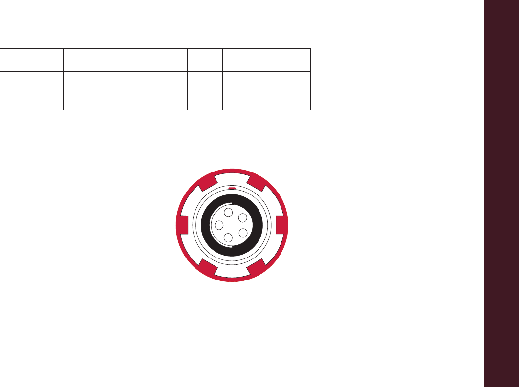
Specifications
ConnectorSpecifications
94
P/N:7010Ͳ1004
Power Connector
Rimmedinred,thepowerconnector(Figure 9Ͳ1)isasealedreceptacle,5pin,ODUpartnumberG80F1CͲT05QF00Ͳ0000.
Figure 9-1. Power Connector
Digital/Satel BNC ModemI/O I/O RF/GSM
input/outputto/from
modemantenna
Table 9-1. Modem Connector Specifications
Modem Type Signal Type Dir Details
1
2
3
45

Specifications
ConnectorSpecifications
95
P/N:7010Ͳ1004
Table 9Ͳ2describespowerconnectorspecifications.
Table 9-2. Power Connector Specifications
Number Signal Name Dir Details
1Power_INPP9to21voltsDCinput
2Power_INPP9to21voltsDCinput
3 Power_GND P Ground,powerreturn
4 Power_GND P Ground,powerreturn
5Aux_PowerP9to21voltsDCinput
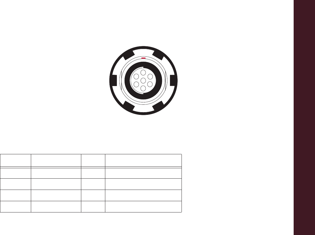
Specifications
ConnectorSpecifications
96
P/N:7010Ͳ1004
Serial C-RS232 Connector
Rimmedinblack,theserialRS232connector(Figure 9Ͳ2)isasealedreceptacle,7pin,ODUpartnumberG80F1CͲT07QC00Ͳ0000.
Figure 9-2. Serial RS232 Connector
Table 9Ͳ3givestheRS232cableconnectorspecifications.
Table 9-3. RS232 Connector Specifications
Number Signal Name Dir Details
1Notused
2GND ͲSignalground
3CTS ICleartosend
4RTS ORequesttosend
1
2
3
4
5
6
7
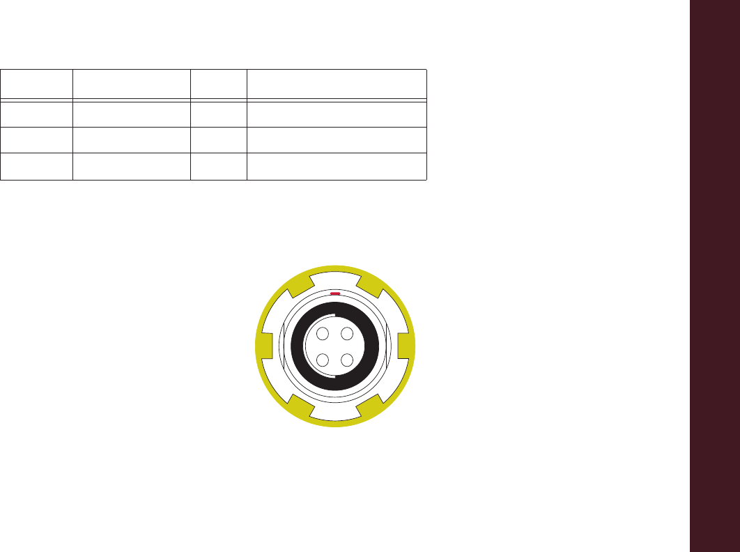
Specifications
ConnectorSpecifications
97
P/N:7010Ͳ1004
USB Connector
Rimmedinyellow,theUSBconnectorisasealedreceptacle,4pinTPScableconnector(Figure 9Ͳ3).
Figure 9-3. USB Connector for GGD Options
5 RXD I Receivedata
6TXD OTransmitdata
7Notused
Table 9-3. RS232 Connector Specifications (Continued)
Number Signal Name Dir Details
12
3 4

Specifications
ConnectorSpecifications
98
P/N:7010Ͳ1004
Table 9Ͳ4givestheUSBconnectorspecifications.
Table 9-4. USB Specifications
Number Signal Name Dir Details
1USB_PWRPBuspowerinput
2USBDͲI/O Dataminus
3USBD+ I/O Dataplus
4GND ͲGround

SafetyWarnings
99
P/N:7010Ͳ1004
• • • • • •
Safety Warnings
General Warnings
TocomplywithRFexposurerequirements,maintainatleast25cmbetweentheuserandthereceiverwhen
operatingLongLINKtechnology.
TPSreceiversaredesignedforsurveyandsurveyrelateduses(thatis,surveyingcoordinates,distances,anglesand
depths,andrecordingsuchmeasurements).Thisproductshouldneverbeused:
•
Withouttheuserthoroughlyunderstandingthismanual.
•
Afterdisablingsafetysystemsoralteringtheproduct.
•
Withunauthorizedaccessories.
•
Withoutpropersafeguardsatthesurveysite.
•
Contrarytoapplicablelaws,rules,andregulations.

Safety Warnings
BatteryWarnings
100
P/N:7010Ͳ1004
Battery Warnings
Neverattempttoopenthecasingofthedetachablebatteries!LithiumͲIonbatteriescanbedangerousif
mishandled!
Donotincinerateorheatthebatteryabove212degreesfahrenheit(100degreescelsius).Excessiveheatcan
causeseriousdamageandpossibleexplosion.
TamperingwiththebatteriesbyendusersornonͲfactoryauthorizedtechnicianswillvoidthebattery’s
warranty.
•Donotdisassemblethebatteries.
•Donotchargeinconditionsdifferentthanspecified.
•Donotuseotherthanthespecifiedbatterycharger.
•Donotshortcircuit.
•Donotcrushormodify.

Safety Warnings
ReceiverWarnings
101
P/N:7010Ͳ1004
Receiver Warnings
Usage Warnings
TamperingwiththereceiverbytheendusersornonͲfactoryauthorizedtechnicianswillvoidthereceiver’s
warranty:
•Donotattempttoopenthereceiverandmodifyanyofitsinternalcomponents.
•Donotchargeinconditionsdifferentthanspecified.
•Donotshortcircuit.
Ifthisproducthasbeendropped,altered,transportedorshippedwithoutproperpackaging,orotherwise
treatedwithoutcare,erroneousmeasurementsmayoccur.
Theownershouldperiodicallytestthisproducttoensureitprovidesaccuratemeasurements.
InformTPSimmediatelyifthisproductdoesnotfunctionproperly.
OnlyallowauthorizedTo pconwarrantyservicecenterstoserviceorrepairthisproduct.

Regulatory
102
P/N:7010Ͳ1004
• • • • • •
Regulatory
Thefollowingsectionsprovideinformationonthisproduct’scompliancewithgovernmentregulationsforuse.
FCC Compliance
ThisequipmentcomplieswithFCCradiationexposurelimitssetforthforuncontrolledequipmentandmeetstheFCCradio
frequency(RF)ExposureGuidelinesinSupplementCtoOET65.ThisequipmenthasverylowlevelsofRFenergythatitdeemedto
complywithoutmaximumpermissiveexposureevaluation(MPE).Butitisdesirablethatitshouldbeinstalledandoperatedwith
atleast30cm and morebetweenthe radiator andperson’sbody(excluding extremities: hands, wrists,feet andankles).
ThisequipmenthasbeentestedandfoundtocomplywiththelimitsforaClassAdigitaldevicepursuanttopart15oftheFCCrules.
Theselimitsaredesignedtoprovidereasonableprotectionagainstharmfulinterferencewhentheequipmentisoperatedina
commercialenvironment.Thisequipmentgenerates,uses,andcanradiateradiofrequencyenergyand,ifnotinstalledandused
inaccordancewiththeinstructionmanual,maycauseharmfulinterferencetoradiocommunications.Operationofthisequipment
inaresidentialareaislikelytocauseharmfulinterferenceinwhichcasetheuserwillberequiredtocorrecttheinterferenceathis
ownexpense.
Ifthisequipmentdoescauseinterferencetoradioortelevisionequipmentreception,whichcanbedeterminedbyturningthe
equipmentoffandon,theuserisencouragedtotrytocorrecttheinterferencebyoneormoreofthefollowingmeasures:
•
Reorientorrelocatethereceivingantenna.
•
Movetheequipmentawayfromthereceiver.
•
Plugtheequipmentintoanoutletonacircuitdifferentfromthattowhichthereceiverispowered.

Regulatory
IndustryCanadaCompliance
103
P/N:7010Ͳ1004
•
Consultthedealeroranexperiencedradio/televisiontechnicianforadditionalsuggestions.
Industry Canada Compliance
ThisequipmentcomplieswithICradiationexposurelimitssetforthforuncontrolledequipmentandmeetsRSSͲ102of
theICradiofrequency(RF)exposurerules.ThisequipmenthasverylowlevelsofRFenergythatitdeemedtocomply
withoutmaximumpermissiveexposureelevation(MPE).Bititisdesireablethatitshouldbeinstalledandoperatedwith
atleast30cmormorebetweentheradiatorandperson’sbody(excludingextremities:hands,wrists,feet,andankles).
ThisclassAdigitalapparatuscomplieswithCanadianICESͲ003.
Cet appareil numérique de la classe A est conforme à la norme NMB-003 du Canada.
ThisdevicecomplieswithIndustryCanadalicenceͲexemptRSSstandard(s).Operationissubjecttothefollowingtwo
conditions:(1)thisdevicemaynotcauseinterference,and(2)thisdevicemustacceptanyinterference,including
interferencethatmaycauseundesiredoperationofthedevice.
Le présent appareil est conforme aux CNR d’Industrie Canada applicables aux appareils radio exempts de
licence. L’exploitation est autorisée aux deux conditions suivantes : (1) l’appareil ne doit pas produire de
brouillage, et (2) l’utilisateur de l’appareil doit accepter tout brouilage radioélectrique subi, même si le
brouillage est susceptible d’en compromettre le fonctionnement.
Anychangesormodificationstotheequipmentnotexpresslyapprovedbythepartyresponsiblefor
compliancecouldvoidyourauthoritytooperatesuchequipment.

Regulatory
IndustryCanadaCompliance
104
P/N:7010Ͳ1004
IC RF Radiation Exposure Statement
Wheninstalling,locateorpointthisdeviceawayfromtheinstaller,soitdoesnotemitRFfieldinexcessofHealthCanada’slimits
forthegeneralpopulation.ConsultSafetyCode6fromHealthCanada’swebsiteatwww.hcͲsc.gc.ca/rpb.
IC Additional Statement with Detachable Antennas
Thisdevice9withUHFIImodem)hasbeendesignatedtooperatewiththeantennaslistedbelowandhaveamaximumgainof
2.4dBi.Antennasnotincludedinthisorhavingagaingreaterthan2.4dBiarestrictlyprohibitedforusewiththisdevice.The
requiredantennaimpedanceis50ohms.
GRͲ5UHFII2.4dBiwhipantenna
Manufacture/Type
420Ͳ450MHzLAIRDorANTENEX/G420BN
450Ͳ470MHzLAIRDorANTENEX/G450BN
Thedevice(withFH915modem)hasbeendesignatedtooperatewiththeantennaslistedbelowandhaveamaximumgainof
2.1dBi.Antennasnotincludedinthisorhavingagaingreaterthan2.1dBiarestrictlyprohibitedforusewiththisdevice.The
requiredantennaimpedanceis50ohms.
GRͲ5FH9152.1dBiSleeveDipoleAntenna
Manufacture/Type
890Ͳ960MHzLARSENSPDA17RP918
ConnectType:TNCmalereversepolarity

Regulatory
CommunityofEuropeCompliance
105
P/N:7010Ͳ1004
Community of Europe Compliance
TheproductdescribedinthismanualisincompliancewiththeR&TTEandEMCdirectivesfromtheEuropeanCommunity.
European Community Declaration of Conformity with R&TTE Directive
1999/5/EC
Thefollowingstandardswereapplied:(R&TTEDirective1999/5/EEC)
•
EN301489Ͳ1V1.8.1(2008Ͳ04)
•
EN301489Ͳ17V2.1.1(2009Ͳ05)
•
EN300328V1.7.1(2006Ͳ10)
•
EN60950Ͳ1:2006+A11:2009/A1:2010
•
EN301489Ͳ3V1.4.1(2002Ͳ08)
•
EN300440Ͳ2V1.4.1
ThefollowingCEmarkisaffixedtothedevice:
ThisisaClassAproduct.Inadomesticenvironmentthisproductmaycauseradiointerferenceinwhichcase
theusermayberequiredtotakeadequatemeasures.

Regulatory
DeclarationofConformity(R&TTEDirective1999/5/EC)
106
P/N:7010Ͳ1004
Declaration of Conformity (R&TTE Directive 1999/5/EC)
esky
[Czech]
(Topcon) tímto prohlašuje, že tento (GR-5) je ve shod se
základními požadavky a dalšími píslušnými ustanoveními smrnice
1999/5/ES.
Dansk
[Danish]
Undertegnede (Topcon) erklærer herved, at følgende udstyr
(GR-5) overholder de væsentlige krav og øvrige relevante krav i
direktiv 1999/5/EF.
Deutsch
[German]
Hiermit erklärt (Topcon) dass sich das Gerät (GR-5) in
Übereinstimmung mit den grundlegenden Anforderungen und den
übrigen einschlägigen Bestimmungen der Richtlinie 1999/5/EG
befindet.
Eesti
[Estonian]
Käesolevaga kinnitab (Topcon) seadme (GR-5) vastavust direktiivi
1999/5/EÜ põhinõuetele ja nimetatud direktiivist tulenevatele
teistele asjakohastele sätetele.
English Hereby, (Topcon) declares that this (GR-5) is in compliance with
the essential requirements and other relevant provisions of
Directive 1999/5/EC.
Español
[Spanish]
Por medio de la presente (Topcon) declara que el (GR-5) cumple
con los requisitos esenciales y cualesquiera otras disposiciones
aplicables o exigibles de la Directiva 1999/5/CE.
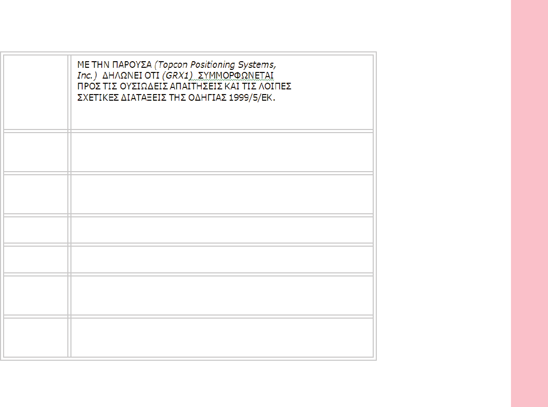
Regulatory
DeclarationofConformity(R&TTEDirective1999/5/EC)
107
P/N:7010Ͳ1004
[Greek]
Français
[French]
Par la présente (Topcon) déclare que l'appareil (GR-5) est
conforme aux exigences essentielles et aux autres dispositions
pertinentes de la directive 1999/5/CE.
Italiano
[Italian]
Con la presente (Topcon) dichiara che questo (GR-5) è conforme ai
requisiti essenziali ed alle altre disposizioni pertinenti stabilite dalla
direttiva 1999/5/CE.
Latviski
[Latvian]
Ar šo (Topcon) deklar, ka (GR-5) atbilst Direktvas 1999/5/EK
btiskajm prasbm un citiem ar to saisttajiem noteikumiem.
Lietuvi
[Lithuanian]
Šiuo (Topcon) deklaruoja, kad šis (GR-5) atitinka esminius
reikalavimus ir kitas 1999/5/EB Direktyvos nuostatas.
Nederlands
[Dutch]
Hierbij verklaart (Topcon) dat het toestel (GR-5) in
overeenstemming is met de essentiële eisen en de andere
relevante bepalingen van richtlijn 1999/5/EG.
Malti
[Maltese]
Hawnhekk, (Topcon), jiddikjara li dan (GR-5) jikkonforma mal-
tiijiet essenzjali u ma provvedimenti orajn relevanti li hemm fid-
Dirrettiva 1999/5/EC.

Regulatory
DeclarationofConformity(R&TTEDirective1999/5/EC)
108
P/N:7010Ͳ1004
Magyar
[Hungarian]
Alulírott, (Topcon) nyilatkozom, hogy a (GR-5) megfelel a
vonatkozó alapvetõ követelményeknek és az 1999/5/EC irányelv
egyéb elõírásainak.
Polski
[Polish]
Niniejszym, (Topcon) , deklaruj, e (GR-5) spenia wymagania
zasadnicze oraz stosowne postanowienia zawarte Dyrektywie
1999/5/EC.
Português
[Portugues]
(Topcon) declara que este (GR-5) está conforme com os requisitos
essenciais e outras disposições da Directiva 1999/5/CE.
Slovensko
[Slovenian]
(Topcon) izjavlja, da je ta (GR-5) v skladu z bistvenimi zahtevami
in ostalimi relevantnimi doloili direktive 1999/5/ES.
Slovensy
[Slovak]
(Topcon) týmto vyhlasuje, že (GR-5) spa základné požiadavky a
všetky príslušné ustanovenia Smernice 1999/5/ES.
Suomi
[Finnish]
(Topcon) vakuuttaa täten että (GR-5) tyyppinen laite on direktiivin
1999/5/EY oleellisten vaatimusten ja sitä koskevien direktiivin
muiden ehtojen mukainen.
Svenska
[Swedish]
Härmed intygar (Topcon) att denna (GR-5) står I
överensstämmelse med de väsentliga egenskapskrav och övriga
relevanta bestämmelser som framgår av direktiv 1999/5/EG.
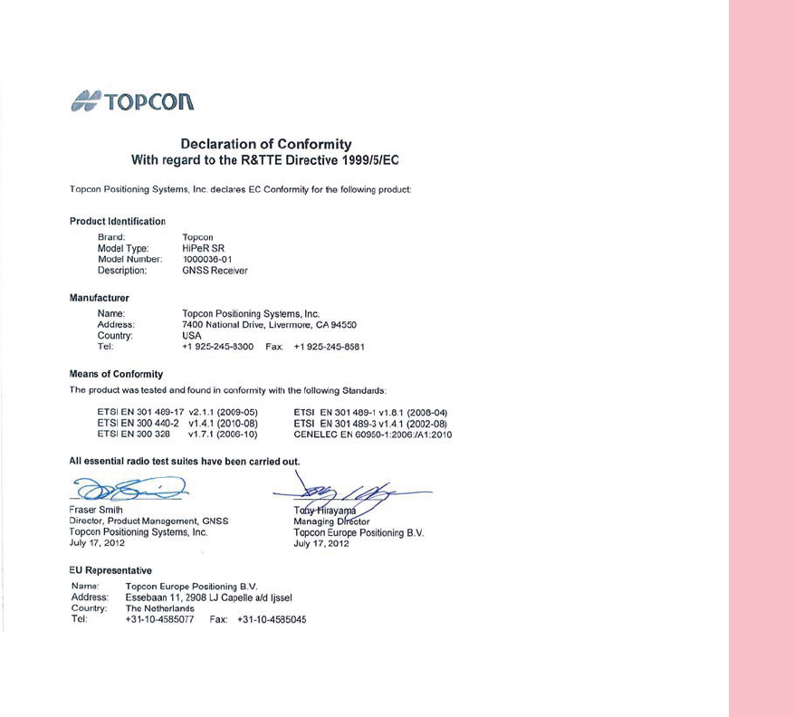
Regulatory
DeclarationofConformity(R&TTEDirective1999/5/EC)
109
P/N:7010Ͳ1004

Regulatory
WEEEDirective
110
P/N:7010Ͳ1004
WEEE Directive
FollowinginformationisforEUͲmemberstatesonly:
Theuseofthesymbolbelowindicatesthatthisproductmaynotbetreatedashouseholdwaste.Byensuringthisproductis
disposedofcorrectly,tohelppreventpotentialnegativeconsequencesfortheenvironmentandhumanhealth,whichcould
otherwisebecausedbyinappropriatewastehandlingofthisproduct.FormoredetailedinformationaboutthetakeͲbackand
recyclingofthisproduct,pleasecontactasupplierwhereyoupurchasedtheproductorconsult.
Bluetooth Transmission Statements/Compliance
ThisBluetoothdeviceiscomplianttothefollowingprofilesofthecorespecversion2.1/2.1+EDR:
•
Baseband
•
HCI
•
LinkManager
•
Radio
Theradiohasbeentestedusingthemaximumantennagainof2.3dBiandtheBluetoothqualificationisvalidforanyantenna
withthesameorlessgain.

Regulatory
KoreanKCͲRFCompliance
111
P/N:7010Ͳ1004
Korean KC-RF Compliance
䚨Gⱨ㉔㉘⽸⏈G㤸䑀䝰㐔Gᴴ⏙㉥㢨G㢼㡰⦐G㢬⮹㙼㤸ḰGḴ⥜═G㉐⽸㏘⏈G䚔G㍌G㛺㏩⏼␘ UG
ⱨ㉔㇠㛅GGO~GPaGiGYUXGRGlky
㇠㟝㨰䑀㍌GO|GmPaGGY[WYTY[_WGt
㵸≄G㍌GGOGGGPaGG^`
ḩ㩅㉔㤸⥙GGGOhGwPaGYUXGi
ⷴ㦤ⵝ㐑GGO{GGGPaGnmzrSG_wzr
㢬㫑㥉⸨ GOwGpGjPa KCC-CRM-T8S-1000036-01
㐔㷡㣄G GOhPa {GwGzSGpU
ὤὤ⮹㾡G GO{GGPaGnwzGGGGGiG
⯜⒬G㢨⪸ GOtGuPaGGnyT\GGnzY
㥐㦤㜤㠈GGGGGGGGGOGGPaGGYWXY
㥐㦤㣄GⵃG㥐㦤ạᴴGGOtGGGGPaGwjGwGSGj
㢬㫑㣄G㐑ⷸG⺴䝬GGGGGGGOhGjPaG{_z
Korean KC-EMC Class A Statement
㢨Gὤὤ⏈G㛹ⱨ㟝 Oh Ἵ PG㤸㣄䑀G㤵䚝ὤὤ⦐㉐G䑄⬘㣄G❄⏈G㇠㟝㣄⏈G㢨G㥄㡸G㨰㢌䚌㐐ὤGⵈ⢰⮤ SG
ᴴ㥉㞬㢌G㫴㜡㜄㉐G㇠㟝䚌⏈Gᶷ㡸G⯝㤵㡰⦐G䚝⏼␘ U

Warranty
112
P/N:7010Ͳ1004
• • • • • •
Warranty
Topconlaserandelectronicpositioningequipmentareguaranteedagainstdefectivematerialandworkmanshipundernormaluse
andapplicationconsistentwiththisManual.Theequipmentisguaranteedfortheperiodindicated,onthewarrantycard
accompanyingtheproduct,startingfromthedatethattheproductissoldtotheoriginalpurchaserbyTopcon’sAuthorized
Dealers.
1
Duringthewarrantyperiod,Topconwill,atitsoption,repairorreplacethisproductatnoadditionalcharge.Repairpartsand
replacementproductswillbefurnishedonanexchangebasisandwillbeeitherreconditionedornew.Thislimitedwarrantydoes
notincludeservicetorepairdamagetotheproductresultingfromanaccident,disaster,misuses,abuseormodificationofthe
product.
WarrantyservicemaybeobtainedfromanauthorizedTop conwarrantyservicedealer.Ifthisproductisdeliveredbymail,
purchaseragreestoinsuretheproductorassumetheriskoflossordamageintransit,toprepayshippingchargestothewarranty
servicelocationandtousetheoriginalshippingcontainerorequivalent.Alettershouldaccompanythepackagefurnishinga
descriptionoftheproblemand/ordefect.
Thepurchaser’ssoleremedyshallbereplacementasprovidedabove.InnoeventshallTopcon beliableforanydamagesorother
claimincludinganyclaimforlostprofits,lostsavingsorotherincidentalorconsequentialdamagesarisingoutoftheuseof,or
inabilitytouse,theproduct.
1. The warranty against defects in a Topcon battery, charger, or cable is 90 days.

Glossary
113
P/N:7010Ͳ1004
• • • • • •
Glossary
B
BaseStation
–AGNSSreceiversetupoveraknownpoint,whichisusedtoderivecorrectioninformationfornearbyRover(mobile)
GNSSreceivers.
Bluetooth®–
Oftenusedinplaceofcables,Bluetoothisopenwirelesstechnologyforexchangingdataovershortdistancesfrom
fixedandmobiledevices.
C
COMPASS
–BeiDouNavigationSatelliteSystemmaintainedandoperatedbyChina.
G
GALILEO
–ThesatellitesystemcurrentlybeingmaintainedandoperatedbytheEuropeanUnion(EU)andEuropeanSpaceAgency
(ESA).
GGD
–GPS+GLONASSDualFrequencysignaltracking.
GLONASS–
TheGLObalNAvigationSatelliteSystemmaintainedandoperatedbytheRussianFederation.
GNSS–
GlobalNavigationSatelliteSystems,suchasGPSandGLONASS.
GPS–
TheGlobalPositioningSystemmaintainedandoperatedbytheUnitedStatesDepartmentofDefense.

Glossary
114
P/N:7010Ͳ1004
L
L1
–TheprimaryLͲbandcarrierusedbyGPSandGLONASSsatellitestotransmitsatellitedata.
L2
–ThesecondaryLͲbandcarrierusedbyGPSandGLONASSsatellitestotransmitsatellitedata.
LightͲEmittingDiode(LED)
–Usedasindicatorlightsonthereceivertodisplaythestatusofthereceiver’scomponentsand
controlreceiveroperations.
M
MAGNETField™
–DatacontrollersoftwarethatispartoftheMAGNETsoftwaresystem.
MAGNETOffice™
–PostͲprocessingandCADsolutionsoftwareforsurveyingandgradeapplication.ItispartoftheMAGNET
softwaresystem.
MINTER–
Thereceiver’sMinimumINTERfaceusedtodisplayandcontroldatainputandoutput.
N
NetworkRTK–
CollectssatelliteobservationsfromthereferencestationswithinthenetworkandsendsRTKcorrectionstothe
Rover.
O
OptionAuthorizationFile(OAF)–
Thisenablesthespecificfeaturesthatacustomerpurchases.
P

Glossary
115
P/N:7010Ͳ1004
PhaseCenterofAntenna
–Thepointfromwhichtheelectromagneticradiationspreadssphericallyoutward,withthephaseof
thesignalbeingequalatanypointonthesphere.
PocketͲ3D–
FieldcontrollersoftwarebyTopconthatsupportsbothGNSSandTS.
R
RealͲTimeKinematic(RTK)–
AprecisemethodofrealͲtimesurveying.RTKenablesyoutocheckthemeasurementquality
withouthavingtoprocessthedata.
RootMeanSquare(RMS)
–Statisticalmeasureofthemagnitudeofavaryingquantity.
Rover–
AmobileGNSSreceiveranddatacollectorusedfordetermininglocationinthefield.
S
SatelliteͲBasedAugmentationSystems(SBAS)–
Complementsexistingglobalnavigationsystems.SBAStransmitsdifferential
correctionsandmessagesfornavigationsatellitesthatarewithinsightofanetworkorreferencestationsinawidearea,such
asacontinent.
StaticSurvey–
Typicallyusesanetworkormultiplebaselineapproachforpositioning.Thismethodprovidesthehighest
accuracyandrequiresthelongestobservationtimes.
T
TopconReceiverUtility(TRU)–
Hardwareconfigurationsoftwareforreceiversandperipheraldevices.TRUisincludedonthe
GPS+SoftwareCDthataccompaniedyourreceiver.
U

Glossary
116
P/N:7010Ͳ1004
UniversalSerialBus(USB)–
Aconnectionstandardusedbydevices,suchasareceiver,controller,computer,etc.