TransCore F4-06476-LP RFID Bar Code Printer User Manual Part 2
TransCore RFID Bar Code Printer Part 2
UserManual.wiki
>
TransCore
>
F4-06476-LP User Manual
>
User manual Part 2
Contents
1.
User manual Part 1
2.
User manual Part 2
3.
User manual Part 3
4.
User Manual Update
User manual Part 2
Navigation menu
Upload a User Manual
Namespaces
Wiki Guide
HTML
PDF
Info
Views
User Manual
Discussion / Help
Navigation
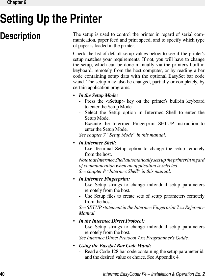
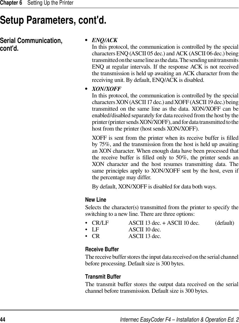
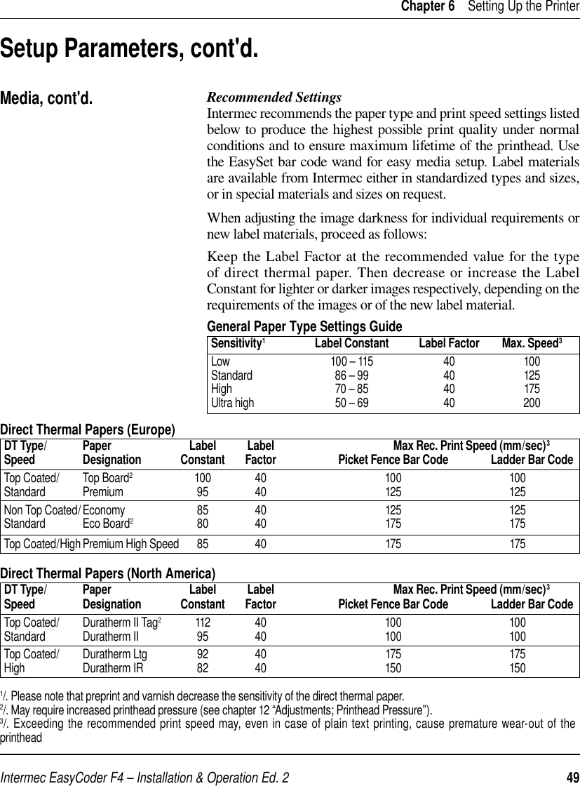
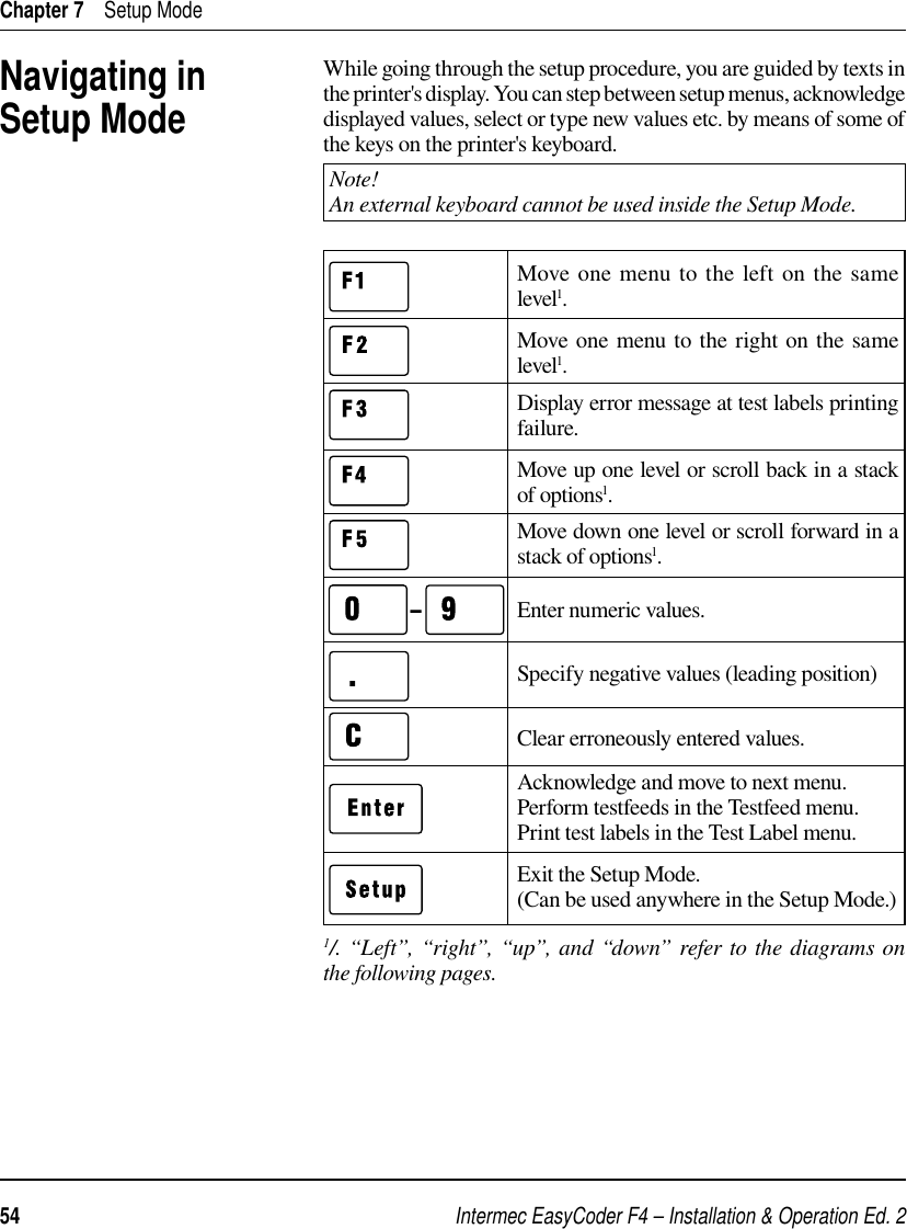
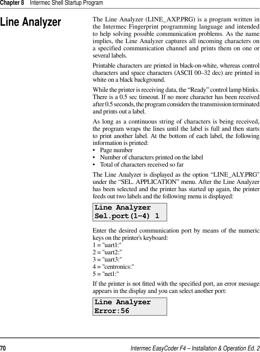
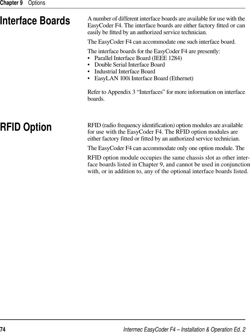
![Intermec EasyCoder F4 – Installation & Operation Ed. 246 Chapter 6 Setting Up the PrinterThe media setup tells the fi rmware the characteristics of the of media that will be used, so the printout will be positioned correctly on the paper and get the best quality possible.Media SizeThe size of the printable area is defi ned by three parameters; X-Start, Width, and Length.X-StartX-start specifi es the position of the origin along the dots on the printhead. By default, X-start is 24 dots, which places the inner margin of the print area 3 mm (0.118") from the inner edge of the paper and gives a maximum print width of 808 dots (101 mm/3.976"). If you want to make use of the entire paper width, reset the X-start value to 0 which gives a maximum print width of 832 dots (104 mm/4.095").By increasing the value for the X-start parameter, the origin will be moved outwards, away from the inner edge of the web. In other words, the larger X-start value – the wider inner margin and the less available print width.WidthWidth specifi es the width of the printable area and is defi ned as a number of dots from the origin. The sum of the X-start value and the width value gives the outer margin of the printable area. The width must not be so large as to allow printing outside the paper web and must not exceed 832.LengthLength decides the length of the printable area from origin and along the Y-coordinate as a number of dots by allocating memory space in the printer's temporary memory. Two identical image buffers are created. The size of each buffer can be calculated using this formula:Buffer size (bits) = [Print length in dots] x [Printhead width in dots]Note that the temporary memory has other functions that also require some memory space. To obtain a longer print area, the memory can be increased by fi tting a larger DRAM SIMM on the printer's CPU board as described in the Service Manual. Setup Parameters, cont'd.Media• Media Size• Media Type• Paper Type• Testfeed• Contrast](https://usermanual.wiki/TransCore/F4-06476-LP.User-manual-Part-2/User-Guide-98734-Page-10.png)
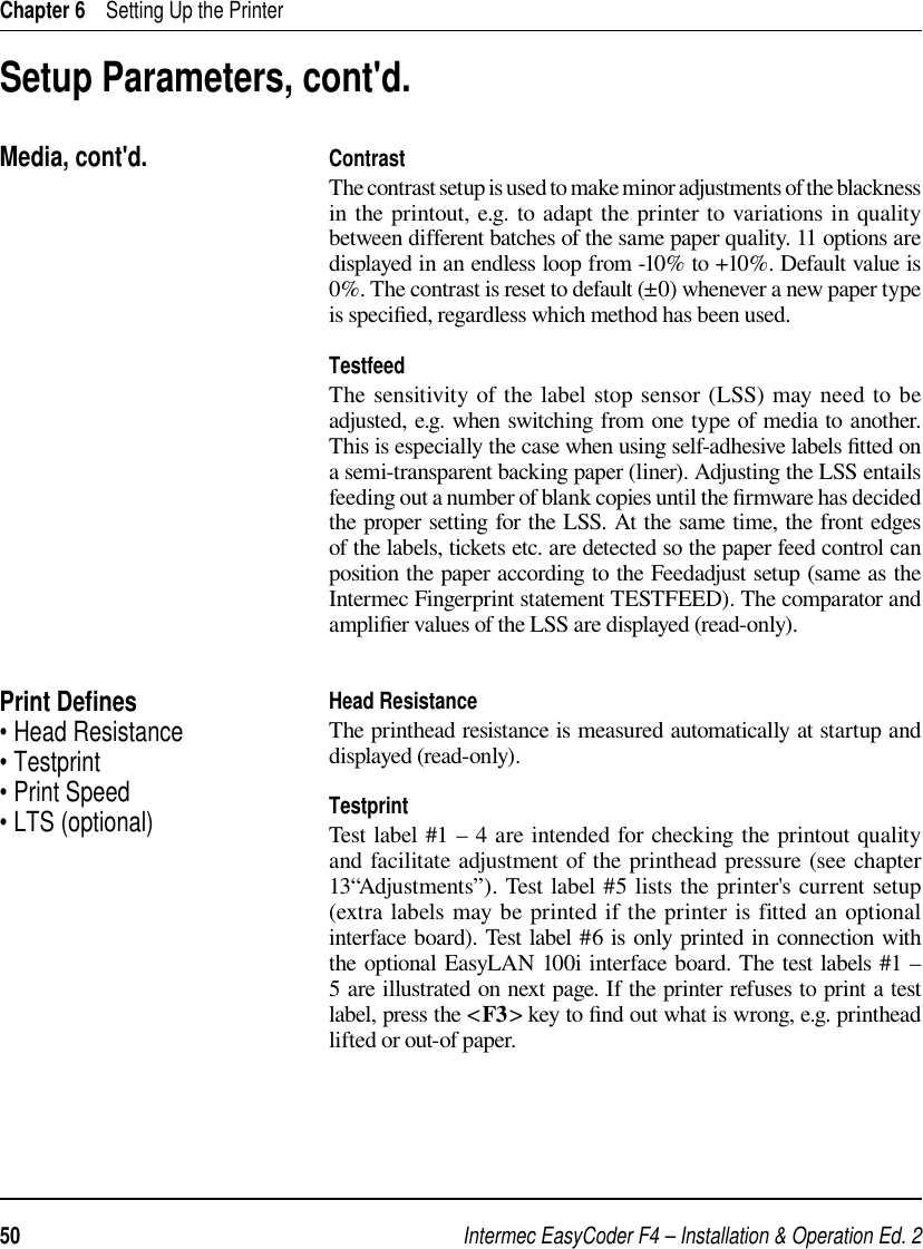
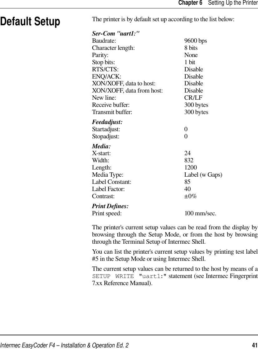
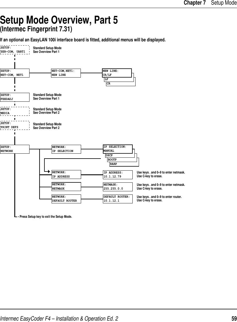
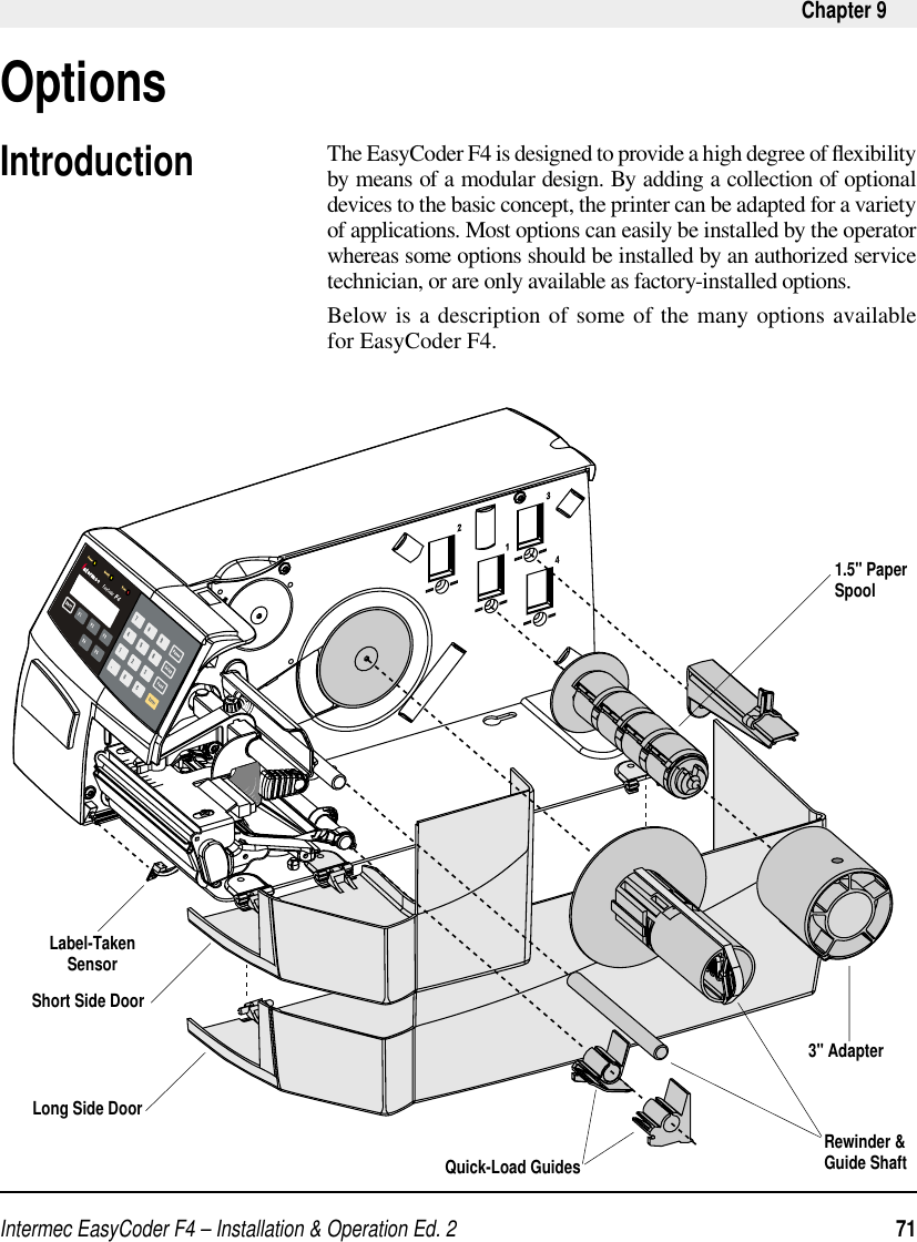
![Intermec EasyCoder F4 – Installation & Operation Ed. 2 51 Chapter 6 Setting Up the PrinterSetup Parameters, cont'd.Print Defi nes, cont'd.Test Label #1 Test Label #2Test Label #3 Test Label #4Test Label #5681 ohms/8 dotsUART1 9600-8-N-1RTS/CTS DISABLEENQ/ACK DISABLEXON/XOFF DATA TO HOST DISABLE DATA FROM HOST DISABLENEW LINE CR/LFREC BUF 300TRANS BUF 300PRINT CONFIGSTARTADJ 0STOPADJ 0XSTART 24WIDTH 808LENGTH 1800MEDIA TYPE LABEL (w GAPS)PAPER TYPE DIRECT THERMALLABEL CONSTANT 85LABEL FACTOR 40CONTRAST +0%TESTFEED 12 3HEAD RESIST 681PRINT SPEED 100 Odometer [km] 0Model F4 Hardware version 3.0 Ram 4096 ( k) Flash 0+2048 +1016 (k) External 0 (k) c: 1819504 bytes freeFIRMWARE Fingerprint 7.31 MCS1147 xx-xx-00 xx:xx:xx m3k slav0782 27-MAY-97 17:09:25 [0] No keyboard slave [1]](https://usermanual.wiki/TransCore/F4-06476-LP.User-manual-Part-2/User-Guide-98734-Page-15.png)
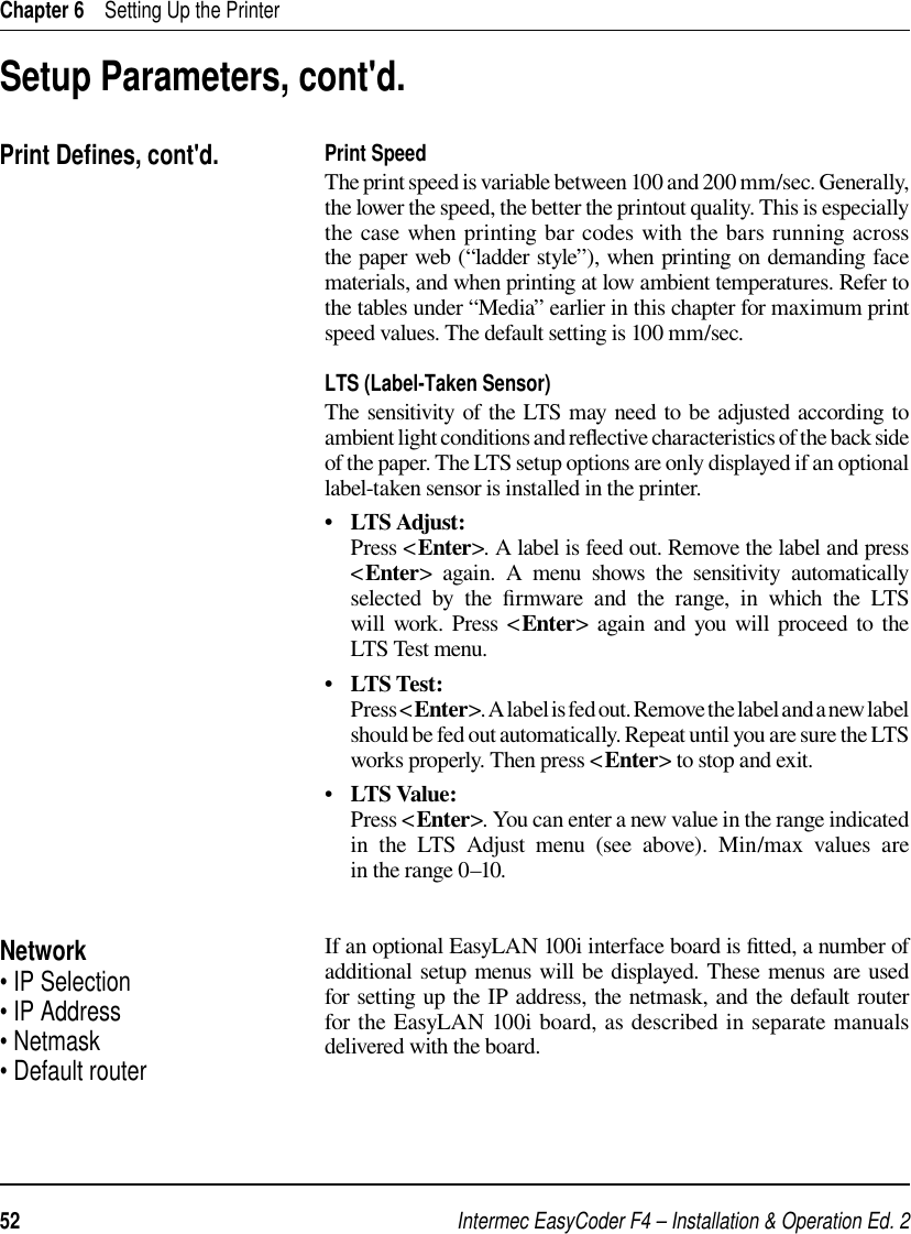
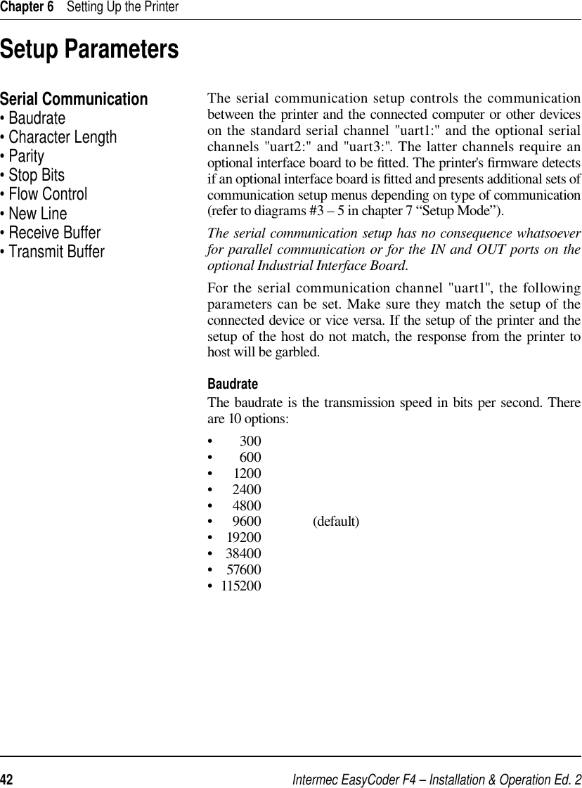
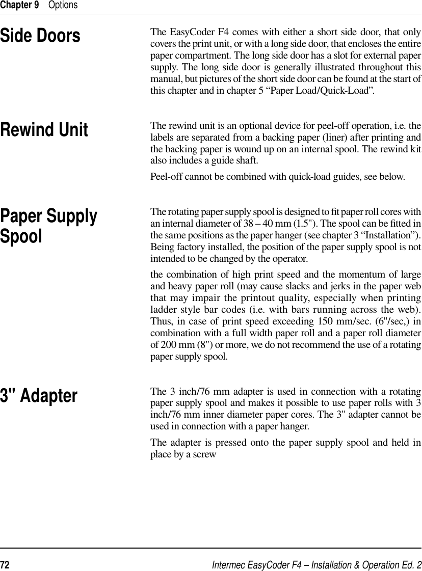
![Intermec EasyCoder F4 – Installation & Operation Ed. 2 55 Chapter 7 Setup ModeSetup Mode Overview, Part 1 (Intermec Fingerprint 7.31)48002400SETUP:SER-COM,UART2SETUP:SER-COM,UART11200600300115200576003840019200SER-COM,UART1:BAUDRATEBAUDRATE:9600SPACEMARKODDEVENSER-COM,UART1:PARITYPARITY:NONE7SER-COM,UART1:CHAR LENGTHCHAR LENGTH:82SER-COM,UART1:STOP BITSSTOPBITS:1SER-COM,UART1:FLOWCONTROLFLOWCONTROL:RTS/CTSENABLERTS/CTS:DISABLEFLOWCONTROL:ENQ/ACKENABLEENQ/ACK:DISABLEFLOWCONTROL:XON/XOFFXON/XOFF:DATA TO HOSTENABLEDATA TO HOST:DISABLEXON/XOFF:DATA FROM HOSTENABLEDATA FROM HOST:DISABLECRLFSER-COM,UART1:NEW LINENEW LINE:CR/LFSER-COM,UART1:REC BUFREC BUF:[300]:SER-COM,UART1:TRANS BUFTRANS BUF:[300]:DETECTION:FEEDADJSETUP:FEEDADJFEEDADJ:STOPADJSTOPADJ:[0]:STARTADJ:[0]:Continued on next page!LEGEND:Boxes with thick lines indicate default setupBoxes with dotted lines indicate menus related tooptional interface boards.FEEDADJ:STARTADJSee Overview Part 3See Overview Part 4See Overview Part 5SETUP:SER-COM,UART3SETUP:NET-COM,NET1](https://usermanual.wiki/TransCore/F4-06476-LP.User-manual-Part-2/User-Guide-98734-Page-19.png)
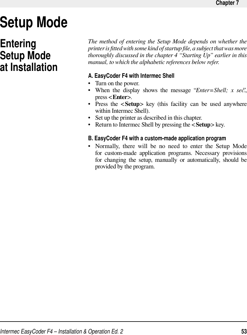
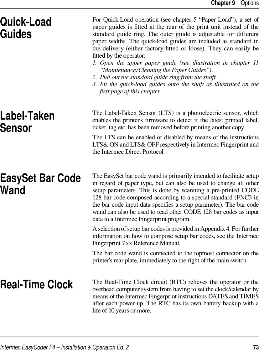
![Intermec EasyCoder F4 – Installation & Operation Ed. 256 Chapter 7 Setup ModeSetup Mode Overview, Part 2(Intermec Fingerprint 7.31)VAR LENGTH STRIPFIX LENGTH STRIPTICKET (w GAPS)TICKET (w MARK)MEDIA:MEDIA SIZEMEDIA:CONTRASTSETUP:MEDIAUse <F5> to select type of test label.Press <Enter> to print it.If no label is printed, press <F3> for error message. • Press Setup key to exit the Setup Mode.MEDIA SIZE:XSTARTMEDIA SIZE:WIDTHMEDIA SIZE:LENGTHXSTART:[24]:WIDTH:[832]:LENGTH:[1200]:MEDIA:MEDIA TYPEMEDIA TYPE:LABEL (w GAPS)-2%-4%-6%-8%-10%MEDIA TYPE:+10%+8%+6%+4%+2%CONTRAST:+0%PRINT DEFS:HEAD RESISTSETUP:PRINT DEFSSETUP:NETWORKHEAD RESIST:[nnn]:PRINT DEFS:TESTPRINT<ENTER> = PRINT:<F5> = NEXT #1Read-only value.Printhead resistance isautomatically set at startup.The LTS setup menus areonly displayed if an optionalLTS (Label-Taken Sensor)is installed in the printer.Continued from previous page!PRINT SPEED:[100]:PRINT DEFS:PRINT SPEEDLTS:LTS ADJUSTPRINT DEFS:LTSLTS:LTS TESTLTS:LTS VALUEREMOVE LABEL AND PRESS ENTER SENSITIVITY 10 OUT OF 9–10 REMOVE LABEL ENTER TO STOPLTS VALUE:[10]:MEDIA:PAPER TYPEPAPER TYPE:DIRECT THERMALMEDIA:TESTFEEDTESTFEED:[14 1]• Press Enter key to perform a Testfeed.• Comparator and amplifier values are read-only. DIRECT THERMAL:LABEL CONSTANTDIRECT THERMAL:LABEL FACTORLABEL CONSTANT:[85]:LABEL FACTOR:[40]:See Overview Part 5](https://usermanual.wiki/TransCore/F4-06476-LP.User-manual-Part-2/User-Guide-98734-Page-20.png)
![Intermec EasyCoder F4 – Installation & Operation Ed. 2 57 Chapter 7 Setup ModeSetup Mode Overview, Part 3(Intermec Fingerprint 7.31)4800SETUP:SER-COM,UART224001200600300576003840019200SER-COM,UART2:BAUDRATEBAUDRATE:9600SPACEMARKODDEVENSER-COM,UART2:PARITYPARITY:NONE7SER-COM,UART2:CHAR LENGTHCHAR LENGTH:82SER-COM,UART2:STOP BITSSTOPBITS:1SER-COM,UART2:FLOWCONTROLFLOWCONTROL:RTS/CTSENABLERTS/CTS:DISABLEFLOWCONTROL:ENQ/ACKENABLEENQ/ACK:DISABLEFLOWCONTROL:XON/XOFFXON/XOFF:DATA TO HOST ENABLEDATA TO HOST:DISABLEXON/XOFF:DATA FROM HOSTENABLEDATA FROM HOST:DISABLECRLFSER-COM,UART2:NEW LINENEW LINE:CR/LFSER-COM,UART2:REC BUFREC BUF:[300]:SER-COM,UART2:TRANS BUFTRANS BUF:[300]:If an optional Double Serial or Industrial Interface Board is fitted, additional menus will be displayed(in case of Double Serial Interface Board, also see Overview Part 4): The selected type of hardware connection on "uart2:"is displayed as one of the following alternatives (read-only):• RS232• 422 NON ISOLATED• 422 ISOLATED• RS485These menus are only displayed if RS 485 is selected on "uart2:"Enter printer's protocol address (0–31).RTS/CTS flowcontrol cannot beselected for the following types ofhardware connection on "uart2:":• 422 NON ISOLATED• 422 ISOLATEDSER-COM,UART2:CONNECTED HWSER-COM,UART2:PROTOCOL ADDR.PROTOCOL ADDR.[1]:SETUP:SER-COM,UART3These menus are not displayed if RS 485 is selected on "uart2:"ENABLESER-COM,UART2:PROT ADDRPROT ADDR:DISABLEThese menus are only displayed if RS 485 is selected on "uart2:"INTELLITAGRCONECTED HW:RS232](https://usermanual.wiki/TransCore/F4-06476-LP.User-manual-Part-2/User-Guide-98734-Page-21.png)
![Intermec EasyCoder F4 – Installation & Operation Ed. 258 Chapter 7 Setup ModeSetup Mode Overview, Part 4(Intermec Fingerprint 7.31)4800SETUP:SER-COM,UART324001200600300576003840019200SER-COM,UART3:BAUDRATEBAUDRATE:9600SPACEMARKODDEVENSER-COM,UART3:PARITYPARITY:NONE7SER-COM,UART3:CHAR LENGTHCHAR LENGTH:82SER-COM,UART3:STOP BITSSTOPBITS:1SER-COM,UART3:FLOWCONTROLFLOWCONTROL:RTS/CTSENABLERTS/CTS:DISABLEFLOWCONTROL:ENQ/ACKENABLEENQ/ACK:DISABLEFLOWCONTROL:XON/XOFFXON/XOFF:DATA TO HOSTENABLEDATA TO HOST:DISABLEXON/XOFF:DATA FROM HOSTENABLEDATA FROM HOST:DISABLECRLFSER-COM,UART3:NEW LINENEW LINE:CR/LFSER-COM,UART3:REC BUFREC BUF:[300]:SER-COM,UART3:TRANS BUFTRANS BUF:[300]:If an optional Double Serial Interface Board is fitted, additional menus will be displayed:The selected type of hardware connection on "uart3:"is displayed as one of the following alternatives (read-only):• RS232• 422 NON ISOLATED• CURRENT LOOPRTS/CTS flowcontrol cannot beselected for the following types ofhardware connection on "uart3:":• 422 NON ISOLATED• 20 mA CURRENT LOOPSER-COM,UART3:CONNECTED HWCONNECTED HW:RS232](https://usermanual.wiki/TransCore/F4-06476-LP.User-manual-Part-2/User-Guide-98734-Page-22.png)
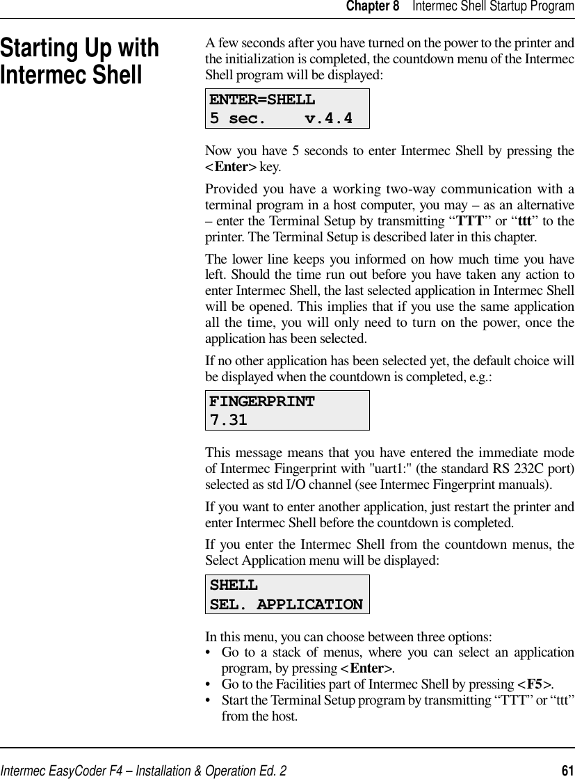
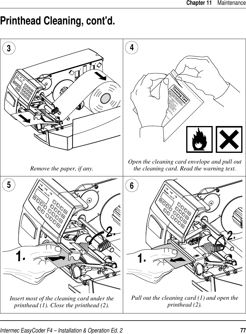
![Intermec EasyCoder F4 – Installation & Operation Ed. 276 Chapter 11MaintenancePrinthead CleaningCleaning of the printhead on a regular basis, preferably in connection with each ribbon or paper load, is important for the life of the printhead and for the printout quality. Below is a description of how to clean the printhead by means of Cleaning Cards. If additional cleaning is required, e.g. for removing adhesive residue from the platen roller or tear-off edge, use a cotton swab moistened with isopropyl alcohol.Caution!Isopropyl alcohol [(CH 3)2CHOH; CAS 67-63-0] is a highly fl ammable, moderately toxic and mildly irritating substance.Open the side door. Turn the printhead lift knob clockwise to lift the printhead.1 2](https://usermanual.wiki/TransCore/F4-06476-LP.User-manual-Part-2/User-Guide-98734-Page-40.png)