TransCore F4-06476-LP RFID Bar Code Printer User Manual Part 3
TransCore RFID Bar Code Printer Part 3
UserManual.wiki
>
TransCore
>
F4-06476-LP User Manual
>
User manual Part 3
Contents
1.
User manual Part 1
2.
User manual Part 2
3.
User manual Part 3
4.
User Manual Update
User manual Part 3
Navigation menu
Upload a User Manual
Namespaces
Wiki Guide
HTML
PDF
Info
Views
User Manual
Discussion / Help
Navigation
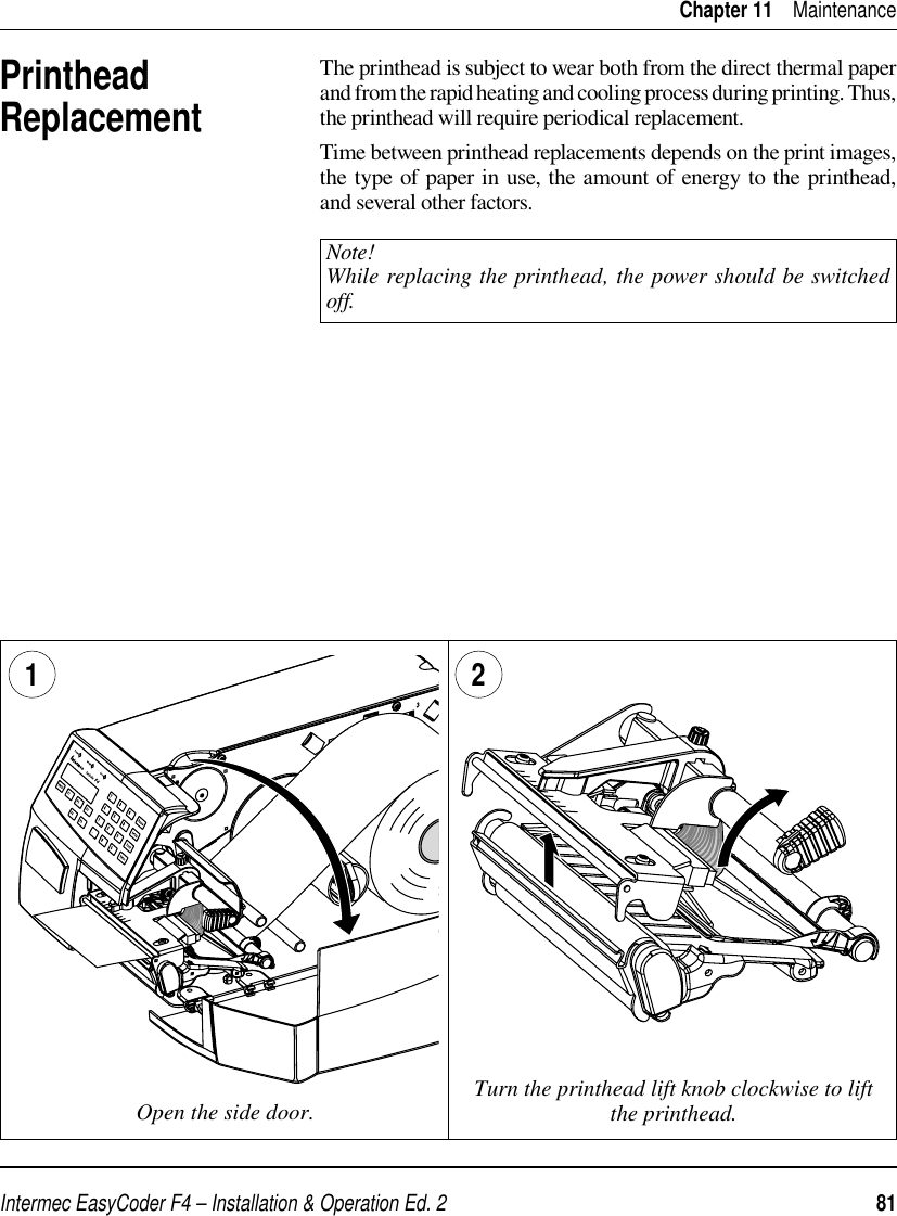
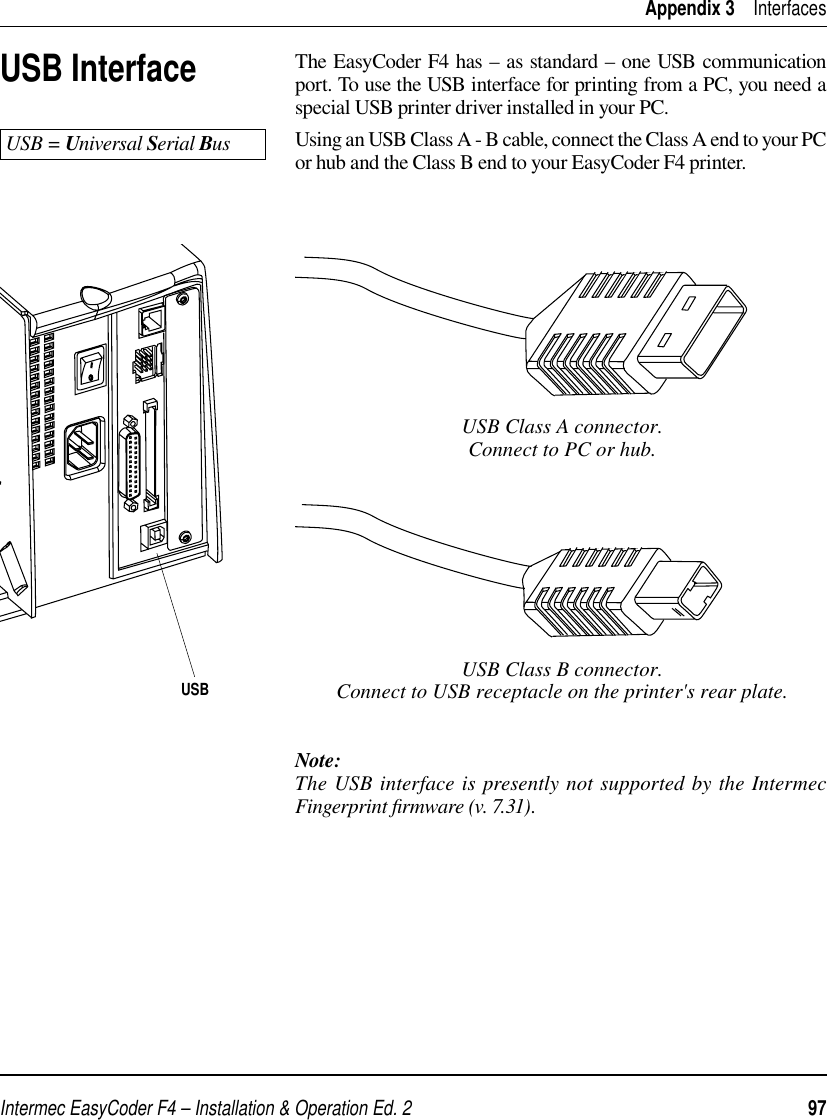
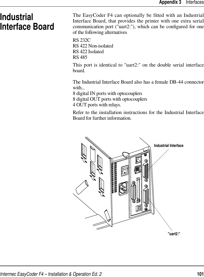
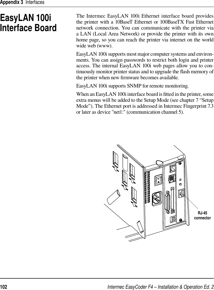
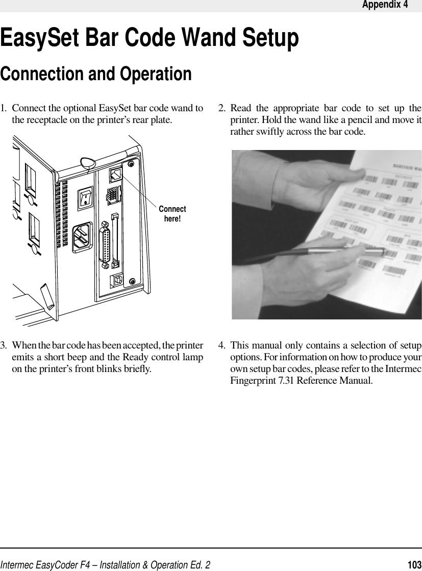
![Intermec EasyCoder F4 – Installation & Operation Ed. 280 Chapter 11 MaintenanceCleaning the Paper GuidesBoth parts of the label stop sensor, which controls the paper feed, are covered by plastic guides. The guides are provided with seemingly non-transparent areas, through which the light between the two parts of the label stop sensor is transmitted. These areas (indicated by a shade of grey in illustration #2 below) must be kept clean from dust, stuck labels, and adhesive residue.If the printer starts to feeed our labels in an unexpected way. lift the upper guide – as described below – and check for anything that may block the beam of light (dust, stuck labels, adhesive residue etc.). If necessary, clean the guides using a cleaning card or a soft cloth soaked with isopropyl alcohol. Do not use any other the of chemical. Be careful not to scratch the guides.Caution!Isopropyl alcohol [(CH 3)2CHOH; CAS 67-63-0] is a highly fl ammable, moderately toxic and mildly irritating substance. Lift the inner part of the upper guide and pull it outwards,disengaging it from the lower guide. Take care not to damage the cable.Tilt the upper guide upwards and clean the areas marked with grey. After cleaning, reas-semble in reverse order.1 2](https://usermanual.wiki/TransCore/F4-06476-LP.User-manual-Part-3/User-Guide-98735-Page-3.png)