TransCore F4-06476-LP RFID Bar Code Printer User Manual Part 3
TransCore RFID Bar Code Printer Part 3
Contents
- 1. User manual Part 1
- 2. User manual Part 2
- 3. User manual Part 3
- 4. User Manual Update
User manual Part 3
Intermec EasyCoder F4 – Installation & Operation Ed. 278
Chapter 11 Maintenance
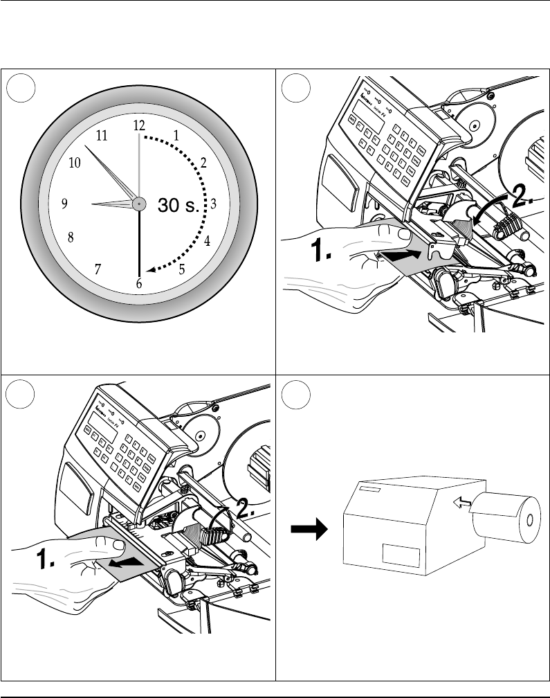
Printhead Cleaning, cont'd.
Wait for approx. 30 seconds to allow the
cleaning fl uid to dissolve the residue. Insert most of the cleaning card under the
printhead (1). Close the printhead (2).
9
Allow the cleaned parts to dry before loading
any paper.
Pull out the cleaning card. If necessary, repeat
the process with a new cleaning card.
87
10
Intermec EasyCoder F4 – Installation & Operation Ed. 2 79
Chapter 11 Maintenance
1
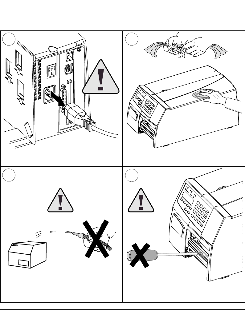
External Cleaning
Always remove the power cord
before cleaning! Wipe external surfaces with a soft cloth slightly
moistened with water or a mild detergent.
3
Never use any sharp tools for removing stuck
labels. The printhead and rollers are delicate.
Never spray the printer. Protect it from water
when cleaning the premises.
2
4
Intermec EasyCoder F4 – Installation & Operation Ed. 280
Chapter 11 Maintenance
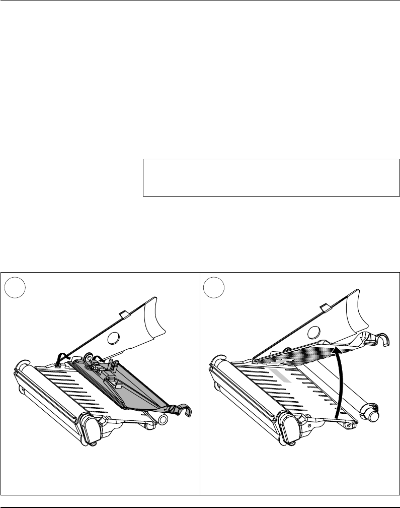
Cleaning the
Paper Guides
Both parts of the label stop sensor, which controls the paper feed, are
covered by plastic guides. The guides are provided with seemingly
non-transparent areas, through which the light between the two
parts of the label stop sensor is transmitted. These areas (indicated
by a shade of grey in illustration #2 below) must be kept clean from
dust, stuck labels, and adhesive residue.
If the printer starts to feeed our labels in an unexpected way. lift the
upper guide – as described below – and check for anything that may
block the beam of light (dust, stuck labels, adhesive residue etc.).
If necessary, clean the guides using a cleaning card or a soft cloth
soaked with isopropyl alcohol. Do not use any other the of chemical.
Be careful not to scratch the guides.
Caution!
Isopropyl alcohol [(CH
3)2CHOH; CAS 67-63-0] is a highly
fl ammable, moderately toxic and mildly irritating substance.
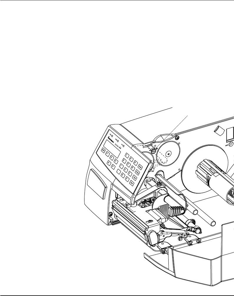
Lift the inner part of the upper guide and
pull it outwards,disengaging it from the lower
guide. Take care not to damage the cable.
Tilt the upper guide upwards and clean the
areas marked with grey. After cleaning, reas-
semble in reverse order.
1 2
Intermec EasyCoder F4 – Installation & Operation Ed. 2 81
Chapter 11 Maintenance
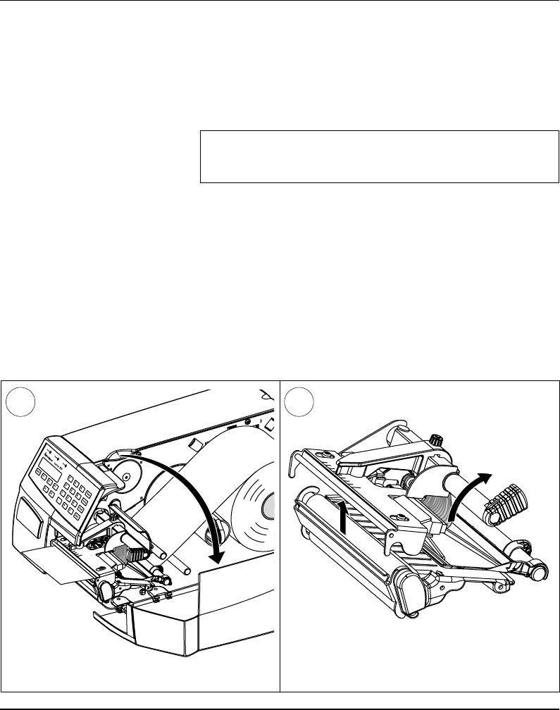
Printhead
Replacement
The printhead is subject to wear both from the direct thermal paper
and from the rapid heating and cooling process during printing. Thus,
the printhead will require periodical replacement.
Time between printhead replacements depends on the print images,
the type of paper in use, the amount of energy to the printhead,
and several other factors.
Note!
While replacing the printhead, the power should be switched
off.
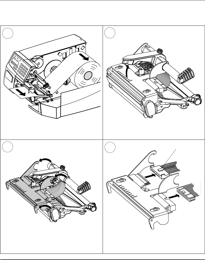
Open the side door. Turn the printhead lift knob clockwise to lift
the printhead.
1 2
Intermec EasyCoder F4 – Installation & Operation Ed. 282
Chapter 11 Maintenance
Printhead Replacement, cont'd.
Pull the printhead bracket away from the
magnet in the pressure arm.
34
Disconnect the printhead bracket from the print
mechanism – as indicated by the arrows – and
pull out the printhead as far as the cables allow.
6
5
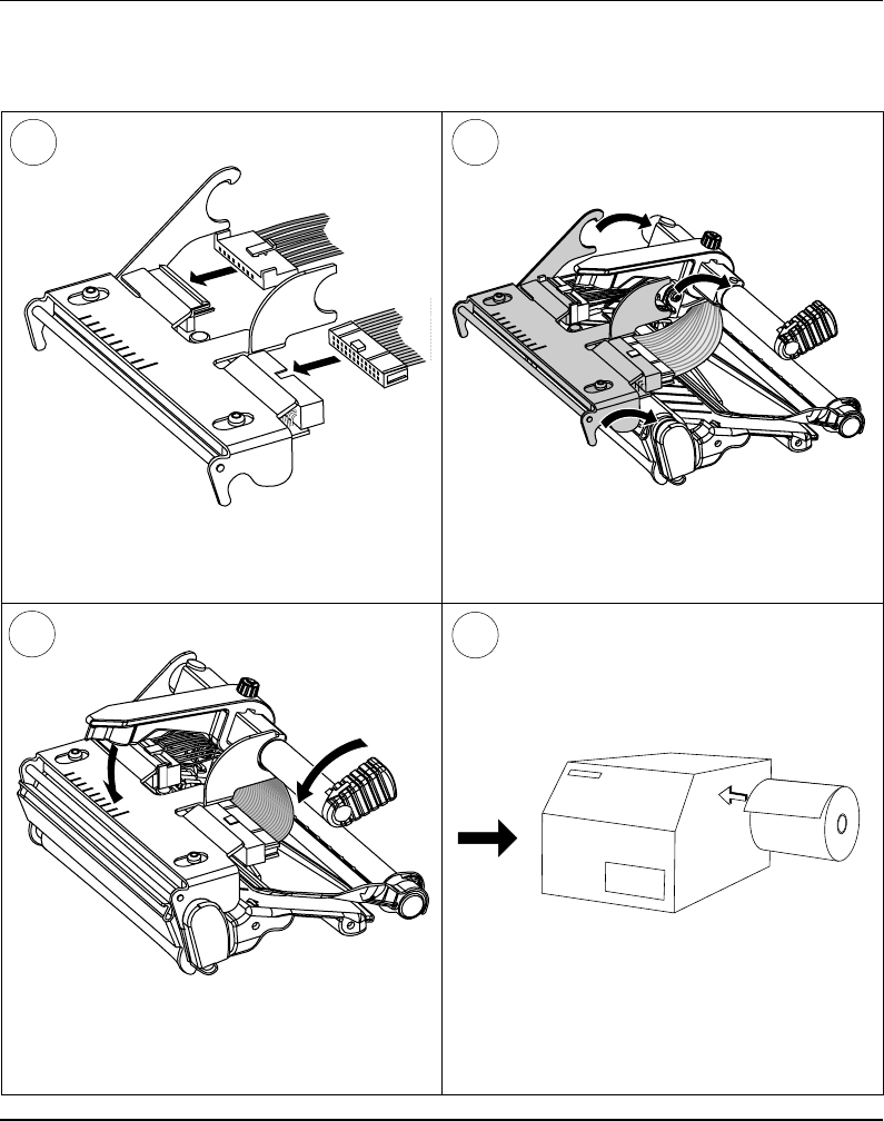
Disconnect the cables from the printhead. Note
the snap-lock on the inner connector. Pull at the
connectors – not the cables!
Remove the paper, if any.
Snap-lock
Intermec EasyCoder F4 – Installation & Operation Ed. 2 83
Chapter 11 Maintenance
Printhead Replacement, cont'd.
Connect the two cables to the replacement
printhead. Put back the printhead in reserse order and
check that the printhead cables run freely.
9
Load a new supply of paper as described ear-
lier in this manual.
Close the printhead so the magnet engages the
printhead bracket.
87
10
Intermec EasyCoder F4 – Installation & Operation Ed. 284
Chapter 12
Narrow Labels
Adjustment
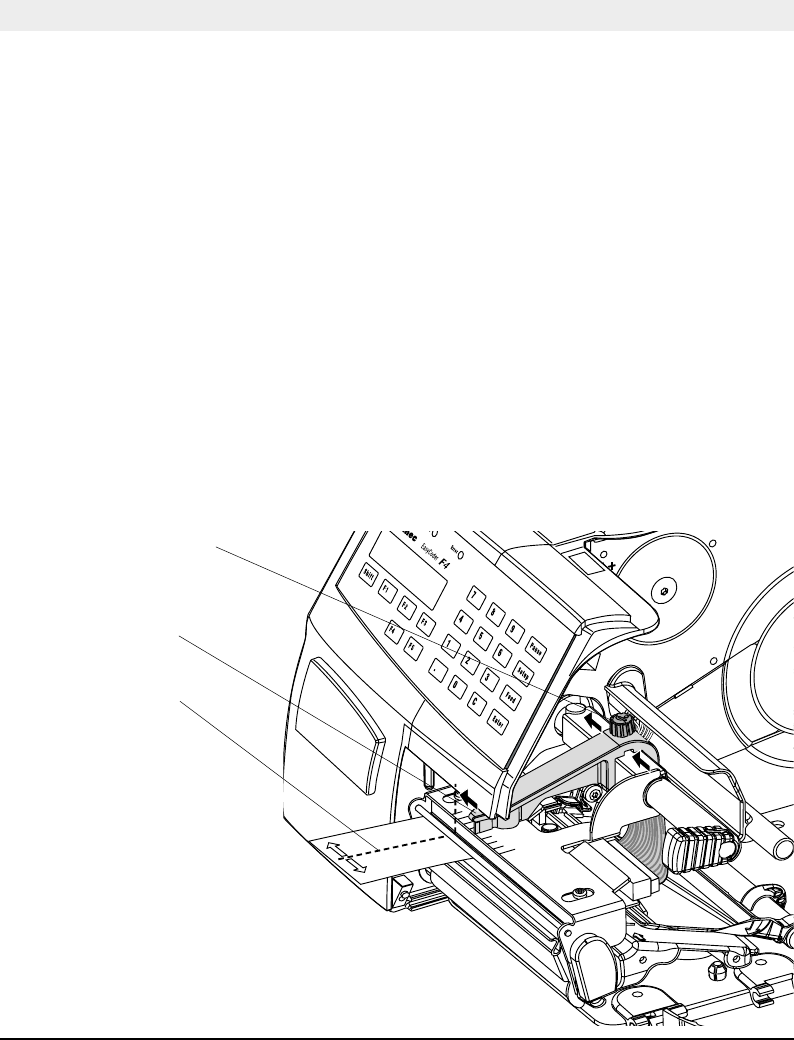
The printer is factory-adjusted for full size paper width. When using
paper less than full width, it is recommended to adjust the pressure
arm so it becomes centred on the paper. Thereby, an even pressure
across the paper is obtained.
A poorly adjusted pressure arm may be detected by a weaker printout
on the inner part of a less than full width paper. Similarly, when
reverting to a wider paper, the arm should be adjusted, or the printout
on the outer part of the paper could be weak.
To adjust the pressure arm, proceed as follows:
• Loosen the nut that holds the pressure arm. Move the arm inwards
or outwards until the arrow on the tip of the arm becomes
centre-aligned with the paper web.
While moving the arm, push at the part where the nut is situated,
not at the tip. If the arm is hard to move, lift the printhead and pull
the printhead bracket free from the magnet in the arm.
• After having centred the arm, lock it by tightening the nut.
Adjustments
Centre of Paper
Pressure Arm
Nut
Intermec EasyCoder F4 – Installation & Operation Ed. 2 85
Chapter 12 Adjustments
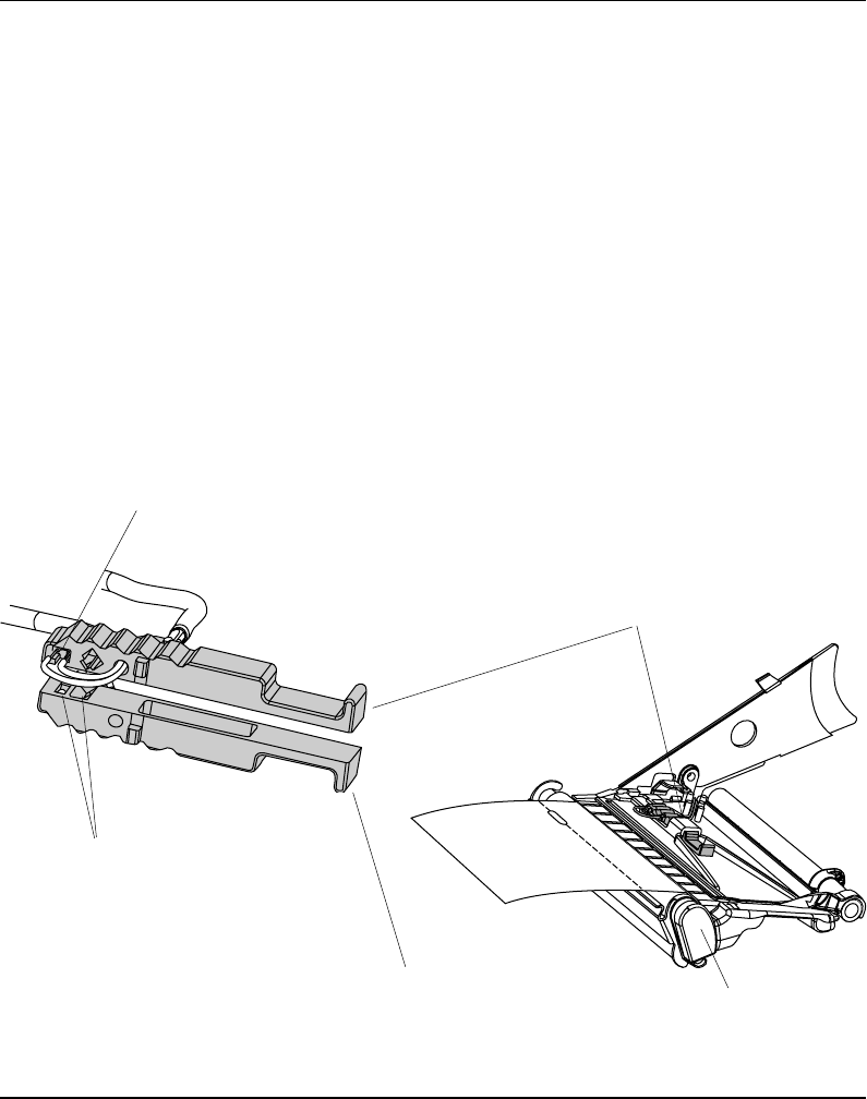
Label Stop Sensor
Position
The label stop/black mark sensor (LSS) is a photoelectric sensor that
controls the printer's paper feed by detecting gaps between labels,
slots in paper strip, or black marks, depending on the printer's setup
in regard of media type (see chapter 6 “Setting Up the Printer”).
A prerequisite is obviously that the LSS is aligned with the slots
or black marks.
Thus, the LSS can be moved laterally between 5 fi xed positions.
There is one sensor on top of the upper paper guide and underneath
the bottom of the print unit. These two guides must be set individually
to the same position. Push them inwards as far as they go and
then pull them out – one at the time – while counting the clicks
from the snap-locks.
The various detection points of the sensor in relation to the inner
edge of the paper are as follows:
One click out 3 mm .118"
Two clicks out 8 mm .315"
Three clicks out 12 mm .472"
Four clicks out 16 mm .639"
Five clicks out 20 mm .787"
If using irregularly shaped labels, align the LSS with the front
tips of the labels
Upper part of LSS
Print Unit
(printhead and headlift shaft omitted for
improved visibility)
One Diode + One Sensor
Lower part of LSS
One Sensor
Intermec EasyCoder F4 – Installation & Operation Ed. 286
Chapter 12 Adjustments
Printhead
Pressure
The pressure of the thermal printhead against the paper is factory
adjusted. However, the use of thicker or thinner paper than normal
could require the printhead pressure to be readjusted.
Using a fl at-tipped screwdriver, turn the adjustment screw clockwise
for increased pressure (+), or counter-clockwise for less pressure (-).
Print a few labels, preferably test labels (see chapter 6 “Setting Up
the Printer”), and check the printout. Increased pressure generally
gives a darker printout and vice versa. Repeat until the desired
result is obtained.
To return to the factory setting, tighten the screw (+) as far as it goes
and then loosen it (-) six (6) full turns.
Note!
Do not use a higher printhead pressure than necessary, because it
may increase the wear of the printhead and thus shorten its life.
Adjustment Screw

Intermec EasyCoder F4 – Installation & Operation Ed. 2 87
Appendix 1
Printing
Print Technique Direct Thermal
Printhead Resolution 8 dots/mm (203.2 dpi)
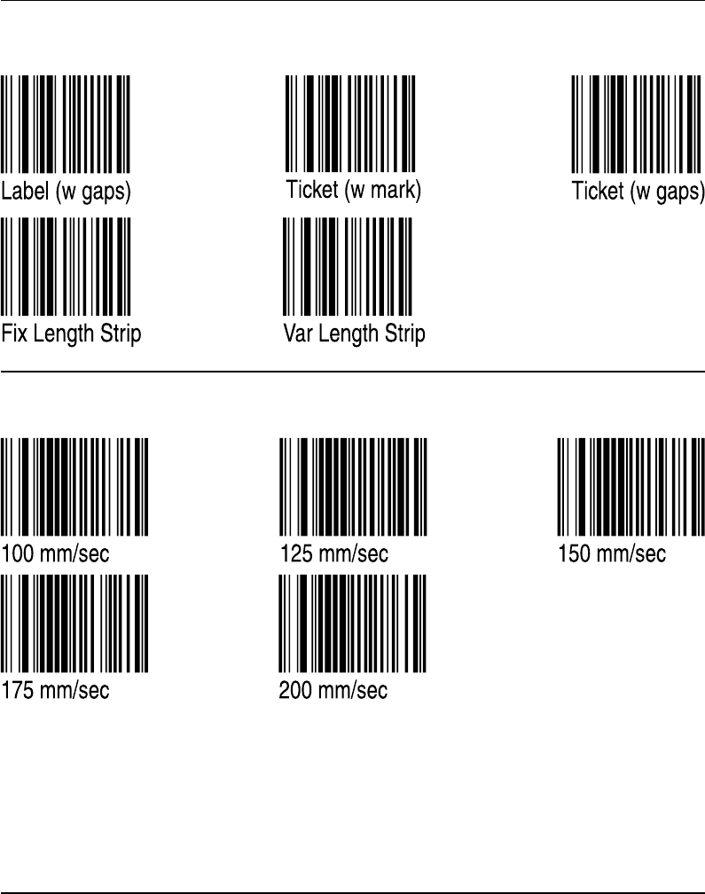
Print Speed (variable) 100 – 200 mm/sec. (≈ 4 – 8"/sec.)
Print Width (max) 104 mm (4.095") = 832 dots
Print Length (max) 32767 dots = 409.5 cm1
Media Width (min/max) 25 – 114.3 mm (1 –4.5") Standard paper guide
Media Width (min/max) 40 – 114.3 mm (1.57 – 4.5") Quick-Load guides
Paper Roll Diameter (max) 213 mm (8.38") Short door/no rewind
Paper Roll Core Diameter 38 – 40 mm (1.5") or 76 mm (3")
Print Directions 4
Modes of Operation
Tear Off Yes
Peel Off Optional Requires Rewind Unit
Firmware
Operating System Intermec Fingerprint 7.31 Incl. Direct Protocol
Smooth Fonts TrueDoc and TrueType fonts
Built-in scalable fonts (std) 15 Unicode fonts2
Built-in bar code symbologies (std) 36
Startup Program (std) Intermec Shell 4.4
Physical Measures
Dimensions (W x L x H) 244 x 397 x 178 mm (9.61 x 15.63 x 7.00") w. Long side door
Weight (excluding media) ≈ 7 kgs (15.5 lbs) Depending on model
Ambient Operating Temperature +5°C – +40° C (+41°F – +104° F)
Humidity 20 –80% non-condensing
Electronics
Microprocessor 32 bit RISC
On-board Flash SIMMs 1 – 2 Std. 1 x 2 Mbytes
On-board DRAM SIMM 1 Std. 4 Mbytes
Real-Time Clock Option 10+ years life
Power Supply
Mains Voltage >90 – <264 V AC, 45 – 65 Hz
PFC Regulation IEC 61000-3-2
Maximum Power Consumption Continuous 140 W; Peek 300W
Technical Data

Appendix 1 Technical Data
88 Intermec EasyCoder F4 – Installation & Operation Ed.2
Technical Data, cont’d.
Sensors
Label Gap/Black Mark/Out of Paper Yes 5 fixed positions
Printhead Lifted Yes
Controls
Control Lamps 3
Display 2 x 16 character LCD w. background light
Keyboard 22 keys membrane switch type
Print Button 1
Beeper Yes
Data Interfaces
Serial 1 x RS 232C + 1 x USB
Bar Code Wand Yes
Electronic Keys 2 For setup
Connection for Optional Interface Boards 1 Future option
Memory Card Adapter 1
Accessories and Options Flash or SRAM cards
RFID Module Option
Rewind Unit Option For peel-off operation
Paper Supply Spool Option Replaces hanger
3” Adapter for Paper Supply Spool Option
Short Side Door Option3
Long Side Door Option3
Label Taken Sensor Option
Real-Time Clock Option 10+ years life
Quick-Load Guides Standard Fitted in some models
RS 232C Cable Option
EasySet Bar Code Wand Option For quick setup
Parallel Interface Board Option IEEE 1284
Double Serial Interface Board Option
Industrial Interface Board Option
EasyLAN 100I Interface Board Option Ethernet
External Alphanumeric Keyboard Option
Flash Memory Cards Option
= 64 Mbit (8 MB)
Electronic Keys Option
1. The max. print length is also restricted by the amount of free DRAM memory.
2. Latin, Greek, and Cyrillic fonts according to Unicode standard are included.
3. Depending on model, the printer may be delivered with either a long or a short side door.

Intermec EasyCoder F4 – Installation & Operation Ed. 2 89
Appendix 2
Media Specifi cations
Direct Thermal
Labels
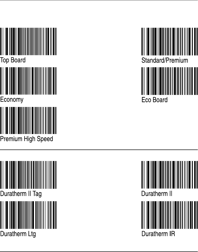
Intermec offers two quality grades of direct thermal paper for the
EasyCoder range of printers:
• Premium Quality: Top-coated papers with high demands on
printout quality and resistance against moisture, plasticisers and
vegetable oils. Examples...
- Top Board - Duratherm II,
- Premium - Duratherm II Tag
- Duratherm Ltg.
- Duratherm IR
• Economy Quality: Non top-coated papers with less resistance to
moisture, plasticisers and vegetable oils. In all other respects, it is
equal to Premium Quality. Examples...
- Economy
- Eco Board
Intermec EasyCoder F4 – Installation & Operation Ed. 290
Appendix 2 Media Specifi cations
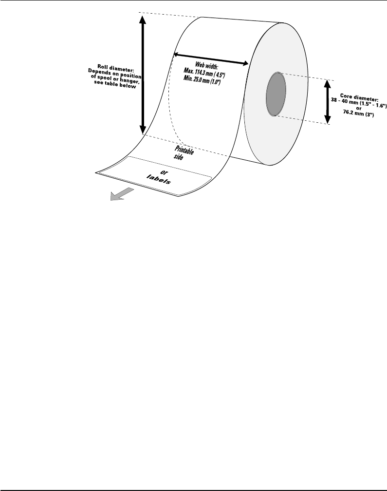
Paper Roll Size
Core
Diameters: 38 – 40 mm (1.5") or 76.2 mm (3")
Width: Must not protrude outside the web.
The web must be wound up on the core in such a way that the
printer can pull the end of the web free.
Roll
Max. diameter (internal supply only):
- Position 1 152 mm (6.00")
- Position 2 213 mm (8.38")
- Position 3 203 mm (8.00")
Max. width: 114.3 mm (4.50")
Min. width (standard): 25 mm (1.00")
Min. width (Quick-Load): 40 mm (1.57")
Max. web thickness: 175 µm (0.007")
The maximum recommended web thickness is 175µm. A thicker
web may be used, but print quality will be reduced. Web stiffness
is also important and must be balanced against web thickness to
maintain print quality.
Paper rolls fitted inside the printer should be wound with the
printable side facing outwards.
The paper supply must not be exposed to dust, sand, grit, etc. Any
hard particles, however small, can damage the printhead.
Intermec EasyCoder F4 – Installation & Operation Ed. 2 91
Appendix 2 Media Specifi cations
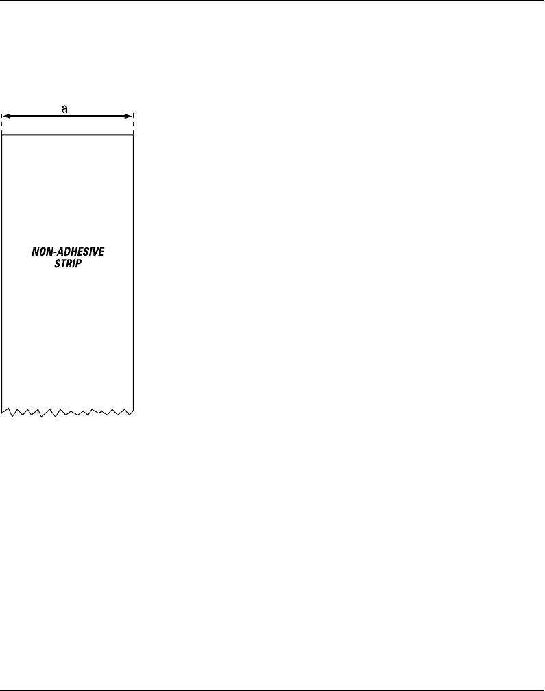
Non-Adhesive Strip
Paper
⇐ a ⇒ Web Width:
Maximum: 114.3 mm (4.50")
Minimum (standard): 25.0 mm (1.00")
Minimum (Quick-Load): 40.0 mm (1.57")
Media Type Setup:
• Fix length strip
• Var length strip
Intermec EasyCoder F4 – Installation & Operation Ed. 292
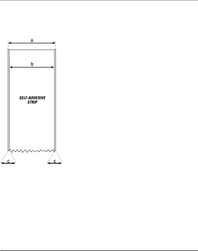
Appendix 2 Media Specifi cations
⇐ a ⇒ Web Width (including backing paper):
Maximum: 114.3 mm (4.50")
Minimum (standard): 25.0 mm (1.00")
Minimum (Quick-Load): 40.0 mm (1.57")
⇐ b ⇒ Backing Paper
The backing paper must not extend more than a total of 1.6 mm
(0.06") outside the paper and should protrude equally on both
sides.
⇐ c ⇒ Paper Width (excluding backing paper):
Maximum: 112.74 mm (4.43")
Minimum: 23.8 mm (0.94")
Media Type Setup:
• Fix length strip
• Var length strip
Self-Adhesive Strip
Paper, cont'd.
Intermec EasyCoder F4 – Installation & Operation Ed. 2 93
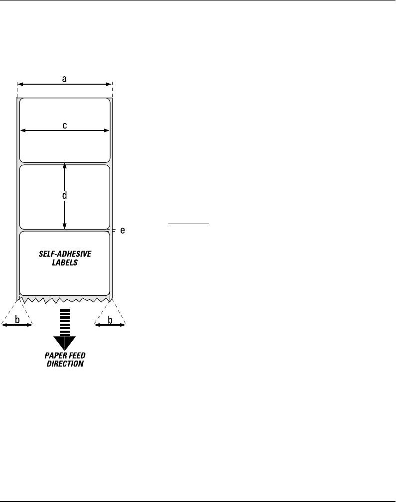
Appendix 2 Media Specifi cations
⇐ a ⇒ Web Width (including backing paper):
Maximum: 114.3 mm (4.50")
Minimum (standard): 25.0 mm (1.00")
Minimum (Quick-Load): 40.0 mm (1.57")
⇐ b ⇒ Backing Paper
The backing paper must not extend more than a total of 1.6 mm
(0.06") outside the paper and should protrude equally on both side.
Recommended min. transparency: 40% (DIN 53147).
⇐ c ⇒ Label Width (excluding backing paper):
Maximum: 112.7 mm (4.43")
Minimum: 23.8 mm (0.94")
⇐ d ⇒ Label Length:
Minimum: 8.0 mm (0.32")
Max label length: depends on DRAM size
Under favourable circumstances, a minimum label length down to
4 mm (0.16") could be used. It requires the sum of the label length
(d) and the label gap (e) to be larger than 7 mm (0.28"), that batch
printing is used, and that no pull back of the paper is performed.
Intermec does not guarantee that such short labels will work, but it
is up to the user to test this in his unique application.
⇐ e ⇒ Label Gap:
Maximum: 21.3 mm (0.83")
Recommended: 3.0 mm (0.12")
Minimum: 1.2 mm (0.05")
The Label Stop Sensor must be able to detect the extreme front
edges of the labels. It can be moved between 5 fi xed positions at the
following distances from the inner edge of the paper.
3 mm (.118")
8 mm (.315")
12 mm (.472")
16 mm (.639")
20 mm (.787")
Media Type Setup:
• Label (w gaps)
Self-Adhesive Labels
Paper, cont'd.
Intermec EasyCoder F4 – Installation & Operation Ed. 294
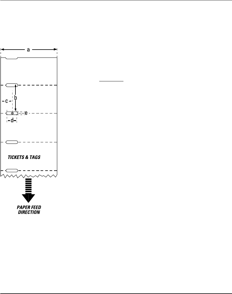
Appendix 2 Media Specifi cations
Paper, cont'd.
Tickets with Gap
⇐ a ⇒ Web Width:
Maximum: 114.3 mm (4.50")
Minimum (standard): 25.0 mm (1.00")
Minimum (Quick-Load): 40.0 mm (1.57")
⇐ b ⇒ Copy Length:
Min. length between slots: 8.0 mm (0.32")
Max. length between slots: depends on DRAM size
Under favourable circumstances, a minimum ticket length down
to 4 mm (0.16") could be used. It requires the sum of the copy
length (b) and the detection slit height (e) to be larger than 7
mm (0.28"), that batch printing is used, and that no pull back of
the paper is performed. Intermec does not guarantee that such
short labels will work, but it is up to the user to test this in his
unique application.
⇐ c ⇒ LSS Detection Position:
Five fi xed positions (distance from inner edge of paper):
3 mm (.118")
8 mm (.315")
12 mm (.472")
16 mm (.639")
20 mm (.787")
⇐ d ⇒ Detection Slit Length:
The length of the detection slit (excluding corner radii) must be
minimum 2.5 mm (0.10") on either side of the LSS detection
position (e).
⇐ e ⇒ Detection Slit Height:
Maximum: 21.3 mm (0.83")
Recommended: 1.6 mm (0.06")
Minimum: 1.2 mm (0.05")
Media Type Setup:
• Ticket (w gaps)
Do not allow any perforation to break the edge of the web, as this
may cause the web to split, resulting in a paper jam.
Intermec EasyCoder F4 – Installation & Operation Ed. 2 95
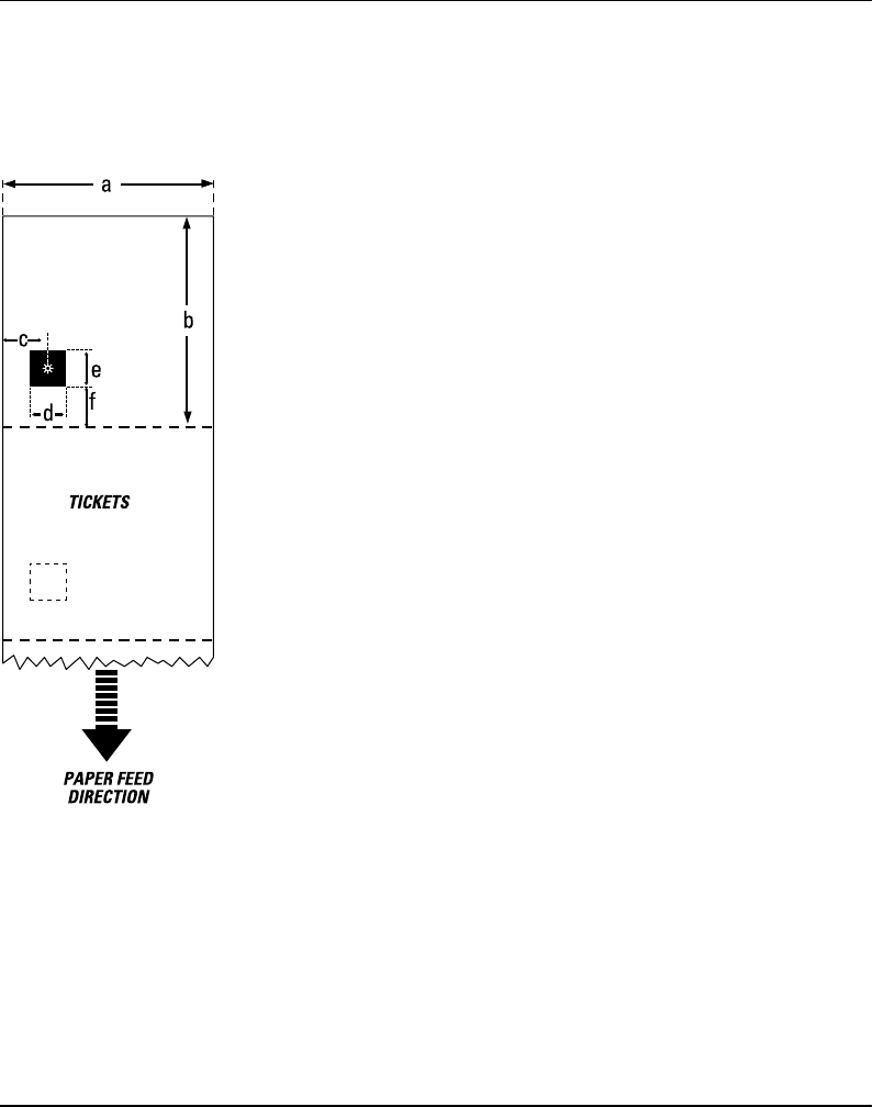
Appendix 2 Media Specifi cations
Paper, cont'd.
Tickets with Black Mark
⇐ a ⇒ Web Width:
Maximum: 114.3 mm (4.50")
Minimum (standard): 25.0 mm (1.00")
Minimum (Quick-Load): 40.0 mm (1.57")
⇐ b ⇒ Copy Length:
Minimum: 20.0 mm (0.8")
Maximum: depends on DRAM size
⇐ c ⇒ LSS Detection Position:
Five fi xed positions (distance from inner edge of paper):
3 mm (.118")
8 mm (.315")
12 mm (.472")
16 mm (.639")
20 mm (.787")
⇐ d ⇒ Black Mark Width:
The detectable width of the black mark should preferably be at least
5.0 mm (0.2") on either side of the LSS detection point.
⇐ e ⇒ Black Mark Length:
Maximum: 21.3 mm (0.83")
Common: 12.5 mm (0.5")
Minimum: 5.0 mm (0.2")
⇐ f ⇒ Black Mark Y-Position:
It is recommended to place the black mark as close to the front
edge of the ticket as possible and use a negative Stop Adjust
value to control the paper feed, so the tickets can be properly
torn or cut off.
Media Type Setup:
• Ticket (w mark)
Important! Preprint that may interfere with the detection of the
black mark should be avoided on the back of the paper. However,
the LBLCOND statement allows the sensor to be temporarily
disabled during a specifi ed amount of paper feed in order to avoid
unintentional detection, see Intermec Fingerprint manuals.
The black mark should be non-refl ective carbon black on a whitish
background.
Do not allow any perforations to break the edge of the web, as this
may cause the web to split, resulting in a paper jam.
Intermec EasyCoder F4 – Installation & Operation Ed. 296
Appendix 3
Interfaces
RS 232C Interface
"uart1:"
The EasyCoder F4 has – as standard – two serial communication
interfaces: RS 232C on "uart1:" and USB (see next page).
Protocol
Default setup:
Baudrate: 9600
Char. length 8 bits
Parity: None
Stop bits: 1
RTS/CTS Disabled
ENQ/ACK: Disabled
XON/XOFF: Disabled (both ways)
New Line: CR/LF
To change the serial interface settings, see chapter 6 “Setting
Up the Printer”.
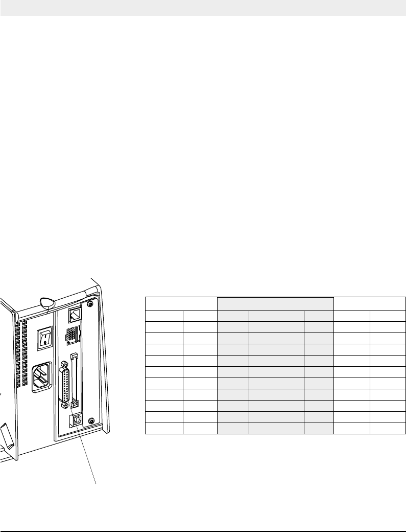
Interface Cable
Computer end: DB-9 or DB-25 female connector (PC)
Printer end: DB-25 male connector
Host EasyCoder F4 Host
Signal DB-9 DB-25 Signal DB-25 DB-25 Signal
1 1 1 1 shield
RXD 2 2 TXD 2 3 RXD
TXD 3 3 RXD 3 2 TXD
CTS 8 4 RTS 4 5 CTS
RTS 7 5 CTS 5 4 RTS
6 DSR 6 20 DTR
GND 5 7 Signal GND 7 7 GND
16 + 5V1 16
DSR 6 20 DTR 20 6 DSR
22 RI 22
1/. The external +5V is limited to 200 mA and is automatically turned
off at overload. It is intended to drive e.g. an external alphanumeric
keyboard connected to the RS 232C port.
Intermec EasyCoder F4 – Installation & Operation Ed. 2 97
Appendix 3 Interfaces
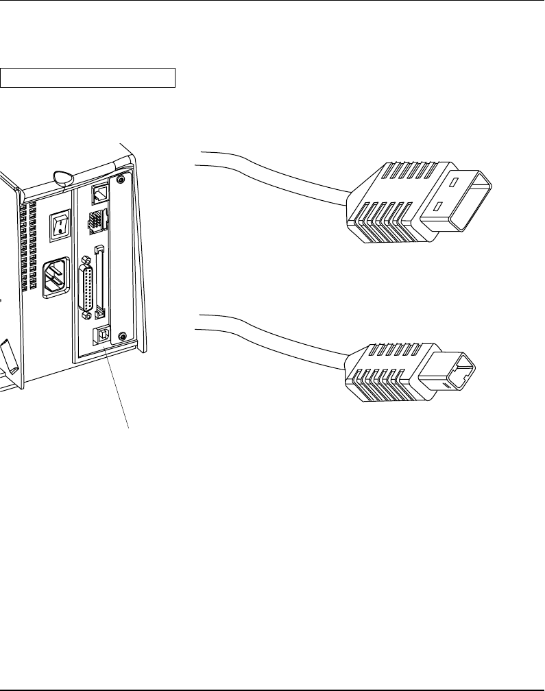
USB Interface
The EasyCoder F4 has – as standard – one USB communication
port. To use the USB interface for printing from a PC, you need a
special USB printer driver installed in your PC.
Using an USB Class A - B cable, connect the Class A end to your PC
or hub and the Class B end to your EasyCoder F4 printer.
USB = Universal Serial Bus
USB Class A connector.
Connect to PC or hub.
USB Class B connector.
Connect to USB receptacle on the printer's rear plate.
Note:
The USB interface is presently not supported by the Intermec
Fingerprint fi rmware (v. 7.31).
USB

Intermec EasyCoder F4 – Installation & Operation Ed. 298
Appendix 3 Interfaces
The EasyCoder F4 can optionally be fi tted with an extra double
serial interface board, which provides the printer with two more
serial ports; "uart2:" and "uart3:". These ports can be confi gured
for various types of serial communication in combination according
to the customer's request. Use the Intermec Fingerprint instruction
SETSTDIO to select standard IN and OUT ports (by default "uart1:"
is both std IN and OUT port)1.
"uart2:" "uart3:"
RS 232C RS 232C
RS 422 Non-isolated RS 422 Non-isolated
RS 422 Isolated 20 mA Current Loop
RS 485
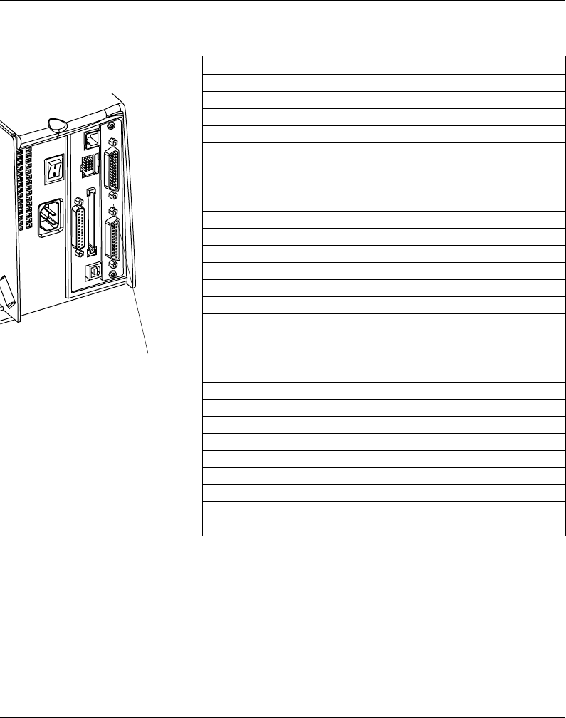
"uart2:" Serial Port
The communication ports "uart2:" uses a female DB 25 connector.
Pin Signal Name Description
1 Not connected
2 TxD RS 232 Transmitter
3 RxD RS 232 Receiver
4 RTS RS 232 Request To Send
5 CTS RS 232 Clear To Send
6 DSR RS 232 Data Set Ready
7 GND Ground
8–14 Not connected
15 +RS422I +RS 422 Receive
16 +5V 5 Volt for external use (max. 200 mA)1
17 -RS422I -RS 422 Receive
18 Not connected
19 +RS422O/+RS485 +RS 422 Transmit/+RS 485
20 DTR RS 232 Data Terminal Ready
21 -RS422O/-RS485 -RS 422 Transmit/-RS 485
22 RI RS 232 Ring Indicator
23 Shield Optional shield for RS 422 and RS 485
24–25 Not connected
1/. The external 5V is automatically turned off at overload.
Double Serial
Interface Board
"uart2:"
1/. Intermec Shell either auto-
matically sets the correct std IN
and OUT port when an applica-
tion is selected, e.g. a Windows
driver, or prompts you to select
one, see chapter 8.
Intermec EasyCoder F4 – Installation & Operation Ed. 2 99
Appendix 3 Interfaces
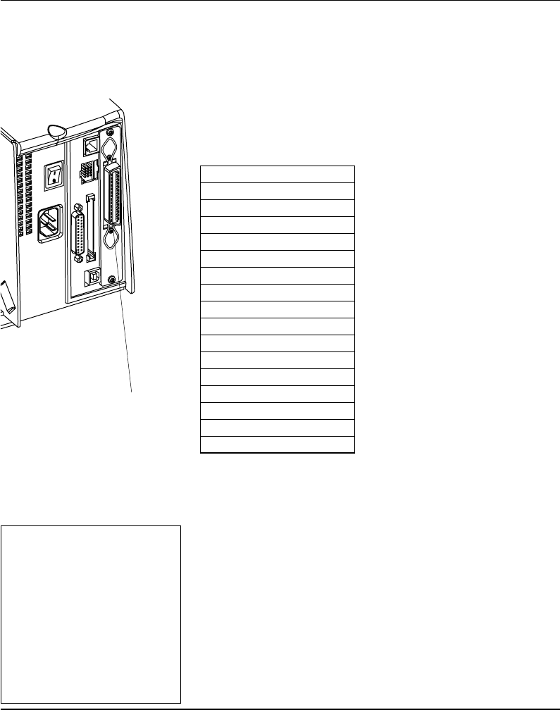
"uart3:" Serial Port
The communication ports "uart3:" uses a male DB 25 connector.
Pin Signal Name Description
1 Not connected
2 TxD RS 232 Transmitter
3 RxD RS 232 Receiver
4 RTS RS 232 Request To Send
5 CTS RS 232 Clear To Send
6 DSR RS 232 Data Set Ready
7 GND Ground
8 Not connected
9 +20M1 +20 mA current loop
10 -20M1 -20 mA current loop
11 +TXD +TXD 20 mA current loop
12 -TXD -TXD 20 mA current loop
13 +20M2 +20 mA current loop
(printer active receiver)
14 -20M2 -20 mA current loop
(printer active receiver)
15 +RS422I +RS 422 Receive
16 +5V 5 Volt for external use (max. 200 mA)1
17 -RS422I -RS 422 Receive
18 +RxD +TXD 20 mA current loop
19 +RS422O/+RS485 +RS 422 Transmit/+RS 485
20 DTR RS 232 Data Terminal Ready
21 -RS422O/-RS485 -RS 422 Transmit/-RS 485
22 RI RS 232 Ring Indicator
23 Shield Optional shield for RS 422 and RS 485
24 Not connected
25 -RxD -TXD 20 mA current loop
1/. The external 5V is automatically turned off at overload.
Double Serial
Interface Board,
cont'd.
"uart3:"
Intermec EasyCoder F4 – Installation & Operation Ed. 2100
Appendix 3 Interfaces
1/. Nibble, byte, ECP and EPP
from printer to host are presently
not supported.
2/. Intermec Shell either auto-
matically sets the correct std IN
and OUT port when an applica-
tion is selected, e.g. a Windows
driver, or prompts you to select
one, see chapter 8.
IEEE 1284
Parallel Interface
Board
The EasyCoder F4 can optionally be fi tted with an IEEE 1284-I
compatible parallel interface board1. The parallel port is addressed
in Intermec Fingerprint as device "centronics:". Select "centronics:"
as standard IN port by means of the instruction SETSTDIO (by
default, "uart1:" in std IN port)2.
Interface Cable Connectors
Computer end: Depends on type of host computer.
Printer end: 36 pin female IEEE 1284B Centron
Pin Signal Name
1 DStrobe
2–9 Data 0–7
10 Ack
11 Busy
12 PE
13 Select
14 AF
15 Not connected
16 Ground
17 Screen
18 +5V Ext
19 –30 GND
31 Init
32 Error
33-35 Not connected
36 Selectin
"centronics:"
Intermec EasyCoder F4 – Installation & Operation Ed. 2 101
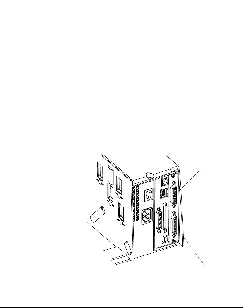
Appendix 3 Interfaces
Industrial
Interface Board
The EasyCoder F4 can optionally be fitted with an Industrial
Interface Board, that provides the printer with one extra serial
communication port ("uart2:"), which can be confi gured for one
of the following alternatives
RS 232C
RS 422 Non-isolated
RS 422 Isolated
RS 485
This port is identical to "uart2:" on the double serial interface
board.
The Industrial Interface Board also has a female DB-44 connector
with...
8 digital IN ports with optocouplers
8 digital OUT ports with optocouplers
4 OUT ports with relays.
Refer to the installation instructions for the Industrial Interface
Board for further information.
"uart2:"
Industrial Interface
Intermec EasyCoder F4 – Installation & Operation Ed. 2102
Appendix 3 Interfaces
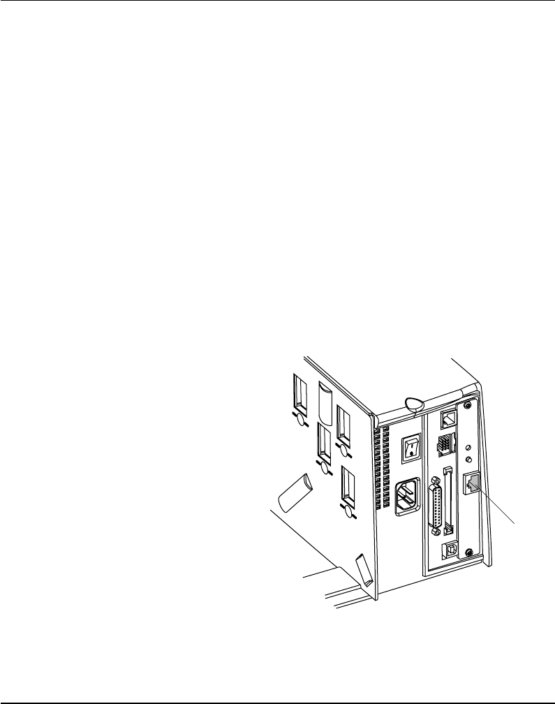
The Intermec EasyLAN 100i Ethernet interface board provides
the printer with a 10BaseT Ethernet or 100BaseTX Fast Ethernet
network connection. You can communicate with the printer via
a LAN (Local Area Network) or provide the printer with its own
home page, so you can reach the printer via internet on the world
wide web (www).
EasyLAN 100i supports most major computer systems and environ-
ments. You can assign passwords to restrict both login and printer
access. The internal EasyLAN 100i web pages allow you to con-
tinuously monitor printer status and to upgrade the fl ash memory of
the printer when new fi rmware becomes available.
EasyLAN 100i supports SNMP for remote monitoring.
When an EasyLAN 100i interface board is fi tted in the printer, some
extra menus will be added to the Setup Mode (see chapter 7 “Setup
Mode”). The Ethernet port is addressed in Intermec Fingerprint 7.3
or later as device "net1:" (communication channel 5).
EasyLAN 100i
Interface Board
RJ-45
connector
Intermec EasyCoder F4 – Installation & Operation Ed. 2 103
Appendix 4
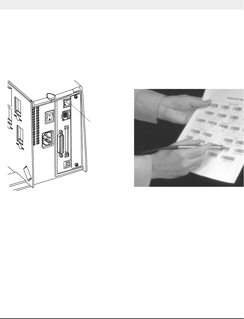
EasySet Bar Code Wand Setup
1. Connect the optional EasySet bar code wand to
the receptacle on the printer’s rear plate.
3. When the bar code has been accepted, the printer
emits a short beep and the Ready control lamp
on the printer’s front blinks briefl y.
2. Read the appropriate bar code to set up the
printer. Hold the wand like a pencil and move it
rather swiftly across the bar code.
4. This manual only contains a selection of setup
options. For information on how to produce your
own setup bar codes, please refer to the Intermec
Fingerprint 7.31 Reference Manual.
Connect
here!
Connection and Operation
Intermec EasyCoder F4 – Installation & Operation Ed. 2104
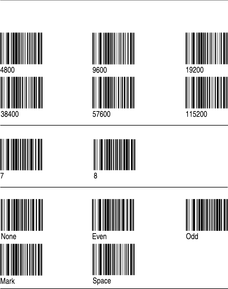
Appendix 4 EasySet Bar Code Wand Setup
Serial Communication on "uart1:"
Baudrate
Parity
Char. Length
Intermec EasyCoder F4 – Installation & Operation Ed. 2 105
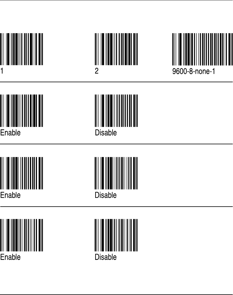
Appendix 4 EasySet Bar Code Wand Setup
Serial Communication on "uart1:", cont'd.
No. of Stop Bits
RTS/CTS
XON/XOFF, Data to Host
Reset comm. to default
ENQ/ACK
Intermec EasyCoder F4 – Installation & Operation Ed. 2106
Appendix 4 EasySet Bar Code Wand Setup
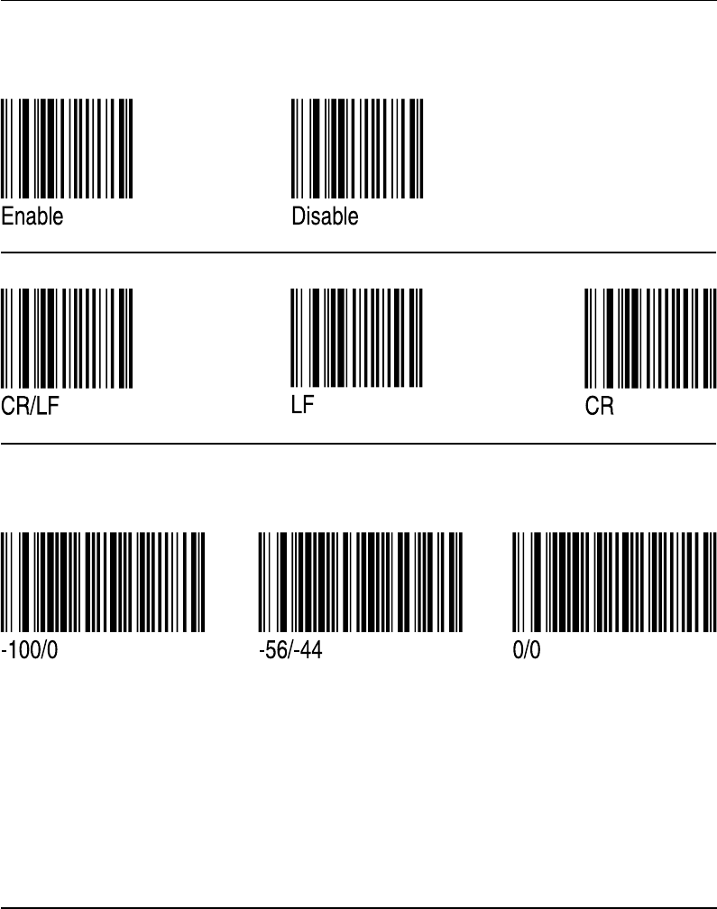
Start- and Stopadjust
Peel Off
Tear Off
XON/XOFF, Data from Host
New Line
Serial Communication on ”uart1:”, cont’d.
Default
Intermec EasyCoder F4 – Installation & Operation Ed. 2 107
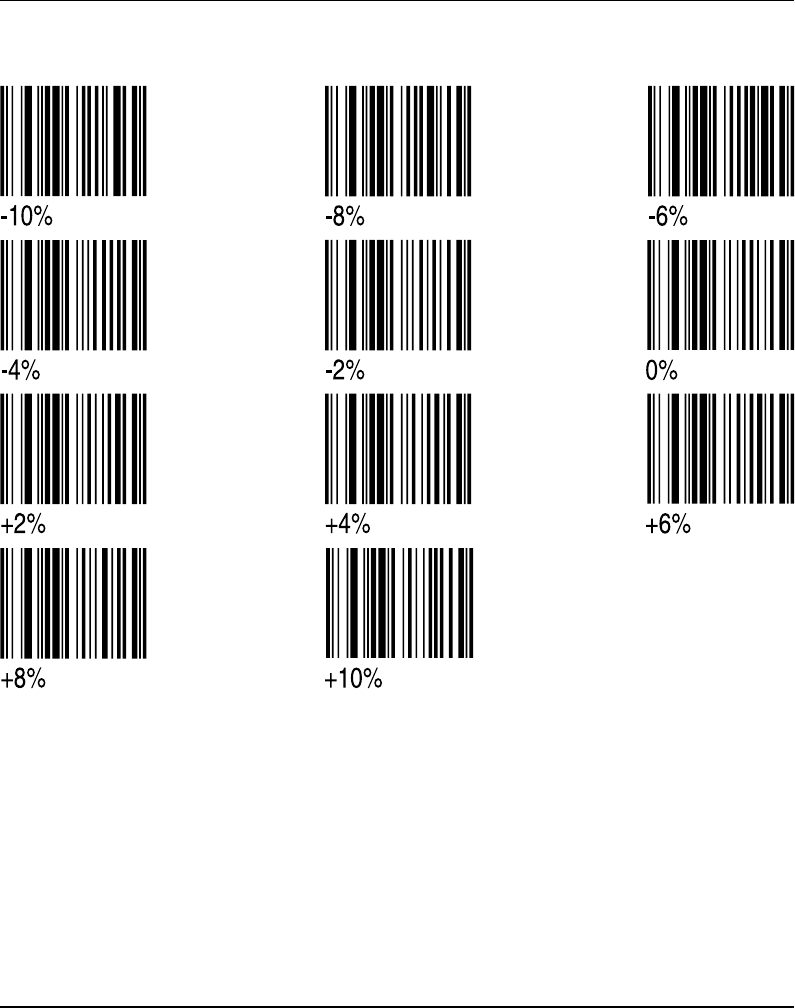
Appendix 4 EasySet Bar Code Wand Setup
Contrast
Intermec EasyCoder F4 – Installation & Operation Ed. 2108
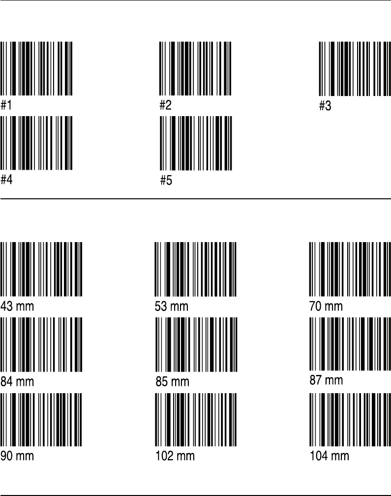
Appendix 4 EasySet Bar Code Wand Setup
Media Width
Test Labels
Intermec EasyCoder F4 – Installation & Operation Ed. 2 109
Appendix 4 EasySet Bar Code Wand Setup
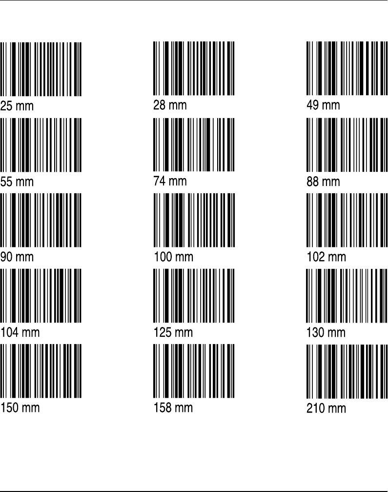
Media Length
Intermec EasyCoder F4 – Installation & Operation Ed. 2110
Appendix 4 EasySet Bar Code Wand Setup
Print Speed
Media Type
Intermec EasyCoder F4 – Installation & Operation Ed. 2 111
Appendix 4 EasySet Bar Code Wand Setup
Direct Thermal Printing (Europe)
Paper Type
Direct Thermal Printing (USA)
Intermec EasyCoder F4 – Installation & Operation Ed. 2
Appendix 5 RFID Module
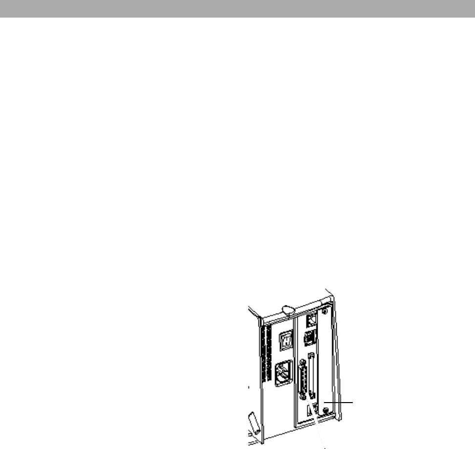
RFID Module
The EasyCoder F4 can optionally be fitted with an Intellitag® 500 RFID (radio
frequency identification) board that provides the printer with the means to pre-
program Intellitag® 500 RFID SmartLabels when the bar code portion of the label is
printed.
The RFID board is addressed in Intermec Fingerprint 7.3 or later as device “uart2:”
The RFID board does not require connection to any device external to the printer.
The RFID module is fitted in the printer in the space allocated for optional interface
boards and therefore cannot be used in conjuction with, or in addition to, any of the
optional interface boards.
Refer to the installation instructions for the RFID Option Board for further
information.
Chassis location for RFID module
112

113Intermec EasyCoder F4 – Installation & Operation Ed. 2
Notes