TransCore F4-06476-LP RFID Bar Code Printer User Manual Part 2
TransCore RFID Bar Code Printer Part 2
Contents
- 1. User manual Part 1
- 2. User manual Part 2
- 3. User manual Part 3
- 4. User Manual Update
User manual Part 2
Intermec EasyCoder F4 – Installation & Operation Ed. 2 37
Chapter 5 Paper Load
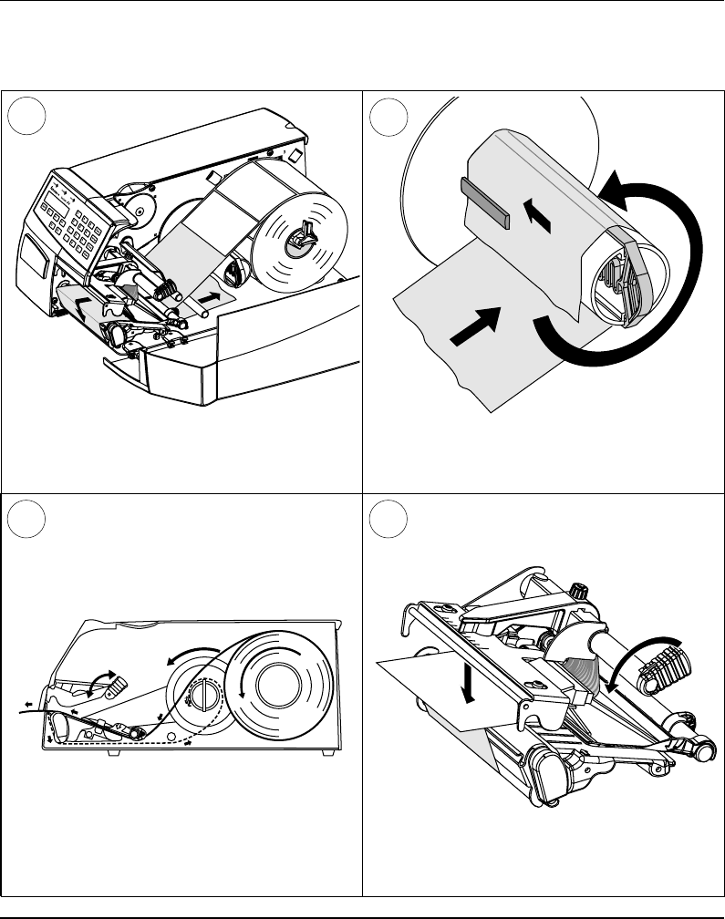
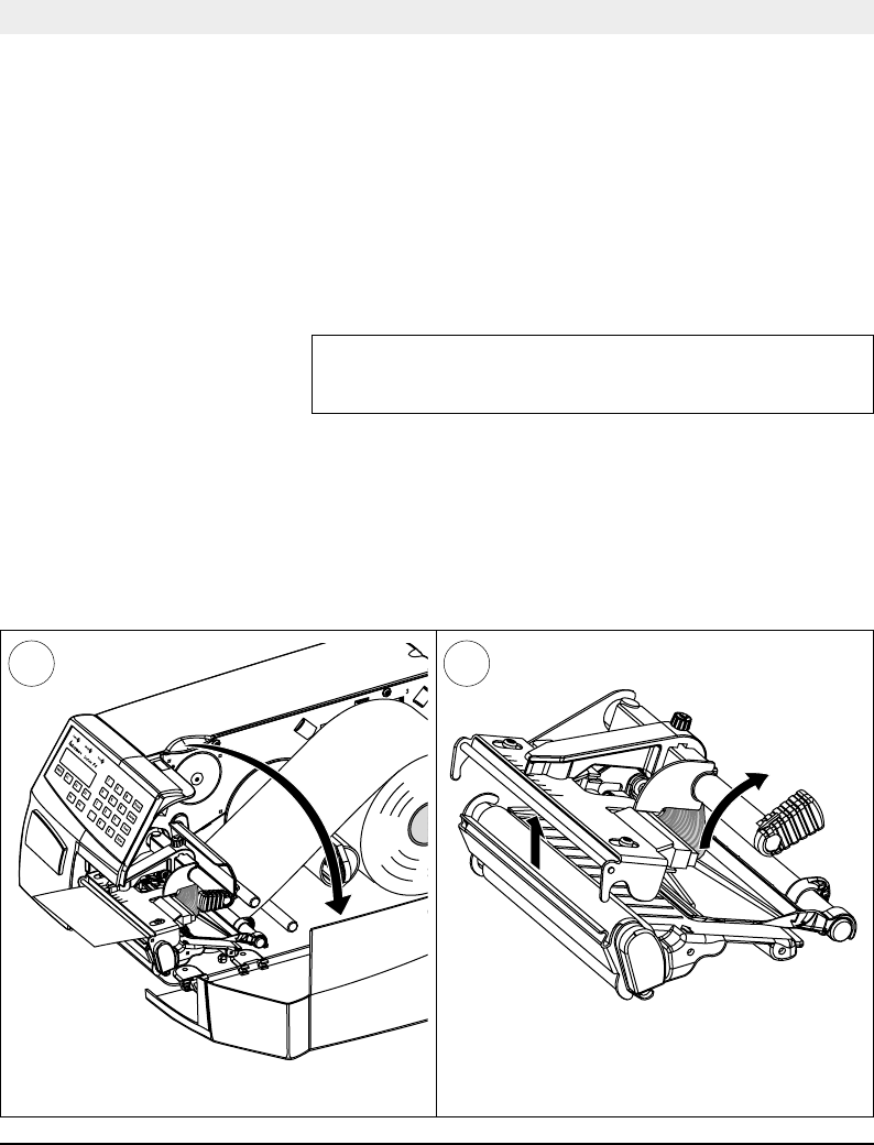
Peel-Off, cont'd.
Thread the backing paper around the tear-off
edge and back under the print mechanism and
guide shaft.
Insert the end of the backing paper under the
lip of the rewinder, then rotate the rewinder
counter-clockwise a few turns.
78
This diagram shows the path of the label web.
9 10
Turn the printhead lift knob counter-clockwise
to lower the printhead
Intermec EasyCoder F4 – Installation & Operation Ed. 238
Chapter 5 Paper Load
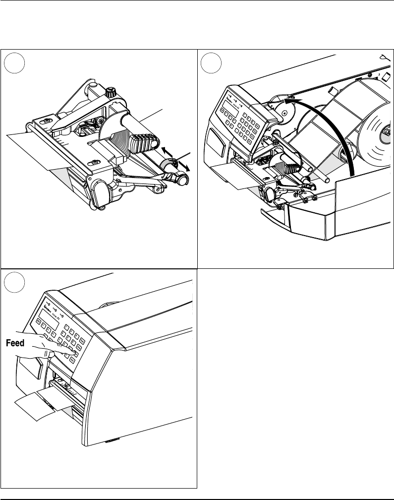
Peel-Off, cont'd.
Adjust the position of the green paper guide so
the paper is guided with a minimum of play.
11 12
Close the side door.
13
Adjust the paper feed by pressing the Feed
key.
Intermec EasyCoder F4 – Installation & Operation Ed. 2 39
Chapter 5 Paper Load
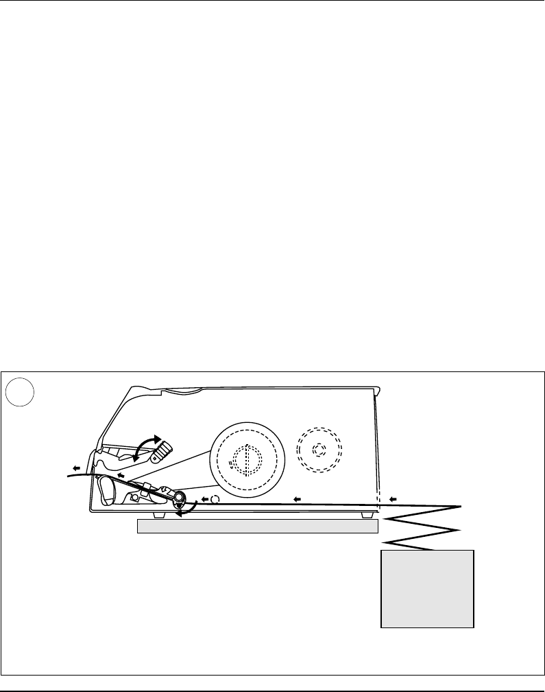
External Supply
This diagram shows the path of the paper web from an external supply. In case of the standard
paper guide ring, it is recommended to turn it to vertical position for better guiding of the web.
The EasyCoder F4 can print on labels, tickets, tags, and paper strip
in various forms. This chapter describes the case the paper supply is
placed behind the printer, usually in the form of fan-folded tickets
and tags. External supply can be used in connection with tear-off
operation – preferably with Quick-Load.
External supply can be used with both short and long side doors and
there is no need to remove the paper roll hanger.
When using an external paper supply, take care to protect the paper
from dust, dirt or other foreign particles, that can impair the printout
quality or cause unnecessary wear to the printhead.
Direct thermal paper is more or less sensitive to heat, direct sunlight,
moisture, oil, plasticizers, fat, and other substances, depending on
brand and quality and should be protected accordingly.
1

Intermec EasyCoder F4 – Installation & Operation Ed. 240
Chapter 6
Setting Up the Printer
Description
The setup is used to control the printer in regard of serial com-
munication, paper feed and print speed, and to specify which type
of paper is loaded in the printer.
Check the list of default setup values below to see if the printer's
setup matches your requirements. If not, you will have to change
the setup, which can be done manually via the printer's built-in
keyboard, remotely from the host computer, or by reading a bar
code containing setup data with the optional EasySet bar code
wand. The setup may also be changed, partially or completely, by
certain application programs.
• In the Setup Mode:
- Press the < Setup> key on the printer's built-in keyboard
to enter the Setup Mode.
- Select the Setup option in Intermec Shell to enter the
Setup Mode.
- Execute the Intermec Fingerprint SETUP instruction to
enter the Setup Mode.
See chapter 7 “Setup Mode” in this manual.
• In Intermec Shell:
- Use Terminal Setup option to change the setup remotely
from the host.
Note that Intermec Shell automatically sets up the printer in regard
of communication when an application is selected.
See chapter 8 “Intermec Shell” in this manual.
• In Intermec Fingerprint:
- Use Setup strings to change individual setup parameters
remotely from the host.
- Use Setup fi les to create sets of setup parameters remotely
from the host.
See SETUP statement in the Intermec Fingerprint 7.xx Reference
Manual.
• In the Intermec Direct Protocol:
- Use Setup strings to change individual setup parameters
remotely from the host.
See Intermec Direct Protocol 7.xx Programmer's Guide.
• Using the EasySet Bar Code Wand:
- Read a Code 128 bar code containing the setup parameter id.
and the desired value or choice. See Appendix 4.

Intermec EasyCoder F4 – Installation & Operation Ed. 2 41
Chapter 6 Setting Up the Printer
Default Setup
The printer is by default set up according to the list below:
Ser-Com "uart1:"
Baudrate: 9600 bps
Character length: 8 bits
Parity: None
Stop bits: 1 bit
RTS/CTS: Disable
ENQ/ACK: Disable
XON/XOFF, data to host: Disable
XON/XOFF, data from host: Disable
New line: CR/LF
Receive buffer: 300 bytes
Transmit buffer: 300 bytes
Feedadjust:
Startadjust: 0
Stopadjust: 0
Media:
X-start: 24
Width: 832
Length: 1200
Media Type: Label (w Gaps)
Label Constant: 85
Label Factor: 40
Contrast: ±0%
Print Defi nes:
Print speed: 100 mm/sec.
The printer's current setup values can be read from the display by
browsing through the Setup Mode, or from the host by browsing
through the Terminal Setup of Intermec Shell.
You can list the printer's current setup values by printing test label
#5 in the Setup Mode or using Intermec Shell.
The current setup values can be returned to the host by means of a
SETUP WRITE "uart1:" statement (see Intermec Fingerprint
7.xx Reference Manual).

Intermec EasyCoder F4 – Installation & Operation Ed. 242
Chapter 6 Setting Up the Printer
Setup Parameters
Serial Communication
• Baudrate
• Character Length
• Parity
• Stop Bits
• Flow Control
• New Line
• Receive Buffer
• Transmit Buffer
The serial communication setup controls the communication
between the printer and the connected computer or other devices
on the standard serial channel "uart1:" and the optional serial
channels "uart2:" and "uart3:". The latter channels require an
optional interface board to be fi tted. The printer's fi rmware detects
if an optional interface board is fi tted and presents additional sets of
communication setup menus depending on type of communication
(refer to diagrams #3 – 5 in chapter 7 “Setup Mode”).
The serial communication setup has no consequence whatsoever
for parallel communication or for the IN and OUT ports on the
optional Industrial Interface Board.
For the serial communication channel "uart1", the following
parameters can be set. Make sure they match the setup of the
connected device or vice versa. If the setup of the printer and the
setup of the host do not match, the response from the printer to
host will be garbled.
Baudrate
The baudrate is the transmission speed in bits per second. There
are 10 options:
• 300
• 600
• 1200
• 2400
• 4800
• 9600 (default)
• 19200
• 38400
• 57600
• 115200

Intermec EasyCoder F4 – Installation & Operation Ed. 2 43
Chapter 6 Setting Up the Printer
Setup Parameters, cont'd.
Serial Communication,
cont'd. Character Length
The character length specifi es the number of bits in a character.
For most purposes 7 bits will be suffi cient, but if special characters
or characters specifi c for other languages are to be used, 8 bits are
recommended. Refer to the Intermec Fingerprint 7.xx Reference
Manual for information on which characters are available in various
combinations of character length and character set.
• 7 Characters ASCII 0 – 127 decimal
• 8 Characters ASCII 0 – 255 decimal (default)
Parity
The parity decides how the fi rmware will check for transmission
errors. There are fi ve options:
• None (default)
• Even
• Odd
• Mark
• Space
Stop Bits
The number of stop bits specifi es how many bits will defi ne the end
of a character. There are two options:
• 1 (default)
• 2
Flow Control
• RTS/CTS
RTS/CTS is a protocol where the communication is controlled by
currents through separate lines in the cable being set either to high
or low. By default, this option is disabled.
RTS high indicates that the transmitting unit is able to receive
characters. RTS low indicates that the receive buffer is fi lled
to 75% (see XON/XOFF).
CTS high indicates that the unit transmitting the CTS signal is
ready to receive data. CTS low indicates that the receive buffer
is full (see XON/XOFF). In some computer programs, e.g. MS
Windows Terminal, RTS/CTS is designated “Hardware”.'

Intermec EasyCoder F4 – Installation & Operation Ed. 244
Chapter 6 Setting Up the Printer
• ENQ/ACK
In this protocol, the communication is controlled by the special
characters ENQ (ASCII 05 dec.) and ACK (ASCII 06 dec.) being
transmitted on the same line as the data. The sending unit transmits
ENQ at regular intervals. If the response ACK is not received
the transmission is held up awaiting an ACK character from the
receiving unit. By default, ENQ/ACK is disabled.
• XON/XOFF
In this protocol, the communication is controlled by the special
characters XON (ASCII 17 dec.) and XOFF (ASCII 19 dec.) being
transmitted on the same line as the data. XON/XOFF can be
enabled/disabled separately for data received from the host by the
printer (printer sends XON/XOFF), and for data transmitted to the
host from the printer (host sends XON/XOFF).
XOFF is sent from the printer when its receive buffer is fi lled
by 75%, and the transmission from the host is held up awaiting
an XON character. When enough data have been processed that
the receive buffer is fi lled only to 50%, the printer sends an
XON character and the host resumes transmitting data. The
same principles apply to XON/XOFF sent by the host, even if
the percentage may differ.
By default, XON/XOFF is disabled for data both ways.
New Line
Selects the character(s) transmitted from the printer to specify the
switching to a new line. There are three options:
• CR/LF ASCII 13 dec. + ASCII 10 dec. (default)
• LF ASCII 10 dec.
• CR ASCII 13 dec.
Receive Buffer
The receive buffer stores the input data received on the serial channel
before processing. Default size is 300 bytes.
Transmit Buffer
The transmit buffer stores the output data received on the serial
channel before transmission. Default size is 300 bytes.
Setup Parameters, cont'd.
Serial Communication,
cont'd.

Intermec EasyCoder F4 – Installation & Operation Ed. 2 45
Chapter 6 Setting Up the Printer
New Line
Only shown if an optional EasyLAN 100i interface board is fi tted and
used to select the character(s) transmitted from the printer, to specify
the switching to a new line. There are three options:
• CR/LF ASCII 13 dec. + ASCII 10 dec. (default)
• LF ASCII 10 dec.
• CR ASCII 13 dec.
The Feedadjust part of the Setup Mode is used to feed out or
pull back the paper before and/or after the actual printing. These
settings are global and will be effected regardless of which program
is run.
Note that the fi rmware uses the front edges of labels w. gaps, the ends
of detection slots and the forward edges of black marks for detection,
all seen in relation to the paper feed direction.
Start Adjust
The Start Adjust value is given as a positive or negative number
of dots (1 dot = 0.125 mm = 4.9 mils). Default value is 0, which
places the origin a certain distance back from the forward edge
of the copy.
• A positive start adjustment means that the specifi ed length of
paper web will be fed out before the printing starts, i.e. the origin is
moved further back from the forward edge of the copy.
• A negative start adjustment means that the specifi ed length of
paper web will be pulled back before the printing starts, i.e. the
origin is moved towards the forward edge of the copy.
Stop Adjust
The Stop Adjust value is given as a positive or negative number of
dots (1 dot = 0.125 mm = 4.9 mils). Default value is 0, which stops the
paper feed in a position suitable for tear off operation.
• A positive stop adjustment means that the normal paper
feed after the printing is completed will be increased by
the specifi ed value.
• A negative stop adjustment means that the normal paper
feed after the printing is completed will be decreased by
the specifi ed value.
Setup Parameters, cont'd.
Feedadjust
• Startadjust
• Stopadjust
Recommended Feed
Adjustments
The following settings allow
printing from the top of the
label. Minor deviations from
the recommended values may
be required due to various com-
binations of media types, roll
size, type of media supply device,
and individual differences bet-
ween printers.
Tear-Off:
Start adjust: -100 (-12.5 mm)
Stop adjust: 0 (0 mm)
Peel-Off:
Start adjust: -56 (-7.0 mm)
Stop adjust: -44 (-5.5 mm)
Net Communication
• New Line

Intermec EasyCoder F4 – Installation & Operation Ed. 246
Chapter 6 Setting Up the Printer
The media setup tells the fi rmware the characteristics of the of
media that will be used, so the printout will be positioned correctly
on the paper and get the best quality possible.
Media Size
The size of the printable area is defi ned by three parameters; X-Start,
Width, and Length.
X-Start
X-start specifi es the position of the origin along the dots on the
printhead.
By default, X-start is 24 dots, which places the inner margin of the
print area 3 mm (0.118") from the inner edge of the paper and gives a
maximum print width of 808 dots (101 mm/3.976").
If you want to make use of the entire paper width, reset the X-start
value to 0 which gives a maximum print width of 832 dots (104
mm/4.095").
By increasing the value for the X-start parameter, the origin will
be moved outwards, away from the inner edge of the web. In other
words, the larger X-start value – the wider inner margin and the
less available print width.
Width
Width specifi es the width of the printable area and is defi ned as a
number of dots from the origin. The sum of the X-start value and
the width value gives the outer margin of the printable area. The
width must not be so large as to allow printing outside the paper
web and must not exceed 832.
Length
Length decides the length of the printable area from origin and
along the Y-coordinate as a number of dots by allocating memory
space in the printer's temporary memory. Two identical image
buffers are created. The size of each buffer can be calculated
using this formula:
Buffer size (bits) = [Print length in dots] x [Printhead width in dots]
Note that the temporary memory has other functions that also require
some memory space. To obtain a longer print area, the memory can
be increased by fi tting a larger DRAM SIMM on the printer's CPU
board as described in the Service Manual.
Setup Parameters, cont'd.
Media
• Media Size
• Media Type
• Paper Type
• Testfeed
• Contrast
Intermec EasyCoder F4 – Installation & Operation Ed. 2 47
Chapter 6 Setting Up the Printer
Length, cont'd.
• The length setup also decides the amount of paper feed when
using “fi x length strip”.
• The length setup creates an “emergency stop”, which works when
the printer is set up for “Label (w gaps)”, “Ticket (w mark)”, or
“Ticket (w gaps)”. If the LSS has not detected a gap or mark
within 150% of the set length, the paper feed is automatically
stopped to avoid feeding out a whole roll of paper, because of
e.g. a blocked or faulty LSS.
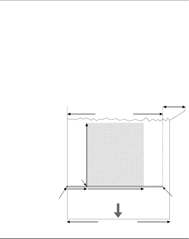
By setting up the X-start, the Width and the Length, you will create
a “print window” inside which the printing can be performed.
Any object or fi eld protruding outside the print window in any
direction will cause an error condition (Error 1003 “Field out
of label”).
Setup Parameters, cont'd.
Media, cont'd.
PAPER FEED
DIRECTION
Dot #0
Dot-line
on printhead
X-start Width (1–832)
Origin
Length
Dot #831
10.3 mm (0.41")
PRINT
WINDOW
PRINT
WINDOW
max. 104.0 mm (4.095")
25 – 114.3 mm (1 – 4.5")

Intermec EasyCoder F4 – Installation & Operation Ed. 248
Chapter 6 Setting Up the Printer
Media Type
The Media Type setup controls how the LSS and the paper feed
work. There are fi ve different media types:
• Label (w gaps) is used for adhesive labels mounted on
backing paper.
• Ticket (w mark) is used for labels, tickets, or strip provided with
black marks at the back of the paper web.
• Ticket (w gaps) is used for tickets and tags with detection slits.
• Fix length strip means that the length of the print window
decides the length of strip to be fed out.
• Var length strip adds 115 dots of paper feed after the last
printable dot (may even be a blank space character or a “white
dot” in an image or character cell) to allow the strip to be
properly torn off.
It is important to select the type, so the printer can indicate possible
paper errors. Two different error conditions may occur:
• Error 1005 “Out of paper” indicates that the last ordered copy
could not be printed because of an empty paper stock.
• Error 1031 “Next label not found” indicates that the last ordered
label or ticket was successfully printed, but no more labels/tickets
can be printed because of an empty paper stock.
Paper Type
The Paper Type setup controls the heat emitted from the printhead
to the transfer ribbon or direct thermal paper in order to produce
the dots that make up the printout image. Two parameters must
be set:
• Label Constant (range 50 – 115)
• Label Factor (range 10 – 50)
See the list on next page for recommended settings for various types
of standard Intermec direct thermal media.
Setup Parameters, cont'd.
Media, cont'd.
Intermec EasyCoder F4 – Installation & Operation Ed. 2 49
Chapter 6 Setting Up the Printer
Setup Parameters, cont'd.
Media, cont'd.
Recommended Settings
Intermec recommends the paper type and print speed settings listed
below to produce the highest possible print quality under normal
conditions and to ensure maximum lifetime of the printhead. Use
the EasySet bar code wand for easy media setup. Label materials
are available from Intermec either in standardized types and sizes,
or in special materials and sizes on request.
When adjusting the image darkness for individual requirements or
new label materials, proceed as follows:
Keep the Label Factor at the recommended value for the type
of direct thermal paper. Then decrease or increase the Label
Constant for lighter or darker images respectively, depending on the
requirements of the images or of the new label material.
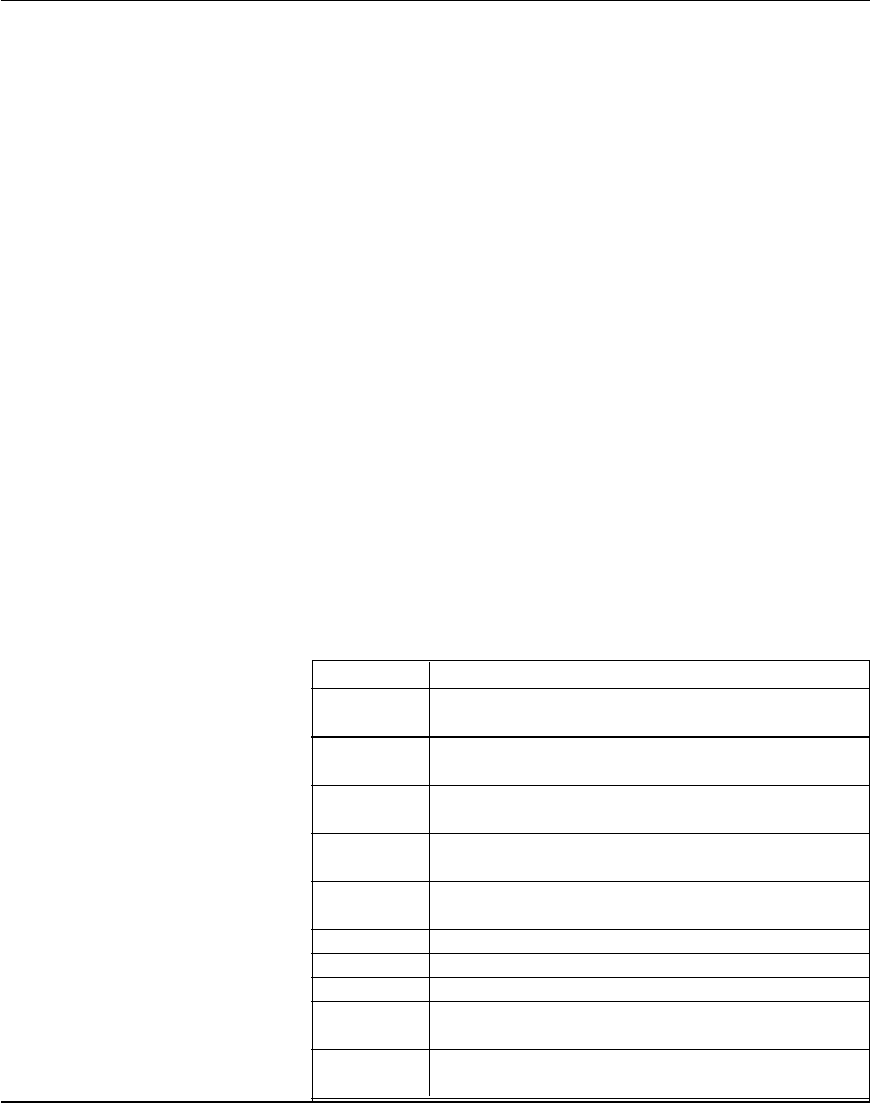
General Paper Type Settings Guide
Sensitivity1 Label Constant Label Factor Max. Speed3
Low 100 – 115 40 100
Standard 86 – 99 40 125
High 70 – 85 40 175
Ultra high 50 – 69 40 200
Direct Thermal Papers (Europe)
DT Type/ Paper Label Label Max Rec. Print Speed (mm/sec)3
Speed Designation Constant Factor Picket Fence Bar Code Ladder Bar Code
Top Coated/ Top Board2 100 40 100 100
Standard Premium 95 40 125 125
Non Top Coated/ Economy 85 40 125 125
Standard Eco Board2 80 40 175 175
Top Coated/High Premium High Speed 85 40 175 175
Direct Thermal Papers (North America)
DT Type/ Paper Label Label Max Rec. Print Speed (mm/sec)3
Speed Designation Constant Factor Picket Fence Bar Code Ladder Bar Code
Top Coated/ Duratherm II Tag2 112 40 100 100
Standard Duratherm II 95 40 100 100
Top Coated/ Duratherm Ltg 92 40 175 175
High Duratherm IR 82 40 150 150
1/. Please note that preprint and varnish decrease the sensitivity of the direct thermal paper.
2/. May require increased printhead pressure (see chapter 12 “Adjustments; Printhead Pressure”).
3/. Exceeding the recommended print speed may, even in case of plain text printing, cause premature wear-out of the
printhead

Intermec EasyCoder F4 – Installation & Operation Ed. 250
Chapter 6 Setting Up the Printer
Setup Parameters, cont'd.
Contrast
The contrast setup is used to make minor adjustments of the blackness
in the printout, e.g. to adapt the printer to variations in quality
between different batches of the same paper quality. 11 options are
displayed in an endless loop from -10% to +10%. Default value is
0%. The contrast is reset to default (±0) whenever a new paper type
is specifi ed, regardless which method has been used.
Testfeed
The sensitivity of the label stop sensor (LSS) may need to be
adjusted, e.g. when switching from one type of media to another.
This is especially the case when using self-adhesive labels fi tted on
a semi-transparent backing paper (liner). Adjusting the LSS entails
feeding out a number of blank copies until the fi rmware has decided
the proper setting for the LSS. At the same time, the front edges
of the labels, tickets etc. are detected so the paper feed control can
position the paper according to the Feedadjust setup (same as the
Intermec Fingerprint statement TESTFEED). The comparator and
amplifi er values of the LSS are displayed (read-only).
Head Resistance
The printhead resistance is measured automatically at startup and
displayed (read-only).
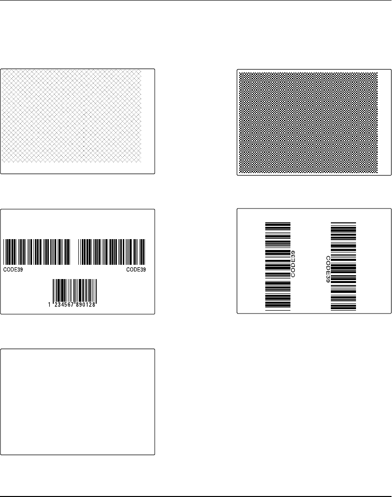
Testprint
Test label #1 – 4 are intended for checking the printout quality
and facilitate adjustment of the printhead pressure (see chapter
13“Adjustments”). Test label #5 lists the printer's current setup
(extra labels may be printed if the printer is fitted an optional
interface board). Test label #6 is only printed in connection with
the optional EasyLAN 100i interface board. The test labels #1 –
5 are illustrated on next page. If the printer refuses to print a test
label, press the <F3> key to fi nd out what is wrong, e.g. printhead
lifted or out-of paper.
Print Defi nes
• Head Resistance
• Testprint
• Print Speed
• LTS (optional)
Media, cont'd.
Intermec EasyCoder F4 – Installation & Operation Ed. 2 51
Chapter 6 Setting Up the Printer
Setup Parameters, cont'd.
Print Defi nes, cont'd.
Test Label #1 Test Label #2
Test Label #3 Test Label #4
Test Label #5
681 ohms/8 dots
UART1 9600-8-N-1
RTS/CTS DISABLE
ENQ/ACK DISABLE
XON/XOFF
DATA TO HOST DISABLE
DATA FROM HOST DISABLE
NEW LINE CR/LF
REC BUF 300
TRANS BUF 300
PRINT CONFIG
STARTADJ 0
STOPADJ 0
XSTART 24
WIDTH 808
LENGTH 1800
MEDIA TYPE LABEL (w GAPS)
PAPER TYPE DIRECT THERMAL
LABEL CONSTANT 85
LABEL FACTOR 40
CONTRAST +0%
TESTFEED 12 3
HEAD RESIST 681
PRINT SPEED 100
Odometer [km] 0
Model F4
Hardware version 3.0
Ram 4096 ( k)
Flash 0+2048 +1016 (k)
External 0 (k)
c: 1819504 bytes free
FIRMWARE
Fingerprint 7.31
MCS1147 xx-xx-00 xx:xx:xx m3k
slav0782 27-MAY-97 17:09:25 [0]
No keyboard slave [1]

Intermec EasyCoder F4 – Installation & Operation Ed. 252
Chapter 6 Setting Up the Printer
Print Speed
The print speed is variable between 100 and 200 mm/sec. Generally,
the lower the speed, the better the printout quality. This is especially
the case when printing bar codes with the bars running across
the paper web (“ladder style”), when printing on demanding face
materials, and when printing at low ambient temperatures. Refer to
the tables under “Media” earlier in this chapter for maximum print
speed values. The default setting is 100 mm/sec.
LTS (Label-Taken Sensor)
The sensitivity of the LTS may need to be adjusted according to
ambient light conditions and refl ective characteristics of the back side
of the paper. The LTS setup options are only displayed if an optional
label-taken sensor is installed in the printer.
• LTS Adjust:
Press <Enter>. A label is feed out. Remove the label and press
<Enter> again. A menu shows the sensitivity automatically
selected by the fi rmware and the range, in which the LTS
will work. Press <Enter> again and you will proceed to the
LTS Test menu.
• LTS Test:
Press <Enter>. A label is fed out. Remove the label and a new label
should be fed out automatically. Repeat until you are sure the LTS
works properly. Then press <Enter> to stop and exit.
• LTS Value:
Press <Enter>. You can enter a new value in the range indicated
in the LTS Adjust menu (see above). Min/max values are
in the range 0–10.
If an optional EasyLAN 100i interface board is fi tted, a number of
additional setup menus will be displayed. These menus are used
for setting up the IP address, the netmask, and the default router
for the EasyLAN 100i board, as described in separate manuals
delivered with the board.
Print Defi nes, cont'd.
Setup Parameters, cont'd.
Network
• IP Selection
• IP Address
• Netmask
• Default router

Intermec EasyCoder F4 – Installation & Operation Ed. 2 53
Chapter 7
The method of entering the Setup Mode depends on whether the
printer is fi tted with some kind of startup fi le, a subject that was more
thoroughly discussed in the chapter 4 “Starting Up” earlier in this
manual, to which the alphabetic references below refer.
A. EasyCoder F4 with Intermec Shell
• Turn on the power.
• When the display shows the message “Enter=Shell; x sec.”,
press <Enter>.
• Press the < Setup> key (this facility can be used anywhere
within Intermec Shell).
• Set up the printer as described in this chapter.
• Return to Intermec Shell by pressing the <Setup> key.
B. EasyCoder F4 with a custom-made application program
• Normally, there will be no need to enter the Setup Mode
for custom-made application programs. Necessary provisions
for changing the setup, manually or automatically, should be
provided by the program.
Entering
Setup Mode
at Installation
Setup Mode
Intermec EasyCoder F4 – Installation & Operation Ed. 254
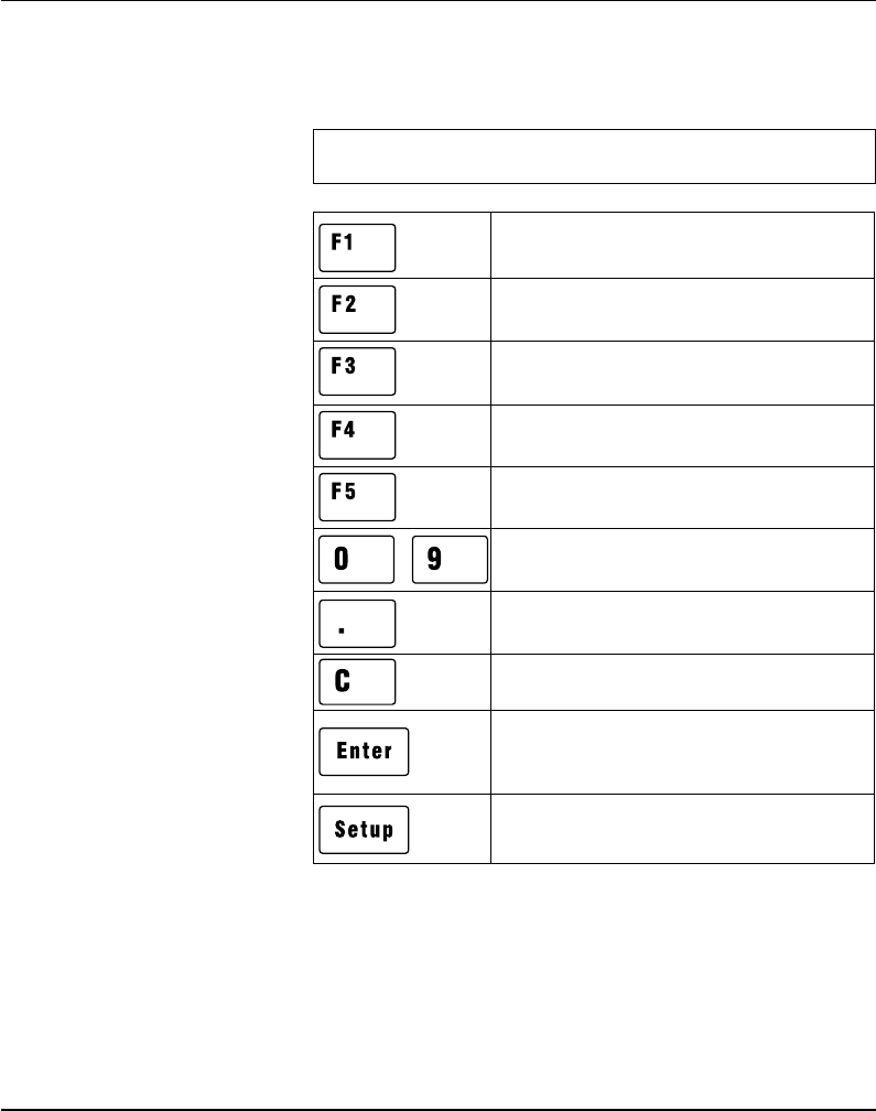
Chapter 7 Setup Mode
1/. “Left”, “right”, “up”, and “down” refer to the diagrams on
the following pages.
Move up one level or scroll back in a stack
of options1.
Move one menu to the right on the same
level1.
Move one menu to the left on the same
level1.
Specify negative values (leading position)
Enter numeric values.
Exit the Setup Mode.
(Can be used anywhere in the Setup Mode.)
Clear erroneously entered values.
Acknowledge and move to next menu.
Perform testfeeds in the Testfeed menu.
Print test labels in the Test Label menu.
Move down one level or scroll forward in a
stack of options1.
Display error message at test labels printing
failure.
-
Navigating in
Setup Mode
While going through the setup procedure, you are guided by texts in
the printer's display. You can step between setup menus, acknowledge
displayed values, select or type new values etc. by means of some of
the keys on the printer's keyboard.
Note!
An external keyboard cannot be used inside the Setup Mode.
Intermec EasyCoder F4 – Installation & Operation Ed. 2 55
Chapter 7 Setup Mode
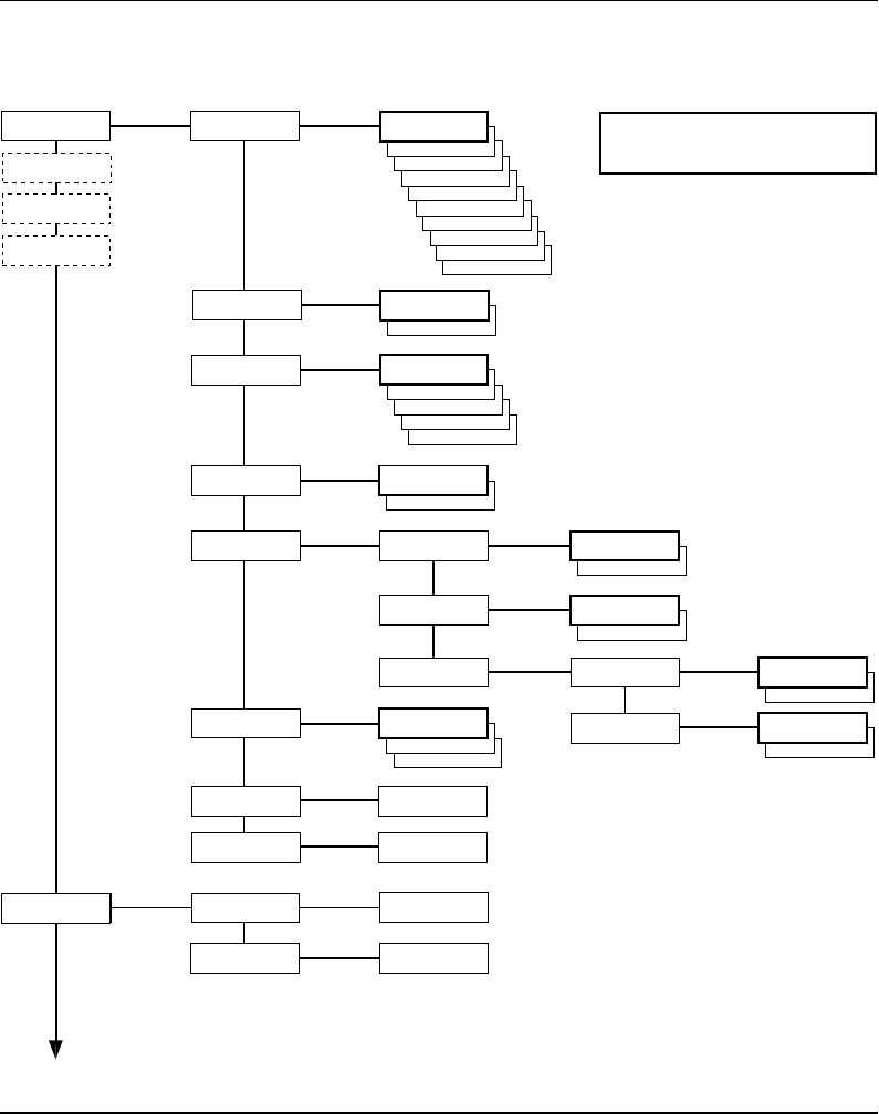
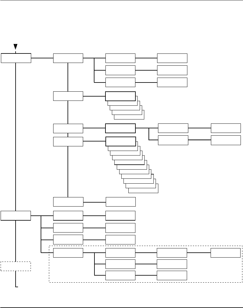
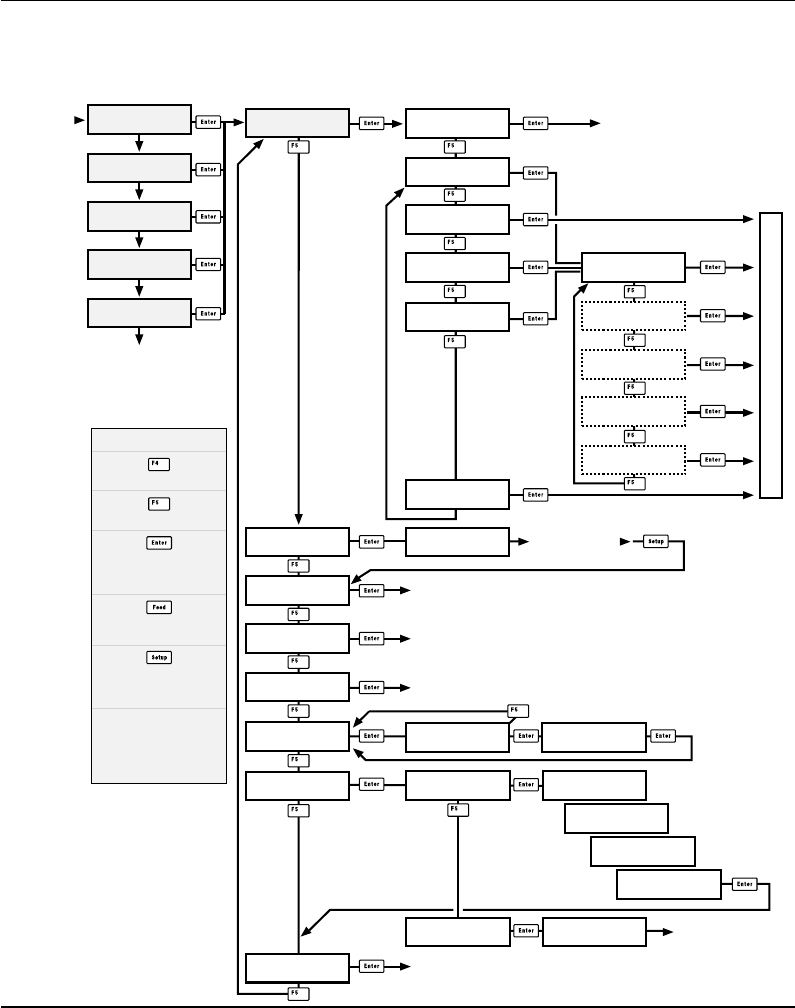
Setup Mode Overview, Part 1
(Intermec Fingerprint 7.31)
4800
2400
SETUP:
SER-COM,UART2
SETUP:
SER-COM,UART1
1200
600
300
115200
57600
38400
19200
SER-COM,UART1:
BAUDRATE
BAUDRATE:
9600
SPACE
MARK
ODD
EVEN
SER-COM,UART1:
PARITY
PARITY:
NONE
7
SER-COM,UART1:
CHAR LENGTH
CHAR LENGTH:
8
2
SER-COM,UART1:
STOP BITS
STOPBITS:
1
SER-COM,UART1:
FLOWCONTROL
FLOWCONTROL:
RTS/CTS
ENABLE
RTS/CTS:
DISABLE
FLOWCONTROL:
ENQ/ACK
ENABLE
ENQ/ACK:
DISABLE
FLOWCONTROL:
XON/XOFF
XON/XOFF:
DATA TO HOST
ENABLE
DATA TO HOST:
DISABLE
XON/XOFF:
DATA FROM HOST
ENABLE
DATA FROM HOST:
DISABLE
CR
LF
SER-COM,UART1:
NEW LINE
NEW LINE:
CR/LF
SER-COM,UART1:
REC BUF
REC BUF:
[300]:
SER-COM,UART1:
TRANS BUF
TRANS BUF:
[300]:
DETECTION:
FEEDADJ
SETUP:
FEEDADJ
FEEDADJ:
STOPADJ
STOPADJ:
[0]:
STARTADJ:
[0]:
Continued on next page!
LEGEND:
Boxes with thick lines indicate default setup
Boxes with dotted lines indicate menus related to
optional interface boards.
FEEDADJ:
STARTADJ
See Overview Part 3
See Overview Part 4
See Overview Part 5
SETUP:
SER-COM,UART3
SETUP:
NET-COM,NET1
Intermec EasyCoder F4 – Installation & Operation Ed. 256
Chapter 7 Setup Mode
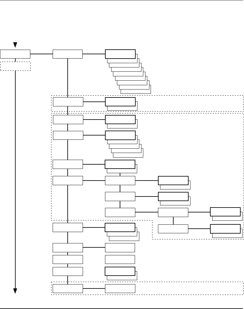
Setup Mode Overview, Part 2
(Intermec Fingerprint 7.31)
VAR LENGTH STRIP
FIX LENGTH STRIP
TICKET (w GAPS)
TICKET (w MARK)
MEDIA:
MEDIA SIZE
MEDIA:
CONTRAST
SETUP:
MEDIA
Use <F5> to select type of test label.
Press <Enter> to print it.
If no label is printed, press <F3> for error message.
• Press Setup key to exit the Setup Mode.
MEDIA SIZE:
XSTART
MEDIA SIZE:
WIDTH
MEDIA SIZE:
LENGTH
XSTART:
[24]:
WIDTH:
[832]:
LENGTH:
[1200]:
MEDIA:
MEDIA TYPE
MEDIA TYPE:
LABEL (w GAPS)
-2%
-4%
-6%
-8%
-10%
MEDIA TYPE:
+10%
+8%
+6%
+4%
+2%
CONTRAST:
+0%
PRINT DEFS:
HEAD RESIST
SETUP:
PRINT DEFS
SETUP:
NETWORK
HEAD RESIST:
[nnn]:
PRINT DEFS:
TESTPRINT
<ENTER> = PRINT:
<F5> = NEXT #1
Read-only value.
Printhead resistance is
automatically set at startup.
The LTS setup menus are
only displayed if an optional
LTS (Label-Taken Sensor)
is installed in the printer.
Continued from previous page!
PRINT SPEED:
[100]:
PRINT DEFS:
PRINT SPEED
LTS:
LTS ADJUST
PRINT DEFS:
LTS
LTS:
LTS TEST
LTS:
LTS VALUE
REMOVE LABEL AND
PRESS ENTER
SENSITIVITY 10
OUT OF 9–10
REMOVE LABEL
ENTER TO STOP
LTS VALUE:
[10]:
MEDIA:
PAPER TYPE
PAPER TYPE:
DIRECT THERMAL
MEDIA:
TESTFEED
TESTFEED:
[14 1]
• Press Enter key to perform a Testfeed.
• Comparator and amplifier values are read-only.
DIRECT THERMAL:
LABEL CONSTANT
DIRECT THERMAL:
LABEL FACTOR
LABEL CONSTANT:
[85]:
LABEL FACTOR:
[40]:
See Overview Part 5
Intermec EasyCoder F4 – Installation & Operation Ed. 2 57
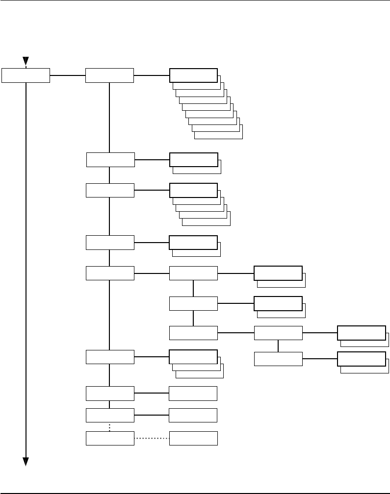
Chapter 7 Setup Mode
Setup Mode Overview, Part 3
(Intermec Fingerprint 7.31)
4800
SETUP:
SER-COM,UART2
2400
1200
600
300
57600
38400
19200
SER-COM,UART2:
BAUDRATE
BAUDRATE:
9600
SPACE
MARK
ODD
EVEN
SER-COM,UART2:
PARITY
PARITY:
NONE
7
SER-COM,UART2:
CHAR LENGTH
CHAR LENGTH:
8
2
SER-COM,UART2:
STOP BITS
STOPBITS:
1
SER-COM,UART2:
FLOWCONTROL
FLOWCONTROL:
RTS/CTS
ENABLE
RTS/CTS:
DISABLE
FLOWCONTROL:
ENQ/ACK
ENABLE
ENQ/ACK:
DISABLE
FLOWCONTROL:
XON/XOFF
XON/XOFF:
DATA TO HOST ENABLE
DATA TO HOST:
DISABLE
XON/XOFF:
DATA FROM HOST
ENABLE
DATA FROM HOST:
DISABLE
CR
LF
SER-COM,UART2:
NEW LINE
NEW LINE:
CR/LF
SER-COM,UART2:
REC BUF
REC BUF:
[300]:
SER-COM,UART2:
TRANS BUF
TRANS BUF:
[300]:
If an optional Double Serial or Industrial Interface Board is fitted, additional menus will be displayed
(in case of Double Serial Interface Board, also see Overview Part 4):
The selected type of hardware connection on "uart2:"
is displayed as one of the following alternatives (read-only):
• RS232
• 422 NON ISOLATED
• 422 ISOLATED
• RS485
These menus are only displayed if RS 485 is selected on "uart2:"
Enter printer's protocol address (0–31).
RTS/CTS flowcontrol cannot be
selected for the following types of
hardware connection on "uart2:":
• 422 NON ISOLATED
• 422 ISOLATED
SER-COM,UART2:
CONNECTED HW
SER-COM,UART2:
PROTOCOL ADDR.
PROTOCOL ADDR.
[1]:
SETUP:
SER-COM,UART3
These menus are not displayed if RS 485 is selected on "uart2:"
ENABLE
SER-COM,UART2:
PROT ADDR
PROT ADDR:
DISABLE
These menus are only displayed if RS 485 is selected on "uart2:"
INTELLITAG
R
CONECTED HW:
RS232
Intermec EasyCoder F4 – Installation & Operation Ed. 258
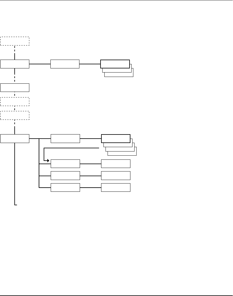
Chapter 7 Setup Mode
Setup Mode Overview, Part 4
(Intermec Fingerprint 7.31)
4800
SETUP:
SER-COM,UART3
2400
1200
600
300
57600
38400
19200
SER-COM,UART3:
BAUDRATE
BAUDRATE:
9600
SPACE
MARK
ODD
EVEN
SER-COM,UART3:
PARITY
PARITY:
NONE
7
SER-COM,UART3:
CHAR LENGTH
CHAR LENGTH:
8
2
SER-COM,UART3:
STOP BITS
STOPBITS:
1
SER-COM,UART3:
FLOWCONTROL
FLOWCONTROL:
RTS/CTS
ENABLE
RTS/CTS:
DISABLE
FLOWCONTROL:
ENQ/ACK
ENABLE
ENQ/ACK:
DISABLE
FLOWCONTROL:
XON/XOFF
XON/XOFF:
DATA TO HOST
ENABLE
DATA TO HOST:
DISABLE
XON/XOFF:
DATA FROM HOST
ENABLE
DATA FROM HOST:
DISABLE
CR
LF
SER-COM,UART3:
NEW LINE
NEW LINE:
CR/LF
SER-COM,UART3:
REC BUF
REC BUF:
[300]:
SER-COM,UART3:
TRANS BUF
TRANS BUF:
[300]:
If an optional Double Serial Interface Board is fitted, additional menus will be displayed:
The selected type of hardware connection on "uart3:"
is displayed as one of the following alternatives (read-only):
• RS232
• 422 NON ISOLATED
• CURRENT LOOP
RTS/CTS flowcontrol cannot be
selected for the following types of
hardware connection on "uart3:":
• 422 NON ISOLATED
• 20 mA CURRENT LOOP
SER-COM,UART3:
CONNECTED HW
CONNECTED HW:
RS232
Intermec EasyCoder F4 – Installation & Operation Ed. 2 59
Chapter 7 Setup Mode
Setup Mode Overview, Part 5
(Intermec Fingerprint 7.31)
• Press Setup key to exit the Setup Mode.
SETUP:
NET-COM, NET1
SETUP:
PRINT DEFS
SETUP:
MEDIA
SETUP:
FEEDADJ
SETUP:
SER-COM, UART1
Standard Setup Mode
See Overview Part 1
Standard Setup Mode
See Overview Part 1
Standard Setup Mode
See Overview Part 2
Standard Setup Mode
See Overview Part 2
Use keys . and 0–9 to enter netmask.
Use C-key to erase.
Use keys . and 0–9 to enter netmask.
Use C-key to erase.
NETWORK:
IP SELECTION
SETUP:
NETWORK
NETWORK:
IP ADDRESS
IP ADDRESS:
10.1.12.79
NETMASK:
255.255.0.0
NETWORK:
NETMASK
Use keys . and 0–9 to enter router.
Use C-key to erase.
NETWORK:
DEFAULT ROUTER
DEFAULT ROUTER:
10.1.12.1
RARP
BOOTP
DHCP
IP SELECTION:
MANUAL
CR
LF
NET-COM,NET1:
NEW LINE
NEW LINE:
CR/LF
If an optional an EasyLAN 100i interface board is fitted, additional menus will be displayed.

Intermec EasyCoder F4 – Installation & Operation Ed. 260
Chapter 8
Intermec Shell is a so called startup program (also called “autoexec-
fi le”), i.e. a program that automatically starts running when the
printer is turned on. Intermec Shell helps the operator to choose
between a number of standard or custom-made application programs
and to start certain useful facilities, as listed below.
Application Programs
• Intermec LabelShop (WYSIWYG label design program)
• Intermec Windows Driver (for printing Windows programs)
• Intermec Fingerprint (for creating your own programs)
• Intermec Direct Protocol (easy-to-use slave protocol)
• LINE_AXP.PRG (line analyzer program)
• Other application programs in the printer's memory1
Other Facilities
• Setup Mode (manual setup from printer's keyboard)
• Print Setup (printing setup on label)
• Testfeed (formfeeds + auto-adjust of the LSS)
• Test Label (printing of test labels)
• Default setup (resetting all setup parameters to default)
• Update PC-card (downloading data from a computer
to a PC-card inserted in the printer, or
upgrading the printer's fi rmware from
a PC-card)
• Reboot (restarting the printer)
Intermec Shell is factory-installed in the printer's permanent
memory (device "rom:"). This implies that if you insert a memory
card with another startup fi le before you turn on the printer, or
if there is a startup fi le stored in the printer's permanent memory
(device "c:"), this startup fi le will be used instead of Intermec
Shell (see chapter 4;“Startup Files”).
Intermec Shell Startup Program
Introduction
1/. A prerequisite is that the program is
provided with the extension “.PRG”.
However, some original Intermec utility
programs are excluded:
ERRHAND.PRG
FILELIST.PRG
LBLSHTXT.PRG
MKAUTO.PRG
LSS-SENSOR.PRG
SHELLXP.PRG
WINXP.PRG
Intermec EasyCoder F4 – Installation & Operation Ed. 2 61
Chapter 8 Intermec Shell Startup Program
A few seconds after you have turned on the power to the printer and
the initialization is completed, the countdown menu of the Intermec
Shell program will be displayed:
ENTER=SHELL
5 sec. v.4.4
Now you have 5 seconds to enter Intermec Shell by pressing the
<Enter> key.
Provided you have a working two-way communication with a
terminal program in a host computer, you may – as an alternative
– enter the Terminal Setup by transmitting “TTT” or “ttt” to the
printer. The Terminal Setup is described later in this chapter.
The lower line keeps you informed on how much time you have
left. Should the time run out before you have taken any action to
enter Intermec Shell, the last selected application in Intermec Shell
will be opened. This implies that if you use the same application
all the time, you will only need to turn on the power, once the
application has been selected.
If no other application has been selected yet, the default choice will
be displayed when the countdown is completed, e.g.:
FINGERPRINT
7.31
This message means that you have entered the immediate mode
of Intermec Fingerprint with "uart1:" (the standard RS 232C port)
selected as std I/O channel (see Intermec Fingerprint manuals).
If you want to enter another application, just restart the printer and
enter Intermec Shell before the countdown is completed.
If you enter the Intermec Shell from the countdown menus, the
Select Application menu will be displayed:
SHELL
SEL. APPLICATION
In this menu, you can choose between three options:
• Go to a stack of menus, where you can select an application
program, by pressing <Enter>.
• Go to the Facilities part of Intermec Shell by pressing <F5>.
• Start the Terminal Setup program by transmitting “TTT” or “ttt”
from the host.
Starting Up with
Intermec Shell

Intermec EasyCoder F4 – Installation & Operation Ed. 262
Chapter 8 Intermec Shell Startup Program
In Intermec Shell, the options are presented in stacks of menus,
organized as infi nite loops, where you can select the desired option,
as illustrated by the diagram below.
Select Application
The Select application option allows you to enter a stack of menus
showing the various application programs in the printer's memory.
• Current appl. starts the last selected application (by default
Intermec Fingerprint with "uart1:" selected as std I/O channel).
• Intermec LabelShop sets up the printer1 for the various
Intermec LabelShop label design programs for Microsoft
Windows. This option requires that you also select a std IN/OUT
channel, i.e. the channel you want to use for communication
between the printer and the computer. Refer to the Intermec
LabelShop manuals.
• Intermec Windows Driver selects the "centronics:" parallel
interface as standard IN channel and sets up the printer for
the various Intermec Windows Drivers, which you can use
on a personal computer to produce printouts from almost
any program run under Microsoft Windows. The Windows
Driver requires an optional Centronics interface board to be
fi tted in the printer.
• Intermec Fingerprint is used to create, modify or run programs
written in the Intermec Fingerprint programming language. This
option requires that you also select a standard IN/OUT channel,
i.e. the channel you want to use for communication between
the printer and the computer (normally "uart1:"). Refer to the
Intermec Fingerprint manuals.
• Intermec Direct Protocol is an easy-to-use printer protocol for
down-loading label layouts and variable input data to a printer
from a host computer. This option requires that you also select
a standard IN/OUT channel, i.e. the serial channel you want
to use for communication between the printer and the host.
Normally, select "uart1:". Refer to the Intermec Direct Protocol
Programmer's Guide.
• LINE-ALY.PRG (Line Analyzer) is a Fingerprint program that
captures characters received by the printer on a communication
channel and prints them on labels as described later in this
chapter.
• Other Application Programs
If the printer contains any other application programs – standard or
custom-made – these will presented as additional options.
Starting Up with
Intermec Shell,
cont'd.
1/. When the Intermec Labelshop
application is started, the printer's
communication setup is changed to
the following values:
Baudrate: 57600
Char. Length: 8
Parity: None
Stopbits: 1
RTS/CTS: Enable
ENQ/ACK: Disable
XON/XOFF to host: Disable
XON/XOFF from host: Disable
New Line: CR/LF
Receive buffer: 600
Transmit buffer: 600
If another application is selected
later, these setup parameters will
still be valid, unless the new
application includes instructions
to automatically change the setup.
The setup could also be changed
manually in the Setup Mode.

Intermec EasyCoder F4 – Installation & Operation Ed. 2 63
Chapter 8 Intermec Shell Startup Program
Select Other Facilities
As an alternative to selecting an application, you can step through a
number of other useful facilities:
• Setup allows you to enter the Setup Mode to set up the printer by
means of its built-in keyboard, see chapter 7 “Setup Mode”.
• Print Setup allows you to produce a printout of the printer's
current setup values (test label #5).
• Testfeed allows you to feed out a number of label, ticket, tag
or pieces of strip while the printer auto-adjusts its paper feed
and label stop sensor or black mark sensor. It is recommended
to perform a Testfeed operation each time you load a new roll
of labels (or similar).
• Test Label allows you to print a series of four test labels
(test labels #1 – #4) in order to test the printout quality and
printhead alignment. The labels are presented in an infi nite
loop, so you can print the series over and over again. Press
<Enter> for each new label.
• Default Setup allows you to reset all setup parameters to their
respective default values, as listed in chapter 6.
• Software Update is used for two purposes:
- Update PC-card allows the printer to be used as a Flash
PC-card programming device. By means of the Zmodem
commun-ication tool, fi les can be downloaded from a PC
to a Flash PC-card1 inserted in the memory card slot in
the printer's rear plate.
Warning! If the Flash PC-card contains an earlier fi rmware
version than the one in the printer, the printer's fi rmware will
be downgraded without warning.
- Update fi rmware is used to upgrade the printer's fi rmware from
a new fi rmware version stored as a fi le in a PC.
• Reboot has the same effect as turning off and on the power to
the printer. To exit Intermec Shell without having selected any
application program, use Reboot or restart the printer. Then wait
for the 5 seconds countdown without taking any action, and the
last selected application will be opened.
Starting Up with
Intermec Shell,
cont'd.
1/. Only Flash PC-cards approved
by Intermec can be used.
Intermec EasyCoder F4 – Installation & Operation Ed. 264
Chapter 8 Intermec Shell Startup Program
Intermec Shell 4.4 Diagram
SHELL
TEST LABEL
SHELL
TESTFEED
SHELL
DEFAULT SETUP
Performs a Testfeed, i.e. feeds out a number of blank copies
while autoadjusting the label stop sensor.
Prints test labels #1 – #4 in a loop.
Press Enter for each new label.
SHELL
REBOOT
Restarts the printer (same as power off/on)
Printer rebooted
automatically
STD I/O CHANNEL
UART1
STD I/O CHANNEL
UART2
STD I/O CHANNEL
UART3
SEL. APPLICATION
Fingerprint 7.31
SHELL
SETUP
See “Setup Mode”
Prints a list of current setup values (test label #5).
Note 1: Dotted options are only shown if
an appropriate optional interface pcb is fitted.
The Windows driver option requires an
optional Centronics interface pcb.
See note 1
See note 1
SHELL
PRINT SETUP
SEL. APPLICATION
WINDOWS DRIVER
ENTER=SHELL
5 sec. v.4.4
ENTER=SHELL
4 sec. v.4.4
ENTER=SHELL
3 sec. v.4.4
ENTER=SHELL
2 sec. v.4.4
ENTER=SHELL
1 sec. v.4.4
Last selected
application is started
Default:
Fingerprint 7.31
w. std I/O = "uart1:"
Last selected application is started
The selected application is started
POWER ON
Return to previous menu.
Proceed to next menu.
Accept displayed option
and proceed, or
execute displayed option.
Perform a Testfeed
anywhere in Intermec Shell.
Enter the Setup Mode
from anywhere
in Intermec Shell.
Legend:
SHELL
SEL. APPLICATION
SEL. APPLICATION
Direct Protocol
SEL.APPL rom:
LINE_AXP.PRG
SETUP:
SER-COM,UART1
SEL. APPLICATION
LABELSHOP
SEL. APPLICATION
CURRENT APPL.
Enter Terminal Setup
by transmitting T T T
or t t t to printer,
when menus marked with a
shade of grey are displayed!
ARE YOU SURE ?
Y=ENTER/ N=F5
DEFAULT SETUP
PERFORMED
SHELL
SOFTWARE UPDATE
UPDATE:
PC-CARD?
UPDATE:
FIRMWARE
PC-CARD ERASE
TRANSFER FILE
USING ZMODEM
PROGRAMMING
PC-CARD
PROGRAMMING
COMPLETED
TRANSFER FILE
USING ZMODEM
STD I/O CHANNEL
CENTRONICS
See note 1
STD I/O CHANNEL
net1:
See note 1

Intermec EasyCoder F4 – Installation & Operation Ed. 2 65
Chapter 8 Intermec Shell Startup Program
The Terminal Setup program in Intermec Shell allows the operator
to control the whole Intermec Shell program remotely from a host
computer or terminal and also to read or change the printer's setup.
Obvious prerequisites are that there must be a working two-way
(serial) communication between printer and host, and that the
host runs a suitable communication program (e.g. MS Windows
Terminal) that can transmit and receive data in ASCII format, i.e. as
printable characters. Set up the terminal as VT100.
Enter Terminal Setup by transmitting three upper- or lowercase T
characters (TTT or ttt) while the printer either shows the Intermec
Shell countdown menus or the Select Application menu.
If this does not work, the communication protocols of the printer and
the host probably do not match, or there is some other communication
error, e.g. a defect communication cable, wrong port selected
on the host, or cable connected to some other port than "uart1:"
on the printer1.
You can check and change the printer's setup in the Setup Mode,
which you can enter by pressing the <Setup> key on the printer's
built-in keyboard. Proceed as described in chapter 8 “Setup Mode”.
Among the facilities in Intermec Shell, you will also fi nd a number
of options that allow you to read or change the communication
setup of the printer:
• Setup
This is another way of entering the Setup Mode, where you
can browse through the setup parameters and make changes by
means of the printer's keyboard.
• Print Setup
Here you can print the current setup on one or more labels.
• Default Setup
This option allows you to reset the communication parameters
for all serial communication channels on the printer to default
values.
Change the communication setup of the printer according to the
host or vice versa.
Once printer and host has been set up with the same communication
parameters, go to the “Select Application” menu and use the triple
T (TTT or ttt) to start Terminal Setup.
Terminal Setup
Starting Terminal Setup
Solving Communication
Problems
1/. By default , "uart1:" is standard IN /OUT
channel and should be used for communi-
cation between printer and host, e.g. for
running Terminal Setup or for program-
ming. However, other ports could be
appointed standard IN and/or OUT chan-
nel by means of the Intermec Fingerprint
statement SETSTDIO. Refer to the Inter-
mec Fingerprint manuals for further
information.
Intermec EasyCoder F4 – Installation & Operation Ed. 266
Chapter 8 Intermec Shell Startup Program
The Terminal Setup program is self-instructing by means of prompts.
You can move around in Intermec Shell in the same manner as
when you control Intermec Shell manually by means of the printer's
display and keyboard.
The Setup part of Terminal Setup follows the same structure as
setup fi les, see later in this chapter. Comprehensive explanations of
the various setup parameters can be found in Chapter 7 “Setting
Up the Printer”.
When you transmit the triple T (TTT or ttt) to the printer, the
following message will appear on printer's display:
SETUP FROM
TERMINAL
On the screen of the host, another message will appear:
-----------------------------------------------
Welcome to SHELL v.4.4 in terminal mode
-----------------------------------------------
Answer Y <CR> for Yes, <CR> for No.
----------------
SHELL
SEL. APPLICATION
----------------
(Y / N / B):
From here on, you can move around in Intermec Shell according
to the diagram in the chapter “Using Intermec Shell” by answering
Y (=Yes), N (=No), or B (=Back) to the prompts that successively
appear on the screen.
Note that the program also accepts the corresponding lowercase
characters, i.e. y, n, and b.
Terminal Setup, cont'd.
Using Terminal Setup

Intermec EasyCoder F4 – Installation & Operation Ed. 2 67
Chapter 8 Intermec Shell Startup Program
This example shows how you for example can select the Intermec
Fingerprint application:
----------------
SHELL
SEL. APPLICATION
----------------
(Y / N / B):Y
----------------
SEL. APPLICATION
CURRENT APPL.
----------------
(Y / N / B):N
----------------
SEL. APPLICATION
LABELSHOP
----------------
(Y / N / B):N
----------------
SEL. APPLICATION
WINDOWS DRIVER
----------------
(Y / N / B):N
----------------
SEL. APPLICATION
Fingerprint 7.31
----------------
(Y / N / B):Y
----------------
STD I/O CHANNEL
UART1
----------------
(Y / N / B):Y
When you have answered the fi nal prompt, the printer will start
the selected application.
Terminal Setup, cont'd.
Selecting an Application
Intermec EasyCoder F4 – Installation & Operation Ed. 268
Chapter 8 Intermec Shell Startup Program
Terminal Setup, cont'd.
Changing the Setup
To set up the printer or use any other of the facilities, answer N
(=No) to the “Select Application” prompt. The following example
illustrates how to enter the Setup Mode:
----------------
SHELL
SEL. APPLICATION
----------------
(Y / N / B):N
----------------
SHELL
SETUP
----------------
(Y / N / B):Y
----------------
SETUP:
SER-COM,UART1
From here you can navigate through the Setup Mode by means of
keys on a VT100 terminal according to the same principles as when
using the printer's own keyboard (see overviews in chapter 7):
Key Action
u Move one menu to the left on the same level (same
as <F1>).
d Move one menu to the right on the same level (same
as <F2>).
e Display error message at test label printing failure
(same as <F3>).
b Move up one level or scroll back in a stack of menus
(same as <F4 >).
f Move down one level or scroll forward in a stack
of options (same as <F5>).
x Exit the setup (same as <Setup>).
0 – 9 Enter numeric values.
. Specify negative values (same as < . >).
Enter Acknowledge and move to next menu, perform
testfeeds, or print test labels (same as <Enter>).
Backspace Delete one character to the left of the cursor (same
as <C>).

Intermec EasyCoder F4 – Installation & Operation Ed. 2 69
Chapter 8 Intermec Shell Startup Program
To exit the Terminal Setup program, e.g. after having changed
the setup, you must select the Reboot option after having stepped
through all the facility options, as illustrated below:
----------------
SHELL
PRINT SETUP
----------------
(Y / N / B):N
----------------
SHELL
TESTFEED
----------------
(Y / N / B):N
----------------
SHELL
TEST LABEL
----------------
(Y / N / B):N
----------------
SHELL
DEFAULT SETUP
----------------
(Y / N / B):N
----------------
SHELL
SOFTWARE UPDATE
----------------
(Y / N / B):N
----------------
SHELL
REBOOT
----------------
(Y / N / B):Y
Terminal Setup, cont'd.
Exiting Terminal Setup
Intermec EasyCoder F4 – Installation & Operation Ed. 270
Chapter 8 Intermec Shell Startup Program
The Line Analyzer (LINE_AXP.PRG) is a program written in
the Intermec Fingerprint programming language and intended
to help solving possible communication problems. As the name
implies, the Line Analyzer captures all incoming characters on
a specified communication channel and prints them on one or
several labels.
Printable characters are printed in black-on-white, whereas control
characters and space characters (ASCII 00–32 dec) are printed in
white on a black background.
While the printer is receiving data, the “Ready” control lamp blinks.
There is a 0.5 sec timeout. If no more character has been received
after 0.5 seconds, the program considers the transmission terminated
and prints out a label.
As long as a continuous string of characters is being received,
the program wraps the lines until the label is full and then starts
to print another label. At the bottom of each label, the following
information is printed:
• Page number
• Number of characters printed on the label
• Total of characters received so far
The Line Analyzer is displayed as the option “LINE_ALY.PRG"
under the “SEL. APPLICATION” menu. After the Line Analyzer
has been selected and the printer has started up again, the printer
feeds out two labels and the following menu is displayed:
Line Analyzer
Sel.port(1-4) 1
Enter the desired communication port by means of the numeric
keys on the printer's keyboard:
1 = "uart1:"
2 = "uart2:"
3 = "uart3:"
4 = "centronics:"
5 = "net1:"
If the printer is not fi tted with the specifi ed port, an error message
appears in the display and you can select another port:
Line Analyzer
Error:56
Line Analyzer
Intermec EasyCoder F4 – Installation & Operation Ed. 2 71
Chapter 9
Options
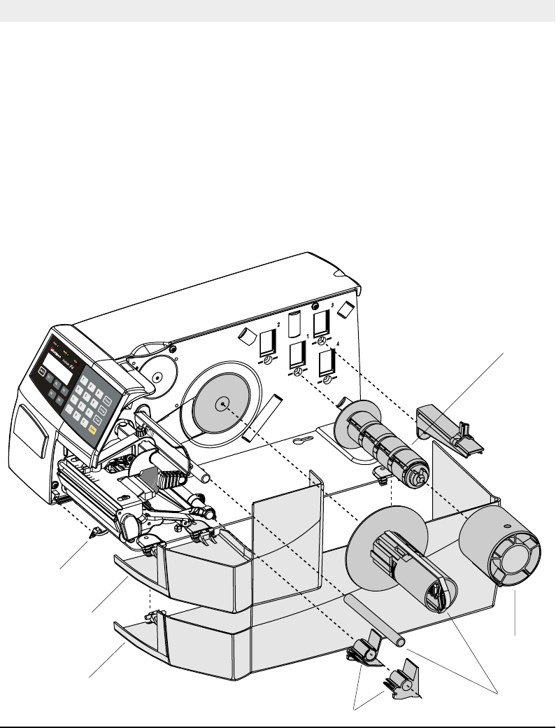
Introduction
The EasyCoder F4 is designed to provide a high degree of fl exibility
by means of a modular design. By adding a collection of optional
devices to the basic concept, the printer can be adapted for a variety
of applications. Most options can easily be installed by the operator
whereas some options should be installed by an authorized service
technician, or are only available as factory-installed options.
Below is a description of some of the many options available
for EasyCoder F4.
Rewinder &
Guide Shaft
3" Adapter
Quick-Load Guides
Label-Taken
Sensor
Short Side Door
1.5" Paper
Spool
Long Side Door

Intermec EasyCoder F4 – Installation & Operation Ed. 272
Chapter 9 Options
The EasyCoder F4 comes with either a short side door, that only
covers the print unit, or with a long side door, that encloses the entire
paper compartment. The long side door has a slot for external paper
supply. The long side door is generally illustrated throughout this
manual, but pictures of the short side door can be found at the start of
this chapter and in chapter 5 “Paper Load/Quick-Load”.
The rewind unit is an optional device for peel-off operation, i.e. the
labels are separated from a backing paper (liner) after printing and
the backing paper is wound up on an internal spool. The rewind kit
also includes a guide shaft.
Peel-off cannot be combined with quick-load guides, see below.
The rotating paper supply spool is designed to fi t paper roll cores with
an internal diameter of 38 – 40 mm (1.5"). The spool can be fi tted in
the same positions as the paper hanger (see chapter 3 “Installation”).
Being factory installed, the position of the paper supply spool is not
intended to be changed by the operator.
the combination of high print speed and the momentum of large
and heavy paper roll (may cause slacks and jerks in the paper web
that may impair the printout quality, especially when printing
ladder style bar codes (i.e. with bars running across the web).
Thus, in case of print speed exceeding 150 mm/sec. (6"/sec,) in
combination with a full width paper roll and a paper roll diameter
of 200 mm (8") or more, we do not recommend the use of a rotating
paper supply spool.
The 3 inch/76 mm adapter is used in connection with a rotating
paper supply spool and makes it possible to use paper rolls with 3
inch/76 mm inner diameter paper cores. The 3" adapter cannot be
used in connection with a paper hanger.
The adapter is pressed onto the paper supply spool and held in
place by a screw
Side Doors
Rewind Unit
3" Adapter
Paper Supply
Spool

Intermec EasyCoder F4 – Installation & Operation Ed. 2 73
Chapter 9 Options
For Quick-Load operation (see chapter 5 “Paper Load”), a set of
paper guides is fi tted at the rear of the print unit instead of the
standard guide ring. The outer guide is adjustable for different
paper widths. The quick-load guides are included as standard in
the delivery (either factory-fi tted or loose). They can easily be
fi tted by the operator:
1. Open the upper paper guide (see illustration in chapter 11
“Maintenance/Cleaning the Paper Guides”).
2. Pull out the standard guide ring from the shaft.
3. Fit the quick-load guides onto the shaft as illustrated on the
fi rst page of this chapter.
The Label-Taken Sensor (LTS) is a photoelectric sensor, which
enables the printer's fi rmware to detect if the latest printed label,
ticket, tag etc. has been removed before printing another copy.
The LTS can be enabled or disabled by means of the instructions
LTS& ON and LTS& OFF respectively in Intermec Fingerprint and
the Intermec Direct Protocol.
The EasySet bar code wand is primarily intended to facilitate setup
in regard of paper type, but can also be used to change all other
setup parameters. This is done by scanning a pre-printed CODE
128 bar code composed according to a special standard (FNC3 in
the bar code input data specifi es a setup parameter). The bar code
wand can also be used to read other CODE 128 bar codes as input
data to a Intermec Fingerprint program.
A selection of setup bar codes is provided in Appendix 4. For further
information on how to compose setup bar codes, see the Intermec
Fingerprint 7.xx Reference Manual.
The bar code wand is connected to the topmost connector on the
printer's rear plate, immediately to the right of the main switch.
The Real-Time Clock circuit (RTC) relieves the operator or the
overhead computer system from having to set the clock/calendar by
means of the Intermec Fingerprint instructions DATE$ and TIME$
after each power up. The RTC has its own battery backup with a
life of 10 years or more.
Real-Time Clock
EasySet Bar Code
Wand
Quick-Load
Guides
Label-Taken
Sensor

Intermec EasyCoder F4 – Installation & Operation Ed. 274
Chapter 9 Options
Interface Boards
A number of different interface boards are available for use with the
EasyCoder F4. The interface boards are either factory fi tted or can
easily be fi tted by an authorized service technician.
The EasyCoder F4 can accommodate one such interface board.
The interface boards for the EasyCoder F4 are presently:
• Parallel Interface Board (IEEE 1284)
• Double Serial Interface Board
• Industrial Interface Board
• EasyLAN 100i Interface Board (Ethernet)
Refer to Appendix 3 “Interfaces” for more information on interface
boards.
RFID Option
RFID (radio frequency identification) option modules are available
for use with the EasyCoder F4. The RFID option modules are
either factory fitted or fitted by an authorized service technician.
The EasyCoder F4 can accommodate only one option module. The
RFID option module occupies the same chassis slot as other inter-
face boards listed in Chapter 9, and cannot be used in conjunction
with, or in addition to, any of the optional interface boards listed.
Intermec EasyCoder F4 – Installation & Operation Ed. 2 75
Chapter 10
Troubleshooting
Symptom Possible Cause Remedy Refer to
Overall weak printout Wrong Paper Type setup Change setup Chapter 6
Low Contrast setup Change setup Chapter 6
Printhead pressure too low Adjust Chapter 12
Worn printhead Replace printhead Chapter 11
Wrong printhead voltage Replace CPU board ☎ Call Service
Printout weaker on one side Uneven printhead pressure Adjust arm alignment Chapter 13
Weak spots Foreign particles on paper Clean or replace Chapters 5
Poor paper quality Use Intermec paper Appendix 2
Worn printhead Replace printhead Chapter 11
Worn platen roller Check/replace ☎ Call Service
Overall dark printout Wrong Paper Type setup Change setup Chapter 6
Too high Contrast setup value Change setup Chapter 6
Printhead pressure too high Adjust Chapter 12
Wrong printhead voltage Replace CPU board ☎ Call Service
Excessive bleeding Wrong Paper Type setup Change setup Chapter 6
Contrast setup value too high Change setup Chapter 6
Printhead pressure too high Adjust Chapter 12
Faulty energy control Replace CPU board ☎ Call Service
Dark lines along paper web Foreign objects on printhead Clean printhead Chapter 11
White lines along paper web Printhead dirty Clean printhead Chapter 11
Missing dots on printhead Replace printhead Chapter 11
Large part of dot line missing Wrong X-start or Width setup Change setup Chapter 6
Failing printhead Replace printhead Chapter 11
Failing strobe signal Check CPU-board ☎ Call Service
Printout missing along inner edge Bad paper alignment Adjust Chapter 5
Small core and hanger in upper position Move hanger to lower pos. Chapter 3
X-start setup value too low Increase Chapter 6
Paper feed not working properly Changed media characteristics Perform a TESTFEED Chapter 5
Wrong start- and stop adjust values Check/change Chapter 6
Wrong Media Type setup Check/change Chapter 6
Wrong sensor position Check/change Chapter 12
Dirty or blocked sensors Clean paper guides Chapter 11
Faulty sensors Replace ☎ Call Service
Use this list to correct possible printout troubles or fl aws in printout
quality, and to decide when assistance from the Service dept. of the
nearest Intermec distributor is required. Note that most problems are
due to operating errors or normal wear of the printhead.
Intermec EasyCoder F4 – Installation & Operation Ed. 276
Chapter 11
Maintenance
Printhead
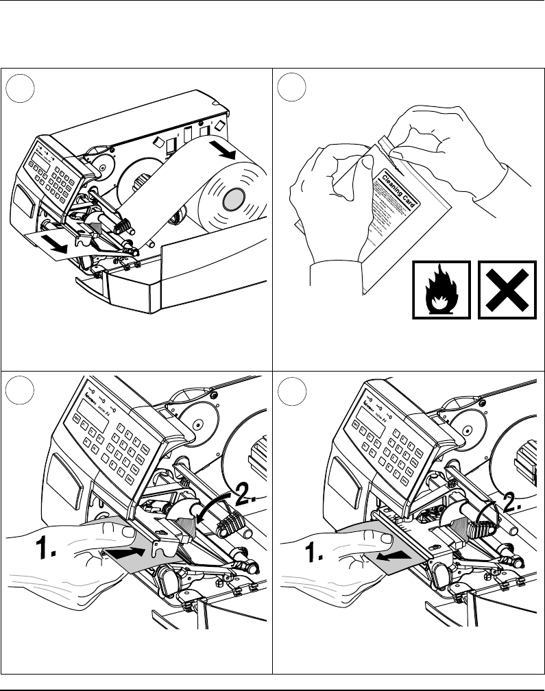
Cleaning
Cleaning of the printhead on a regular basis, preferably in connection
with each ribbon or paper load, is important for the life of the
printhead and for the printout quality. Below is a description of how
to clean the printhead by means of Cleaning Cards. If additional
cleaning is required, e.g. for removing adhesive residue from the
platen roller or tear-off edge, use a cotton swab moistened with
isopropyl alcohol.
Caution!
Isopropyl alcohol [(CH
3)2CHOH; CAS 67-63-0] is a highly
fl ammable, moderately toxic and mildly irritating substance.
Open the side door. Turn the printhead lift knob clockwise to lift
the printhead.
1 2
Intermec EasyCoder F4 – Installation & Operation Ed. 2 77
Chapter 11 Maintenance
Printhead Cleaning, cont'd.
Remove the paper, if any. Open the cleaning card envelope and pull out
the cleaning card. Read the warning text.
34
Pull out the cleaning card (1) and open the
printhead (2).
Insert most of the cleaning card under the
printhead (1). Close the printhead (2).
6
5