Transact Campus SE3100X006 Card Reader User Manual 1291 SE3RDR100 Install DRAFTf
Blackboard Inc. Card Reader 1291 SE3RDR100 Install DRAFTf
Contents
- 1. User Manual 1
- 2. User manual 2
User Manual 1


Contents
P
RINTED
N
OVEMBER
24, 2009
I
2
SE3-RDR100 I
NSTALLATION
G
UIDE
3 Install the SE3-RDR100
3 Surface Mount the SE3-RDR100
6 Single Gang Box Mount the SE3-RDR100
9 Remove the SE3-RDR100
10 Specifications

Figures
P
RINTED
N
OVEMBER
24, 2009
II
Figure 1-1 SE3-RDR100 Reader.................................................................................2
Figure 1-2 Mounting Drill Pattern.................................................................................3
Figure 1-3 Mounting Plate Installa
tion - Mullion
...........................................................4
Figure 1-4 Mounting Plate Installati
on - Surf
ace Mount...............................................5
Figure 1-5 Mullion Installation......................................................................................5
Figure 1-6 Single Gang Box Mount Assembly.............................................................6
Figure 1-7 Mounting Plate Installa
tion - Gang
Box Mount...........................................7
Figure 1-8 Single Gang Box Mount .............................................................................7
Figure 1-9 SE3-RDR100 Wiring ..................................................................................8
Figure 1-10 SE3-RDR100 Mounting Removal...............................................................9
S E 3 - R D R 1 0 0 I N S T A L L A T I O N GU I D E
DO C U M E N T 1 2 9 1 R E V 0 1
P
RINTED
N
OVEMBER
24, 2009
1-1
This device complies with Part 15 of the FCC Rules. Operation is subject to the following two conditions: (1) This device
may not cause harmful interference, and (2) this device must accept any interference received, including interference that
may cause undesired operation.
Part 15.21: Changes or modifications not expressly approved by the party responsible for complianc
rity
to operate the equipment.
NOTE:
T
he manufacturer is not responsible for any radio or TV inte
rference caused by unauthorized modi
fications to this equipment.
This equipment complies with the FCC radi
a
tion exposure limits set forth for an unc
ontrolled environment. End users must follow
the
specific operating instructions for satisf
ying RF exposure compliance. The antenna(s)
used for this transmitter must be install
ed to
provide a separation distance of at least 20
cm from all persons and must not be co-l
ocated or operating in conjunction with an
y other
antenna or transmitter.
Blackboard Inc. SE3-RDR100
Tested To Comply
With FCC Standards
FOR HOME OR OFFICE USE
This Class B digital apparatus complies with
Canadian ICES-003
Cet appareill numérique de la classes B est conform
à la norme NMB-003 du Canada
P
RINTED
N
OVEMBER
24, 2009
1-2
SE3-RDR100 INSTALLATION GUIDE
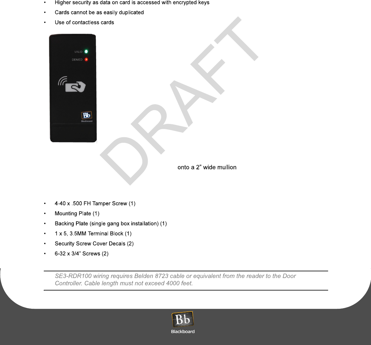
The Blackboard SE3-RDR100 is a Door Access Reader that supports contactless card technology.
Contactless Card Technology offers the
following advantages vs. magnetic stripe:
virtual
ly eliminates reader wear and
tear (card need not contact the reader)
Figure 1-1 SE3-RDR100 Reader
The SE3-RDR100 Card Reader may
be mounted
or a single gang box using the
included backing plate.
The following items are included with the SE3-RDR100:
S E 3 - R D R 1 0 0 I N S T A L L A T I O N GU I D E
DO C U M E N T 1 2 9 1 R E V 0 1
P
RINTED
N
OVEMBER
24, 2009
1-3
I
NSTALL
THE
SE3-RDR100
UL Considerations:
Attention to Installers: All fi
eld wiring/cabling conn
ections made to the Controller need
to use shielded cable with one of the shielded ends connected to earth ground.
Surface Mount the SE3-RDR100
(page
1-3)
Single Gang Box Mount the SE3-RDR100
(page
1-6)
The mounting plate is secured using #6 flat head
ha
rdware. Select hardware based on the mounting
material.
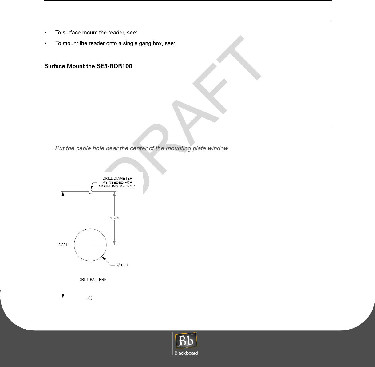
To surface mount the SE3-RDR100
1
Use the mounting plate as a template to mark mounting holes and a cable routing hole.
2
Drill the holes for the mounting hardware (#6 flathead screws) and the cable.
Figure 1-2 Mounting Drill Pattern
IN S T A L L T H E S E 3 - R D R 1 0 0
P
RINTED
N
OVEMBER
24, 2009
1-4
3
Secure the mounting plate with the chosen hardware.
Figure 1-3 Mounting Plate Installation - Mullion
4
Pull the cable through the hole, and then wire to the 5-pin terminal block.
SE3-RDR100 Wiring
5
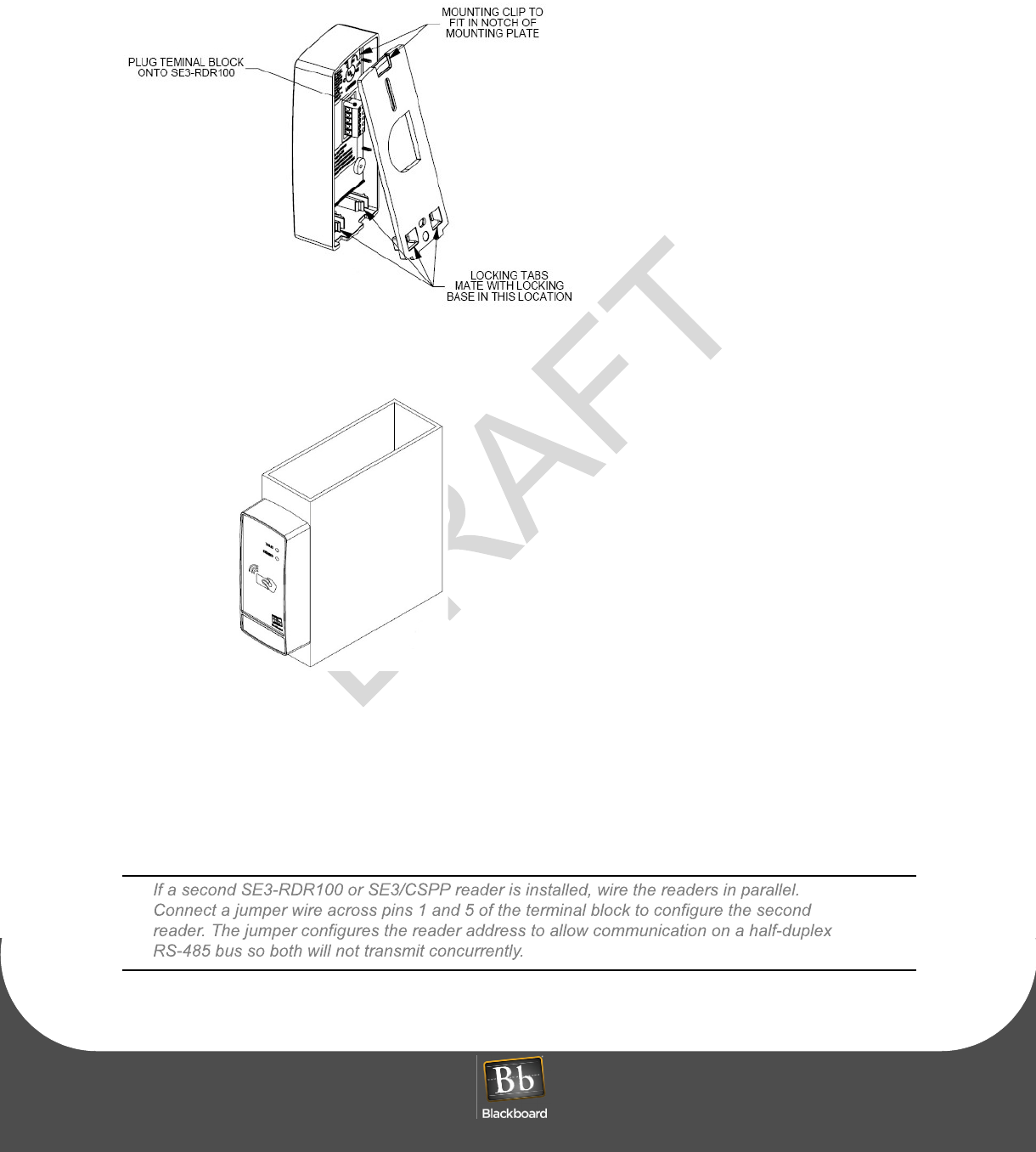
Plug the terminal block onto the SE3-RDR100.
6
Place SE3-RDR100 at an angle over the mounting plat
e, and then slide down to engage the clip onto
the mounting plate notch.
S E 3 - R D R 1 0 0 I N S T A L L A T I O N GU I D E
DO C U M E N T 1 2 9 1 R E V 0 1
P
RINTED
N
OVEMBER
24, 2009
1-5
Figure 1-4 Mounting Plate Installation - Surface Mount
7
Push
the bottom of the reader onto the mounti
ng plate to lock the unit to the plate.
Figure 1-5 Mullion Installation
8
Test the SE3-RDR100 for proper operation.
9
Optionally secure the reader to the mounting plate
using the security screw supplied in the hardware
kit.
10
Apply the Security Screw Cover Decal.
IN S T A L L T H E S E 3 - R D R 1 0 0
P
RINTED
N
OVEMBER
24, 2009
1-6
To mount the SE3-RDR100 on
to a single gang box
1
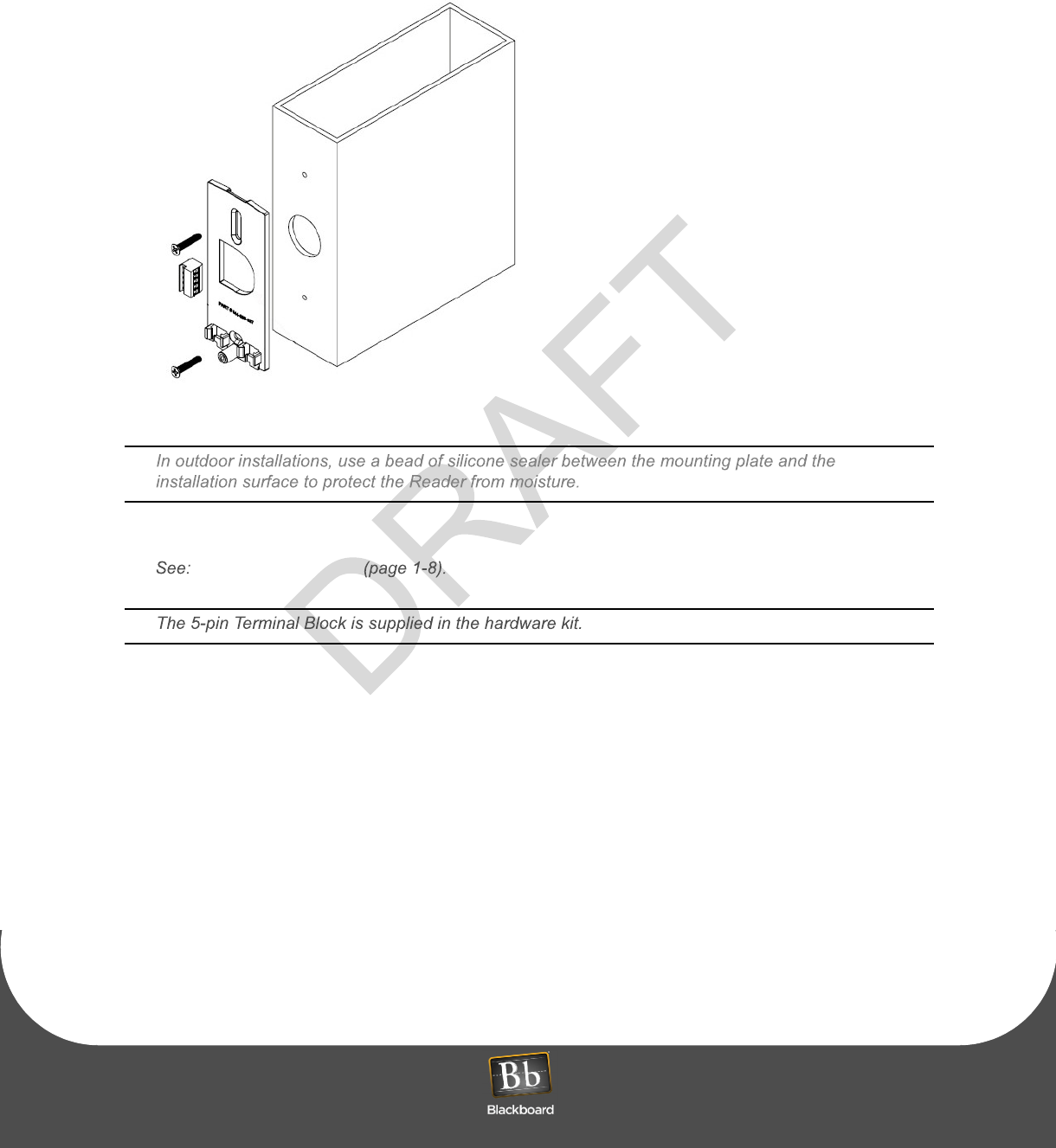
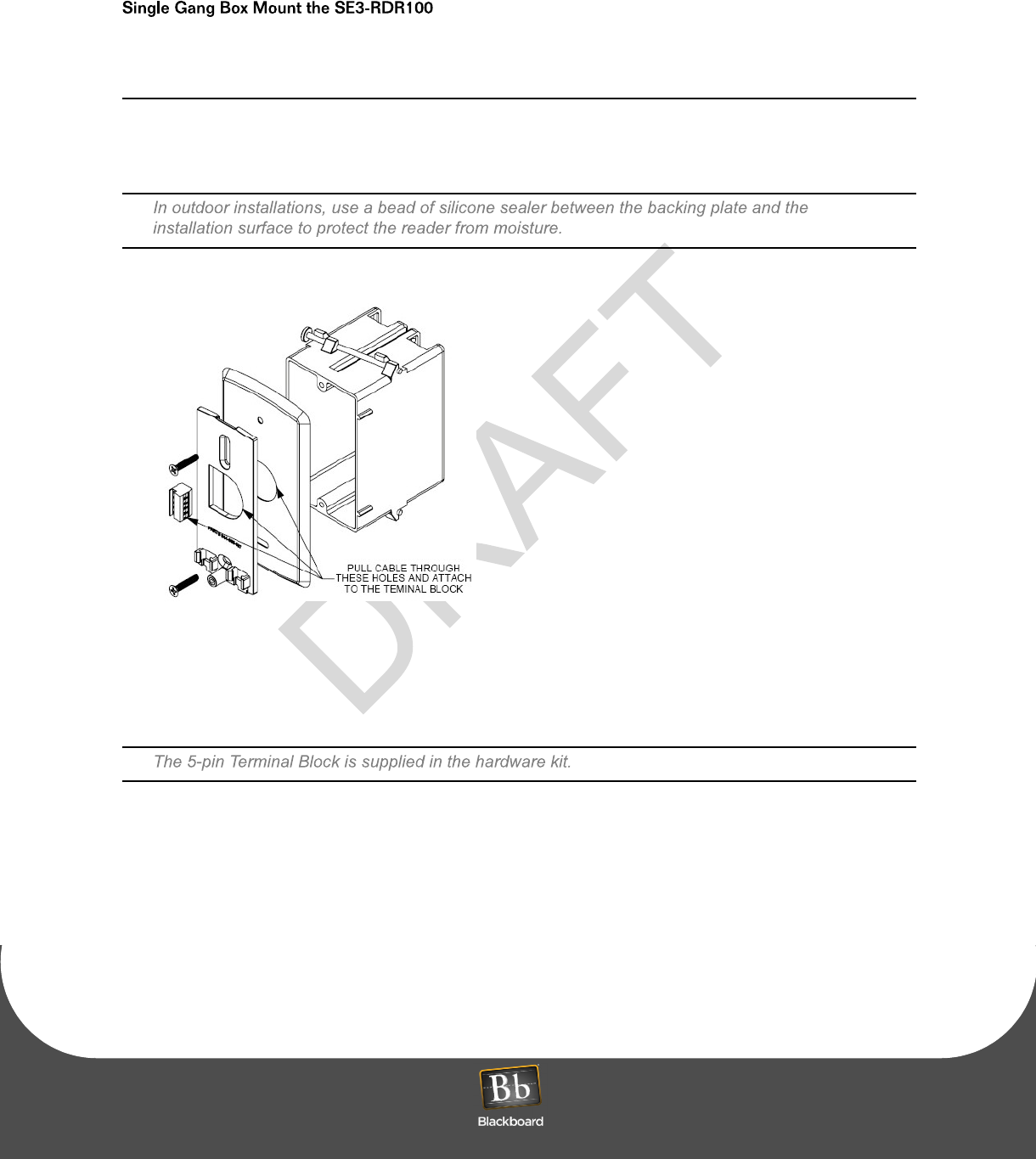
Secure the backing and mounting plates with the appropriate hardware to the single gang box.
Figure 1-6 Single Gang Box Mount Assembly
2
Pull cable through mounting plate, and then connect to 5-pin terminal block,
see:
SE3-RDR100 Wiring
(page 1-8).
3
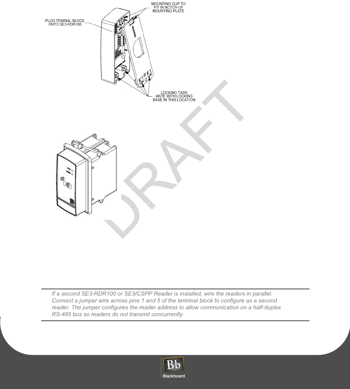
Plug the terminal block onto the SE3-RDR100.
4
Place SE3-RDR100 at an angle over the mounting plat
e, and then slide down to engage the clip onto
the mounting plate notch.
S E 3 - R D R 1 0 0 I N S T A L L A T I O N GU I D E
DO C U M E N T 1 2 9 1 R E V 0 1
P
RINTED
N
OVEMBER
24, 2009
1-7
Figure 1-7 Mounting Plate Installation - Gang Box Mount
5
Push
the bottom of the SE3-RDR100 onto the
mounting plate to lock the unit to the plate.
Figure 1-8 Single Gang Box Mount
6
Test the reader for proper operation.
7
Optionally secure the reader to the mounting plate
using the security screw supplied in the hardware
kit.
8
Apply the Security Screw Cover Decal.
IN S T A L L T H E S E 3 - R D R 1 0 0
P
RINTED
N
OVEMBER
24, 2009
1-8
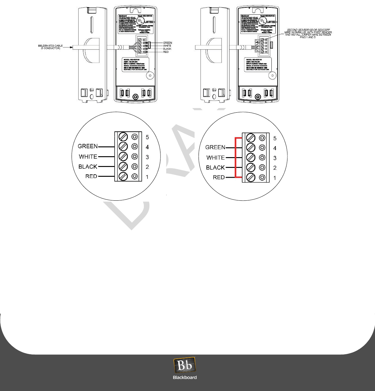
Figure 1-9 SE3-RDR100 Wiring
Jumper wire between
PINS 1 & 5
RE M O V E T H E S E 3 - R D R 1 0 0
P
RINTED
N
OVEMBER
24, 2009
1-9
R
EMOVE
THE
SE3-RDR100
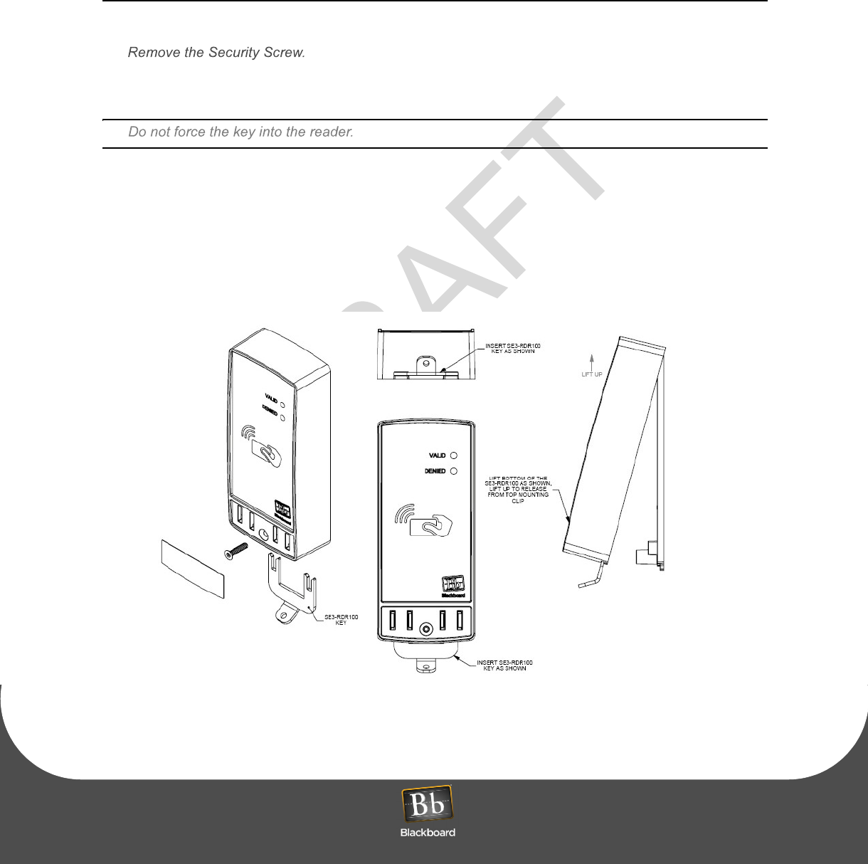
To remove the SE3-RDR100 from its mounting
1
If a security screw is installed, re
move the Security Screw Cover Decal.
2
Insert the SE3-RDR100 key into the bottom slots.
3
Gently pull the bottom of the reader at an angl
e over the mounting plate, and then slide up to
disengage the clip from the mounting plate.
4
Disconnect the terminal block.
5
Remove the wall plate from the mounting if needed.
Figure 1-10 SE3-RDR100 Mounting Removal

SP E C I F I C A T I O N S
P
RINTED
N
OVEMBER
24, 2009
1-10
SPECIFICATIONS
Physical Size:
Weight: 0.30 lbs
Input Power:
12VDC 150mA, 1.8 Watts Maximum
Operating:
Temperature: -20 to 60+ degrees Celsius
Relative Humidity: 0 to 95 percent, non-condensing
Altitude: 0 - 10,000 feet
Non-Operating:
Temperature: -20 to +70 degrees Celsius
Relative Humidity: 0 to 95 percent, non-condensing
Altitude: 0 - 35,000 feet
This device contains an integrated lithium batt
ery (BR2032). There is a risk of fire if the
battery is replaced with an incorrect type. Proper disposal of a used battery is essential.