Trio Datacom ER450-XXF01 Remote Radio Data Modem User Manual E Series
Trio Datacom Pty Ltd (a wholly owned company of Schneider Electric) Remote Radio Data Modem E Series
Contents
Users Manual Part 2
Page 31
E Series Data Radio User Manual
© Copyright 2004 Trio DataCom Pty. Ltd.
Part E Getting Started - EB450
Digital Inputs and Outputs
The EB450 provides a facility for two channels of digital user inputs
and outputs (Digital User I/O). Information on how to control and
monitor this I/O using TVIEW+ Diagnostics can be found in Part J -
TVIEW+ Management Suite - Remote Diagnostics & Network
Controller.
All user I/O is optocoupled for isolation between the EB450 and uses
equipment. When using the I/O facility the I/O electrical characteristics
and ratings must be observed. Failure to observe these ratings may
result in equipment damage.
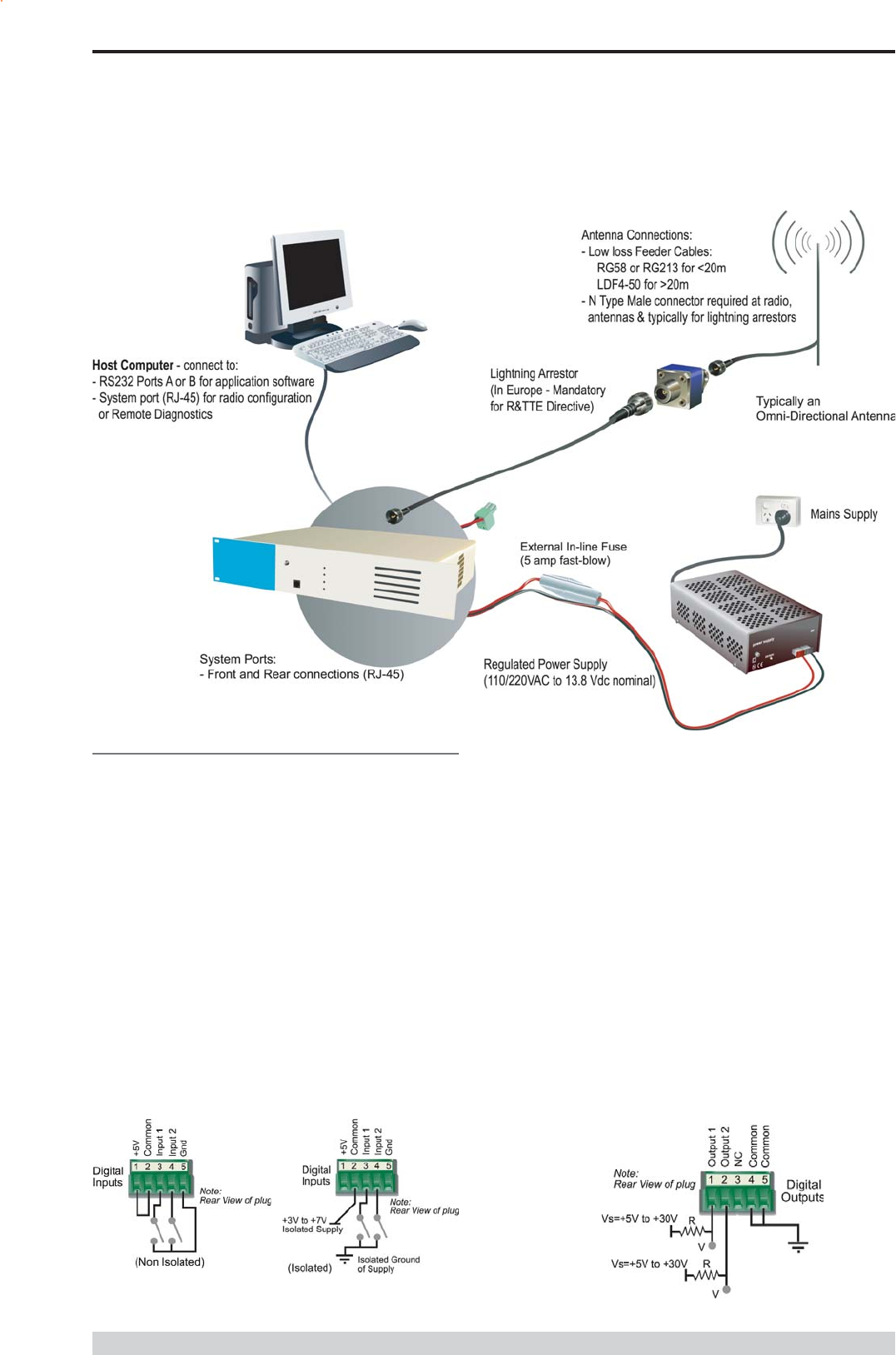
Inputs
Two User Inputs are available. They have identical interface
characteristics. Each input has an internal resistance of 470 Ohms.
Some form of switching contact (ie: switch, relay) is normally used to
change the state of the input. Both an isolated and non-isolated input
configuration is possible.
Typical Radio Setup
Is
TVIEW+ Diagnostics will recognise an input as being ON when the
switch is closed. If the switch is open (or not connected) TVIEW+
diagnostics will recognise the inputs as being OFF.
Outputs
Two User Outputs (Open Collector) are available. They have identical
interface characteristics. The maximum current allowed through each
output is 20ma. External resistors must be used keep the current
below this value.
Each output has an internal resistance of 100 Ohms.Ohms law can be
used to calculate the resistance required for a specific voltage (keeping
the current below 20mA). Nominally 1k Ohm is used for a +13v8
supply and 330 Ohms for a +5v supply.
When the OUTPUT is OFF, V = Vs. No current will flow when output
is off.
When the OUTPUT is ON, V = nominally 2.3 volts . Current is set
by resistor.
Page 32
E Series Data Radio User Manual
© Copyright 2004 Trio DataCom Pty. Ltd.
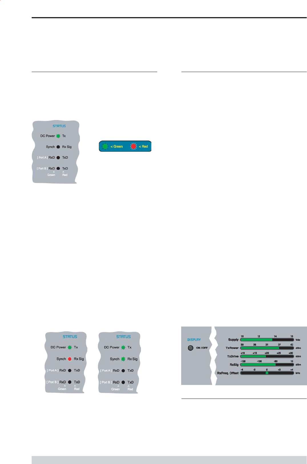
Bar Graph Indicators
The bar graph indicators on the front panel provide variable information
regarding the performance of the Base Station. To enable / disable the
bar graph display depress the Display ON / OFF button. The display
will turn off automatically after 5 minutes.
DC Supply:
Indicates the supply input voltage at the exciter module. Typically
13.8Vdc.
Indication: <10Vdc no LEDs on, 10-10.9Vdc LEDs RED, 11-
15.6Vdc All LEDs GREEN, >=15.7Vdc last LED RED.
Tx Power:
Indicates forward RF power output as measured at the TX antenna
port. Typically +37dBm.
Indication: <20dBm no LEDs on, 20-40.6dBm (11.5W) LEDs
GREEN, >=40.7dBm last LED RED.
Tx Drive:
Indicates exciter drive level. Typically +20dBm.
Indication: <10dBm no LEDs on, 10.0-25.9dBm LEDs GREEN,
>=26.0dBm last LED RED.
Rx Sig:
Indicates receive signal strength. Typically -85 to -65dBm.
Indication: <-120dBm no LEDs on, -120 to -110.1dBm LEDs RED,
>=-110dBm LEDs GREEN.
RxFreq. Offset:
Indicates offset of receiver AFC - useful in determining frequency drift.
Typically 0kHz.
Indication: Single GREEN LED to indicate current value, <-3.6kHz or
>+3.6kHz LED is RED. No signal, all LEDs OFF.
Note: 5 second peak hold circuitry.
Part E Getting Started - EB450
Test Mode
The Bar Graph indicators have a Test Mode, which cycles all LEDs
for correct operation (before returning to their normal operation). To
activate this mode, simply depress the ON / OFF button while
applying power to the unit.
Hardware Error
A hardware error is indicated on the status LEDs by all LEDs flashing
RED at a rate of 1Hz. This indicates internal communications to the
exciter inside the basestation has been lost and the base station needs
to be returned to repair.
Received Signal Indicator
The RX/SYNC LED indicates the state of the receiver.
If the LED is off, no signal is being received.
A RED indication shows that an RF carrier is being received, but no
data stream can be decoded. This will briefly happen at the very start
of every valid received transmission or may indicate the presence of
interference, or another user on the channel.
A continuous GREEN indication shows that the modem is locked and
synchronised to the incoming signal, and has excellent Bit Error Rate
(BER). Any losses of synchronisation (BER errors) are shown as a
visible RED flicker of the LED.
Note: This might only be apparent on a PTMP slave when only
receiving.
Data Flow breakout LEDs
There are also two LEDs to indicate data flow into and out of the two
user ports.
Input data to be transmitted is shown as a RED flash, and received
data to be output to the port is shown as a GREEN flash.
If data is alternately flowing in and out quickly, then the indicator
appears Orange.
LED Indicators & Test outputs
Radio is Powered
If all the LEDs are off, no power is reaching the radio modem.
Successful power-up is indicated by the PWR LED indicating a
continuous (healthy) GREEN state. Note that this LED is turned RED
when the transmitter is active.
LED Legend
Page 33
E Series Data Radio User Manual
© Copyright 2004 Trio DataCom Pty. Ltd.
EH450 Quick Start Guide
Introduction
Welcome to the Quick Start Guide for the EH450 Hot Standby Base /
Repeater Station. This section provides additional step-by-step
instructions to install, commission and operate the EH450 Hot
Standby Base Station. This document should be read in conjunction
with the EB450 Base Station Quick Start Guide.
The EH450 is a fully redundant, hot standby digital data radio base /
repeater station providing automatic changeover facilities.
The EH450 is designed as a modular solution, comprising 2 identical
EB450 base station units (standard) linked to a central, fail-safe
monitoring and changeover controller (Hot Standby Controller). Either
base station may be taken out for maintenance without the need for
any system down time. The automatic changeover is triggered by out
of tolerance (alarm) conditions based on either RF and/or user data
throughput parameters.
Part E Getting Started - EH450
Features and Benefits
Individual and identical base stations with separate control logic
changeover panel
Modules are hot swapable without user downtime
Flexible antenna options single, separate Tx & Rx, two Tx
and two Rx
Both on-line and off-line units monitored regardless of active
status
Also refer to the common Features and Benefits list of the E
Series Data Radio
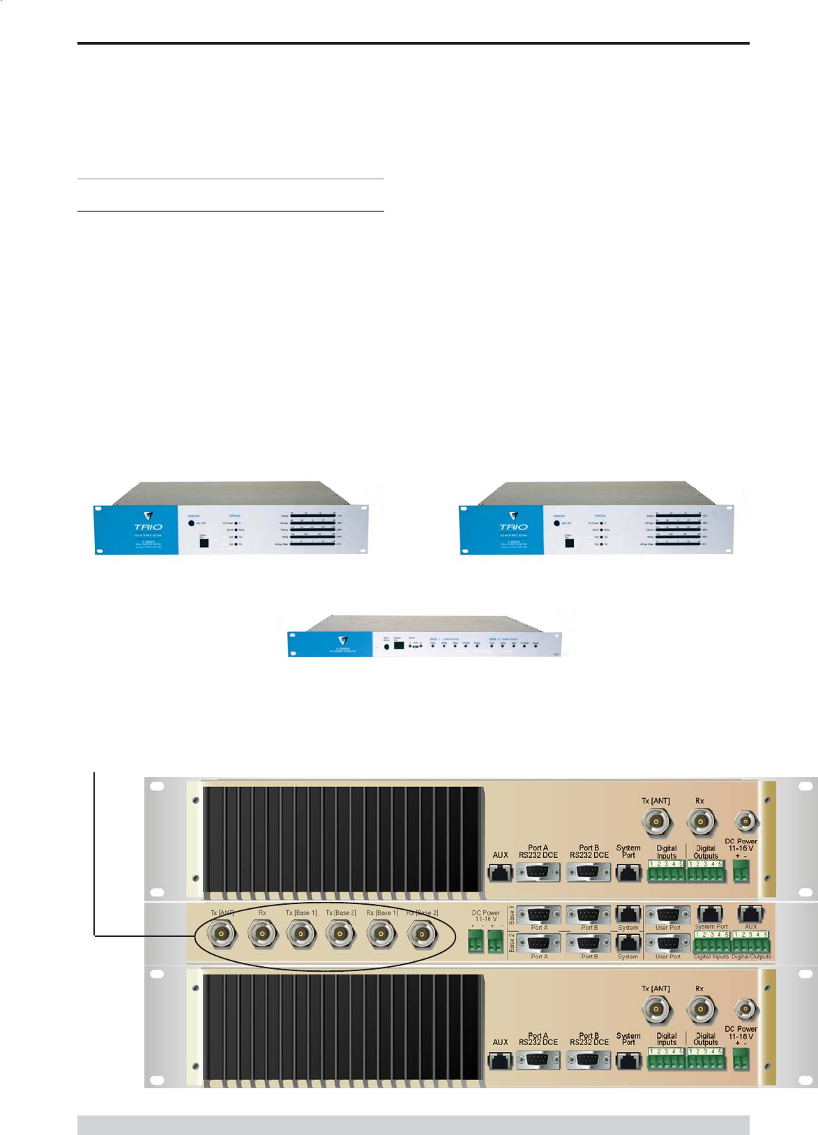
Base / Repeater Unit
Hot Standby Controller Unit
Base / Repeater Unit
Note: RF connectors not used on ETSI version
Rear View

Page 34
E Series Data Radio User Manual
© Copyright 2004 Trio DataCom Pty. Ltd.
Operational Description
The Hot Standby Controller (HSC) unit is a 1RU rack mounted
module that interfaces to two physically separate base stations (each
2RU rack mounted modules) via a number of RF and data cables.
Both base stations are operating simultaneously and both units are
constantly receiving signals, however only data from one base
station, the online base station is directed to the user equipment. The
online base station is the only base station transmitting at any time.
The Hot Standby Controller has the following functions:
Diplex the transmit and receive paths (Assuming internal
duplexer fitted), TX Only.
Amplify and split the incoming signal two ways so both base
stations receive at once.
Monitor status reports from both base stations to identify faults
and swap over the online base station if required.
Switch the antenna via internal coaxial relay duplexer to the
online base station transmitter and inhibit the offline base station
from transmitting.
Switch the User A and B data ports through to the online base
station.
An optocoupler based switch in the base station controller directs data
to and from ports A and B on the rear panel directly to ports A and B
on the on-line base station without any involvement from the Hot
Standby controller microcontrollers (apart from selecting the on-line
base). This provides protection of the system from failure of the
microcontroller.
As well as ports A and B, each base has a system port. The system
port of each base station is interfaced to the microcontroller on the Hot
Standby controller. This allows the microcontroller in charge of
selecting the base station to receive diagnostic messages from each
base station to decide their health.
The base station has its own system port on the rear panel and this is
interfaced to the Hot Standby Controller Module. The HSC will route
diagnostics at the rear panel system port to and from the system ports
of the base stations.
Warning
The base station front panel system port has priority over the rear
panel port, which is used for communication between the base station
and the Hot Standby Controller. This is to permit service personnel to
reconfigure the base station module without disconnection from the Hot
Standby Controller. It should be noted however, that when the front
panel port is accessed, a changeover event will occur due to lost
communications with the Hot Standby Controller.
Mounting and Environmental
Considerations
The EH450 Hot Standby Base Station is housed as a 5RU 19 rack
mounted set, encompassing 2 x 2RU Base Station units and 1 x 1RU
Hot Standby Controller unit. The mounting holes on the front panels
should be used to secure the units to the rack.
The unit should be mounted in a clean and dry location, protected from
water, excessive dust, corrosive fumes, extremes of temperature and
direct sunlight. Please allow sufficient passive or active ventilation to
allow the radio modems heatsink to operate efficiently.
All permanent connections are made at the rear of the unit. This
includes: Power, Antenna, Communications Ports, Digital I/O and
System Port. The front panel has an additional System Port
connection point for easy access.
The Base Station front panel system ports must not be used while in
this configuration.
Part E Getting Started - EH450
Page 35
E Series Data Radio User Manual
© Copyright 2004 Trio DataCom Pty. Ltd.
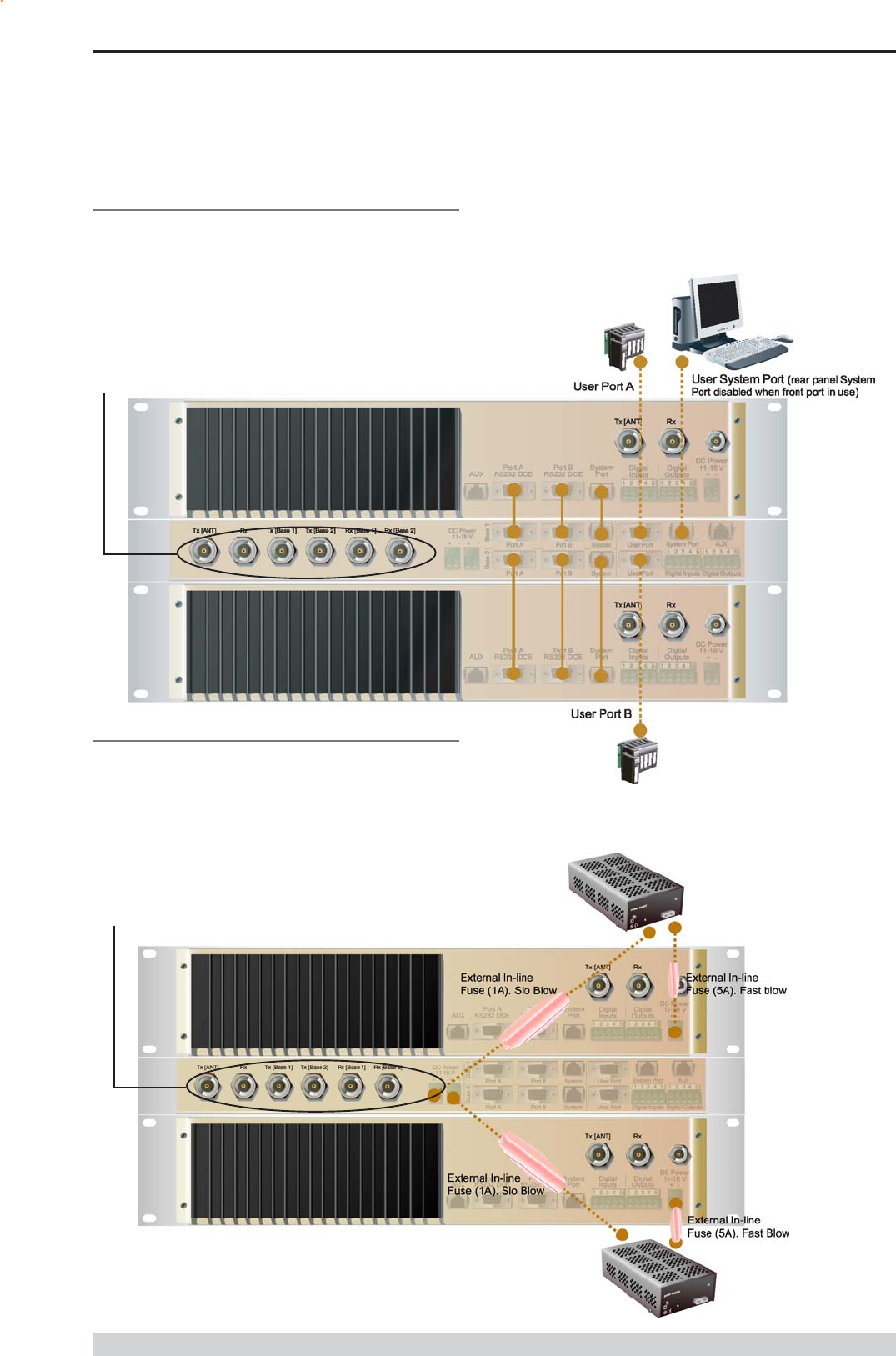
Communications Ports
The A & B Data Ports and System Ports of each Base Station
connect directly to the Hot Standby Controller units corresponding
ports with the cables provided. Ensure all clamping screws on the
Data Port cables are firmly secured and the System Port cables are
clipped in correctly. See figure below for further details.
Note: Only the front or rear User System Port can be used at any
one time on the Hot Standby Controller.
Power Supply and Protection
The EH450 has facilities for dual power supplies to provide for a
redundant system. A separate power supply should be used for each
of the Base Station units. The Hot Standby Controller unit has
connections for dual power supplies and it is recommended that the
power supplies from each of the Base Stations also be used to power
the Hot Standby Controller unit. See Figure below for further details.
See ER450 Quick Start Guide Section for detailed wiring information.
The Hot Standby Controller units A & B Data Ports connect directly to
you application device and the System Port connects directly to your
local PC. See ER450 Quick Start Guide Section for further details.
Part E Getting Started - EH450
Note: RF Connectors not used on ETSI version
Note: RF Connectors not used on ETSI version
Page 36
E Series Data Radio User Manual
© Copyright 2004 Trio DataCom Pty. Ltd.
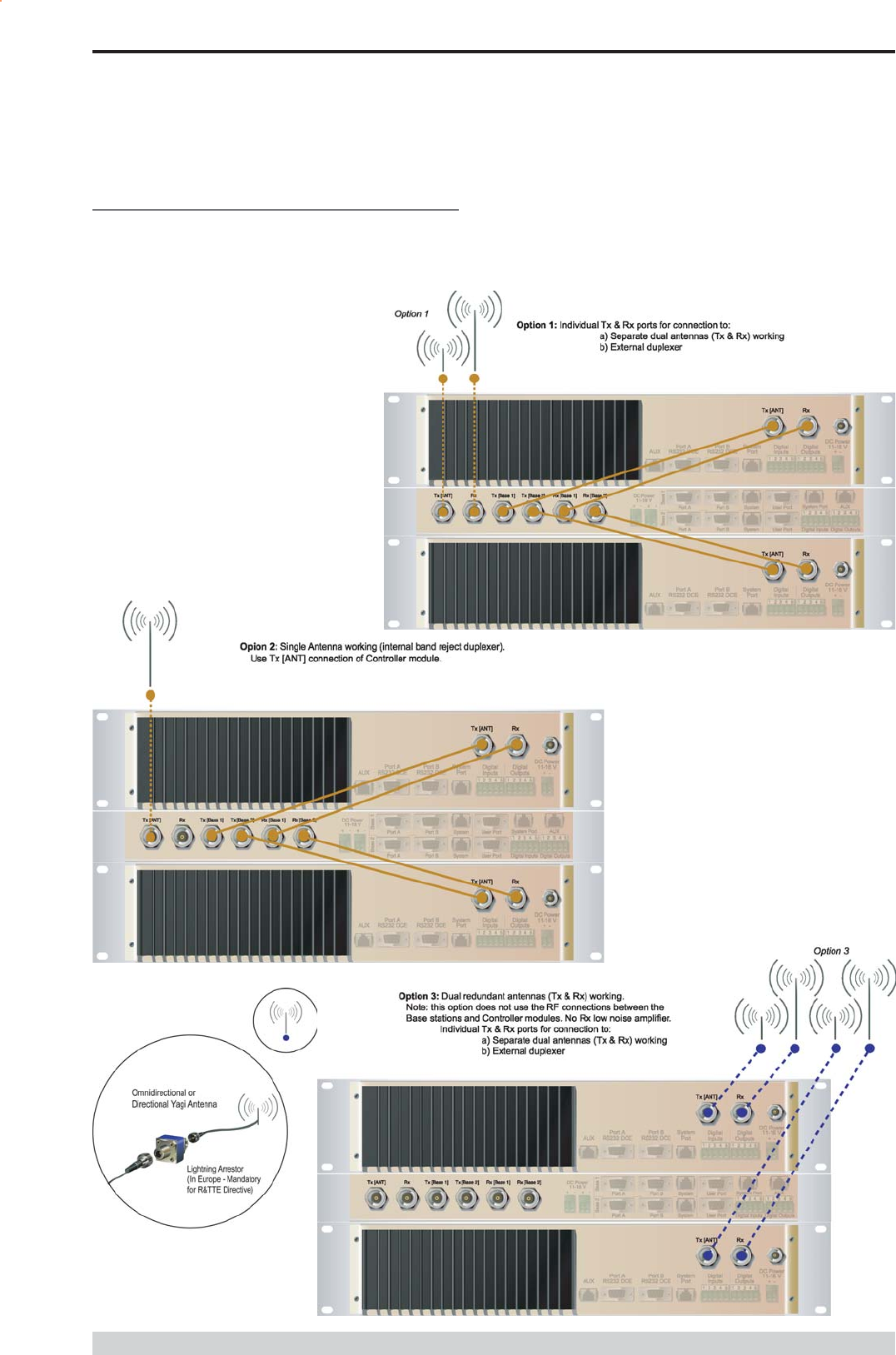
Connecting Antennas and RF Feeders
There are 3 primary antenna connection options. All connectors used
are standard N Type sockets. See figures below for further details.
See ER450 Quick Start Guide for detailed wiring information.
Part E Getting Started - EH450

Page 37
E Series Data Radio User Manual
© Copyright 2004 Trio DataCom Pty. Ltd.
Front Panel Operation
Switches
Select Switch
The 3 position switch (1 / Auto / 2) on the front panel provides the
following functionality:
Position 1: base station 1 is forced into operation
Position Auto: changeover hardware will select the online base
station
Position 2: base station 2 is forced into operation
The select switch is also used to identify the target base station for
configuration programming.
Adjacent to the select switch are two LEDs: These LEDs indicate the
current active base station.
Select LEDs
Green - Auto Mode
Red - Remote Force
Amber - Local Force
2 Green Firmware Download
2 Amber Test Mode
2 Red Fatal Error - refer User Manual
Reset Switch
This is a momentary close switch which when depressed will reset all
LED alarm indications.
System Port
There are two system port connection points, one on the rear panel
and one on the front panel. Both have the same functionality and can
be used for local diagnostics, firmware front panel downloads and hot
standby controller testing. To access the system port use the
diagnostic/programming cable supplied.
Note: When connection is made to front panel system rear system
port is disabled.
Alarm Status LEDs
There are 10 alarm LEDs on the front panel, five for base 1 and five for
base 2. These LEDs provide a general indication of base station
status. More detailed base station status information is available by
using the diagnostic utility software.
The indicated alarms for each base station are:
Freq. => Frequency Error
RxSig => Receive Signal (RF) Error
Data => Receive Data Error
TxPower => Transmit Power (RF) Error
Supply => DC Voltage Error
The status of each alarm is represented as follows:
OFF => Unknown
Green => No Error
Red => Current (active) Error condition
Amber => Recovered Error condition
Any active or recovered error LEDs will turn to green after the reset
alarms switch has been pushed or remotely reset.
Part E Getting Started - EH450

Page 38
E Series Data Radio User Manual
© Copyright 2004 Trio DataCom Pty. Ltd.
Part F - Operational Features
Multistream functionality (SID
codes)
The E Series sends data messages in packets. A feature of the E
Series is that an address can be embedded in each packet. This
address is called the stream identifier code (SID).
By configuring a user serial port for a specific SID code, it is
possible to steer messages to similarly configured ports between
radio modems. In effect, it is possible to use the multiple serial
ports available on the E Series, to enable multiple protocols to
share the same RF channel. The SID codes also facilitate the use
of other features such as TView diagnostics. Unique selective
routing, repeating, and data splitting functions available in the radio
modems configuration allow data steering and bandwidth
management in complex systems.
See Part I - TView+ Management Suite - Programmer and Part J -
TView Remote Diagnostics and Network Controller for details.
Collision Avoidance (digital and
RFCD based)
Where multiple unsynchronised protocols coexist on a common
multiple access radio channel, there is always a possibility that
both hosts may poll different remote devices at the same time. If
both devices attempt to answer back to the single master radio at
the same time, it follows that a collision could occur on the radio
channel.
To facilitate the operation of multiple protocol operation on the
radio channel, a transparent collision management system has been
implemented : See Part I - TView+ Management Suite - Programmer
for details.
Digital Collision Avoidance System
If the multiple access master has been configured for full duplex
operation, it is possible to use the inbuilt collision avoidance signalling
system.
Once the master radio receives a valid incoming data stream from a
remote, a flag within the outbound data stream is used to alert all
other remote devices that the channel has become busy. Remote
devices wishing to send data will buffer the message until the channel
status flag indicates that the channel is clear. A pseudo-random timing
value is added to the retry facility to ensure that waiting remotes do not
retry at the same time.
RF Carrier Detect RSSI based Collision
Avoidance
In half duplex systems, the receivers RF carrier detect is used to
inhibit the transmitter whilst a signal is being received.
Digipeater Operation
A feature of the E Series radio modems is the ability to internally
repeat data packets to provide stand alone repeater facilities
without the need for external intelligence.
This is done by programming SID Codes to Repeat a stream or
range of streams. Wizard templates can be used to simplify setup
of this and other features.
See Part I - TVIEW+ Management Suite for details.
TVIEW+ Diagnostics
The E Series has an inbuilt remote configuration and diagnostics
utility.
This facility allows transparent remote access to the key
configuration and operating parameters of the radio.
See Part J - TView Remote Diagnostics and Network Controller for
details.
Part F Operational Features
Poor VSWR Sensing
To protect the transmitter, forward and reverse power are measured on
each transmission.
If a VSWR of 3:1 or greater is measured, transmitter output power is
reduced to +31 dBm.

Page 39
E Series Data Radio User Manual
© Copyright 2004 Trio DataCom Pty. Ltd.
Part G Commissioning
Check DC power connector for correct voltage (10-16VDC) and
polarity, BEFORE plugging in the power connector.
Power-up
Upon power up, the radio will self test and shortly after the green
power LED will be displayed.
Failure of the power LED to light indicates no power, or failure of the
fuse due to incorrect polarity or over-voltage.
Other failure such as fatal internal errors will initiate error modes as
detailed in Part E - Getting Started: LED Indicators and Test Outputs.
LED Indicators
Will depend on the system architecture. If the device is a remote site
receiving a base station with a constant carrier, then the RXSIG/
SYNC LED should be green to indicate healthy reception of the
wanted signal.
If the site has been configured as a constantly transmitting base station,
then the PWR/TX LED should show red.
In other types of systems, TX and RX bursts would be indicated by
the RX or TX LEDs as above.
Data flow to and from the user ports is indicated by the TXD/RXD
LEDs for each port.
(See Part E Getting Started: LED Indicators and Test Outputs.)
Data Transfer Indications
Bi-colour LEDs are provided to indicate RS232 data being transmitted
and received on each data port. A RED flash indicates a byte (or
bytes) of incoming data from the serial line which will be transmitted to
air, and a green flash indicates a byte of data received off air being
released onto the serial line.
If data is being sent to the radio modem and the Data LED does not
flash RED, this may indicate a wiring or configuration problem. Check
that the TX and RX data lines are correctly wired (see Part E Getting
Started: LED Indicators and Test Outputs).
Also check that character set and parity settings (i.e. N,8,1 etc) are set
identically at the terminal and the radio modem. Note that some
incorrect settings of the character set parameter can still produce
transmittable data, even though the data will not be understood by the
application.
Antenna Alignment and RSSI
Testing
Once the RXSIG LED is lit, it is possible to confirm RX signal strength
and align a directional antenna by monitoring the RSSI output.
This DC voltage appears at Pin 9 of Port B.
A ground reference can be obtained from chassis ground or Pin 5 of
Port A or B.
The chart below shows Pin 9 voltage as it relates to signal strength.
Part G Commissioning
Link Establishment and BER
Testing
Once communications has been established, it is possible to confirm
the packet error rate performance of the radio path, and thus estimate
the BER figure.
There are a number of tools provided to do this. The easiest is to use
the indicative packet error test provided within the TVIEW+
Diagnostics under statistical performance tools. Alternatively, it is
possible to use hyper terminal, or other packet test instruments or PC
programs to run end to end or perform loopback testing.
Please note that when using a loopback plug some understanding of
the packetising process is necessary, since each test message must
be carried in a single packet for meaningful results to be obtained.
Note also that in PTMP systems, allowance must be made for
collision potential if other data is being exchanged on the system.
VSWR Testing
VSWR testing is achieved using specialized VSWR testing
equipment, or a Thruline power meter that measures forward and
reverse power.
VSWR is the ratio between forward and reflected transmitter power,
and indicates the health and tuning of the antenna and feeder system.
VSWR should be better than 3 to 1, or expressed as a power ratio,
<6dB or no more than 25%. To activate the radios transmitter for
VSWR testing, use:
a) An RTS loop
b) A system port PTT plug
Analog RSSI Output Characteristics - E Series Data Radio
0
0.5
1
1.5
2
2.5
3
3.5
4
4.5
5
-120 -110 -100 -90 -80 -70 -60 -50 -40
RF Level (dBm)
RSSI (DC Volts)

Page 40
E Series Data Radio User Manual
© Copyright 2004 Trio DataCom Pty. Ltd.
Part H Maintenance
Routine Maintenance
Considerations
The E Series hardware itself does not require routine maintenance.
However all radio products contain crystal frequency references, and
the stability of these crystals changes with time. The effect of this is
that the product will slowly drift off frequency, and eventually it will
require re-calibration. E Series radios are designed with high quality,
low drift specification references, to ensure a long maintenance free
lifespan. The length of this lifespan will depend on the severity of
temperature extremes in the operating environment, but is normally 3
5 years. Extended frequency drift can be detected using TVIEW+
Diagnostics Freq error parameter.
Generally, re-calibration is achieved by replacing the radio in the field
with a spare, and returning the radio to a service centre for re-
calibration and specification testing at moderate cost.
Routine maintenance should be performed on external equipment
subject to greater environmental stresses including antennas, RF
feeder cables, backup batteries and cooling fans (if required). This
maintenance should include testing of site commissioning figures such
as received signal strength, VSWR, P/S voltage etc.
Part H Maintenance

Page 41
E Series Data Radio User Manual
© Copyright 2004 Trio DataCom Pty. Ltd.
SECTION 2
Part I TVIEW+ Management Suite -
Programmer
Part J TVIEW Remote Diagnostics and
Network Controller
Part K Appendices
Part L - Support Options
SECTION 2 TVIEW+ Management Suite

Page 42
E Series Data Radio User Manual
© Copyright 2004 Trio DataCom Pty. Ltd.
Part I TVIEW+ Management Suite - Programmer
Part I TVIEW+ Management Suite -
Programmer
Introduction
This manual covers the installation and operation of the E Series
TVIEW+ Management Suite which incorporates 3 utilities:
Programmer for configuration of the radio RF parameters,
system parameters and data ports
Diagnostics* for real-time monitoring and logging of radio
performance parameters
Firmware Update for loading new firmware releases into the
radio data modem
All utilities can be run on any IBM compatible computer running
Windows 95® and above. This section describes use of the
programmer and firmware Update utilities in detail. Users should refer
to the separate Diagnostics section for information about this utility.
The programmer is used to set configuration parameters within the
ER450 data radio modem and EB450 base station. The utility permits
configuration of modems connected directly to the PC as well as over
the air to a remote unit. Configuration parameters can be saved to a
disk file for later retrieval, or used for clone programming of other
modems.
All configuration parameters are held in non-volatile memory
(NVRAM) on the Data Radio Modem. Configuration is fully
programmable via the Systems Port using the programming adaptor
and cable supplied. Disassembly of the unit is not required for any
reason other than for servicing.
The diagnostics utility permits monitoring and logging of radio
performance parameters for both E Series* as well as D Series* data
radio modems and base stations. It supports homogeneous systems
of radios as well as mixed systems of both E and D series radios.
The firmware update utility permits field upgrade of the firmware in an
ER450 data radio modem, EB450 base station and EH450 hot
standby unit connected directly to the PC. A special serial adaptor
cable is required to be connected to Port B to load firmware into the
unit.
* Requires the optional DIAGS Network Management and Remote
Diagnostic Facility to be installed - per radio.
Installation
Unit Connection
Programmer and Diagnostics Utilities
The unit is connected to the PC using the supplied DB9-RJ45 adaptor
cable (part no. TVIEW+ Cable) for local configuration changes or
diagnostic monitoring. The cable should be connected to the RJ45
System Port of the unit and a valid PC serial port (e.g. COM 1) DB9
connector.
(See Part E - Getting Started: Communications Ports)
Firmware Update Utility
The unit to be updated with firmware connects to the PC using the
DB9-DB9 adaptor (part no. DRPROG). The cable should be
connected to the DB9 Port B connector on the unit and a valid PC
serial port (See Appendix C for details) DB9 connector.
Software
Please take a moment to read this important information before you
install the software.
The installation of this Software Suite is a 2 step process.
Step 1 completes the typical installation of the TVIEW+ Management
Suite and will install the Programming Software together with the E
Series Documentation.
Step 2 installs the Diagnostic Software and is optional. This step is
only required if your radios have Remote Diagnostics enabled.
STEP 1: Installation - TVIEW+ Management
Suite
Note: If a previous version of the TVIEW+ Management Suite has
been installed on your PC, you must uninstall it via Control Panel
Add/Remove Programs.
Close down all other programs currently running.
Place the CD-ROM in the drive on the PC.
Using Windows Explorer locate the files on the CD-ROM.
In Windows Explorer double click on the file called
TVIEW+_(Version#)_install.exe
After the installer starts follow directions.
Page 43
E Series Data Radio User Manual
© Copyright 2004 Trio DataCom Pty. Ltd.
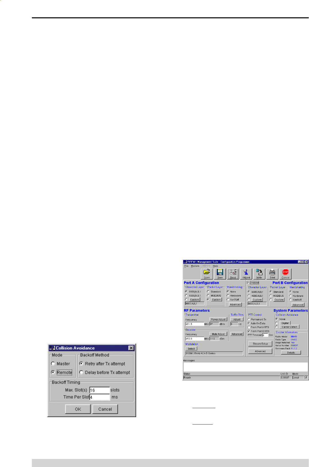
Programmer
Main Window
When first started the programmer is in file mode as indicated by the
mode field at the bottom right of the panel shown below. In this mode it
is possible to open a previously saved configuration file, or configure
various programming options and save the configuration to a file.
Note: Modulation type is not available in this mode.
To commence programming a unit (radio remote or base station) a
session must first be established by using the READ function. This
function reads the current configuration from the unit and displays it in
the main window. The mode displays changes to local or remote
depending on the type of session selected at the read function. Several
options in the main window may be blanked out until a session has
been established with a unit.
Note: Changing any item on the menu will in general not take effect
until data is written back to the unit using the WRITE function.
The procedure to follow for normal programming of unit is:
Read unit
Configure parameters (or Open a previously saved
configuration file)
Write unit
Several modems of the same radio type can be programmed with the
same configuration using the clone facility described in Clone Mode. It
is important to note that when using this facility the cloned radio should
be of the same type to ensure it does not operate outside its capability.
Part I TVIEW+ Management Suite - Programmer
STEP 2: Installation - TView Diagnostic
Software (Optional)
Note: If a previous version of the TView WinDiags software has
been installed on your PC, you must uninstall it via Control Panel
Add/Remove Programs.
Close down all other programs currently running.
Place the CD-ROM in the drive on the PC.
Using Windows Explorer open the Diagnostics directory on
the CR-ROM.
Double click on the file called setup.exe
After the installer starts follow directions.
Other:
The current E Series Manuals are supplied and installed as part of the
TVIEW+ Management Suite installation in Adobe Acrobat format.
Adobe Acrobat Reader is provided on the CD-ROM for installation if
required.
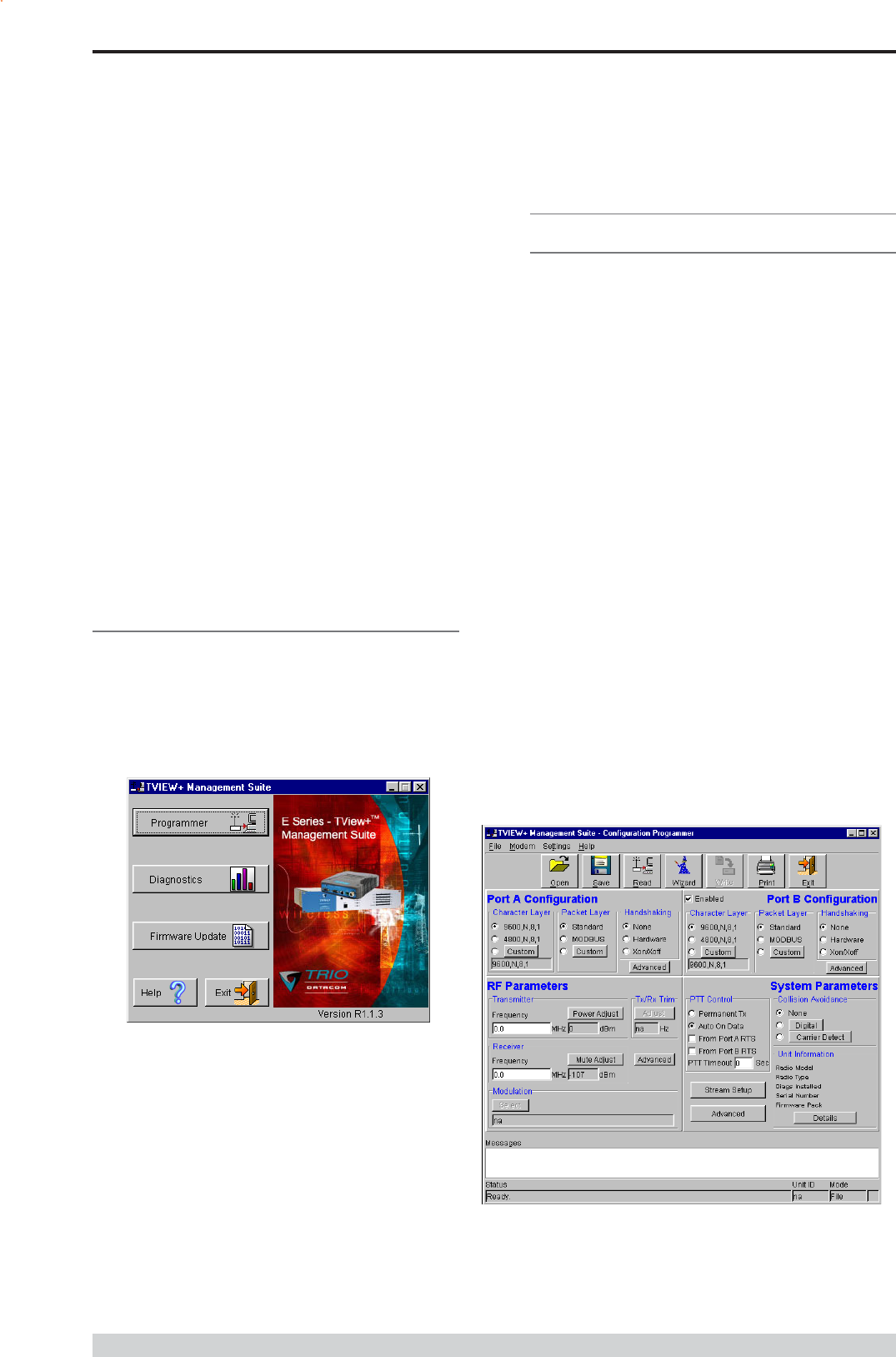
TVIEW+ Front Panel
When started the TVIEW+ front panel appears. The larger buttons
permit each of the three utilities to be started. The diagnostics button
may be greyed out if this utility has not been installed or found in the
correct file directory. Access to local help and an exit facility are
provided by the remaining 2 buttons.
Page 44
E Series Data Radio User Manual
© Copyright 2004 Trio DataCom Pty. Ltd.
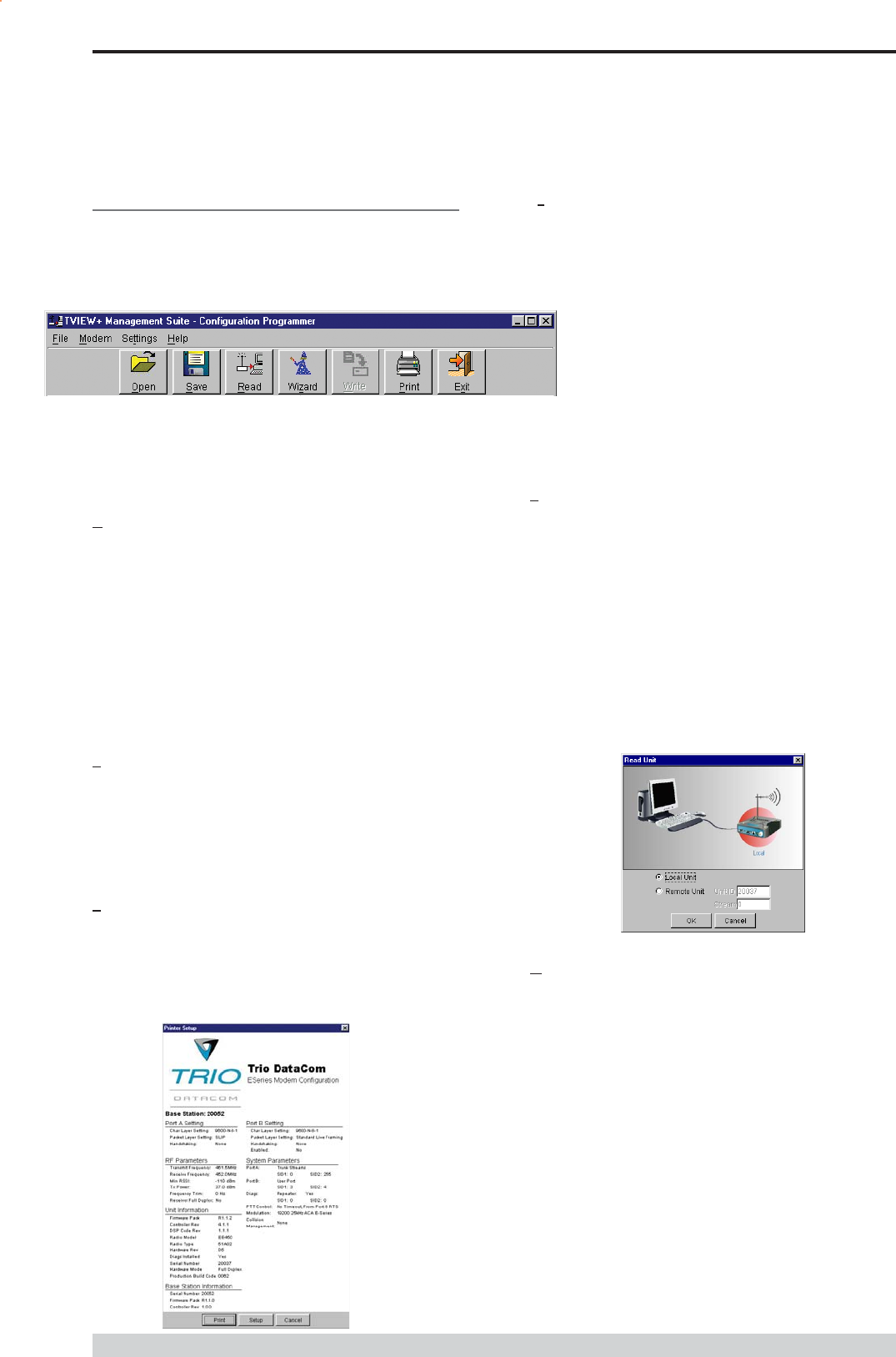
Pull Down Menus and Toolbar Buttons
The items on the pull-down menus can be selected either directly with
a mouse or using the ALT key in combination with a HOT KEY (e.g.
ALT-F to select the file menu). Several of the functions within each
menu are also available on the toolbar (click once to select).
File Menu
The file menu allows the user to load (open) or save configuration data
as well as to quit the program. The files are saved with an .cfg file
extension
Open (also available on the toolbar)
This function is used to load an existing configuration file that can be
used to directly program the radio or to use as a starting point to edit
configuration parameters. Note that a session must be established
with the unit by initially reading the configuration parameters from the
unit prior to being written to a unit.
If in file mode the modulation type will not be displayed. If in local/
remote mode and a file that was saved from local/remote mode is
opened, then modulation type will be imported and used, but only if it
is valid for the connected hardware. If not, then the units read
modulation type will be used.
Save (also available on the toolbar)
This function is used to save the current configuration parameters to a
file for future recall.
If in file mode only basic RF, Port and System parameters are
saved and re called. If in local/remote mode then modulation type is
saved and re called.
Print (also available on the toolbar)
This function prints out the configuration data to the default printer in a
standard format. There are no options for this item.
This should be used if a complete record is required for site/unit
configuration. Firmware/Modulation/Diags/Hardware type are all
printed.
Exit (also available on the toolbar)
This function terminates the program. The user is requested to confirm
this selection before exiting the application.
Modem Menu
This radio menu allows configuration data to be read from and
written to the unit (remote radio or base station) using the
selected PC serial port connection (see Settings menu). The
action of reading the configuration establishes a session with the
unit. Communications is maintained with the unit to ensure that
the session remains open. If the session has been lost due to
data transmission errors or disconnection of the programming cable it
will need to be re-established to ensure any updated configuration is
written successfully to the unit.
Read (also available on the toolbar)
This function establishes a session with the unit, reads configuration
data from the unit and displays it in the programmer main window.
When selected a dialogue window appears prompting the user to
choose whether the unit to read is local (connected directly to the serial
port or remote (connected over the air to the unit connected to serial
port). Unit no. (Serial no.) must be entered and the stream SID code is
on (default =0)). After configuration data is read from the unit it is
available for editing and writing back to the unit or saving to a file. The
progress of data transfer to or from the unit is indicated by a message
window as well as a rotating indicator in the bottom right hand corner
of the main window.
Write (also available on the toolbar)
This function writes configuration data displayed in the main window to
the unit and reboots the unit. When selected a dialogue window
appears prompting the user to confirm whether to proceed. A progress
indicator in the bottom right hand corner of the main window is
displayed while data is being read. This selection is only available if a
session has been previously established and maintained with the unit.
Part I TVIEW+ Management Suite - Programmer
Page 45
E Series Data Radio User Manual
© Copyright 2004 Trio DataCom Pty. Ltd.
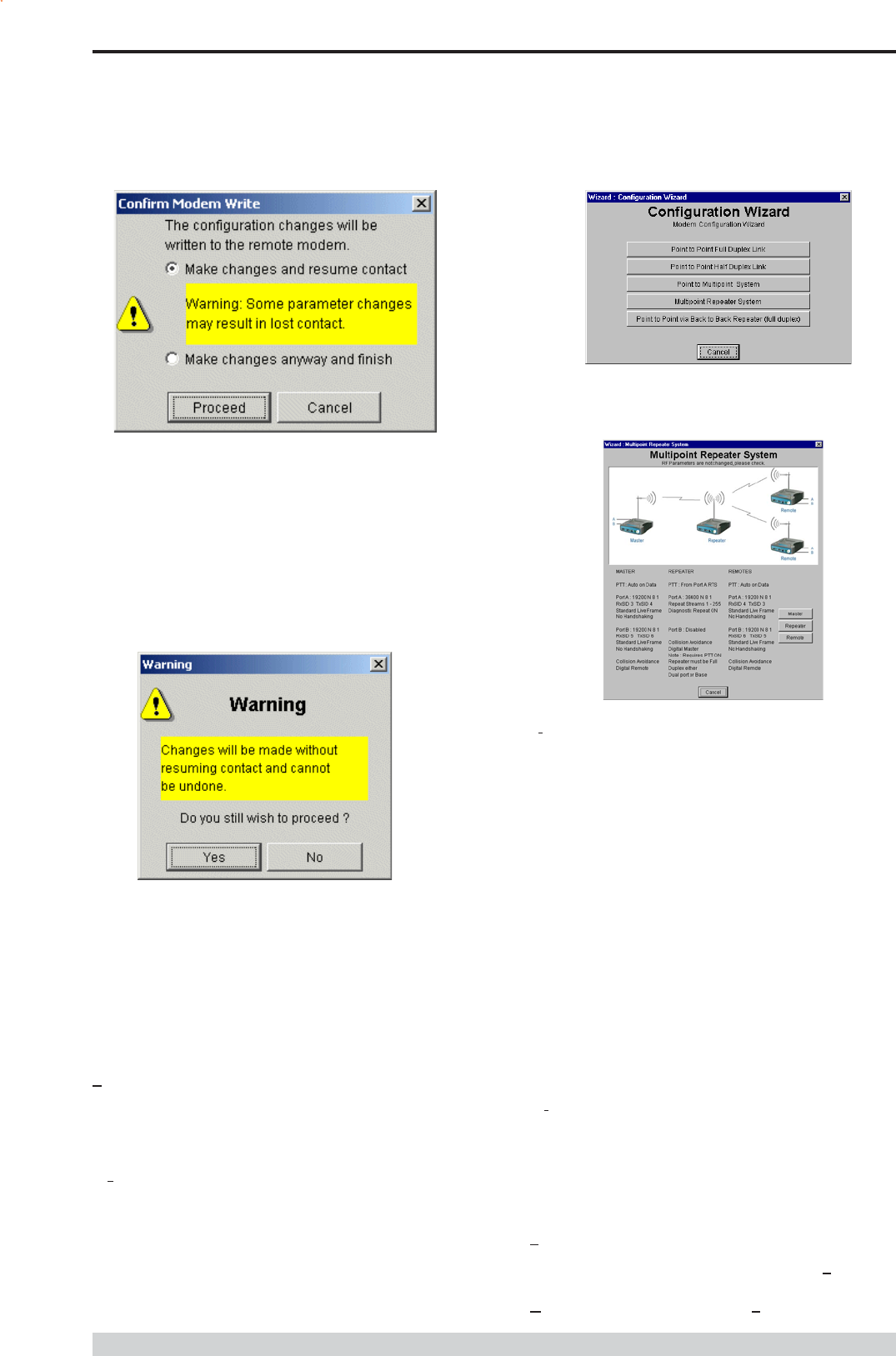
This dialog provides a facility for reversing any remote configuration
changes that cause unexpected results resulting in the device
reverting to previous configuration if contact is lost.
Choose Make changes and resume contact to safeguard changes.
Some parameter changes (such as frequency change) will, by
definition, automatically result in lost contact.
Choose Make changes anyway and finish to complete intentional
changes which will result in lost contact.
Part I TVIEW+ Management Suite - Programmer
After configuration data has been written, the session with the unit is
closed and the programmer reverts to file mode.
Note: In general, any change made on the programmer screen must
be written to the unit (using the write function) to become
permanently stored. However, changes to Power adjust, Mute adjust
and 7x/Rx trim take immediate effect to allow test and adjustment
prior to permanent storage via the write function.
Cancel Session (also available on the toolbar)
This function closes the session with unit and puts the programmer
back into file mode. All configuration changes are discarded including
changes to Power Adjust, Mute Adjust and Tx/Rx Trim.
Wizard (also available on toolbar)
This function permits the user to select standard configurations after the
configuration from a unit has been read or a file opened.
The user is prompted via a series of dialogue windows to select the
desired configuration that can then be written to the unit (remote radio or
base station).
Clone Mode
This function permits writing of the same configuration data to several
units. This feature is normally used for configuring data radio modems
connected locally.
The procedure is:
Read the configuration from the first unit.
Configure the parameters (or open a previously saved
configuration file).
Select Clone Mode (Modem menu).
Write the configuration to the first unit.
The changes will take effect when unit is repowered.
Connect the next unit.
Write the next unit which establishes a session and recognises
the unit serial number and type, which then configures the unit
Repower the unit for changes to take effect
Repeat the last 3 steps for the remaining units.
Settings
This menu permits selection of the PC serial port (COM1 to COM4)
to be used for communications with the unit. COM1 is the default
selection and if a different port is to be used it must be set before
establishing a session by reading the configuration from a unit. Whilst
a session is established with a unit this menu can not be accessed.
Help
This menu permits selection of help information using the Contents
key. Warnings regarding use of the programmer software using the
Warnings key and version detail using the About key.
Page 46
E Series Data Radio User Manual
© Copyright 2004 Trio DataCom Pty. Ltd.
Part I TVIEW+ Management Suite - Programmer
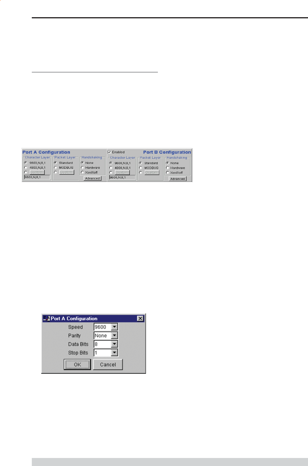
Port A and Port B Configuration
Data from these two user ports is multiplexed for transmission over the
air. Each port can be configured separately for the Character layer
(Data speed, number of data bits, number of stop bits, parity), Packet
layer and Handshaking (flow control). Port B must be enabled if
required by setting the check box at the top of its configuration section.
If Port B is off, the 16K memory is split equally between Port A Rx/
Tx buffers (i.e. 8K & 8 K). If Port B is on, then the 16K is split equally
across Port A & B Rx/Tx buffers (i.e. 4K, 4K, 4K & 4K).
The following description is common to both ports.
Character Layer
There are two standard formats and a custom format that can be
selected by checking the appropriate control button to the left of the
description. The standard formats are:
9600,N,8,1 (data speed = 9600 bps, no parity, 8 data bits, 1
stop bit)
4800,N,8,1 (data speed = 4800 bps, no parity, 8 data bits, 1
stop bit)
A non-standard format can be selected via the Custom button that
displays a dialogue box to permit selection of data speed, parity,
number of data bits and stop bits. Once selected the OK button should
be used to complete the selection. The custom selection is also
displayed in the main window below the Custom button.
Packet Layer
There are two standard configurations and a custom configuration
which can be selected by checking the appropriate control button to the
left of the description. There are essentially two basic modes of
operation for the packet assembler and disassembler (PAD).
The first is where the PAD operates in a standard mode with data
received at the port being immediately sent over the radio channel.
The second is a store and forward or delayed mode where whole data
packets are received from the port before being sent over the radio
channel.
In both cases data is sent over the radio channel in variable
length frames and delineation of these frames is dependent on
the configuration selected as well as the characteristics of the
data stream received at the data port.
The packet layer configuration options which can be selected
are:
Standard (live framing)
With standard live framing data received from the host by the modem
is immediately placed into a frame and transferred onto the radio
channel.
This avoids placing store and forward delays in the data
transmission.
If a stream of characters is received by the modem, then several
characters at a time may be placed into the same frame. The number
of characters in the frame depends mainly on the respective baud
rates of the user port and the primary channel baud rate of the modem,
as well as the level of overheads experienced on the radio channel
and the user data stream.
For example a constant stream of 300 baud user data placed onto a
9600 baud channel will result in 1 character per frame being
transmitted. If the user baud rate was lifted to 9600,N,8,1 with a
continuous data stream, then the frame size would settle to about 16
characters plus 32 overhead bits. If collision avoidance is enabled as
master the average frame size will increase to 32 characters plus
overhead bits.
The number of data bits associated with the user data stream will also
have an effect on the average size of a frame. For instance the
number of stop bits, and number of data bits per character.
The system designer must choose the best compromise of all the
above items to ensure the most efficient method of data transmission.
Note: The first character is always packetised and sent by itself
regardless of all the above variables.
Page 47
E Series Data Radio User Manual
© Copyright 2004 Trio DataCom Pty. Ltd.
Modbus
This selection configures the PAD driver with options automatically set
to implement the MODBUS protocol, e.g. 5 mSec timer.
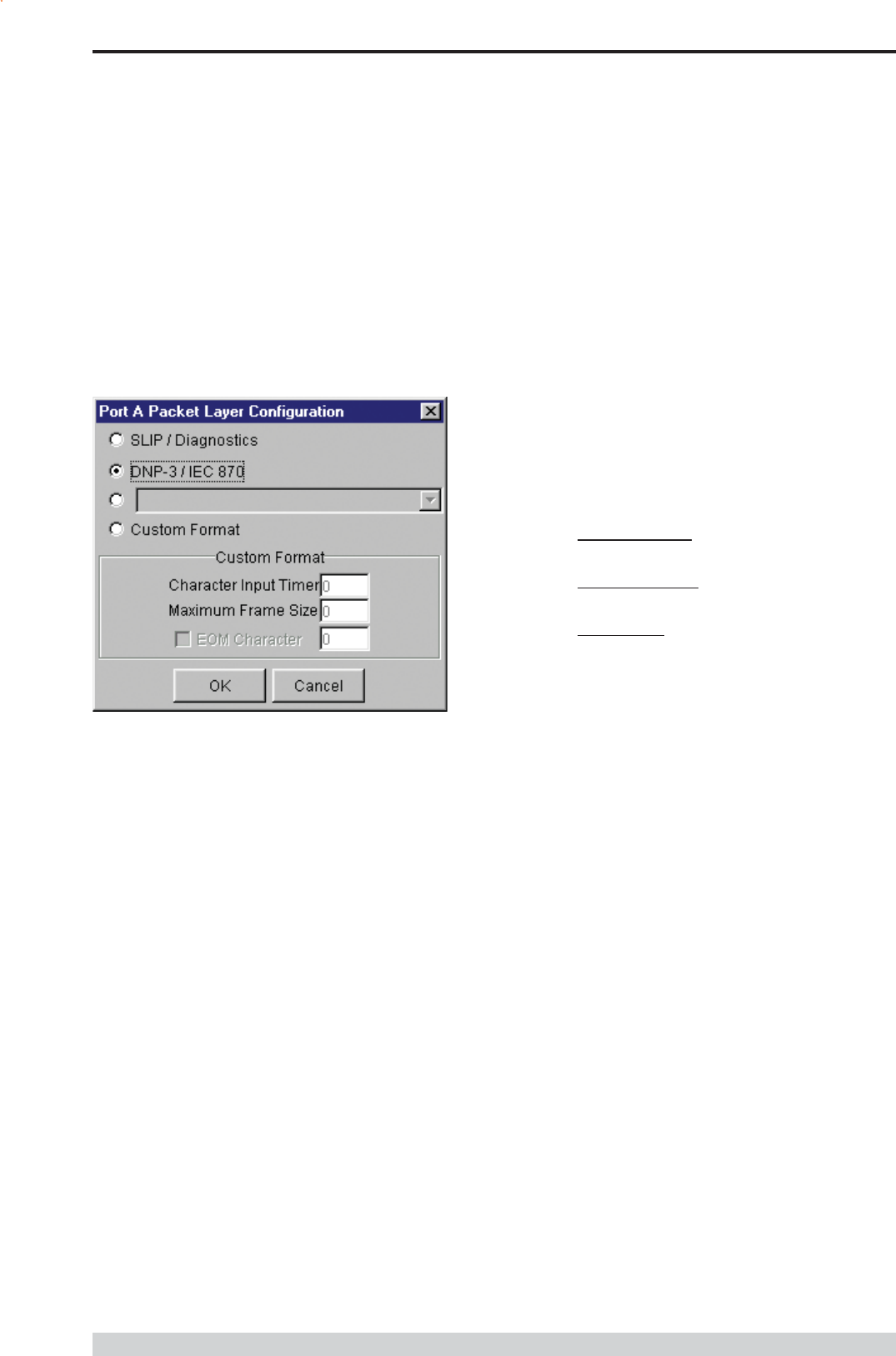
Custom
Other configurations of the PAD driver can be selected via the Custom
button which displays a dialogue box to permit selection of several
configuration options as follows:
SLIP / DIAGNOSTICS
Handshaking
If the standard PAD is selected (i.e. any settings apart from SLIP/
Diagnostics), then flow control can be either hardware handshaking,
XON/XOFF protocol or none.
The XON/XOFF flow control is not possible when using either the
SLIP/Diagnostics protocol.
The Handshaking section of the screen allows the selection of either of
the handshaking methods as well as allowing handshaking to be
disabled.
Details of the two handshaking methods are given below.
Hardware
The modem acts as Data Communications Equipment (DCE) and
supplies to the host controller the following interface signals:
Data Set Ready (DSR)
Data Carrier Detect (DCD)
Clear To Send (CTS)
Receive Data Output (RXD)
The host controller must act as Data Terminal Equipment (DTE) and
supplies to the modem the following interface signals :
Data Terminal Ready (DTR)
Request To Send (RTS)
Transmit Data Input (TXD)
DCD
DCD has several modes of operation. It is set to TRUE when
data is being transferred from the modem to the host - RXD line
active. The signal is asserted approximately 500ms before the
start bit of the first character in the data stream and remains for
approximately 1 character after the last bit in the data stream. The
other modes of operation are dependent on the advanced
settings.
Part I TVIEW+ Management Suite - Programmer
SLIP is a well known protocol for transferring binary data
packets over a data link. Each data packet is delineated by
<FEND> characters, and a substitution mechanism exists that
allows these characters to be included in the data packet.
Appendix B describes the SLIP protocol which is used
extensively in UNIX based systems, and is closely
associated with TCP/IP networks.
The diagnostics controller package uses the SLIP protocol to
communicate between base station and remote modems.
DNP-3 / IEC870
This selection configures the PAD driver to implement the DNP-3
Protocol and IEC870 Protocol.
Pull Down Menu Selection
The PAD driver can be configured for a number of vendor
specific protocols by selecting the desired option.
Custom Format
This selection permits PAD driver to be configured in a variety of
ways and requires a greater understanding of the system design.
For the modem to successfully transmit its packets (or frames) of
data over the radio channel, it must be told on what basis to
delineate data packets received at the data port. Once the end of
a data packet has been received at the port the data frame is
closed and transmission over the radio channel commences.
Delineation of data packets can be configured to occur via any
combination of:
A pre-defined minimum time delay between packets received
at the port. Typically the time delay would reflect the absence
of a couple of characters in the data stream at the specified
user port baud rate.
Limiting the maximum number of characters which can be put
in the data frame sent over the radio channel.
Receipt of a selected end of message (EOM) character at the
port. An ASCII carriage return (character 13) is often used for
this purpose.
As each data frame to be transmitted over the radio channel has
overhead data consisting of checksums and SID codes. The
system designer must determine the best compromise between
the ratio of overhead versus user data which depends on packet
size and user data packet transmission latency.
The fields which can be configured are:
Character Input timer: Set the input timer value in ms or enter
zero to disable. Range 0 - 255.
Maximum Frame Size: Set the maximum number of
characters or enter zero to disable. Range 0 - 4095.
EOM Character: Select the check box to the left of the
description to enable and enter the EOM character as a
decimal value. Range 0 - 255.
Page 48
E Series Data Radio User Manual
© Copyright 2004 Trio DataCom Pty. Ltd.
Disabled
This selection disables the DCD output on the port. This selection is
not permissible if hardware based flow control has been selected.
RF Carrier Detect
This selection causes DCD to be asserted at the onset of a received
RF signal being detected. This will generally occur several
milliseconds before data is transmitted from the port.
Data Detect (RS485 Flow Control)
This selection causes DCD to be asserted when data is about to be
transmitted from the port. This option is not available if handshaking is
set to None or Xon/Xoff.
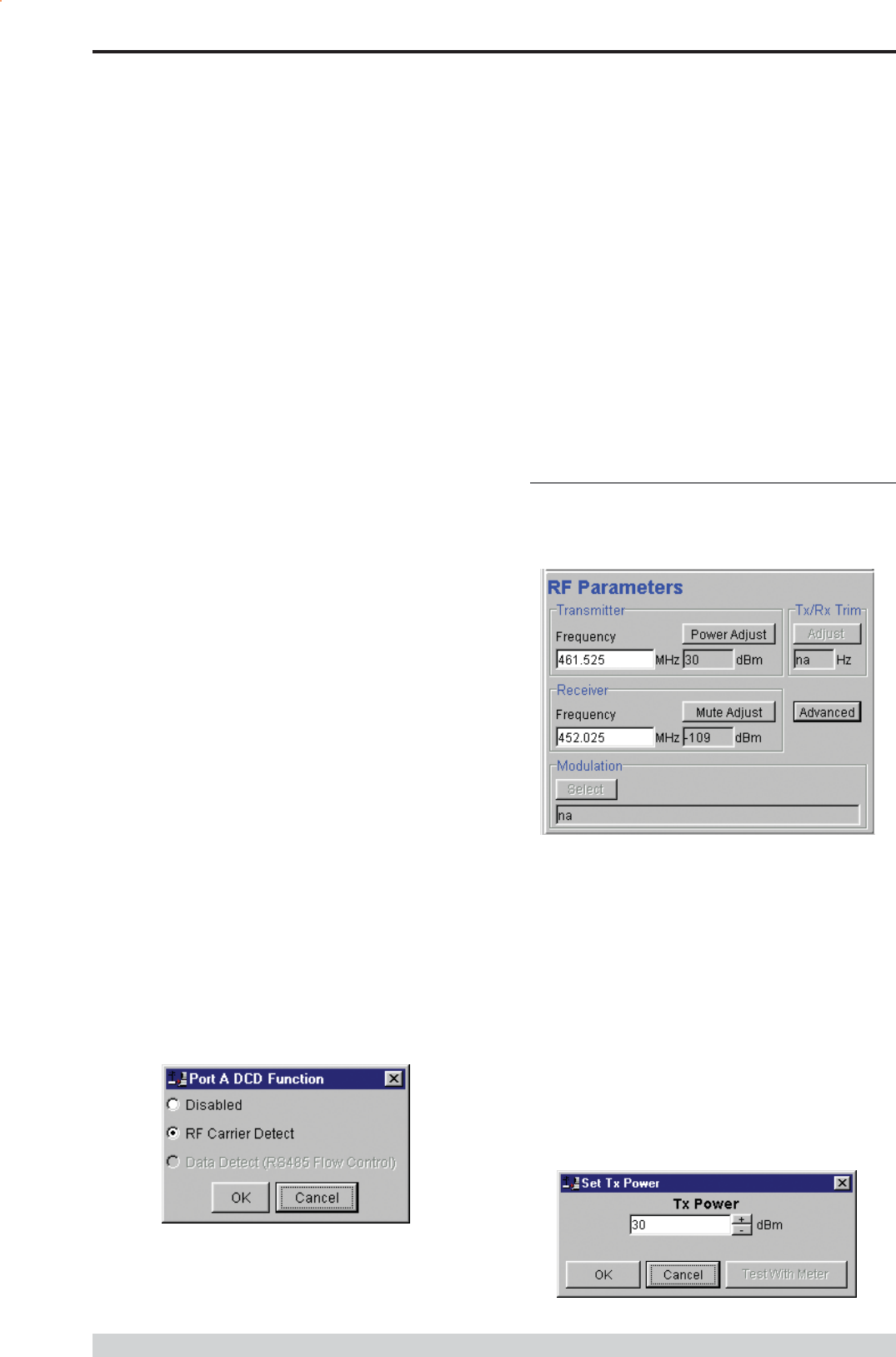
RF Parameters
This section of the main window permits adjustment of transmitter and
receiver, radio channel modulation scheme, frequency trim and
advanced features.
Transmitter
The transmitter can be configured for transmit frequency and power
level.
Frequency
The required transmit frequency in MHz can be entered in the display
field. The programmer checks that the selected frequency is in the
range for the particular model of radio and provides warnings if not.
Power Adjust
The currently selected transmit power is displayed below the button in
dBm. The power level can be adjusted by selecting this button which
displays a dialogue box. The up/down keys, or a typed in value, can
be used to select the required power level in dBm steps. There are
two methods for setting the power.
Part I TVIEW+ Management Suite - Programmer
DSR
DSR is permanently set to TRUE.
CTS
The CTS is a signal from the modem to the host informing the
host that the modem is able to accept incoming data on the TXD
line. It responds to the actions of the RTS line similar to the
operation of a standard line modem.
The CTS is FALSE if the RTS line is FALSE. Once the RTS line
is set to TRUE (signalling that the host wants to send some data
to the modem on the TXD line), then the CTS will be set TRUE
within 1ms, if the modem is capable of accepting more data.
The CTS line will be set to FALSE if the transmit buffer in the
modem exceeds 4075 bytes, or the number of queued frames
exceeds 29 to ensure that no overflow condition can occur.
RTS
The RTS line is used for two reasons. The first is to assert the
CTS line in response to RTS. The RTS line can also be used to
key up the transmitter stage of the modem.
DTR
The DTR line is used for flow control of data being sent from the
modem to the host controller. When the host is able to accept
data it sets this line to TRUE, and if data is available within the
modem, it will be sent to the host. If the host cannot accept any
more data, then it sets the DTR to FALSE, and the modem will
stop all transmissions to the host.
Xon/Xoff
If the flow control mechanism is XON/XOFF then the modem
uses the standard ASCII control codes of DC1
{^Q=11(Hex)=17(Dec)} for XON and DC3
{^S=13(Hex)=19(Dec)} for XOFF. The DTR input line is totally
ignored.
Note: There is no substitution mechanism employed in the
XON/XOFF protocol, so care must be taken when transferring
binary data to ensure that invalid flow control characters are not
generated.
Advanced
This button provides access to the advanced features of the port
configuration. When selected a dialogue box appears which permits
selection of the source for the port DCD output signal.
Page 49
E Series Data Radio User Manual
© Copyright 2004 Trio DataCom Pty. Ltd.
Using Factory Calibration
To use the factory calibration of the radio the desired power is set
immediately using the OK button in the dialogue box. This
method permits the transmit power to be set without energising
the transmitter. Note that although the transmit power has been
adjusted it must be written to NVRAM using the modem Write
function to ensure it is retained after a power on reset.
Using a Power Meter
To overcome manufacturing variations in the power setting a
more accurate setting of power can be achieved by the selecting
the Test With Meter button in the dialogue box. This displays
another dialogue box warning the user that the transmitter is about
to be energised and that the power meter used should be able to
handle at least 10 Watts from the modem.
Selecting OK in this warning dialogue box will energise the
transmitter which will also be indicated by the red transmit LED
on the unit. The power is adjusted using the up/down keys until
the required power level is obtained. Selecting OK will retain the
power setting and turn the transmitter off.
Note: Although the transmit power has been adjusted it must be
written to NVRAM using the modem Write function to ensure it
is retained after the modem is rebooted.
Selecting stop test will stop and leave you in power adjust
box. Cancel will stop test and take you back to the main
window.
Receiver
The receiver can be configured for receive frequency and mute level.
Frequency
The required receive frequency in MHz can be entered in the display
field. The programmer checks that the selected frequency is in the
range for the particular model of radio and provides warnings if not.
Mute Adjust
The currently selected mute level is displayed in the main window
below the button in dBm. The mute level can be adjusted by selecting
this button which displays a dialogue box. The up/down keys, or a
typed in value, can be used to select the required mute level in dBm
steps. Whilst a session is in progress with a unit the mute level
adjustment is live. Selecting OK will retain the mute level setting. Note
that although the mute level has been adjusted it must be written to
NVRAM using the modem Write function to ensure it is retained after
the modem is rebooted.
Whilst the modem is capable of receiving extremely weak radio
signals, and successfully extracting the data content from the
waveforms the mute level should be set to assist the modem in
filtering out unwanted signals. Unwanted signals can be the result of
background noise or interference. The mute level should be set at a
level above these unwanted signals and at a level low enough to
detect the wanted signal. Detection of a received signal above the
mute level is indicated by the RxSig LED on the unit.
Setting of a correct mute level at a base station is critical if collision
avoidance is operational in a point to multipoint system. In this situation
detection of noise instead of a valid transmission from the remote
modems will effectively lock out all of the remote units from
accessing and using the channel.
Due to normal manufacturing variations the actual mute level may
vary by several dBm to that selected. If a more accurate adjustment
is required an unmodulated signal of the correct frequency and desired
threshold level can be applied to the radio modems antenna connector.
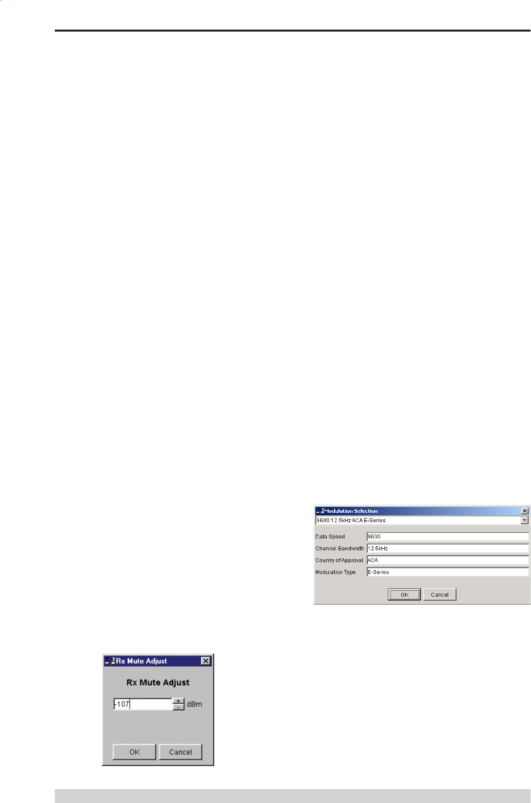
Modulation
The radio modem utilises a DSP to control the modulation of transmit
signals and de-modulation of received signals. This provides greater
flexibility in the ability of the radio modem to support new modulation
schemes whilst maintaining compatibility with existing modulation
schemes.
The currently selected modulation scheme is displayed in the main
window below the select button. The modulation scheme can be
adjusted by selecting this button which displays a dialogue box. The
desired modulation scheme can then be selected from the pull-down
menu in the dialogue box and retained using the OK button.
In the case of 12.5kHz channel radio modems the presently supported
modulation schemes include:
9600 12.5kHz ACA E Series. This is a new 9600bps
modulation scheme available in E Series products which
supports a significantly reduced delay between detection of a
valid RF carrier signal and demodulation of user data.
4800 12.5kHz ACA D Series. This is a current 4800bps
modulation scheme used in the D Series products to provide
backward compatibility.
Part I TVIEW+ Management Suite - Programmer

Page 50
E Series Data Radio User Manual
© Copyright 2004 Trio DataCom Pty. Ltd.
Tx/Rx (Frequency) Trim
The currently selected frequency trim, which is common to both
transmitter and receiver, is displayed in the main window below the
button in Hz. The frequency trim can be adjusted live by selecting this
button which displays a dialogue box. The up/down keys can be used
to select the required frequency offset in steps pre-determined by the
radio modem. Selecting OK will retain the frequency trim setting. Note
that although the frequency trim has been adjusted it must be written to
NVRAM using the modem Write function to ensure it is retained after
the modem is rebooted.
This facility permits correction for drifts in the frequency reference
caused by component ageing. For example, a standard crystal may
vary in fundamental frequency operation over 1 year by one part per
million. An adjustment range of ± 10ppm, displayed in Hz, has been
allowed for and if this is insufficient the unit should be returned to the
dealer/factory for re-calibration.
Advanced
This button permits setting of advanced features. When selected a
dialogue box appears which permits configuration of the type of
received data clock alignment method.
In the case of full duplex units the receiver is always active and is not
interrupted by transmissions from the unit as would be the case for half
duplex units. In this situation it is not necessary, or desirable in the
case of a base station, for the recovered data clock alignment to be
remembered between bursts of received signals. In this situation the
Receiver Full Duplex check box to the left should be selected.
Note: For half duplex units the Receiver Full Duplex check box
should not be set.
System Parameters
This section of the main window configures the PTT control, collision
avoidance, stream setup for routing of data, advanced features and
provides unit information.
PTT (Press To Talk) Control
RF transmission can be configured to occur permanently,
automatically on data received at Port A or Port B, or RTS being
asserted on Port A or Port B. A PTT timeout facility can be configured
to limit the period for which the transmitter is enabled. Each option is
selected by setting the control to the left of the description on the main
window. When PTT is active the Tx LED on the unit is illuminated
and RF power is being fed to the antenna.
Permanent Tx
This will cause the transmitter to be permanently enabled (keyed) and
displays another dialogue box warning the user that the transmitter will
be energised immediately after the configuration is written to the unit.
Selecting OK confirms this setting. The other PTT selections are
disabled when this option is selected.
Note: This option is only available for half duplex units when being
programmed locally.
Auto On Data
This will cause the transmitter to be enabled (keyed) automatically on
data received at Port A or Port B and included in a complete frame for
transmission over the radio channel. The maximum period for which
the transmitter will be enabled is limited by the PTT timeout setting.
From Port A RTS
This will cause the transmitter to be enabled (keyed) on Port A RTS
being asserted. The maximum period for which the transmitter will be
enabled is limited by the PTT timeout setting. Applications which rely
on establishing a link ahead of data being transferred require this
method of activation.
From Port B RTS
This will cause the transmitter to be enabled (keyed) on Port B RTS
being asserted. The maximum period for which the transmitter will be
enabled is limited by the PTT timeout setting. Applications which rely
on establishing a link ahead of data being transferred require this
method of activation.
In the case of 25kHz channel radio modems the presently supported
modulation schemes include:
19200 25kHz ACA E Series. This is a new 19200bps
modulation scheme available in E-Series products which
supports a significantly reduced delay between detection of a
valid RF carrier signal and demodulation of user data.
9600 25kHz ACA D Series. This is a current 9600bps
modulation scheme used in the D Series products to provide
backward compatibility.
Part I TVIEW+ Management Suite - Programmer
Page 51
E Series Data Radio User Manual
© Copyright 2004 Trio DataCom Pty. Ltd.
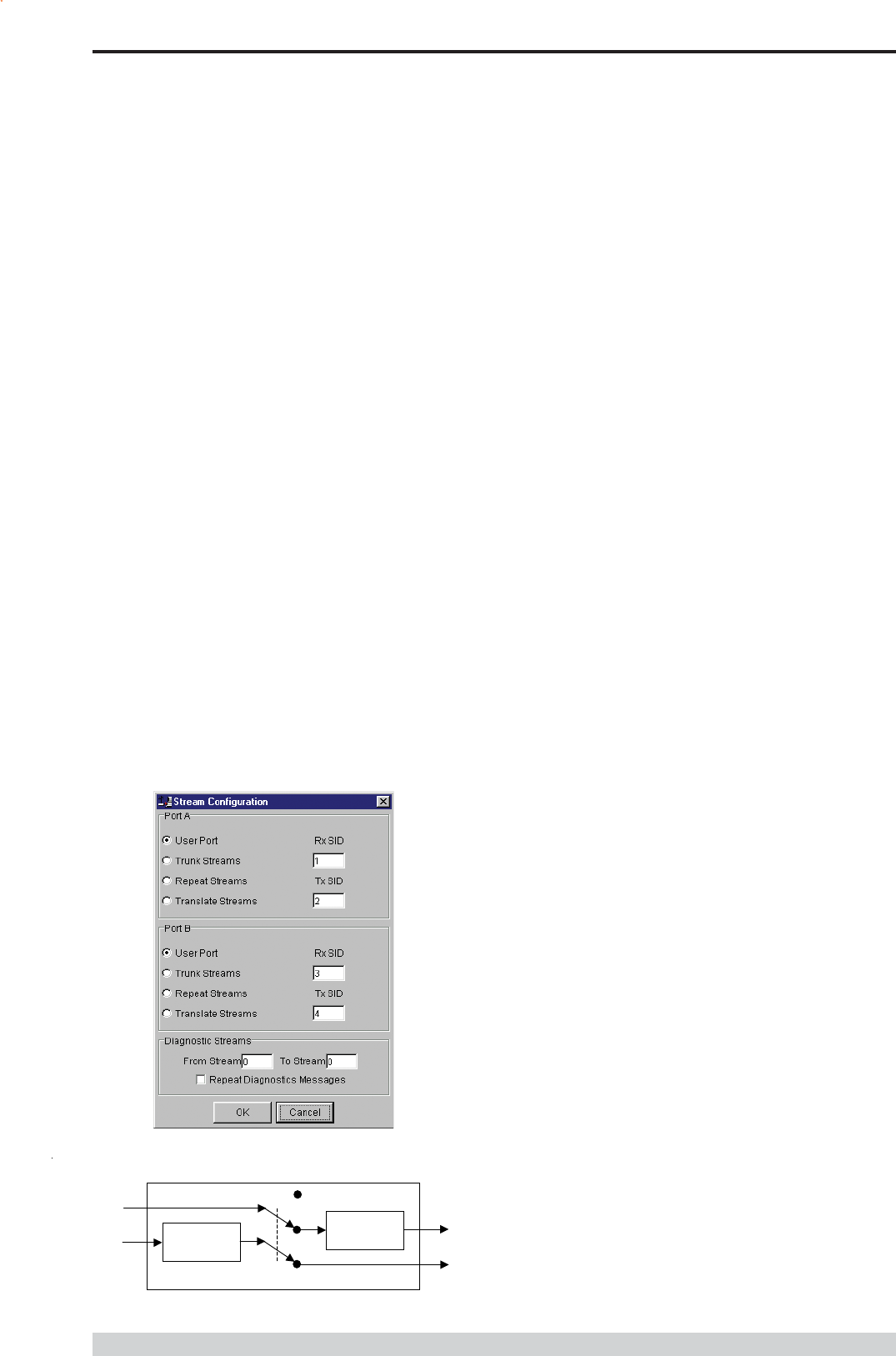
Stream Setup
This button brings up a dialogue box to permit editing of Stream
IDentifier (SID) codes which are used by the modem as the
addressing mechanism for data stream routing. A SID code can be
placed at the start of each data frame as it is sent over the radio
channel. The receiving modems use this code to determine how to
route the data message. The modem supports simultaneous operation
of both Port A and Port B over the one radio link, along with the
inclusion of a diagnostics data stream.
Each port is independent and fully supports one of four options which
can be chosen as described below. Note that the port B parameters
are greyed out when port B is not enabled.
The following diagram illustrates the structure of the stream routing
function for each data port.
SID
Filter
SID Adder/
Translator
Port Data In
Rx Data In Tx Data Out
Port Data Out
Stream Router
User,Trunk
Repeat,Translate
User Port
This option is selected by clicking on the User Port button and filling in
the RXSID and TXSID fields to the right.
In the User Port mode (Referred to in the previous programmer as
MUX/DEMUX mode) all SID code operations are performed
transparently to the user. Data placed into a user port which has been
assigned a specified SID code, will only be received by a modem at
the other end of the radio link that has a user port assigned with the
same SID code.
In this way, Port A and Port B can be assigned different SID
codes, thereby separating the data streams.
Two SID codes values are available for each user port RXSID and
TXSID. The RXSID codes apply to the data being received by the
modem, and the TXSID codes apply to the data being transmitted by
the modem. This allows for different transmit and receive codes if
required, but generally they would be both the same.
A situation where Tx and Rx SID codes may be different is in a
repeater configuration. In this type of application all data messages
sent to the repeater will be repeated. Thus by having different Tx
and Rx codes, a control unit will not hear its own transmission, and
remotes will not hear the reply from any other remote.
If the diagnostics facility is installed in the modem, then it too has a pair
SID codes. The diagnostics data simply uses a different data stream
or streams to the user data, but is processed internally by the modem.
If access to the diagnostics facility is required, similar to when the
diagnostics utility is used with the modem, then the data port
concerned and the diagnostics stream, must have the same SID
codes assigned to them. Alternatively the System port can be used,
which is 19.2K, Slip.
(Previously TXSID was referred to as SIDA2 or SIDB2 and RXSID
was referred to as SIDA1 or SIDB1 for ports A and B respectively).
Trunk Streams
In the Trunk Streams mode, data that is inputted into the modem for
transmission must have a SID code appended to the start of the data
packet by the user. The modem does not do it as in the User Port
mode of operation. When a data packet is received by the modem, it
is passed through a SID code filter which is bounded by a lower and
upper limit of SID codes. The SID code is not stripped off from the
user data.
For instance the lower bound is 03 and the upper bound is 07. If a
message is received with a SID code of 02 appended it would not be
passed to the user. If a message is received with a SID code of 04
then it is passed to the user, with 04 at the start of the frame.
The SID codes can range from 0 to 255, and physically consist of the
byte value of the code i.e. a code of 156 is equivalent to 10011100
binary.
PTT Timeout
The PTT timeout facility is used to disable the transmitter if it exceeds
the designated time. The timeout value can range from 1 to 255
seconds and the facility is disabled by setting a zero value.
The timeout value chosen for this should be set according to system
requirements which may include:
Prevention of a remote unit remaining keyed up and locking out
all other remote units in a point to multipoint system.
Limiting the period a remote unit remains keyed up to prevent
battery drain in a low power application.
Note: If a PTT timeout occurs before completion of a data
transmission data will be lost.
Part I TVIEW+ Management Suite - Programmer
Page 52
E Series Data Radio User Manual
© Copyright 2004 Trio DataCom Pty. Ltd.
To select the Trunk Streams option click on the Trunk Streams button
of the port to be used and fill in the fields to the right. The From field
is for the lower SID code limit and the To field for the upper SID code
limit.
Note: When using Trunk Streams an unambiguous packet delineation
scheme (e.g.. SLIP) should be used so that the SID code in the user
data can be decoded correctly.
Repeat Streams
The modem is capable of operating in a repeater mode. Each user
port can be configured as a separate repeater. The associated user
ports are effectively disconnected from the outside world when in
repeater mode. Data received from the radio channel is passed
directly to the transmitter, and placed back onto the radio channel.
The repeater must receive a complete frame of data before it is
retransmitted. In some systems this store and forward delay may be
significant, and careful selection of maximum frame sizes configured at
the source unit must be considered to minimise the delay.
To enable the mode for the port click the Repeat Streams button and
select the range of SID codes on frames to be repeated.
Translate Streams
This is essentially a hybrid of the User Port and Repeat Streams
functions available on a port. Whereas the latter repeats a range of
streams, this function instead translates one stream to another, by
demultiplexing one stream (defined by Rx SID), and re-transmitting it
with a new stream address (defined by Tx SID).
Note: Data is not presented to the user ports.
Diagnostics Processor
The Diagnostics Processor uses several streams defined by the range
of SID codes. The diagnostics commands received on each stream
are sent back over the same stream. The Diagnostics Processor is an
option which must be enabled before this section of the menu will
become active.
Diagnostics Repeat
This option can be toggled on and off simply by clicking the
button.
Some applications will require that the master unit in a point to
multipoint system to repeat diagnostics frames only (i.e. the
master modem is not set up as a repeater).
This will be the case when the system diagnostics controller is
connected to a remote unit in the system, and it polls the system
population from this point. The master unit must retransmit any
diagnostic frames that are not addressed to itself onto the
remainder of the population.
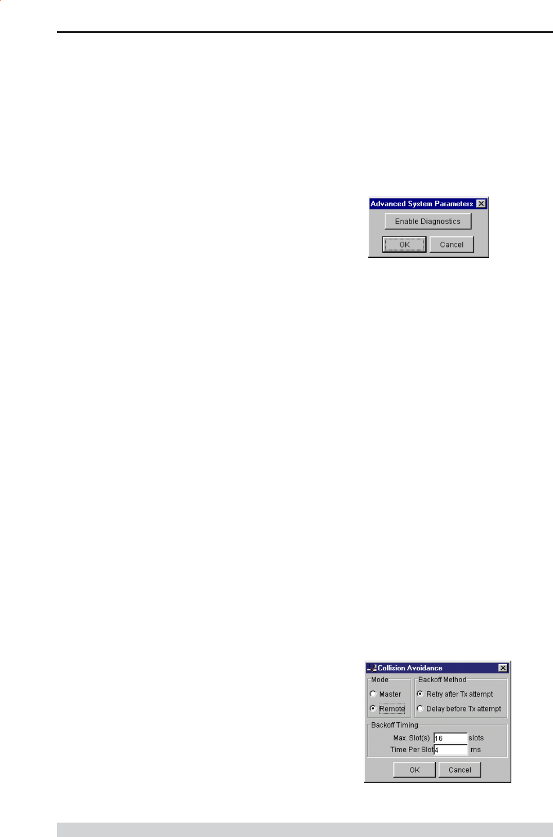
Advanced
This button permits setting of advanced system parameter features.
This presently includes enabling the diagnostics facility within the unit.
Once enabled the diagnostics utility can be used to monitor the
performance of the unit.
The Enable Diagnostics button should be selected and the 8 character
diagnostics key code entered prior to selecting OK. If the key code is
accepted or has been previously entered the Enable Diagnostics
button will be greyed out. Contact your supplier for Key Code
purchase.
Collision Avoidance
In a point to multipoint system the master unit (usually a base station)
can transmit at any time and the remotes will all receive the broadcast
signal. However, if more than one remote unit transmits at a time,
then a collision will occur during the multiple transmissions, resulting in
a loss of data from one or more units.
Two collision avoidance mechanisms have been included in the
modem. The standard (Digital) method utilises a signalling channel
which is embedded in overhead data transmitted over the radio
channel. The second method utilises detection of a carrier signal to
postpone transmission of data. Both methods require configuration of
several options for successful operation.
The desired option for collision avoidance is selected by checking the
control button to the left of the description on the main window.
None
When selected this turns off all collision avoidance mechanisms. This
should only be used in point to point applications.
Digital
This is the standard method of collision avoidance and utilises a
channel busy indication bit in the signalling channel transmitted to all
remotes for control. When selected a dialogue box appears and
several options must be configured:
Part I TVIEW+ Management Suite - Programmer
Page 53
E Series Data Radio User Manual
© Copyright 2004 Trio DataCom Pty. Ltd.
Mode Master or Remote. When the master unit receives
a valid transmission from a remote unit it sets the channel busy
indication bit. This busy bit is interpreted by the other remotes to
not transmit. Once the transmission from the first remote ends
the master unit resets the busy bit to indicate the channel is
now clear to transmit on. The master unit, which is normally a
base station, takes about 5ms to detect a transmission from a
remote unit and set the channel busy indication bit on the radio
channel. During this period collision of remote transmissions
can still occur and is unavoidable.
Note: The master can only be a full duplex unit.
Backoff Method Retry after Tx Attempt or Delay before Tx
Attempt. The method chosen is system dependent and can
only be configured if the mode is remote. The former is best
used when data responses from remotes are largely
asynchronous. The latter is best used when this is not the
case.
Backoff Timing Maximum Slots, Time per Slot. This can
only be configured if the mode is remote. When a remote is
ready to transmit data but it finds the busy bit from the master
set it holds back its transmission for a random backoff time
after which it tries to transmit data again. This ensures that
modems waiting to be allowed to transmit do not re-attempt to
do so at the same time. The Maximum Slots (1 to 16) and
the Time per Slot (1 to 255ms) are used to calculate the
backoff time by multiplying the slot time by a random number
between 1 and the maximum slot number. For example if the
time per slot is 30ms and the maximum slots is 4, the random
backoff times can be 30, 60, 90 or 120ms.
As the channel busy indication bit is critical for reliable operation default
interpretation of this bit is defined in the remote units. If the master
modem stops transmission (or has not yet started) the remote will
interpret that the channel is busy and will not transmit until the master
comes on line.
Carrier Detect
This method of collision avoidance utilises a carrier transmitted to all
remotes to indicate that the radio channel is busy. When selected a
dialogue box appears and several options must be configured:
Mode Master or Remote. When the master unit receives
a valid transmission from a remote unit it transmits a carrier
signal to indicate busy. Of course the master will also initiate a
transmission if it has data to send. The transmitted carrier is
interpreted by the other remotes to not transmit. Once the
transmission from the first remote ends the master unit stops
transmission to indicate the channel is now clear to transmit on.
The master unit, which is normally a base station, takes about
5ms to detect a transmission from a remote unit and transmit a
carrier signal. During this period collision of remote
transmissions can still occur and is unavoidable.
Note: The master can only be a full duplex unit and cannot be
permanently transmitting. For half duplex and simplex systems
all units should be set as Remote (no Master).
Backoff Timing Maximum Slots, Time per Slot. This can
only be configured if the mode is remote. When a remote is
ready to transmit data but it detects a carrier signal from the
master set it holds back its transmission for a random backoff
time after which it tries to transmit data again. This ensures that
modems waiting to be allowed to transmit do not re-attempt to
do so at the same time. The Maximum Slots (1 to 16) and
the Time per Slot (1 to 255ms) are used to calculate the
backoff time by multiplying the slot time by a random number
between 1 and the maximum slot number. For example if the
time per slot is 30ms and the maximum slots is 4, the random
backoff times can be 30, 60, 90 or 120ms.
Unit Information
Part I TVIEW+ Management Suite - Programmer
The information displayed is intended to assist the user to identify the
radio modem as well as support should their services be needed.
Radio Model refers to the type of unit. The ER450 is a remote
unit and the EE450 is a exciter inside a base station unit.
Radio Type refers to the frequency band supported by the radio
as well as the channel bandwidth. For example 51A02 is a type
51 band with a 25kHz channel.
Page 54
E Series Data Radio User Manual
© Copyright 2004 Trio DataCom Pty. Ltd.
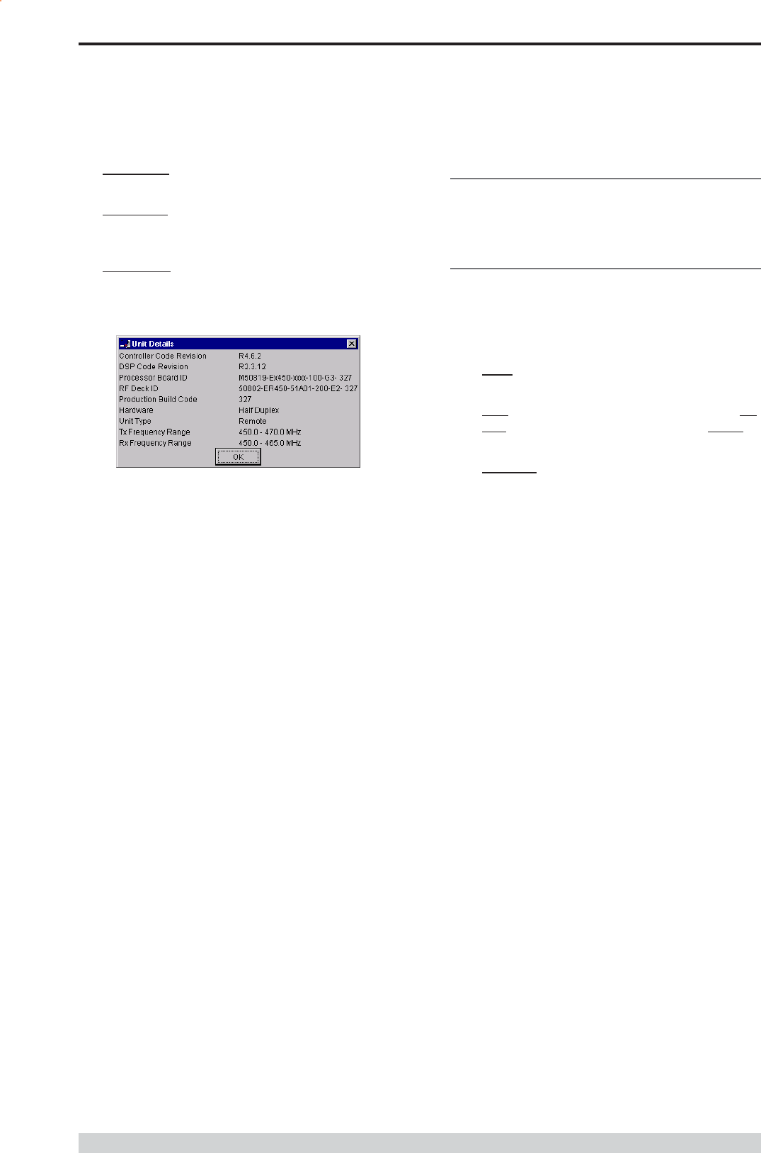
Unit Information - Details
More detailed information is also available to assist in identifying
components installed in the unit (remote, base station or hot standby).
The additional information provided is:
Controller Rev refers to the microcontroller firmware component
version for the radio.
DSP Code Rev refers to the DSP firmware component
version for the radio.
Processor Board ID refers to the processor board identification
number and hardware revision information for the radio.
RF Deck ID refers to the RF deck board identification number
and hardware revision information inside the radio.
Production Build Code refers to the automated production test
and calibration sequence used during manufacture of the radio.
Hardware indicates whether the radio is half or full duplex.
Unit Type indicates whether the unit is recognised as a remote
or base station.
Tx and RX Frequency Range indicates the frequency range
for which the radio is capable of being operated in.
In the case of a base station unit the following additional information is
provided:
Base Firmware Pack refers to the firmware package version
installed in the base station (front panel) controller which is
separate to the radio installed. There are several components
associated with this firmware package and a single version
number is used to identify them.
Base Controller Rev refers to the microcontroller firmware
component version for the base station.
Messages
The message window provides a log of error messages occurring
during use of the programmer utility. Several error messages may
occur as a result of a selection.
Status Bar
The status bar is located at the bottom of the main window and
provides information regarding communication actions occurring with
the radio data modem.
Additional fields located on the status bar include:
Unit ID refers to the identification label used by the diagnostics
utility. This is currently the same as the units serial number.
Mode refers to the type of session established. It can be a File,
Local indicating a local port connection to the unit or Remote
indicating communications is via a radio channel.
Rotating bar progress indicator showing data is being
transferred to or received from a unit.
Part I TVIEW+ Management Suite - Programmer
Diags Installed is set to yes or no depending on whether the
diagnostics key has been set in the unit.
Serial Number is unique to each unit and is set within the unit at
time of production as well as included on the label fixed to the
unit.
Firmware Pack refers to the firmware package version installed
in the radio. There are several components associated with
microcontroller and DSP firmware installed and a single version
number is used to identify them.

Page 55
E Series Data Radio User Manual
© Copyright 2004 Trio DataCom Pty. Ltd.
Part J TVIEW+ Management Suite - Remote Diagnostics & Network Controller
Introduction
This section covers the operation of the Remote Diagnostic and
Network Management Controller Software Version 3.7.X or greater.
Overview
The Diagnostic Controller is a Windows© based program, that can be
run on a standard desktop or laptop PC.
The software runs in the 32 bit Windows environment and offers many
options and configurations which are easily accessible via pop-up
windows. These include group or timed polling, remote switching of
duplicated base stations, viewing of databases, logging and trending of
real time parameters , etc.
The Diagnostic Controller can be installed to run as a stand-alone
package, or as part of the TView+ Management Suite.
It is for use in conjunction with the D & E Series of data radio modems
and can be used for simple point-to-point links, or for more complex
point-to-multipoint and multilayer link systems.
The diagnostic facilities allow retrieval of packet statistics from each
radio modem. These statistics are used to calculate Packet and Bit
Error Rates, a units condition/health, network efficiency and
bandwidth utilisation.
The use of the diagnostics facilities provided by the controller gives the
radio modem system designer and operator a powerful tool for both the
maintenance and continuing reliability of their system.
The general operating parameters that can be obtained from remote
modem units are:-
Last RSSI level.
Last transmitted power level.
Receive frequency offset.
Power supply voltage level.
Current internal temperature.
These are displayed on the controllers screen in a quick read format
of bar graphs, as well as detailed response listings.
For the E Series radio modems to respond to the diagnostics
controller, they must have this option configured, either at factory build,
or at a later stage, by the programmer. Contact your supplier for further
details.
Diags installation can be verified with the TVIEW+ Programmer. If
Diags is installed, it will be stated in the unit information dialog box.
The diagnostics data stream operates alongside the main user data
stream. No interference between the two streams occurs, so as far
as the primary user of the data system is concerned, the diagnostics
data does not exist.
Features
32 Bit Windows Based User Software.
Full graphical presentation.
Full SCADA style features such as database, trending,
networking, etc.
Able to interrogate and display important operating parameters
of each radio modem.
Provides performance data of any unit - good frames received,
bad frames received, packet error rate, transmitted packet
sizes, channel usage, etc.
Provides statistical Packet Error Rate (PER) performance
calculations for any unit.
Provides powerful network tools such as channel occupancy
statistics, average received transmission duration, etc.
Can be set to background poll radio system for continuous
system monitoring and logging.
Provides full time/date stamped Status and Alarm logging/
reporting. A relational database is created and managed using
Microsoft Jet database engine Ver3.5. The database file, which
is an .mdb file, can be accessed with external programs
such as Microsoft Access.
System Description
General
The diagnostics process is based on a series of polls being transmitted
to the remote modem units with each modem having its own unique
assigned address which is factory preset.
When a diagnostic poll is received by a modem it checks to see if it is
addressed to itself, and if so, it responds with its diagnostic data back
to the controller. If it is not addressed to the modem, the modem
simply passes the message on, and does not respond to the
controller.
In a multilayer system, several pass ons may occur before the
destination modem is reached.
The modems diagnostic response message is addressed to the
controller, and as each modem in the chain decodes this message it
will pass it back, eventually the message reaches the controller for
processing.
The controller software provides a database to hold the modem units
associated data (i.e. Serial number, assigned name, location, alarm
limits, SID code address, base station pairing information, status poll
response data, alarms, etc).
The units address is the serial number of the unit which is factory
preset. The name is any mnemonic that the user wishes to attach to
the modem. This name is then used to address the unit for access to
diagnostic facilities.
Part J TVIEW+ Management Suite -
Remote Diagnostics & Network Controller

Page 56
E Series Data Radio User Manual
© Copyright 2004 Trio DataCom Pty. Ltd.
The responses from the modem have boundary limits placed on them.
If a response is outside these limits then an alarm is raised. For
instance, the DC supply volts can have a lower limit of 12V, and an
upper limit of 16V. Should a response to a poll received show that the
DC volts is at 11V, then an alarm is reported.
A unit can be excluded from a poll sequence by removing it from the
poll group.
Intensive polling of a single unit is possible using the Individual polling
facility.
A poll run can be set up. A time can be designated for the controller
to poll each of the modems in the system. This may be useful for
systems that have a low traffic period where diagnostics can be
slotted in, thereby spreading the data throughput of the system more
efficiently.
The screen is divided into three main scrolling sections - Status Polls,
Alarms and Base Station Activities. The status poll section displays
current poll activity while the alarm section displays any polls alarms
which have been reported. The Base Station activity section displays
any changeovers that have occurred to Hot Standby Base Units - if
no Hot Standby Base Stations are employed within the system, this
section will remain blank.
A relational database is created and managed using Microsoft Jet
database engine Ver3.5. The database file, which is an .mdb file,
can be accessed with external programs such as Microsoft Access.
All polls and alarms are time and date stamped and saved to the
database. All database entries can be sorted and printed.
For some multilayer systems, Stream Identifier (SID) Codes may
have to be added to the diagnostic data packets. Each modem can be
assigned a SID address (the default is 00) and the SID code feature
enabled.
Refer to Appendix A Technical Notes for further details of SID code
addressing.
The diagnostic core of each radio (Firmware Version 2.4.0 and above)
stores packet statistics for later retrieval. The Diagnostic controller
software uses these statistics to calculate packet and bit error rates,
network efficiency, bandwidth utilisation, and radio link integrity. These
network analysis features are an invaluable tool for larger networks.
In the transmit direction, each radio modem can report the number of:-
data bytes transmitted (TxByteCnt).
frames transmitted (TxFrameCnt).
With these counters one can then calculate average frame size,
average frame rate and channel utilisation.
In the receive direction, each radio modem can report the:-
Data bytes received (GoodByteCnt).
Good frames received (GoodFrameCnt).
Bad frames received (BadFramCnt).
Total time the radio has received signal (RSSIgoodTicker).
Lost synchronization count (LostSynchCnt).
Lost RSSI count (LostRSSICnt).
These counters can be used to calculate average frame size, average
frame rate, channel occupancy, channel utilisation and link integrity.
Radio modems with Firmware Revisions 2.4.x and above have the
advanced statistical counters as noted above. Firmware revisions
below this (i.e. 2.3.x) only have Good Frame count, Bad Frame
count, Lost RSSI count and Lost Synch Count available. The
diagnostic controller will detect which firmware the radio has, and only
report the available counters.
All these features combine to provide a powerful tool for the system
operator.
Modem Connection
The diagnostics controller normally connects via a COM port on the
controller PC and the System Port on the radio modem (Port A &
B can be used if required).
Note: The controller can connect to any port of any data radio modem
within the system as long as the data radio port is configured
accordingly. When Settings is selected, the controller will interrogate
the computers coms ports and display the available ports. Possible
valid com ports are 1-16 or None. Choose the desired port. None
allows you to free the com port for use with other programs without
exiting the diagnostic.
The modem port must have its SID codes enabled, and have the SID
code set to the system diags SID (normally this is set to 00).
The data format used is the SLIP protocol, running at 9600 baud, No
parity, 8 data bits and 1 stop bit. Appendix B SLIP Protocol
contains a detailed definition of the SLIP Protocol.
COM1 of the controller PC is to be directly connected to the 9 way D-
Min of the modem using a 3 wire interface (see drawing below).
Should the PC have a 25 way connector, then the standard RS232,
25 way to 9 way conversion should be used.
Part J TVIEW+ Management Suite - Remote Diagnostics & Network Controller
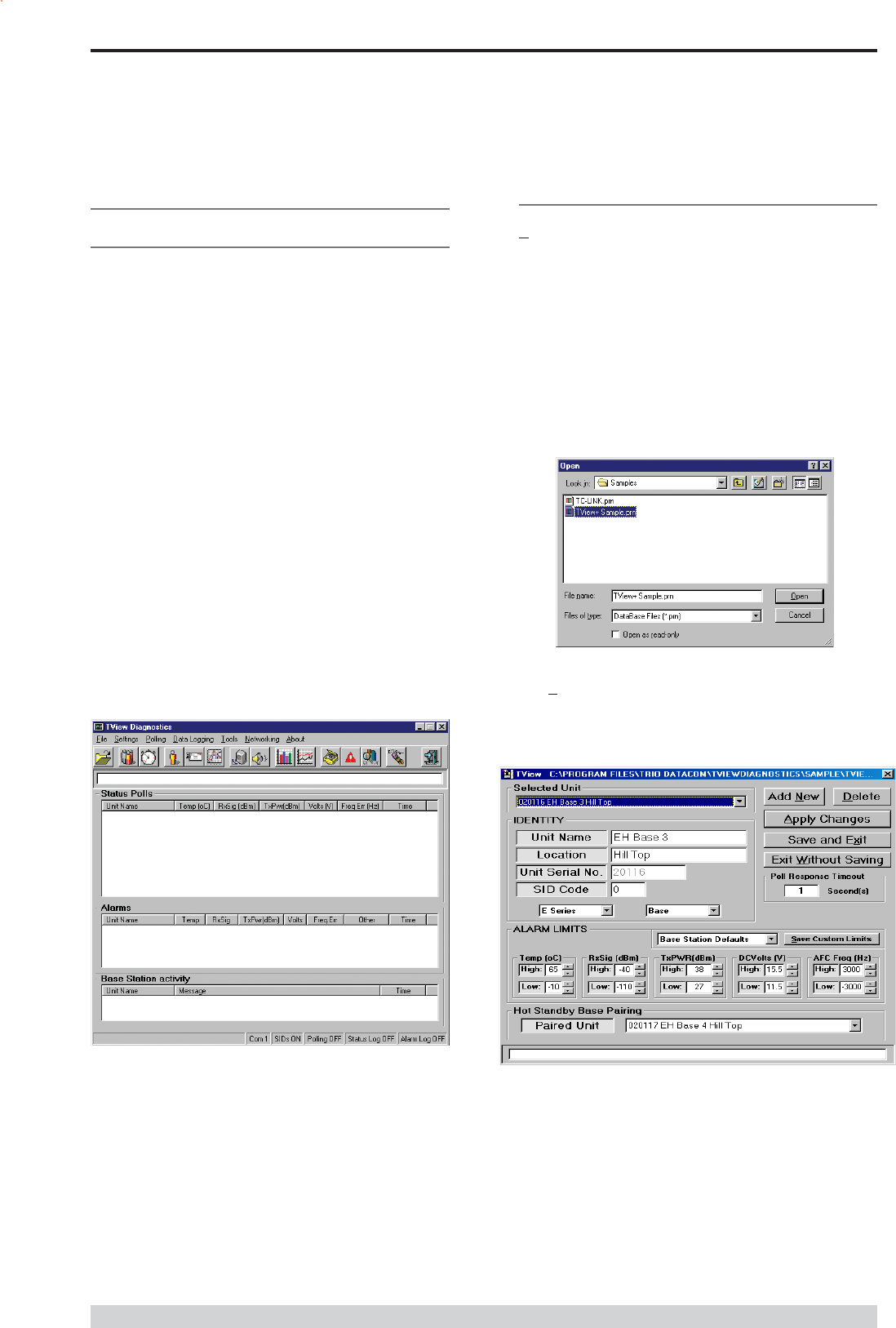
Page 57
E Series Data Radio User Manual
© Copyright 2004 Trio DataCom Pty. Ltd.
Operating Instructions
General
When the Diagnostic controller starts, a presentation screen is
displayed which will then lead you into the main diagnostics screen.
This is where all the major functions of the controller are accessed.
The main screen presents the operator with the typical Windows pull
down type menu bars - File, Settings, etc. Icons of the most
commonly used selections are also provided across the top of the
screen.
This screen is divided into 3 main sections:-
1. Status Polls screen which displays all poll results
obtained.
2. Alarms screen which displays any alarms that occur.
3. Base Station Activity screen which displays any
changeovers that occur with Hot Standby Base Stations within the
system.
The line above Status Polls is a Processing Status Bar. It will
display messages about errors, warnings and poll processing.
The bottom row of the screen also displays a summary of the
configured parameters such as which COM port is being used,
whether SID codes are on or off, whether polling is enabled or
disabled, current database path and file name, etc.
Menu Selection
File Menu
To utilise the Remote Diagnostics facilities, a database must be created
which includes the individual serial numbers, alarm parameters and
various other parameters of each unit.
Note: Not all options are available for some types of configurations.
Where these options occur, they are noted.
The file menu allows the operator to create a New database, Open an
existing database, Add/Edit/Delete a database or View an existing
database. All such database tools utilise standard Windows type
formats for file selections as shown.
File - Add/Edit/Delete
After creating a New database or Opening an existing database, the
Add/Edit/Delete menu can be accessed.
Selected Unit
Selected unit is a pull down selection box, for selecting a unit to view
or edit.
The bottom line is a Processing Status Bar. It will display
messages about errors, warnings and poll processing.
Part J TVIEW+ Management Suite - Remote Diagnostics & Network Controller

Page 58
E Series Data Radio User Manual
© Copyright 2004 Trio DataCom Pty. Ltd.
Unit Name and Location
Unit name is required and must be unique (max. 20 character).
Location allows the user to enter descriptions of sites and their
locations (optional, (max. 20 character).
Unit Serial Number
Is the factory preset unique serial number of the unit. This is obtained
from the label located on the unit or read from the unit using the
Programmer. On base stations the serial numbers must be read from
the lid label or electronically with the programmer.
SID Code (Diagnostic Stream Identifier)
Is the SID code address number being used by the unit for the
diagnostics stream. This is normally set to 0. Check the radio units
programmed configuration for confirmation and or system configuration.
Unit Series
Select D Series or E Series.
Select Base or Remote.
Poll Response Timeout
Is the time in seconds the Diagnostic controller will wait for a response
from the remote unit. When a time out occurs, the controller will retry.
If three poll attempts fail then the poll request is terminated, and a No
Acknowledge (No Ack) message will appear in the alarms window.
One second is usually more than enough wait time. In a multilayer
system, longer response times may be necessary.
Alarm Limits
Allows the user to set thresholds for each unit which, when exceeded,
will report an alarm. Default settings are provided for remote devices
and base stations. These are selected by clicking on the appropriate
buttons presented.
Defaults drop down box
Choose either Remote Modem Defaults or Base Modem Defaults
from the drop down list. Click Save to save customised default
values to the base or remote defaults for later recall.
This section of the main window permits adjustment of transmitter and
receiver, radio channel modulation scheme, frequency trim and
advanced features.
Hot Standby Base Pairing (HSC Only)
In a Hot Standby configuration two base stations are connected to one
Hot Standby controller. For proper diagnostics management both base
stations should be paired together. In a hot standby configuration, only
one base station can be online (ie: able to transmit) at any one time.
Diagnostics is still available from the off-line base stations (via the on-
line base station).
Note : This option is only available if more than one base is
configured in the database.
Add New Button
Click this button to add a new radio modem to the database. The
Selected Unit, Name, Location, Unit Serial numbers and Hot Standby
Base Pairing fields will be cleared, ready for the entry of a new unit.
After filling in the details click the Apply button to complete entry.
Apply Button
Applies changes to selected units or complete the add new radios to
the data base. Additions and changes made on the screen do not
result in changes to the database unless this button is activated. This
must be done before selecting a new serial number/unit. Note that the
newly changed database will not be saved to disk until the Save and
Exit button is activated.
Delete Button
Allows deletion of units from the database.
Note: Deleting a unit from the database will delete all its associated
status poll and alarm history.
Click and a selection list of serial numbers will appear. Select one at
a time and then press the Delete button on the selection box.
Save and Exit Button
Press this button to save the newly changed database and then exit.
Additions and changes to the database will be saved to disk as long
as the Apply button was pushed.
Exit without Saving Button
Press this button to exit without saving the newly changed database.
Part J TVIEW+ Management Suite - Remote Diagnostics & Network Controller
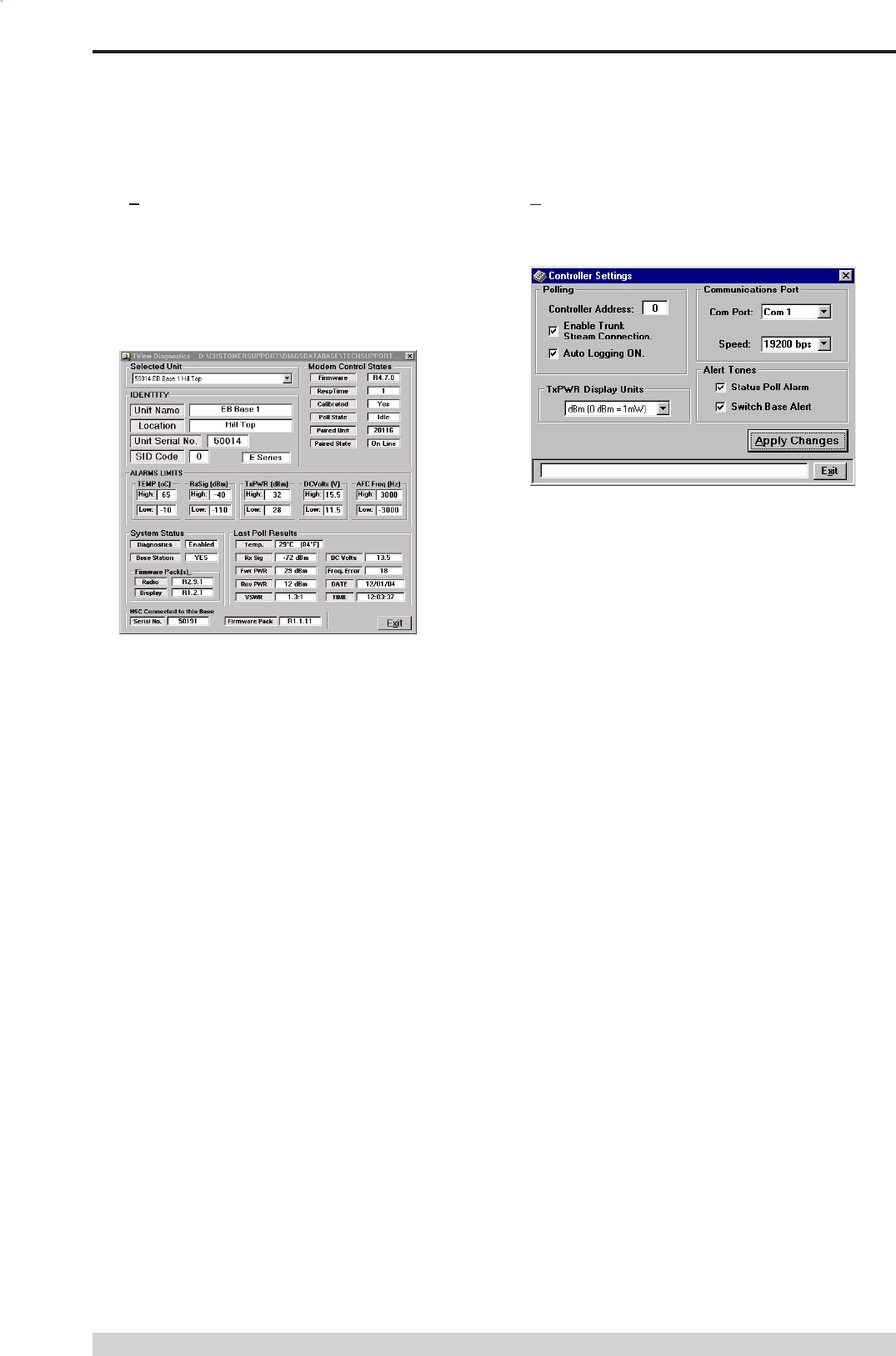
Page 59
E Series Data Radio User Manual
© Copyright 2004 Trio DataCom Pty. Ltd.
File - View (view only)
The View Screen shows the selected unit alarm limits and last poll
results (radio and firmware information). This page will also auto
refresh (every 6 seconds) if the unit selected for viewing is part of an
active single or group poll.
Note : The view window is different for Remote radios and Base
Stations (with and without a Hot Standby Controller-HSC).
Settings
The settings menu allows the user to configure various setup
parameters. These include:-
Communications Port
With the pull down box, select the required communications port.
Com 1 to Com 16. Select the required com port speed (9k6 or
19k2bps). Default is 19k2bps.
Controller Address
Normally set to 0. Networks which have multiple controllers active,
should use different controller addresses, so responses from remotes
are ignored if the poll was not sent by that controller.
Enable SID Codes
Enabled or disabled (Default enabled). In some systems, external
application of SID codes is used as a method of giving the modems in
the system specific data addresses. The modems are placed into the
stream routing mode, and the user (e.g. Diagnostic controller)
supplies the SID code at the start of each data packet to be
transmitted. In this way the user can steer the data flow through the
given network path.
Should the diagnostics controller be used in such a network then it too
needs to append the data addresses or SID codes to the beginning of
all data messages sent.
In the controllers database record for each modem, a field is supplied
where the user can select the SID code for that particular modem. By
selecting the Diagnostic SID code that suits the system topology, the
diagnostics data messages can be routed successfully to the correct
destination.
Auto Logging ON
When enabled all logging functions will be activated when polling is
turned on.
Alert Tones
When enabled will emit a tone from the PC speaker or sound card
when Status poll alarms occur and/or Base Station changeovers
occur.
Tx Power Display Units
Select either dBm or milli Watts as the display units. Power will
be displayed throughout the system in the selected power
measurement unit.
Note: Power will always be stored in the database file as milli-watts
Part J TVIEW+ Management Suite - Remote Diagnostics & Network Controller
Modem Control States :
Firmware : The current modem firmware version.
Calibrated : Indicates calibration status of diagnostics.
Paired Unit : Serial No of other base in a Hot Standby Configuration
(HSC Only)
Paired State: Indicates if paired base is currently the on-line or off-line
unit (HSC Only)
System Status :
Diagnostics : Enable or Disabled
Base Station : Indicates if unit is a Remote or Base Station
Firmware Packs : (Base and HSC Only)
Radio : Base Station Firmware Version
Display : Base Station Display controller firmware version
Last Poll Results :
Temp : Radio Temperature
Rx Sig : RX Signal Strength
Fwr PWR : Forward TX Power
Rev PWR : Reverse TX Power
VSWR : Voltage Standing Wave Ratio
- VSWR has white background when less than 2.0:1
- VSWR has yellow back ground when greater than 2.0:1 but
less than 3.0:1
- VSWR has red background when greater than 3.0:1
DC Volts : Supply Voltage
Freq Error : RX Freq Error
Date : Date of Last Poll
Time : Time of Last Poll
HSC Connected to this Base (HSC Only) :
Serial No : Serial No. of Hot Standby Controller
Firmware Pack : Firmware version of HSC

Page 60
E Series Data Radio User Manual
© Copyright 2004 Trio DataCom Pty. Ltd.
Polling
In order to obtain diagnostics information, the diagnostics controller
provides a number of automatic polling facilities, which include: Group
polling, Timed polling and Individual polling. The Group and Timed poll
facilities will automatically cycle through a selected group of units at a
predetermined interval (in seconds). The Individual poll facility permits
intensive polling of a single unit at a selectable rate, independent of any
Group polling that may be active at the time.
When the modem is polled for the first time, the controller will poll (ask)
the radio for its calibration constants and firmware revision (these can
be viewed in the View window under the File menu). When this
initialisation procedure is complete, status polling can commence. If
the radio were to perform a cold boot for what ever reason (e.g. loss
of power, cold boot command received, etc), the controller will detect
this and initiate the above initialisation procedure again and display
cold boot alarm in other.
During group status polling, E-Series Hot Standby bases one and two
are polled simultaneously. The offline unit is highlighted with an asterisk
( * ) prefix.
The status poll requests that are reported and displayed on the main
screen are:
Temperature
Received Signal Strength
Transmitter Power
DC Supply Volts
Received Frequency Error
Time and date stamped
The line above Status Polls is a Processing Status Bar. It will
display messages about errors, warnings and poll processing.
No Ack : Failed a diagnostics poll (three times)
Diags Not Installed : Diagnostics has not been installed on the unit
being polled.
Re-Boot : Radio has been re-booted since the last received
diagnostics poll.
Ports Halted : Radio ports have been halted.
Not Remote : Radio has been configured in the database as a remote
but is detected as a base.
Not Base : Radio has been configured in the database as a base but
is detected as a remote.
ERROR : Unknown or unexpected error.
Switch Base : A Hot Standby Controller change over event has
occurred.
Poll Setup (Settings)
Under the Polling menu option, choose Setup... The Poll Settings
dialog box will appear. Here you can set Poll Repetition Time.
Poll Repetition Time
Is the time in seconds (2 to 3600 secs) between each status poll of the
group poll cycle. Each unit in the poll group will be polled in turn, at
this time interval.
Part J TVIEW+ Management Suite - Remote Diagnostics & Network Controller
Alarms
If the controller receives a status poll where the result (Temp, Rx Sig,
Tx PWR, DC Volts or Freq Err) is outside the user programmed
alarm limits, the poll is declared to be an Alarm and the information is
displayed in the Alarms area. Alarm conditions are declared after
three consecutive polls show an alarm. This eliminates the reporting of
erroneous alarms.
Other alarms (not related to those mentioned above) may also cause
an Alarm condition. These polls are also displayed in the Alarm
window with further details shown in the Other column. The alarm
types are:
Timed Polling
Allows the user to schedule a period when the group poll will
commence. This is a useful feature for systems that have times of
little traffic loading such as the early hours of the morning.
Start Time
Time at which the Timed poll cycle will commence. The time format
will be as per the regional settings.
Number of Cycles
This is the number of times the controller will cycle through the poll
group when the Timed Group poll commences. Each unit in the poll
group will be polled this number of times.
HSC Group Polling (HSC Only)
This is the time in seconds (2-3600) between consecutive polls for
each Hot Standby Controller status display. Diagnostics allows for up
to 50 instances of the HSC status window. The poll repetition time is
the time waited between each window. (ie: 3 HSC status windows
with a time of 2 secs would take 6 seconds to complete an update on
all three windows).
Base Digital I/O Polling (Base Only)
Is the time in seconds (2-3600) between consecutive polls for each
base station digital I/O display. The timer behaves in the same way
as the HSC group polling time.
Apply Button
Click Apply to initiate any changes made in this dialog box.