Tyco Safety Sensormatic UMADSNE Ultra Max Advanced Digital System User Manual floor antenna install guide
Tyco Safety Products/Sensormatic Ultra Max Advanced Digital System floor antenna install guide
Contents
- 1. Power pack install guide
- 2. pedestal install guide
- 3. floor antenna install guide
- 4. users manual
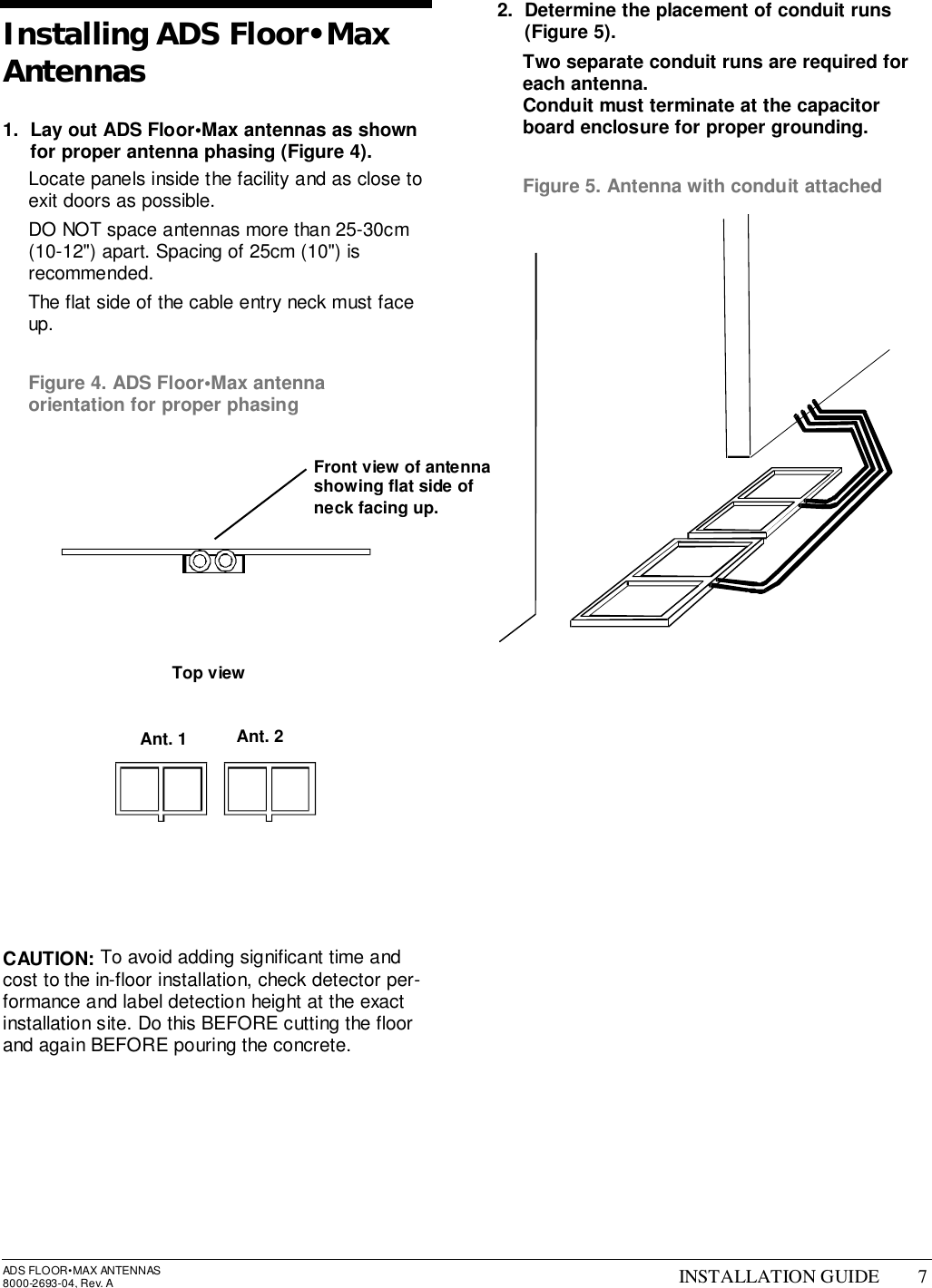
floor antenna install guide
![ADS FLOOR•MAX ANTENNAS8000-2693-04, Rev. A INSTALLATION GUIDE 5Figure 2. “On Grade” installation diagram Power packRemotealarm7.5m (25') maxConduit run10.5m (35') maxNo metal rebar or wire meshwithin 21cm (8") of bottom and 31cm (12") of sides of antenna25cm (10")PowerpackRemotealarmCap boardenclosureCap boardenclosure[a][b][a]RS232plateRS232plateAntennas (3cm (1.25") min to 5cm (2") max below surface of floor)3.98m (13' 1")1.29m(4' 3")[a] - 20cm (8") min[b] - 2m (7') max[c] - 25cm (10")[c]No. ofantennas Length ofexcavation1 2.18m (7' 2")2 3.98m (13' 1")3 5.80m (19' 0")4 7.61m (24' 11")](https://usermanual.wiki/Tyco-Safety-Sensormatic/UMADSNE.floor-antenna-install-guide/User-Guide-105254-Page-5.png)
![6 INSTALLATION GUIDE ADS FLOOR•MAX ANTENNAS8000-2693-04, REV. AFigure 3. “Off Grade” installation diagram 7.5m (25') maxConduit run10.5m (35') max1.14m(3' 9")3.93m (12' 11")PowerpackRemotealarmCap boardenclosure[a] - 20cm (8") min[b] - 2m (7') max[c] - 25cm (10")[a][b]RS232platePower packRemotealarm5cm (2")Cap boardenclosureRS232plate[c]ShieldtilesNo. ofantennas Length ofexcavation1 1.91m (6' 3")2 3.93m (12' 11")3 5.95m (19' 6")4 7.96m (26' 2")](https://usermanual.wiki/Tyco-Safety-Sensormatic/UMADSNE.floor-antenna-install-guide/User-Guide-105254-Page-6.png)