Tyco Safety Sensormatic UMADSNE Ultra Max Advanced Digital System User Manual pedestal install guide
Tyco Safety Products/Sensormatic Ultra Max Advanced Digital System pedestal install guide
Contents
- 1. Power pack install guide
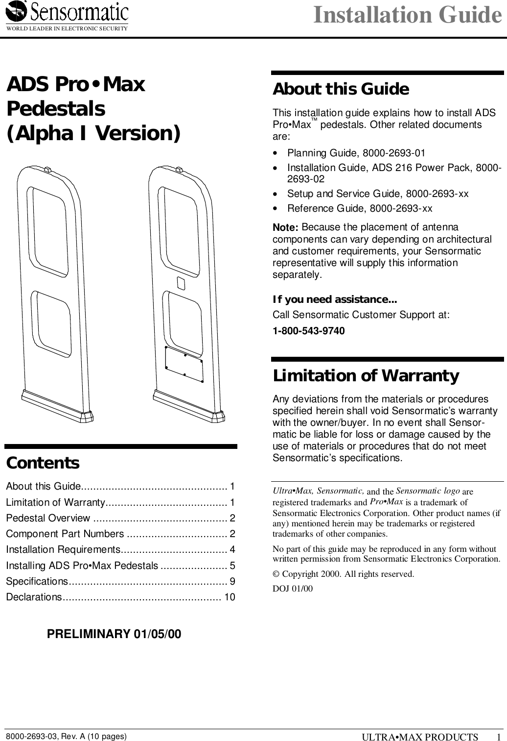
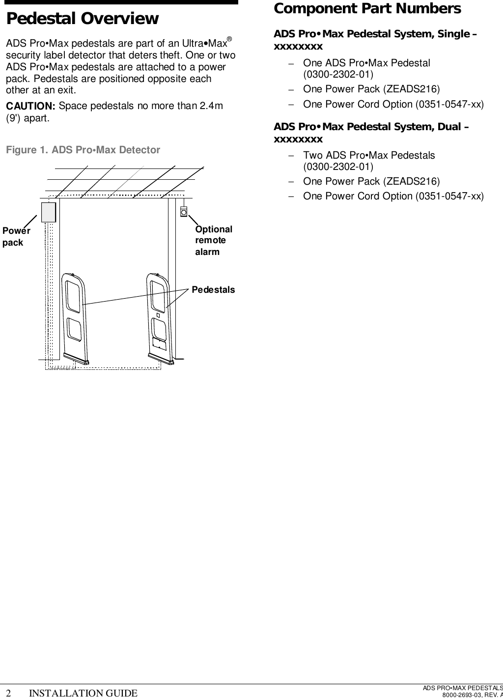
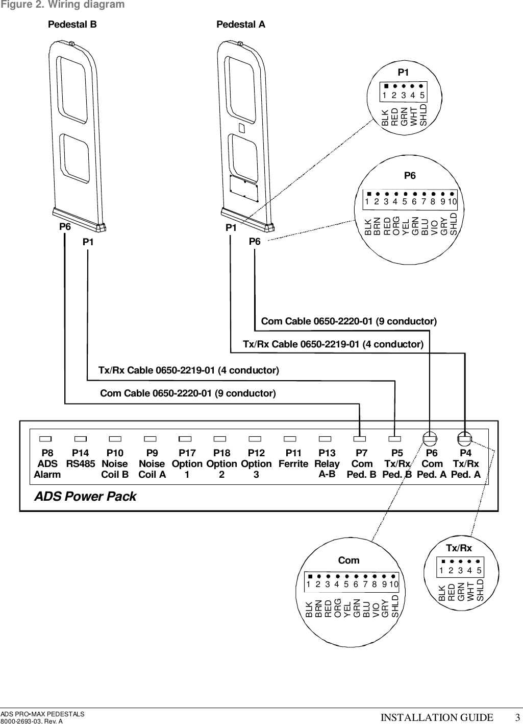
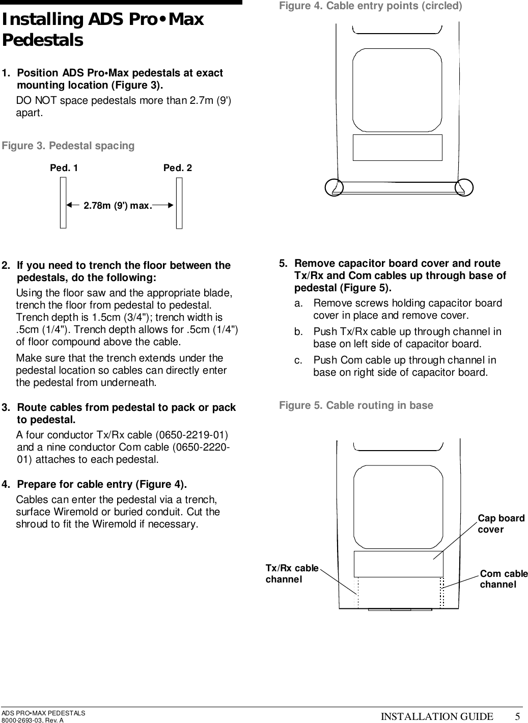
- 2. pedestal install guide
- 3. floor antenna install guide
- 4. users manual
pedestal install guide