Tyco Safety Sensormatic UMADSNE Anti Theft Device User Manual AMS 3000 Antenna installation guide
Tyco Safety Products/Sensormatic Anti Theft Device AMS 3000 Antenna installation guide
UserManual.wiki
>
Tyco Safety Sensormatic
>
UMADSNE User Manual
>
users manual
Contents
1.
Power pack install guide
2.
pedestal install guide
3.
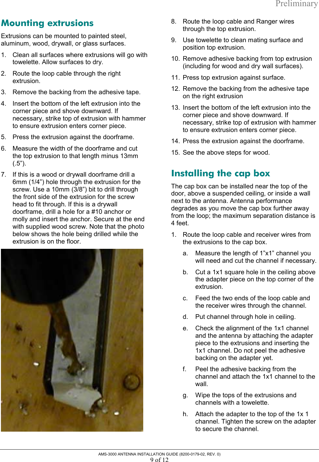
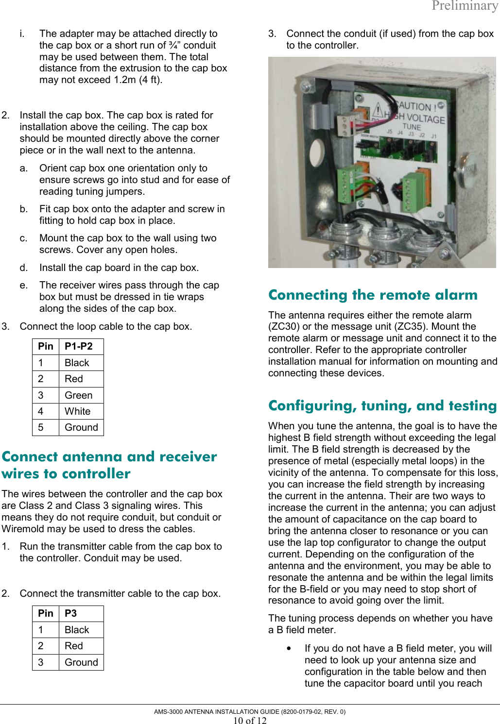
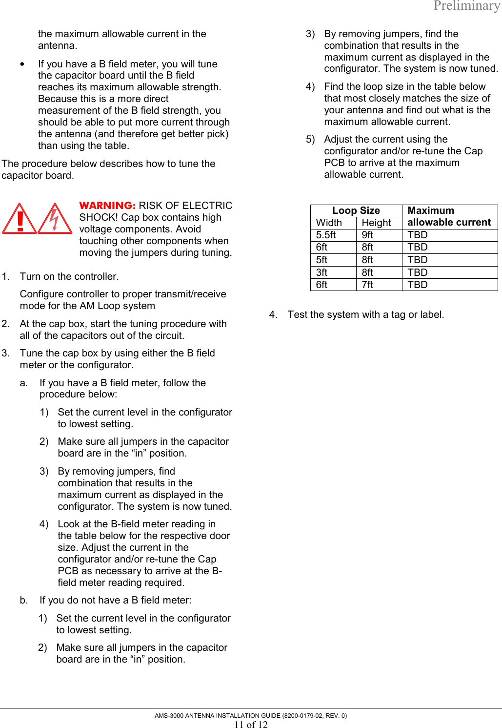
floor antenna install guide
4.
users manual
users manual
Navigation menu
Upload a User Manual
Namespaces
Wiki Guide
HTML
PDF
Info
Views
User Manual
Discussion / Help
Navigation