Tyco Safety Sensormatic UMADSNE Anti Theft Device User Manual AMS 3000 Antenna installation guide
Tyco Safety Products/Sensormatic Anti Theft Device AMS 3000 Antenna installation guide
Contents
users manual
Preliminary
AMS-3000 ANTENNA INSTALLATION GUIDE (8200-0179-02, REV. 0)
1 of 12
AMS-3000 Antenna
with Digital 216
Controller
Installation Guide
ZSLOOP
Contents
About this Guide ................................................ 1
About the Product .............................................. 1
Installation Requirements .................................. 2
Tools and Equipment Required .................. 3
Installation.......................................................... 3
Planning the installation .............................. 3
Installing the controller ................................ 4
Installing the equipment in the floor ............ 4
Preparing the extrusions ............................. 6
Mounting extrusions .................................... 9
Installing the cap box .................................. 9
Connect antenna and receiver wires to
controller.................................................... 10
Connecting the remote alarm.................... 10
Configuring, tuning, and testing ................ 10
Declarations..................................................... 12
Regulatory Compliance............................. 12
Other Declarations .................................... 12
© Sensormatic 2002
About this Guide
This installation guide explains how to install the
antennas and capacitor box for AMS-3000 systems
that use a Digital 216 controller. Other related
documents are:
• Planning Guide, 8200-0179-01
• Installation Guide, AMS-3000 Antenna with
Ultra*Post Plus Controller, 8200-0179-03
Note: Because customer requirements dictate the
placement of system components, your
Sensormatic representative will supply this
information separately.
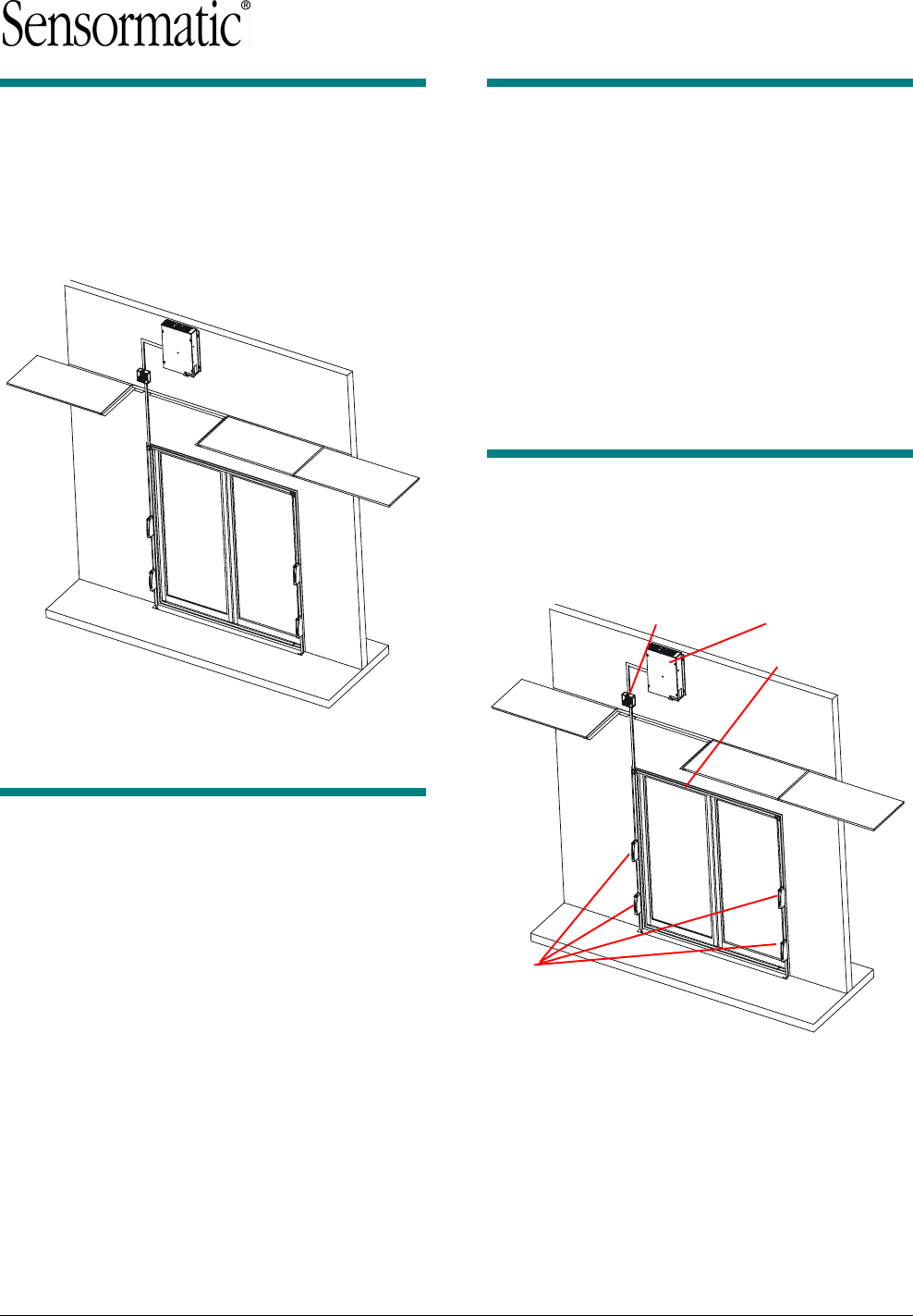
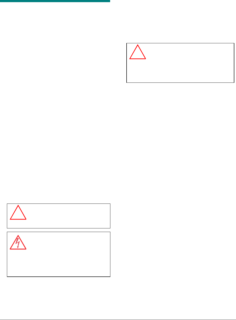
About the Product
The AMS-3000 system consists of an antenna
cable, three metal extrusions to house the cable, a
capacitor (cap) box, various connecting hardware,
and a set of receiver antennas.
Controller
Loop antenna
Cap box
Receive
r
Antennas
Preliminary
AMS-3000 ANTENNA INSTALLATION GUIDE (8200-0179-02, REV. 0)
2 of 12
Installation Requirements
Verifying Equipment and Unpacking
❑ Verify that all equipment has arrived. Make sure
the system configuration is the right one for the
installation site.
❑ Unpack major components in a back room. At
the install site, lay out parts in the order you will
need them. Do not clutter the aisle or cause a
trip hazard.
Note: The capacitor board is in a cardboard
sleeve taped to the bottom of the cardboard
antenna sleeve. The PVC leveling legs are
inside an envelope with the antenna.
Installer/Contractor
❑ Shall have electrical work comply with the
latest national electrical code, national fire
code, and all applicable local codes and
ordinances.
❑ Shall coordinate all work with other trades to
avoid interference.
❑ Shall verify existing site conditions and
coordinate with the owner’s representative and
appropriate utilities as required.
❑ Shall obtain copies of all related plans,
specifications, shop drawings and addenda to
schedule and coordinate related work.
❑ Shall thoroughly review the project to ensure
that all work meets or exceeds the above
requirements. Any alleged discrepancies shall
be brought to the attention of Sensormatic
Electronics.
!WARNING!
Do not install this product in hazardous
areas where highly combustible or
explosive products are stored or used.
WARNING—RISK OF ELECTRIC
SHOCK!
If the equipment must be left unattended
during installation, turn off the power or
cover high voltage components so that
no unauthorized person has access to
hazardous voltages.
Antenna Placement and Cabling
❑ Whenever possible, keep the antennas at least
2.4m (8') away from noise sources such as
computer monitors, TVs, switching power
supplies, and neon displays.
❑ Maximum cable distance from the AMS-3000
antenna to the capacitor board enclosure is
1.2m (4’). DO NOT splice antenna cables.
❑ Maximum cable distance from the controller to
the cap board enclosure is 12m 40’)
❑ Maximum cable distance from the receiver
antennas to the controller is 12m(40”)
!WARNING!
DO NOT compromise the structural
integrity of the floor by cutting or removing
rebar. Contractors must obtain approval for
all proposed structural changes. All
structural changes must meet national and
local requirements.
CAUTION: To avoid adding significant time and
cost to the in-floor installation, check detector per-
formance and label detection height at the exact
installation site. Do this BEFORE pouring the
concrete.
❑ All electrical work must comply with the
latest national electrical code, national fire
code, and all applicable local codes and
ordinances.
❑ High strength, non-metallic, non-shrink
mortar/concrete with a compressive strength of
5000 psi is required. (For example, FX-228
mortar mix and FX-752 bonding agent by Fox
Industries).
❑ Mortar cure time depends on the mix and
temperature of the mortar ingredients.
❑ Avoid walking on antenna cables during
installation.
❑ Heavy forklifts can pass over the mortar after 24
hours, provided the mortar is protected by
1.9cm (3/4") steel plates.
❑ Have on hand tools and equipment necessary
to place the mortar once it is mixed.
Cap Board Box
❑ Mount the cap board box as close to the
controller as possible. Maximum distance from
the controller to the cap box is 12m(40”)
❑ If conduit is not used for the cables between the
cap box and controller, use Romex connectors
wherever cables enter the controller and
capacitor board enclosure.

Preliminary
AMS-3000 ANTENNA INSTALLATION GUIDE (8200-0179-02, REV. 0)
3 of 12
Tools and Equipment Required
For all system installations:
• Plastic sheeting at least 0.15mm (6-mil) thick (to
protect nearby items from dust)
• Chalk or red permanent marker
• Floor saw
• PVC pipe cutter or hacksaw
• Hammer drill with 6.5mm (1/4") and 9.6mm
(3/8") masonry drill bits
• Power drill with 1.6mm (1/16"), 6.5mm (1/4"),
and 9.6mm (3/8") drill bits
• Hammer
• Phillips and slotted screwdrivers
• 14-16 AWG and 16-22 AWG wire strippers
• Ratchet and socket set
• Vacuum and broom
• Wet vacuum
• Level
• Electrical tape
• Teflon pipe tape
• Caution tape
• Duct tape
• Clear lacquer spray
Installation
To install the AMS-3000 antenna, perform the
following steps.
I. Plan the installation.
II. Perform a “tape up” to ensure system can
be installed.
III. Install the controller.
IV. Dig trench, install floor conduit, and feed
wires.
V. Prepare extrusions (drill holes, cut
extrusions, feed wires, and attach
Rangers).
VI. Attach extrusions and corner pieces
VII. Mount cap box, 1x1 channel (if necessary),
and route wires.
VIII. Connect antenna and receiver wires to
power pack and cap box.
IX. Mount remote alarm and connect.
X. Configure, tune, and test.
Planning the installation
Plan the placement of the controller, cap box,
receivers (Rangers), and the loop. See Planning
Guide for all details.
Controller restraints
• Determine whether the controller can be visible
to customers. If it must be hidden it can go
above a drop ceiling or in another room.
• Ensure the ranger cables will be long enough
to reach the controller.
• Ensure the transmitter (loop) cables will be
long enough to reach the controller.
• If you have multiple loops near each other,
resolve all antenna issues: one pack or two,
placement of controller to reach both antennas.
• Ensure the controller will be near a power
outlet.
Cap box restraints
• Determine whether the cap box will go above
the antenna or off to the side near the floor.
• Determine if the cap box can be visible or must
be hidden. If it must be hidden it can either go
above a drop ceiling or be mounted in a wall
off to the side of the antenna.
• Locate a suitable mounting surface (stud
location, grout lines).
• Ensure the cap box is within 1.2m(4ft) of the
loop.
Ranger restraints
• Ensure that the height of rangers does not
obstruct the operation of the door.
Loop restraints
• Determine whether the extrusions will go on
the store side of the doorframe or within the
arch of the doorframe.
• The only allowable configuration for the loop
antenna is an “L” shape, so ensure the
antenna can be routed in the floor in this way.
• Measure the height and width of the doorframe
to determine extrusion lengths.
• Keep loops on separate packs several feet
apart.
Preliminary
AMS-3000 ANTENNA INSTALLATION GUIDE (8200-0179-02, REV. 0)
4 of 12
• The dimensions of the exit door affect the
maximum amount of current in the loop and
the strength of the field it will generate. In
general, a smaller door can generate a
stronger B-field without exceeding regulatory
limits. Because larger door openings require a
stronger field to maintain pick ratios, you must
determine if the loop will work adequately for
an installation. Use the table below to
determine if the field strength will be sufficient
to give you the pick rate you need for the exit.
You may need to tape up an antenna before
installing the extrusions to help predict detector
performance.
Loop Size
Width Height
Maximum Allowed
Field Strength
5.5ft 9ft 12.9 A/m
6ft 8ft 13.1 A/m
5ft 8ft 17.6 A/m
3ft 8ft 17.9 A/m
6ft 7ft 14.6 A/m
Installing the controller
Refer to the appropriate controller installation
manual for instructions on installing the controller.
Performing a tape-up
It may be necessary to tape the antenna cable
around the door in the intended configuration prior
to installation to check for performance issues. This
is especially true for installations requiring a large
antenna loops or with metal doorframes. You
should tape the antenna cable in the intended
configuration, connect it to the controller, and then
check the current or field strength.
Installing the conduit in the
floor
The loop cable is installed beneath the surface of
the floor in ½” conduit. Note that ½” conduit
measures 2.13cm (.84”) in outside diameter.
1. If the doorframe and threshold are metal and
have no gap, remove the threshold and cut
6mm from the length of the threshold with a
saw.
2. Ensure there are no brackets underneath that
make contact to the threshold and the side
frames. If contact is made, make sure to
isolate such contacts.
3. Prepare the bottom run of loop cable. The
route of the cable depends on where the cap
box will be located and whether the antenna
goes on the store side of the doorframe or the
inside the arch of the doorframe.
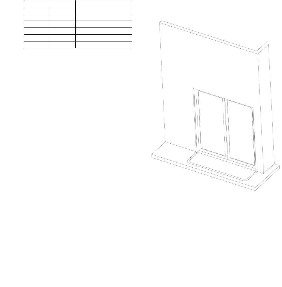
• If the cap box will be above the door
and the antenna goes on the store side
of the doorframe, assemble the floor
conduit and trace an outline on the floor as
shown below. Use a floor saw and chisel to
cut the 32mm (1.25”) deep trench in the
floor that is wide enough to accept 1/2”
conduit. Note that (½”) conduit measures
2.13cm (.84”) in outside diameter.
Preliminary
AMS-3000 ANTENNA INSTALLATION GUIDE (8200-0179-02, REV. 0)
5 of 12
• If the cap box will be above the door
and the antenna goes inside the
archway of the doorframe, assemble the
floor conduit and trace an outline on the
floor as shown below. Use a floor saw and
chisel to cut the 32mm (1.25”) deep trench
in the floor that is wide enough to accept
1/2” conduit. Note that (½”) conduit
measures 2.13cm (.84”) in outside
diameter.
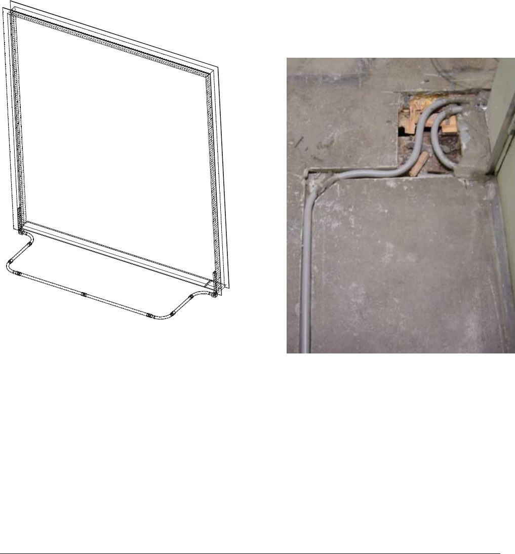
• If the cap box will be installed near the
floor, the trenching pattern is different.
Assemble the floor conduit, including the
section that routes the cable off to the side.
Trace an outline of the conduit on the floor.
Use a floor saw and chisel to cut the 31mm
(1.25”) deep trench in the floor that is wide
enough to accept 1.27cm (1/2”) conduit.
Note that ½” conduit measures 2.13cm
(.84”) in outside diameter. See the picture
below for an example of what the trench
looks like for an installation with the cap
box near the floor and the antenna
mounted on the store side of the
doorframe.
4. Reinstall the threshold if it was removed. Fill
the gap with RTV. Put ½” conduit in the
trenches.
5. Connect the conduit runs using the elbows
provided.
6. Connect the ½” conduit-to-extrusion adapters
to the ends of the conduit near the extrusions.
7. If the antenna will not be installed until a later
date, insert a dummy wire into the conduit to
facilitate antenna routing later. You should use
Yellow 77 or a similar wire-pulling lubricant to
ensure the wire can be pulled easily.
Preliminary
AMS-3000 ANTENNA INSTALLATION GUIDE (8200-0179-02, REV. 0)
6 of 12
Preparing the extrusions
1. Determine on which edge the Rangers will line
up: inside edge, outside edge, or on side of
extrusion. Lining up on the inside edge of the
doorframe is preferred. If a nearby wall or other
object prevents this, line the Rangers up on the
outside edge of the doorframe. Ensure that
arrows on all the Rangers point in the up
direction.
2. Measure length of vertical extrusion needed.
Remember to allow for length necessary for
insertion into corner piece in floor.
3. Cut extrusions to length. Make sure you cut the
bottom of the extrusion, not the end with the
tape indicating hole locations. Score the tape
before cutting.
4. To facilitate marking the extrusions for drilling,
a label has been provided in the extrusion to
show location and size of holes.
5. Prepare the right extrusion.
Note the two template labels at the bottom of
the extrusions. Use a center punch and punch
the center of the holes marked for the right
side “R”. Then drill through one surface with
drill size that comes closest to the hole
diameter on the template.
6. Prepare the left extrusion.
Same as right side, drill through holes marked
for left side “L”.
7. Prepare the top extrusion.
Cut the top extrusion to the proper length: the
width of the door minus .5”.
8. Install Rangers (ZKRANGER-2 only).
a. Find 91cm (36”) supplied wire in the kit.
(The interconnect wire included with the kit
is not long enough.)
Preliminary
AMS-3000 ANTENNA INSTALLATION GUIDE (8200-0179-02, REV. 0)
7 of 12
b. Run wire from lower ranger to upper
ranger lower hole. Note that you may have
to route wire through hole in Ranger to get
to other side.
c. Connect wires to bottom and top Ranger
per instructions in kit. (Bottom four-wire
connector on bottom to top two-wire
connectors on top).
d. Align notches for wires and edge of
Ranger with edge of extrusion.
e. Run wire from top of extrusion to top hole.
f. Connect wires to top Ranger.
g. Remove labels and using towelette, clean
surface of extrusions.
h. Remove backing from adhesive, align
Ranger to correct edge of extrusion, and
stick Ranger to extrusions.
Wire
routed
through
Ran
g
e
r
Preliminary
AMS-3000 ANTENNA INSTALLATION GUIDE (8200-0179-02, REV. 0)
8 of 12
i. Drill two 2.0mm(3/32”) holes through each
Ranger at each of the smaller notches.
j. Install two 8mm M4 screws through
Ranger and into extrusion. Do not use
screws in Ranger kit; they are too long.
k. Repeat steps for Rangers on other
extrusion. Note that notches for screws
may not be available and you will need to
drill hole in Ranger.
9. If the cap box will be installed above the door,
route the loop cable through the conduit in the
floor. Ensure that the adapter is in place at the
ends of the conduit. Also note that the section
of the loop cable coming out of the side
nearest the cap box should be shorter than the
section coming out the other side.
10. Route the loop cable through the left
extrusions.
11. Put the covers on the Rangers at the very end.
Preliminary
AMS-3000 ANTENNA INSTALLATION GUIDE (8200-0179-02, REV. 0)
9 of 12
Mounting extrusions
Extrusions can be mounted to painted steel,
aluminum, wood, drywall, or glass surfaces.
1. Clean all surfaces where extrusions will go with
towelette. Allow surfaces to dry.
2. Route the loop cable through the right
extrusion.
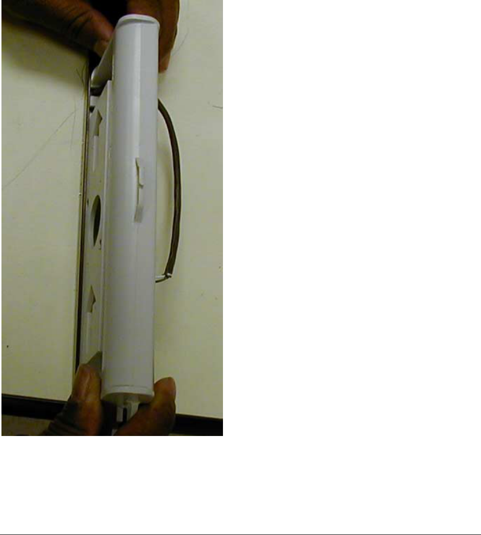
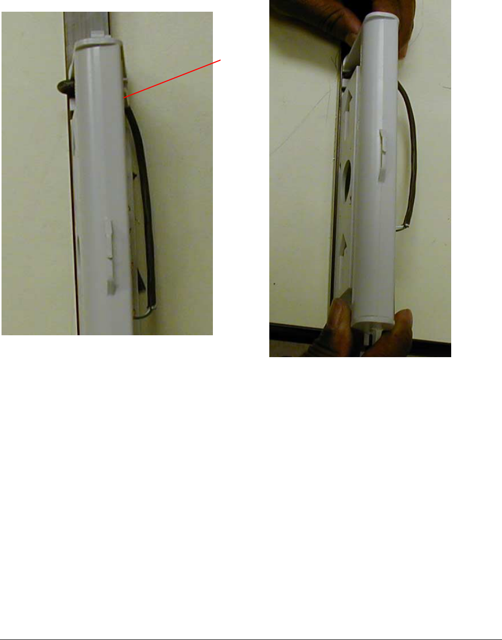
3. Remove the backing from the adhesive tape.
4. Insert the bottom of the left extrusion into the
corner piece and shove downward. If
necessary, strike top of extrusion with hammer
to ensure extrusion enters corner piece.
5. Press the extrusion against the doorframe.
6. Measure the width of the doorframe and cut
the top extrusion to that length minus 13mm
(.5”).
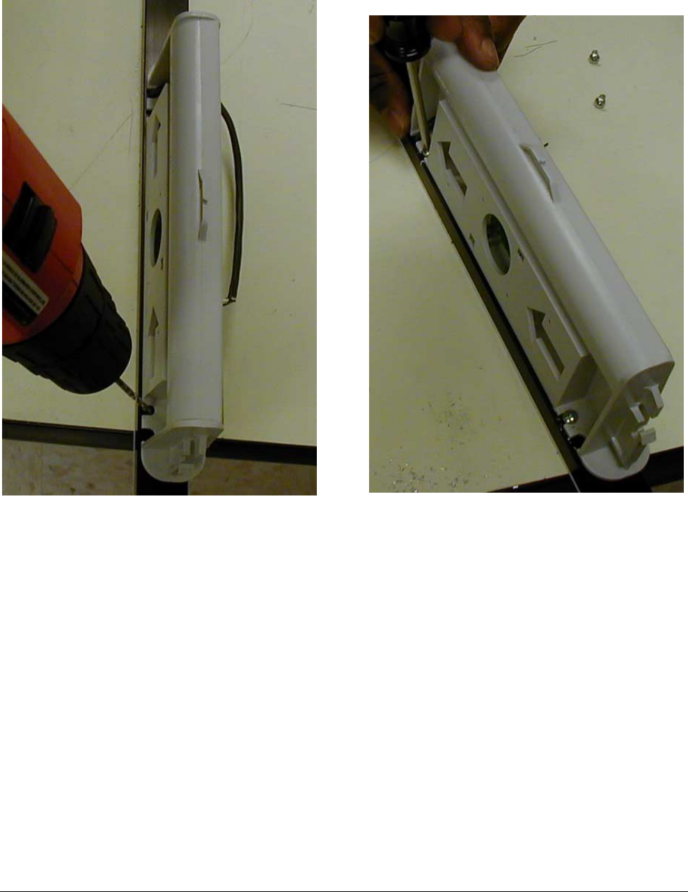
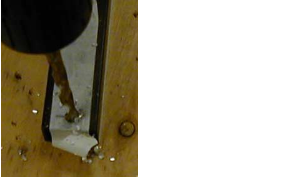
7. If this is a wood or drywall doorframe drill a
6mm (1/4”) hole through the extrusion for the
screw. Use a 10mm (3/8”) bit to drill through
the front side of the extrusion for the screw
head to fit through. If this is a drywall
doorframe, drill a hole for a #10 anchor or
molly and insert the anchor. Secure at the end
with supplied wood screw. Note that the photo
below shows the hole being drilled while the
extrusion is on the floor.
8. Route the loop cable and Ranger wires
through the top extrusion.
9. Use towelette to clean mating surface and
position top extrusion.
10. Remove adhesive backing from top extrusion
(including for wood and dry wall surfaces).
11. Press top extrusion against surface.
12. Remove the backing from the adhesive tape
on the right extrusion
13. Insert the bottom of the left extrusion into the
corner piece and shove downward. If
necessary, strike top of extrusion with hammer
to ensure extrusion enters corner piece.
14. Press the extrusion against the doorframe.
15. See the above steps for wood.
Installing the cap box
The cap box can be installed near the top of the
door, above a suspended ceiling, or inside a wall
next to the antenna. Antenna performance
degrades as you move the cap box further away
from the loop; the maximum separation distance is
4 feet.
1. Route the loop cable and receiver wires from
the extrusions to the cap box.
a. Measure the length of 1”x1” channel you
will need and cut the channel if necessary.
b. Cut a 1x1 square hole in the ceiling above
the adapter piece on the top corner of the
extrusion.
c. Feed the two ends of the loop cable and
the receiver wires through the channel.
d. Put channel through hole in ceiling.
e. Check the alignment of the 1x1 channel
and the antenna by attaching the adapter
piece to the extrusions and inserting the
1x1 channel. Do not peel the adhesive
backing on the adapter yet.
f. Peel the adhesive backing from the
channel and attach the 1x1 channel to the
wall.
g. Wipe the tops of the extrusions and
channels with a towelette.
h. Attach the adapter to the top of the 1x 1
channel. Tighten the screw on the adapter
to secure the channel.
Preliminary
AMS-3000 ANTENNA INSTALLATION GUIDE (8200-0179-02, REV. 0)
10 of 12
i. The adapter may be attached directly to
the cap box or a short run of ¾” conduit
may be used between them. The total
distance from the extrusion to the cap box
may not exceed 1.2m (4 ft).
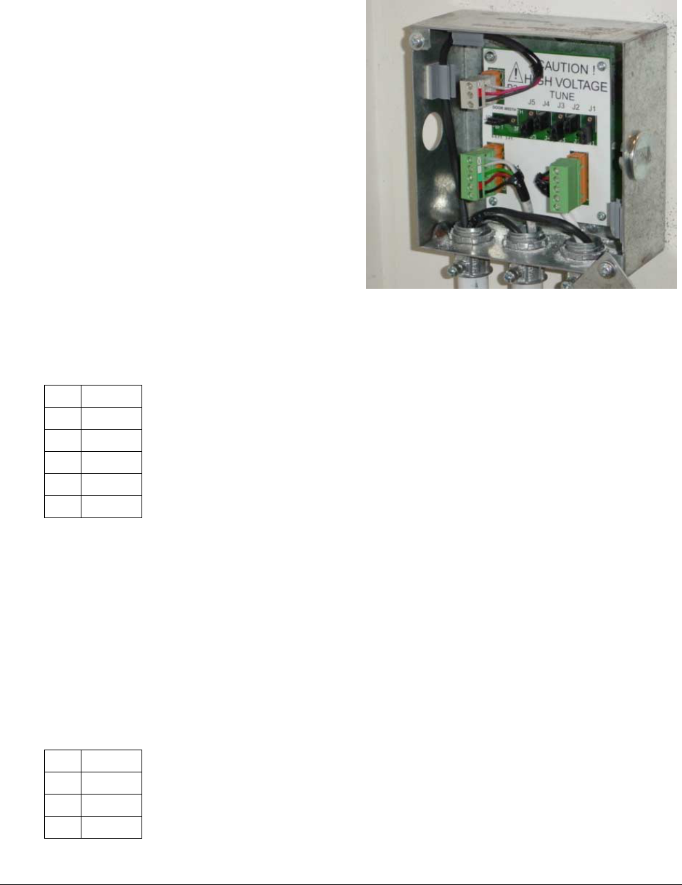
2. Install the cap box. The cap box is rated for
installation above the ceiling. The cap box
should be mounted directly above the corner
piece or in the wall next to the antenna.
a. Orient cap box one orientation only to
ensure screws go into stud and for ease of
reading tuning jumpers.
b. Fit cap box onto the adapter and screw in
fitting to hold cap box in place.
c. Mount the cap box to the wall using two
screws. Cover any open holes.
d. Install the cap board in the cap box.
e. The receiver wires pass through the cap
box but must be dressed in tie wraps
along the sides of the cap box.
3. Connect the loop cable to the cap box.
Pin P1-P2
1 Black
2 Red
3 Green
4 White
5 Ground
Connect antenna and receiver
wires to controller
The wires between the controller and the cap box
are Class 2 and Class 3 signaling wires. This
means they do not require conduit, but conduit or
Wiremold may be used to dress the cables.
1. Run the transmitter cable from the cap box to
the controller. Conduit may be used.
2. Connect the transmitter cable to the cap box.
Pin P3
1 Black
2 Red
3 Ground
3. Connect the conduit (if used) from the cap box
to the controller.
Connecting the remote alarm
The antenna requires either the remote alarm
(ZC30) or the message unit (ZC35). Mount the
remote alarm or message unit and connect it to the
controller. Refer to the appropriate controller
installation manual for information on mounting and
connecting these devices.
Configuring, tuning, and testing
When you tune the antenna, the goal is to have the
highest B field strength without exceeding the legal
limit. The B field strength is decreased by the
presence of metal (especially metal loops) in the
vicinity of the antenna. To compensate for this loss,
you can increase the field strength by increasing
the current in the antenna. Their are two ways to
increase the current in the antenna; you can adjust
the amount of capacitance on the cap board to
bring the antenna closer to resonance or you can
use the lap top configurator to change the output
current. Depending on the configuration of the
antenna and the environment, you may be able to
resonate the antenna and be within the legal limits
for the B-field or you may need to stop short of
resonance to avoid going over the limit.
The tuning process depends on whether you have
a B field meter.
• If you do not have a B field meter, you will
need to look up your antenna size and
configuration in the table below and then
tune the capacitor board until you reach
Preliminary
AMS-3000 ANTENNA INSTALLATION GUIDE (8200-0179-02, REV. 0)
11 of 12
the maximum allowable current in the
antenna.
• If you have a B field meter, you will tune
the capacitor board until the B field
reaches its maximum allowable strength.
Because this is a more direct
measurement of the B field strength, you
should be able to put more current through
the antenna (and therefore get better pick)
than using the table.
The procedure below describes how to tune the
capacitor board.
WARNING: RISK OF ELECTRIC
SHOCK! Cap box contains high
voltage components. Avoid
touching other components when
moving the jumpers during tuning.
1. Turn on the controller.
Configure controller to proper transmit/receive
mode for the AM Loop system
2. At the cap box, start the tuning procedure with
all of the capacitors out of the circuit.
3. Tune the cap box by using either the B field
meter or the configurator.
a. If you have a B field meter, follow the
procedure below:
1) Set the current level in the configurator
to lowest setting.
2) Make sure all jumpers in the capacitor
board are in the “in” position.
3) By removing jumpers, find
combination that results in the
maximum current as displayed in the
configurator. The system is now tuned.
4) Look at the B-field meter reading in
the table below for the respective door
size. Adjust the current in the
configurator and/or re-tune the Cap
PCB as necessary to arrive at the B-
field meter reading required.
b. If you do not have a B field meter:
1) Set the current level in the configurator
to lowest setting.
2) Make sure all jumpers in the capacitor
board are in the “in” position.
3) By removing jumpers, find the
combination that results in the
maximum current as displayed in the
configurator. The system is now tuned.
4) Find the loop size in the table below
that most closely matches the size of
your antenna and find out what is the
maximum allowable current.
5) Adjust the current using the
configurator and/or re-tune the Cap
PCB to arrive at the maximum
allowable current.
Loop Size
Width Height
Maximum
allowable current
5.5ft 9ft TBD
6ft 8ft TBD
5ft 8ft TBD
3ft 8ft TBD
6ft 7ft TBD
4. Test the system with a tag or label.
!

Preliminary
AMS-3000 ANTENNA INSTALLATION GUIDE (8200-0179-02, REV. 0)
12 of 12
Declarations
Regulatory Compliance
Emissions .......................... 47 CFR, Part 15
RSS 210
Safety UL1950
CSA C22.2 No 950
EN 60 950
FCC COMPLIANCE: This equipment complies with Part 15
of the FCC rules for intentional radiators and Class A digital
devices when installed and used in accordance with the
instruction manual. Following these rules provides reasonable
protection against harmful interference from equipment
operated in a commercial area. This equipment should not be
installed in a residential area as it can radiate radio frequency
energy that could interfere with radio communications, a
situation the user would have to fix at their own expense.
EQUIPMENT MODIFICATION CAUTION: Equipment
changes or modifications not expressly approved by
Sensormatic Electronics Corporation, the party responsible for
FCC compliance, could void the user's authority to operate the
equipment and could create a hazardous condition.
Other Declarations
WARRANTY DISCLAIMER: Sensormatic Electronics
Corporation makes no representation or warranty with respect
to the contents hereof and specifically disclaims any implied
warranties of merchantability or fitness for any particular
purpose. Further, Sensormatic Electronics Corporation
reserves the right to revise this publication and make changes
from time to time in the content hereof without obligation of
Sensormatic Electronics Corporation to notify any person of
such revision or changes.
LIMITED RIGHTS NOTICE: For units of the Department
of Defense, all documentation and manuals were developed at
private expense and no part of it was developed using
Government Funds. The restrictions governing the use and
disclosure of technical data marked with this legend are set
forth in the definition of “limited rights” in paragraph (a) (15)
of the clause of DFARS 252.227.7013. Unpublished - rights
reserved under the Copyright Laws of the United States.
TRADEMARK NOTICE: Sensormatic and the Sensormatic
logo are trademarks or registered trademarks of Sensormatic
Electronics Corporation. Wiremold is a registered trademark
of the Wiremold Company. Other product names mentioned
herein may be trademarks or registered trademarks of
Sensormatic or other companies.
No part of this guide may be reproduced in any form without
written permission from Sensormatic Electronics Corporation.
RWH 07/02