Tyco Safety Sensormatic UMADSNE Ultra Max Advanced Digital System User Manual Power pack install guide
Tyco Safety Products/Sensormatic Ultra Max Advanced Digital System Power pack install guide
Contents
- 1. Power pack install guide
- 2. pedestal install guide
- 3. floor antenna install guide
- 4. users manual
Power pack install guide
WORLD LEADER IN ELECTRONIC SECURITY Installation Guide
8000-2693-02, Rev. A (8 pages) ULTRA•MAX PRODUCTS 1
1 ADS 216 Power Pack
Contents
About this Guide................................................ 1
Limitation of Warranty........................................ 1
Power Pack Overview........................................ 2
Installation Requirements................................... 2
Installing the Power Pack................................... 3
Connecting the Alarm Cable............................... 4
Connecting Power to the Power Pack................. 5
Specifications.................................................... 7
Declarations...................................................... 8
About this Guide
This installation guide explains how to install the
ADS 216 Power Pack. Other related documents
are:
• Planning Guide, 8000-2693-01
• Installation Guide, ADS Pro•Max Pedestals,
8000-2693-03
• Installation Guide, ADS Floor•Max Antennas,
8000-2693-03
• Setup and Service Guide, 8000-2693-xx
• Reference Guide, 8000-2693-xx
Note: Because placement of system components
depends on architectural and customer require-
ments, your Sensormatic representative will supply
this information separately.
If you need assistance...
Call Sensormatic Customer Support at:
1-800-543-9740
Limitation of Warranty
Any deviations from the materials or procedures
specified herein shall void Sensormatic's warranty
with the owner/buyer. In no event shall Sensor-
matic be liable for loss or damage caused by the
use of materials or procedures that do not meet
Sensormatic's specifications.
Ultra•Max, Sensormatic, and the Sensormatic logo are
registered trademarks of Sensormatic Electronics Corporation.
Other product names (if any) mentioned herein may be
trademarks or registered trademarks of other companies.
No part of this guide may be reproduced in any form without
written permission from Sensormatic Electronics Corporation.
© Copyright 2000. All rights reserved.
DOJ 01/00
PRELIMINARY – 01/05/00
2 INSTALLATION GUIDE ADS 216 POWER PAC
K
8000-2693-02, REV.
A
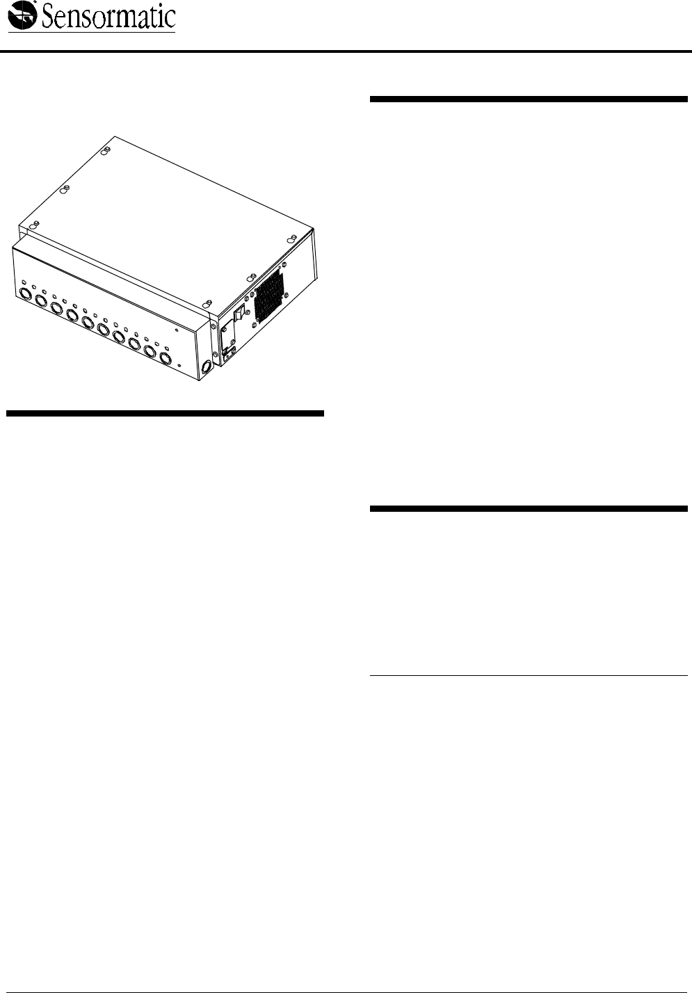
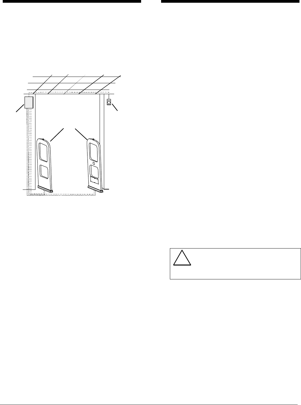
Power Pack Overview
The ADS 216 Power Pack is part of an Ultra•Max
security label detector. The power pack controls
up to two transceiver antennas and two remote
alarms.
Figure 1. Ultra•Max Detector
The ADS 216 Power Pack, ZEADS216 (Non-
European) ships with the antennas or can be
ordered separately.
Installation Requirements
Verifying Equipment and
Unpacking
❑ Verify that all equipment has arrived. Make
sure the system configuration is the right one
for the installation site.
❑ Unpack major components in a back room. At
the install site, lay out parts in the order you will
need them. Do not clutter the aisle or cause a
trip hazard.
Installer/Contractor
❑ Shall have electrical work comply with the
latest national electrical code, national fire
code, and all applicable local codes and
ordinances.
❑ Shall coordinate all work with other trades to
avoid interference.
❑ Shall verify existing site conditions and
coordinate with the owner’s representative and
appropriate utilities as required.
❑ Shall obtain copies of all related plans,
specifications, shop drawings and addenda to
schedule and coordinate related work.
❑ Shall thoroughly review the project to ensure
that all work meets or exceeds the above
requirements. Any alleged discrepancies shall
be brought to the attention of Sensormatic
Electronics.
!WARNING!
Do not install this product in hazardous
areas where highly combustible or
explosive products are stored or used.
Electrical Requirements
❑ Connect the pack to a 100-120Vac or 220-
240Vac source. No fuse exchange is required
for the power pack.
❑ The ac source must be unswitched with less
than 0.5Vac between neutral and ground.
❑ DO NOT share the ac source with neon signs,
motors, computers, cash registers, terminals,
or data communications equipment.
❑ DO NOT use orange-colored outlets dedicated
for computer equipment.
Power
pack
Optional
remote
alarm
Antennas
ADS 216 POWER PACK
8000-2693-02, Rev. A INSTALLATION GUIDE 3
Power Pack
❑ The pack can be placed on a shelf or mounted
on a wall. The pack can be hidden in a remote
location such as checkout counter, back room,
or basement.
❑ Provide a minimum of 20cm (8") of
unobstructed space around the pack for
ventilation.
❑ Use the appropriate power cord based on the
country of use.
USA-IEC 320, 18/3, 125V, 10A, 7.5ft. 0351-0547-01
Schuko-IEC 320, 1mm sq., 250V, 10A, 2.5m 0351-0547-02
UK-IEC 320, 1mm sq., 250V, 10A, 2.5m 0351-0547-03
Japan-IEC 320, 2mm sq., 250V, 15A, 2.5m 0351-0547-04
US-Filter, Line, 125V, 6A, Plug-in 0351-0547-05
Australia to IEC 320, 2.5m, 250V, 10A 0351-0547-07
❑ Replace the pack’s slow-blow fuses only with a
fuse of the same type and rating.
❑ Maximum cable distance from the antennas to
the power pack is 12.2m (40').
ZC30-XP/ZC35-XP
Remote Alarm Unit (if used)
❑ Plug the transformer used to power the alarm
into a 24-hour, unswitched outlet.
❑ Maximum cable distance from the power pack
to each alarm unit is about 7.6m (25').
Tools and Equipment Required
For all system installations:
• 6 mil (minimum) plastic sheeting (to protect
nearby items from dust)
• Permanent marker and/or pencil
• Hammer drill with 6.5mm (1/4") and 9.6mm
(3/8") masonry drill bits
• Power drill with 1.6mm (1/16"), 6.5mm (1/4"),
and 9.6mm (3/8") drill bits
• Hammer
• Phillips and slotted screwdrivers
• Ratchet and socket set
• Vacuum and broom
Installing the Power Pack
The pack can rest on a shelf (no mounting
procedure required) or can be hung on a wall.
To mount the pack on a wall, proceed to the
section “Wall-mounting the Power Pack” on
page 3.
Otherwise, go to “Connecting the Alarm Cable”
on page 4.
Wall-mounting the Power Pack
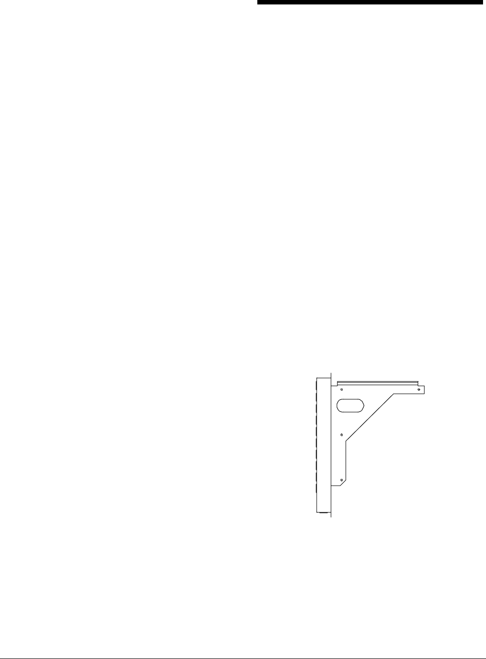
1. Attach the bracket to the wall (Figure 2).
The pack can be mounted on studs using
screws or on wall-board using screws and
anchors.
a. Position wall-mount bracket and level it to
mark the mounting hole locations. Remove
the bracket.
b. If mounting on wall-board, drill four holes
for hollow wall (wall-board) anchors. Tap
anchors (not shown) into holes.
c. With its lip facing upward, secure the
bracket to the wall with four screws. The
screws are suitable for use in wood or
metal.
Figure 2. Attaching the bracket to the wall
4 INSTALLATION GUIDE ADS 216 POWER PAC
K
8000-2693-02, REV.
A
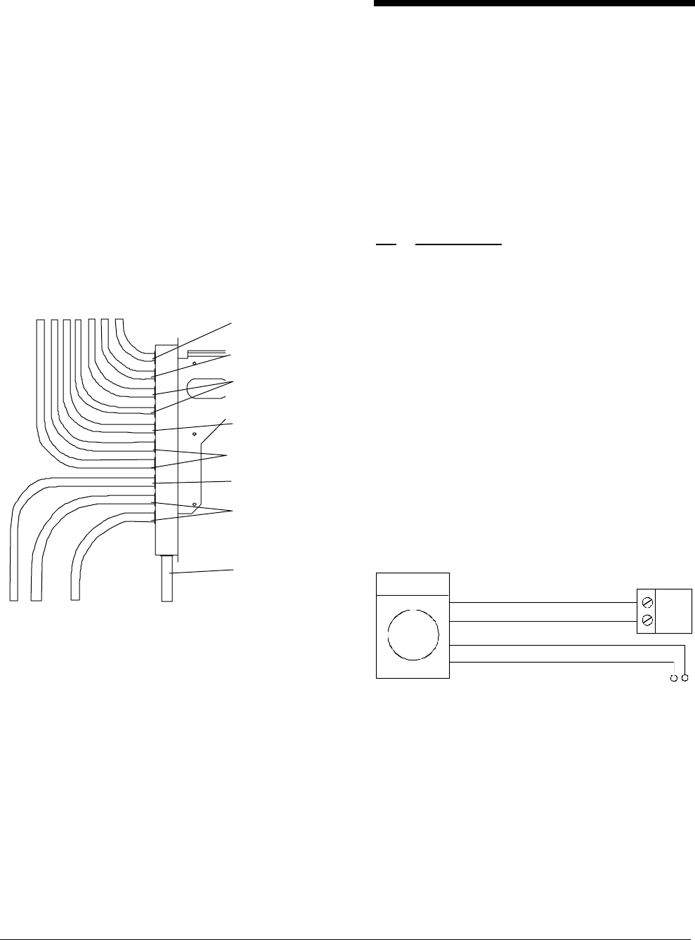
2. If using conduit, attach conduit to bracket.
The power pack bracket provides ten ½" or ¾"
knockouts for antenna and alarm cables and
one ½” or ¾” knockout for hardwired AC power.
Refer to Figure 6.
Antenna Tx/Rx and Com cables attach to
connectors in the lower corner of the power
pack. The remote alarm cable attaches to a
connector above the antenna cable connectors.
Select knockouts closest to the power pack
connectors for the cables and attach conduit.
Maximum conduit attachment is shown in
Figure 3. Several cables can share conduit as
long as conduit fill does not exceed 50 percent.
Figure 3. Maximum conduit attachment
3. Mount the pack to the bracket.
a. Rest the lip of the pack’s mounting bracket
on the lip of the wall-mounted bracket.
b. Slide pack to left until pack butts up against
wall-mounted bracket.
4. After cable connections are complete,
attach bracket to power pack using two
screws at each end of bracket.
Mounting the power pack is complete. Go to
“Connecting the Alarm Cable” on page 4.
Connecting the Alarm Cable
The power pack can trigger up to two remote
alarms.
To connect remote alarms, continue.
Otherwise, go to “Connecting Power to the
Power Pack” on page 5.
Connect the remote alarm to the Relay A-B alarm
receptacle of the power pack (Figure 6).
Relay A-B pin assignments are as follows:
Pin Relay Output
1 Relay A Arm
2 Relay B N.C.
3 Relay C N.O.
4 Shield
5 Not used
6 Relay B Arm.
7 Relay B N.C.
8 Relay B N.O.
9 Shield
For example, connect the remote alarm controlled
by relay 1 to pins 1, 2, and 3. Refer to Figure 4 for
remote alarm wiring.
Figure 4. Remote alarm wiring
Pin 1 - black
Pin 4 - red
Relay
A-B
pin 1 pin 3
or
pin 6 pin 8
Transformer
Remote
alarm
(ZC30/ZC35)
COM
17V
Pin 2 - green
Pin 3 - white
Alarm
RS485
Noise Coil
A and B
Option
SkyMax A and B
Relay A-B
Antenna A and B
AC power
ADS 216 POWER PACK
8000-2693-02, Rev. A INSTALLATION GUIDE 5
Connecting Power to the
Power Pack
!For installation using a line cord, the
socket-outlet must be installed near
the equipment and at a location which
is easily accessible.
Für Installationen mit einem
Stromkabel muß die Steckdose an
einem Standort installiert werden,
welcher einfachen Zugang erlaubt.
!A 6A, 2 pole, ganged disconnect
device, which also provides short
circuit and overload protection, and
has a minimum 3mm open circuit
clearance, in accordance with the
National Electric Code and applicable
local codes must be installed by a
licensed electrician at a location
readily accessible to the equipment.
Ein 6A, 2-poliges, gekoppeltes Ausschalt-
gerät, welches auch über einen
Kurzschluß- sowie Überbelastungsschutz
verfügt, und einen minimum 3mm offenen
Schaltabstand aufweist, nach
Übereinstimmung mit den Nationalen
Elektrischen Regelungen sowie lokalen
Regeln, muß an einem Standort installiert
werden, welcher einfachen Zugang zum
Gerät erlaubt.
The AC power source can be 100-120Vac or 220-
240Vac. The power supply automatically senses
the voltage so no jumper settings are required.
AC power can be hardwired to the power pack or
connected by an ac power cord.
WARNING—RISK OF ELECTRIC
SHOCK!
The AC power line could be carrying
120Vac or 240Vac.
If ac power is connected by a power cord, remove
the metal cover over the IEC connector (Figure 6)
and attach the power cord.
If ac power is hardwired, do the following:
1. Route power cable through knockout on
corner of power pack (Figure 6).
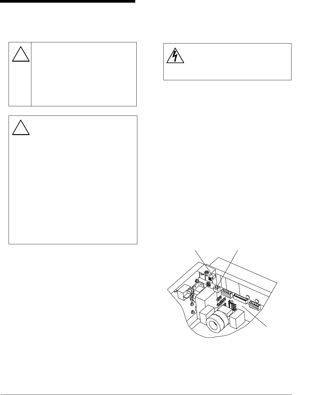
2. Using a small screwdriver, connect the ac
power wires (line, neutral) to the two-pin
connector in terminal P2. Connect white to
pin 1 (neutral); connect black to pin 2 (line).
Refer to Figure 5.
3. Plug the two-pin connector into pluggable
terminal P2 on the backplane board.
4. Connect green to ground on the power pack
chassis.
Figure 5. Hardwired AC power connection
Hardwired AC:
P2: pin 1 – neutral (white)
P2: pin 2 – line (black)
AC ground (green)
Backplane
board
6 INSTALLATION GUIDE ADS 216 POWER PAC
K
8000-2693-02, REV.
A
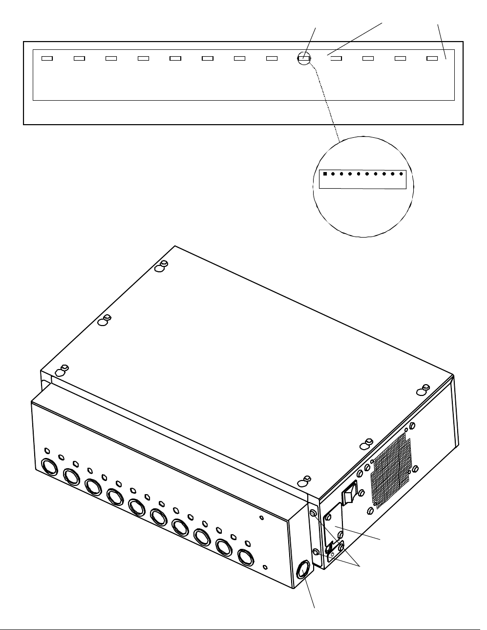
Figure 6. Power pack connections
P4
Tx/Rx
Ped. A
P6
Com
Ped. A
P5
Tx/Rx
Ped. B
P7
Com
Ped. B
P13
Relay
A-B
P11
Ferrite
P12
Option
3
P18
Option
2
P17
Option
1
P9
Noise
Coil A
P10
Noise
Coil B
P14
RS485
P8
ADS
Alarm
ADS Power Pack
Rela
y
A-B
1 2 3 4 5 6 7 8 9 10
ARM A
NC A
NO A
SHLD
ARM B
NC B
NO B
SHLD
IEC connector cover
Knockout for hardwired AC
Remote alarm
connector Antenna
connectors
Bracket to pack
mounting screws
(
two at each end
)

ADS 216 POWER PACK
8000-2693-02, Rev. A INSTALLATION GUIDE 7
Specifications
Electrical
Power Supply (Non-European Power Pack)
Primary Input: ...................100-120Vac or
220-240Vac
@ 50–60Hz
Primary Power Fuse:.........5A, 250V slo-blow
Current Draw: ...................2.0A peak
Input Power: .....................<180W
Transmitter
Outputs:............................2 ports (two antennas,
multiplexed)
Operating Frequency:........58, 60, or 68kHz
(±200Hz)
Transmit Burst Duration.....1.6ms
Transmit Current: ..............16A peak
Burst Repetition Rate:
Based on 50Hz ac.............37.5Hz (Normal)
75Hz (Validation)
Based on 60Hz ac.............45Hz (Normal)
90Hz (Validation)
Receiver
Inputs:..............................2 ports (two antennas,
multiplexed)
Center Frequency:.............58, 60, or 68kHz
Receive Coil Resistance:...1.6 ohms (±5%)
Alarm
Alarm Relay Output...........DPDT contacts
Contact Switching Current .1.0A max.
Contact Switching Voltage .28V max.
Lamp/Audio Duration.........1–30 sec.
(1 sec. increments)
Environmental
Ambient Temperature:.......0°C to 50°C
(32°F to 122°F)
Relative Humidity:.............0 to 90%
non-condensing
Mechanical
Power Pack
Length..............................50.7cm (20")
Width with bracket.............37.7cm (14.8")
Width without bracket........32.6cm (12.8")
Height ..............................15cm (5.9")
Weight..............................kg (lbs.)
Remote Alarm / Message Unit
Height ..............................20.3cm (8")
Length..............................15cm (5.9")
Width................................6.4cm (2.5")

8 INSTALLATION GUIDE ADS 216 POWER PAC
K
8000-2693-02, REV.
A
Declarations
Regulatory Compliance (Non-
European Power Pack)
Safety:............................UL 1950
Can/CSA C22.2
No. 950
EMC:..............................47 CFR, Part 15
FCC COMPLIANCE: This equipment complies with Part
15 of the FCC rules for intentional radiators and Class A
digital devices when installed and used in accordance with the
instruction manual. Following these rules provides reasonable
protection against harmful interference from equipment
operated in a commercial area. This equipment should not be
installed in a residential area as it can radiate radio frequency
energy that could interfere with radio communications, a
situation the user would have to fix at their own expense.
EQUIPMENT MODIFICATION CAUTION: Equipment
changes or modifications not expressly approved by
Sensormatic Electronics Corporation, the party responsible for
FCC compliance, could void the user's authority to operate the
equipment and could create a hazardous condition.
Other Declarations
WARRANTY DISCLAIMER: Sensormatic Electronics
Corporation makes no representation or warranty with respect
to the contents hereof and specifically disclaims any implied
warranties of merchantability or fitness for any particular
purpose. Further, Sensormatic Electronics Corporation
reserves the right to revise this publication and make changes
from time to time in the content hereof without obligation of
Sensormatic Electronics Corporation to notify any person of
such revision or changes.
LIMITED RIGHTS NOTICE: For units of the Department
of Defense, all documentation and manuals were developed at
private expense and no part of it was developed using
Government Funds. The restrictions governing the use and
disclosure of technical data marked with this legend are set
forth in the definition of "limited rights" in paragraph (a) (15)
of the clause of DFARS 252.227.7013. Unpublished - rights
reserved under the Copyright Laws of the United States.