Tyco Safety Sensormatic UMADSNE Ultra Max Advanced Digital System User Manual pedestal install guide
Tyco Safety Products/Sensormatic Ultra Max Advanced Digital System pedestal install guide
Contents
- 1. Power pack install guide
- 2. pedestal install guide
- 3. floor antenna install guide
- 4. users manual
pedestal install guide
WORLD LEADER IN ELECTRONIC SECURITY Installation Guide
8000-2693-03, Rev. A (10 pages) ULTRA•MAX PRODUCTS 1
1 ADS Pro•Max
Pedestals
(Alpha I Version)
Contents
About this Guide................................................ 1
Limitation of Warranty........................................ 1
Pedestal Overview ............................................ 2
Component Part Numbers ................................. 2
Installation Requirements................................... 4
Installing ADS Pro•Max Pedestals ...................... 5
Specifications.................................................... 9
Declarations.................................................... 10
About this Guide
This installation guide explains how to install ADS
Pro•Max™ pedestals. Other related documents
are:
• Planning Guide, 8000-2693-01
• Installation Guide, ADS 216 Power Pack, 8000-
2693-02
• Setup and Service Guide, 8000-2693-xx
• Reference Guide, 8000-2693-xx
Note: Because the placement of antenna
components can vary depending on architectural
and customer requirements, your Sensormatic
representative will supply this information
separately.
If you need assistance...
Call Sensormatic Customer Support at:
1-800-543-9740
Limitation of Warranty
Any deviations from the materials or procedures
specified herein shall void Sensormatic’s warranty
with the owner/buyer. In no event shall Sensor-
matic be liable for loss or damage caused by the
use of materials or procedures that do not meet
Sensormatic’s specifications.
Ultra•Max, Sensormatic, and the Sensormatic logo are
registered trademarks and Pro•Max is a trademark of
Sensormatic Electronics Corporation. Other product names (if
any) mentioned herein may be trademarks or registered
trademarks of other companies.
No part of this guide may be reproduced in any form without
written permission from Sensormatic Electronics Corporation.
© Copyright 2000. All rights reserved.
DOJ 01/00
PRELIMINARY 01/05/00
2 INSTALLATION GUIDE ADS PRO•MAX PEDESTAL
S
8000-2693-03, REV.
A
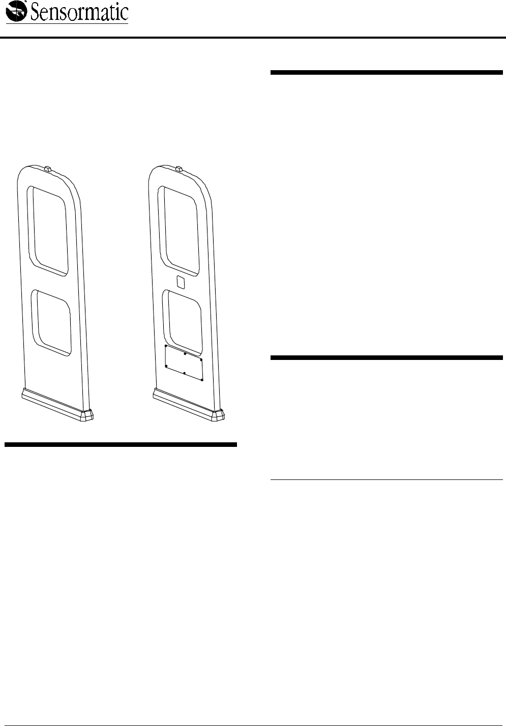
Pedestal Overview
ADS Pro•Max pedestals are part of an Ultra•Max®
security label detector that deters theft. One or two
ADS Pro•Max pedestals are attached to a power
pack. Pedestals are positioned opposite each
other at an exit.
CAUTION: Space pedestals no more than 2.4m
(9') apart.
Figure 1. ADS Pro•Max Detector
Component Part Numbers
ADS Pro•Max Pedestal System, Single –
xxxxxxxx
− One ADS Pro•Max Pedestal
(0300-2302-01)
− One Power Pack (ZEADS216)
− One Power Cord Option (0351-0547-xx)
ADS Pro•Max Pedestal System, Dual –
xxxxxxxx
− Two ADS Pro•Max Pedestals
(0300-2302-01)
− One Power Pack (ZEADS216)
− One Power Cord Option (0351-0547-xx)
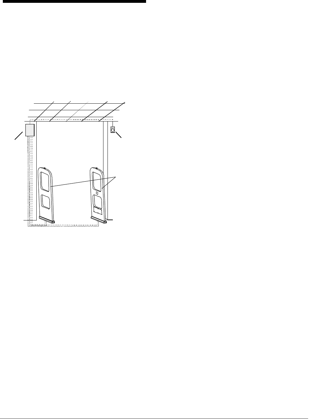
Power
pack
Optional
remote
alarm
Pedestals
ADS PRO•MAX PEDESTALS
8000-2693-03, Rev. A INSTALLATION GUIDE 3
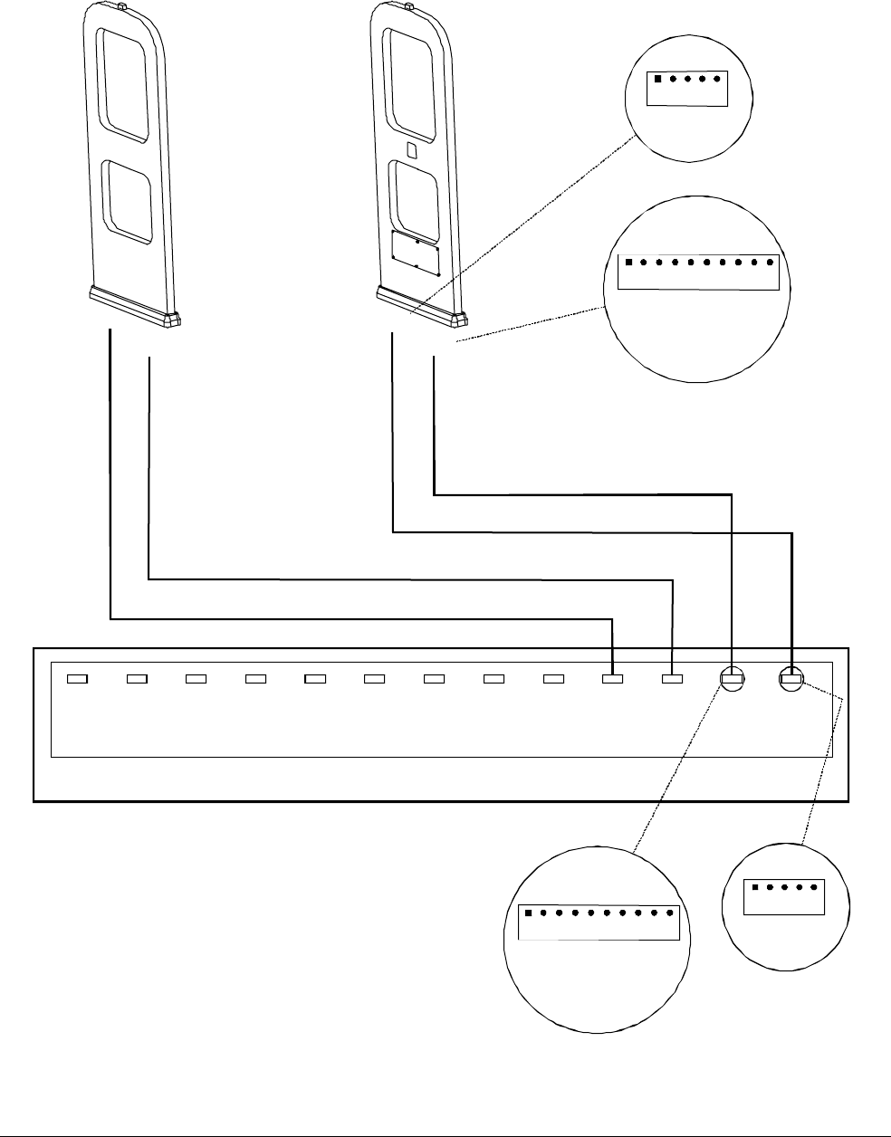
Figure 2. Wiring diagram
Com Cable 0650-2220-01
(
9 conductor
)
P4
Tx/Rx
Ped. A
P6
Com
Ped. A
P5
Tx/Rx
Ped. B
P7
Com
Ped. B
P13
Relay
A-B
P11
Ferrite
P12
Option
3
P18
Option
2
P17
Option
1
P9
Noise
Coil A
P10
Noise
Coil B
P14
RS485
P8
ADS
Alarm
ADS Power Pack
BLK
RED
GRN
WHT
SHLD
Tx/Rx
1 2 3 4 5
Com
1 2 3 4 5 6 7 8 9 10
BLK
BRN
RED
ORG
YEL
GRN
BLU
VIO
GRY
SHLD
Pedestal A
BLK
RED
GRN
WHT
SHLD
P1
1 2 3 4 5
P6
1 2 3 4 5 6 7 8 9 10
BLK
BRN
RED
ORG
YEL
GRN
BLU
VIO
GRY
SHLD
Pedestal B
Tx/Rx Cable 0650-2219-01 (4 conductor)
Com Cable 0650-2220-01 (9 conductor)
Tx/Rx Cable 0650-2219-01 (4 conductor)
P6
P1 P6
P1
4 INSTALLATION GUIDE ADS PRO•MAX PEDESTAL
S
8000-2693-03, REV.
A
Installation Requirements
Verifying Equipment and
Unpacking
❑ Verify that all equipment has arrived. Make
sure the system configuration is the right one
for the installation site.
❑ Unpack major components in a back room. At
the install site, lay out parts in the order you will
need them. Do not clutter the aisle or cause a
trip hazard.
Installer/Contractor
❑ Shall have electrical work comply with the
latest national electrical code, national fire
code, and all applicable local codes and
ordinances.
❑ Shall coordinate all work with other trades to
avoid interference.
❑ Shall verify existing site conditions and
coordinate with the owner’s representative and
appropriate utilities as required.
❑ Shall obtain copies of all related plans,
specifications, shop drawings and addenda to
schedule and coordinate related work.
❑ Shall thoroughly review the project to ensure
that all work meets or exceeds the above
requirements. Any alleged discrepancies shall
be brought to the attention of Sensormatic
Electronics.
!WARNING!
Do not install this product in hazardous
areas where highly combustible or
explosive products are stored or used.
Antenna Placement and Cabling
❑ Whenever possible, keep the pedestals at least
2.4m (8') away from noise sources such as
computer monitors, TV’s, switching power
supplies, and neon displays.
❑ Do not position pedestals more than 2.7m (9')
apart.
❑ Maximum cable distance from the pedestals to
the power pack is 12.2m (40').
Tools and Equipment Required
For all ADS Pro•Max installations:
• 6 mil (minimum) plastic sheeting (to protect
nearby items from dust)
• Permanent marker and/or pencil
• Floor saw
• Hammer drill with 6.5mm (1/4") and 9.6mm
(3/8") masonry drill bits
• Power drill with 1.6mm (1/16"), 6.5mm (1/4"),
and 9.6mm (3/8") drill bits
• Hammer
• Phillips and slotted screwdrivers
• 14-16 AWG and 16-22 AWG wire strippers
• 2.4mm (.093") Molex extractor tool
• Ratchet and socket set
• Hand vacuum and broom
ADS PRO•MAX PEDESTALS
8000-2693-03, Rev. A INSTALLATION GUIDE 5
Installing ADS Pro•Max
Pedestals
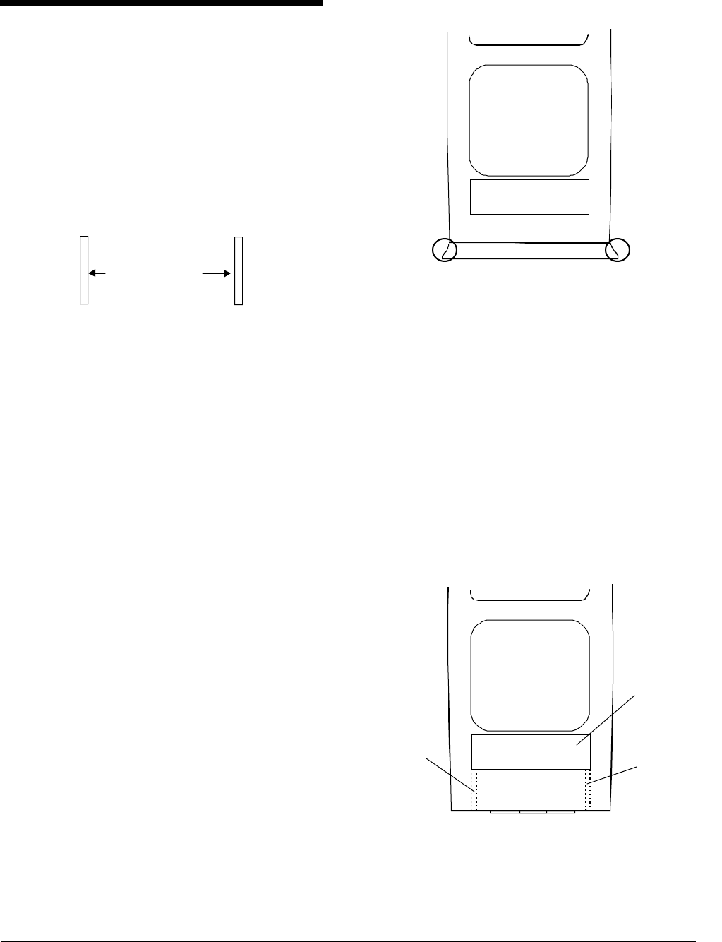
1. Position ADS Pro•Max pedestals at exact
mounting location (Figure 3).
DO NOT space pedestals more than 2.7m (9')
apart.
Figure 3. Pedestal spacing
2. If you need to trench the floor between the
pedestals, do the following:
Using the floor saw and the appropriate blade,
trench the floor from pedestal to pedestal.
Trench depth is 1.5cm (3/4"); trench width is
.5cm (1/4"). Trench depth allows for .5cm (1/4")
of floor compound above the cable.
Make sure that the trench extends under the
pedestal location so cables can directly enter
the pedestal from underneath.
3. Route cables from pedestal to pack or pack
to pedestal.
A four conductor Tx/Rx cable (0650-2219-01)
and a nine conductor Com cable (0650-2220-
01) attaches to each pedestal.
4. Prepare for cable entry (Figure 4).
Cables can enter the pedestal via a trench,
surface Wiremold or buried conduit. Cut the
shroud to fit the Wiremold if necessary.
Figure 4. Cable entry points (circled)
5. Remove capacitor board cover and route
Tx/Rx and Com cables up through base of
pedestal (Figure 5).
a. Remove screws holding capacitor board
cover in place and remove cover.
b. Push Tx/Rx cable up through channel in
base on left side of capacitor board.
c. Push Com cable up through channel in
base on right side of capacitor board.
Figure 5. Cable routing in base
2.78m (9') max.
Ped. 1 Ped. 2
Cap board
cover
Com cable
channel
Tx/Rx cable
channel
6 INSTALLATION GUIDE ADS PRO•MAX PEDESTAL
S
8000-2693-03, REV.
A
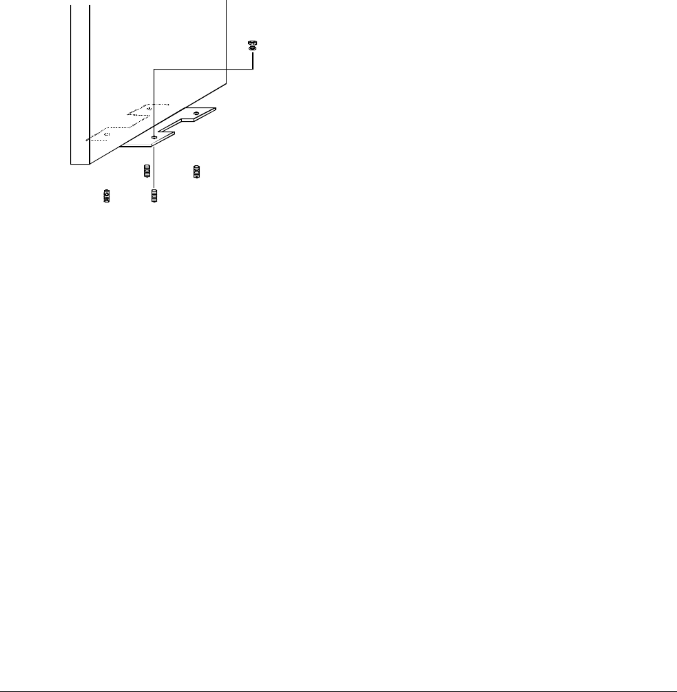
6. Bolt the pedestal to the floor (Figure 6).
a. Using the base holes as a template, mark
locations for four mounting holes.
b. Drill 9.6mm (3/8") holes to a depth of 7cm
(2.75") for each anchor. Tap an anchor into
each hole, leaving 2.5cm (1") of exposed
threads.
c. Place the mounting holes over the four
protruding anchors. Secure the base to the
floor using anchor hardware provided.
Figure 6. Bolting down the pedestal
7. For each pedestal, connect the Tx/Rx (4
conductor) and Com (9 conductor) cables to
the capacitor board. Refer to Figure 2 and
Figure 7.
a. Using a small screwdriver, attach the
TX/Rx cable to connector 2109-0254-04
according to the following table:
Pin 1 - Black
Pin 2 - Red
Pin 3 - Green
Pin 4 - White
Pin 5 - Shield
b. Insert connector 2109-0254-04 into
pluggable terminal block P1 on the
capacitor board.
c. Using a small screwdriver, attach the Com
cable to connector 2109-0510-10 following
the color-coded label:
Pin 1 - Black
Pin 2 - Brown
Pin 3 - Red
Pin 4 - Orange
Pin 5 - Yellow
Pin 6 - Green
Pin 7 - Blue
Pin 8 - Violet
Pin 9 - Gray
Pin 10 - Shield
d. Insert connector 2109-0510-01 into
pluggable terminal block P6 on the
capacitor board.
8. Connect Tx/Rx cables (4 conductor) to the
power pack (Figure 2).
WARNING: Do NOT hot plug cables. Turn off
the power pack before connecting cables.
a. Install Romex-type connectors or conduit
fittings in knockouts on pack.
b. Route each Tx/Rx cable through knockout.
c. Using a small screwdriver, attach Tx/Rx
cables to connectors 2109-0351-05
according to the following table:
Pin 1 - Black
Pin 2 - Red
Pin 3 - Green
Pin 4 - White
Pin 5 - Shield
d. Insert Tx/Rx cable for pedestal A into
pluggable terminal block Tx/Rx A; insert
transmit cable for pedestal B into pluggable
terminal block Tx/Rx B.
ADS PRO•MAX PEDESTALS
8000-2693-03, Rev. A INSTALLATION GUIDE 7
9. Connect Com cables (9 conductor) to the
power pack.
a. Install Romex-type connectors or conduit
fittings in knockouts on pack.
b. Route each Com cable through knockout.
c. Using a small screwdriver, attach
connectors 2109-0510-10 to each Com
cable following the color-coded label.
Pin 1 - Black
Pin 2 - Brown
Pin 3 - Red
Pin 4 - Orange
Pin 5 - Yellow
Pin 6 - Green
Pin 7 - Blue
Pin 8 - Violet
Pin 9 - Gray
Pin 10 - Shield
d. Insert connectors into pluggable terminal
blocks on the power pack. Connect
pedestal A to Com A; connect pedestal B
to Com B.
CAUTION: Be sure the Tx/Rx and Com
cables for a pedestal are attached to
corresponding connectors. Incorrect
connections will cause incorrect alarm
signaling.
Proceed to Pedestal Tuning on page 8.
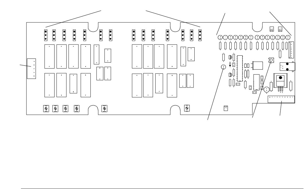
Figure 7. Capacitor board 0301-1532-01
P1 –
Tx/Rx
P6 - Com
Tx Off LED Check
Tuning
button
Tuning jumpers
JW1 – JW14 Tuning jumper LEDs
DS1 – DS14
8 INSTALLATION GUIDE ADS PRO•MAX PEDESTAL
S
8000-2693-03, REV.
A
Pedestal Tuning
The pedestal is shipped with default settings that
are acceptable for most installations. However, the
pedestal may require tuning to adjust for
conditions at the installation site.
The pedestal is tuned by changing jumper settings
on the capacitor board in each pedestal. The
power pack assists tuning by lighting LEDs to
indicate the correct jumper settings.
To tune the pedestal, do the following for each
pedestal:
1. If necessary, turn off the power pack.
2. Access the capacitor board in the pedestal.
Refer to Figure 8.
3. Make sure the jumpers are set to the
defaults.
JW1 - In (1-2)
JW2 - Out (2-3)
JW3 - In (1-2)
JW4 - In (1-2)
JW5 - In (1-2)
JW6 - Out (2-3)
JW7 - Out (2-3)
JW8 - In (1-2)
JW9 - Out (2-3)
JW10 - In (1-2)
JW11 - In (1-2)
JW12 - In (1-2)
JW13 - Out (2-3)
JW14 - Out (2-3)
4. Turn on the power pack.
5. Check the green status LED on the
pedestal.
If the green status LED is ON continuously,
the pedestal is tuned and pedestal
installation is complete.
If the green status LED is blinking, the
pedestal needs tuning. Proceed to step 6.
6. Change the jumpers on the capacitor board
to the settings indicated by the yellow LEDs
on the capacitor board. Refer to Figure 7.
WARNING—RISK OF ELECTRIC
SHOCK!
The green Tx Off LED on the capacitor
board must be ON before changing
jumpers. It indicates there are no high
voltages on the board.
If a yellow jumper LED is on, place the
corresponding jumper in the 1-2 position.
If a yellow jumper LED is off, place the
corresponding jumper in the 2-3 position.
7. Press the Check Tuning button on the
capacitor board and return to step 5.
After repeating steps 5 and 6 several times, the
pedestal should be tuned with the green status
LED on continuously. If not, contact
Sensormatic Customer Service.
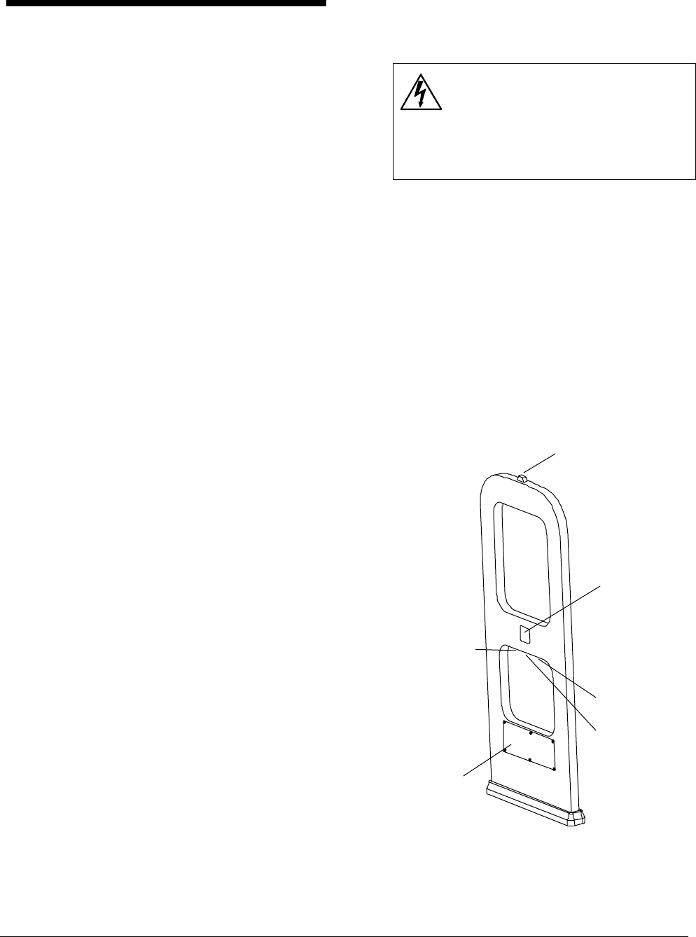
Figure 8. Pedestal features
Alarm light
Speaker
Transmit
inhibit
keyswitch
RS232 port
Status LED:
On – Normal
operation
Blinking –
Tuning required
Off – Power off
Capacitor board
(behind cover)

ADS PRO•MAX PEDESTALS
8000-2693-03, Rev. A INSTALLATION GUIDE 9
Specifications
Electrical
Power Supply (Non-European Power Pack)
Primary Input: ...................100-120Vac or
220-240Vac
@ 50–60Hz
Primary Power Fuse:.........5A, 250V slo-blow
Current Draw: ...................2.0A peak
Input Power: .....................<180W
Transmitter
Outputs:............................2 ports (two antennas,
multiplexed)
Operating Frequency:........58 or 60kHz (±200Hz)
Transmit Burst Duration.....1.6ms
Transmit Current: ..............16A peak
Burst Repetition Rate:
Based on 50Hz ac.............37.5Hz (Normal)
75Hz (Validation)
Based on 60Hz ac.............45Hz (Normal)
90Hz (Validation)
Receiver
Inputs:..............................2 ports (two antennas,
multiplexed)
Center Frequency:.............58 or 60kHz
Receive Coil Resistance:...1.6 ohms (±5%)
Alarm
Alarm Relay Output...........DPDT contacts
Contact Switching Current .1.0A max.
Contact Switching Voltage .28V max.
Lamp/Audio Duration.........1–30 sec.
(1 sec. increments)
Environmental
Ambient Temperature:.......0°C to 50°C (32°F to
122°F)
Relative Humidity:.............0 to 90% non-
condensing
Mechanical
Height ..............................164cm (64 ½”)
Width................................70cm (27 5/8”)
Depth...............................5cm (2")
Weight..............................21kg (46lbs.)

10 INSTALLATION GUIDE ADS PRO•MAX PEDESTAL
S
8000-2693-03, REV.
A
Declarations
Regulatory Compliance (Non-
European Power Pack)
Safety:............................UL 1950
Can/CSA C22.2
No. 950
EMC:..............................47 CFR, Part 15
FCC COMPLIANCE: This equipment has been tested and
found to comply with Part 15 of the FCC Rules. Operation is
subject to the following two conditions: 1) this device may
not cause harmful interference, and 2) this device must accept
any interference received, including interference that may
cause undesired operation.
EQUIPMENT MODIFICATION CAUTION: Equipment
changes or modifications not expressly approved by
Sensormatic Electronics Corporation, the party responsible for
FCC compliance, could void the user’s authority to operate
the equipment and could create a hazardous condition.
Other Declarations
WARRANTY DISCLAIMER: Sensormatic Electronics
Corporation makes no representation or warranty with respect
to the contents hereof and specifically disclaims any implied
warranties of merchantability or fitness for any particular
purpose. Further, Sensormatic Electronics Corporation
reserves the right to revise this publication and make changes
from time to time in the content hereof without obligation of
Sensormatic Electronics Corporation to notify any person of
such revision or changes.
LIMITED RIGHTS NOTICE: For units of the Department
of Defense, all documentation and manuals were developed at
private expense and no part of it was developed using
Government Funds. The restrictions governing the use and
disclosure of technical data marked with this legend are set
forth in the definition of “limited rights” in paragraph (a) (15)
of the clause of DFARS 252.227.7013. Unpublished - rights
reserved under the Copyright Laws of the United States.