Tyco Safety Sensormatic UMADSNE Ultra Max Advanced Digital System User Manual floor antenna install guide
Tyco Safety Products/Sensormatic Ultra Max Advanced Digital System floor antenna install guide
Contents
- 1. Power pack install guide
- 2. pedestal install guide
- 3. floor antenna install guide
- 4. users manual
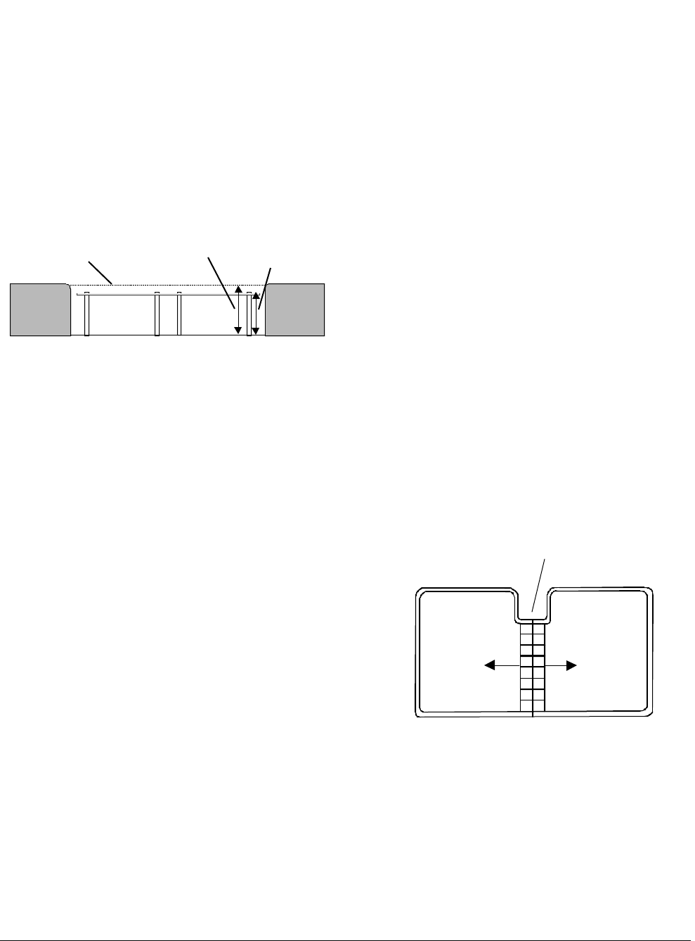
floor antenna install guide
WORLD LEADER IN ELECTRONIC SECURITY Installation Guide
8000-2693-04, Rev. A (19 pages) ULTRA•MAX PRODUCTS 1
1 ADS Floor•Max
Antennas
Contents
About this Guide................................................ 1
Limitation of Warranty........................................ 1
Antenna Overview............................................. 2
Installation Requirements................................... 3
Installing ADS Floor•Max Antennas .................... 7
Connecting Conduit and Cables ....................... 11
Antenna Tuning............................................... 15
Pouring the Concrete....................................... 16
Specifications.................................................. 18
Declarations.................................................... 19
About this Guide
This installation guide explains how to install ADS
Floor•Max antennas. Other related documents
are:
• Planning Guide, 8000-2693-01
• Installation Guide, ADS 216 Power Pack,
8000-2693-02
• Setup and Service Guide, 8000-2693-xx
• Reference Guide, 8000-2693-xx
Note: Because placement of antenna components
depends on architectural and customer require-
ments, your Sensormatic representative will supply
this information separately.
If you need assistance...
Call Sensormatic Customer Support at:
1-800-543-9740
Limitation of Warranty
Any deviations from the materials or procedures
specified herein shall void Sensormatic's warranty
with the owner/buyer. In no event shall Sensor-
matic be liable for loss or damage caused by the
use of materials or procedures that do not meet
Sensormatic's specifications.
Ultra•Max, Floor•Max, Sensormatic, and the Sensormatic
logo are registered trademarks of Sensormatic Electronics
Corporation. Other product names (if any) mentioned herein
may be trademarks or registered trademarks of other
companies.
No part of this guide may be reproduced in any form without
written permission from Sensormatic Electronics Corporation.
© Copyright 2000. All rights reserved.
DOJ 01/00
PRELIMINARY – 01/31/00
2 INSTALLATION GUIDE ADS FLOOR•MAX ANTENNA
S
8000-2693-04, REV.
A
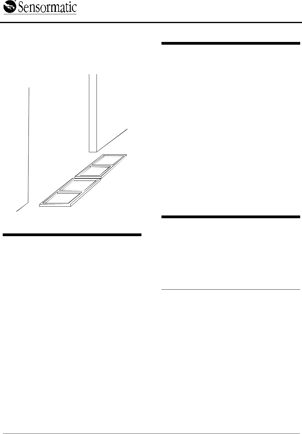
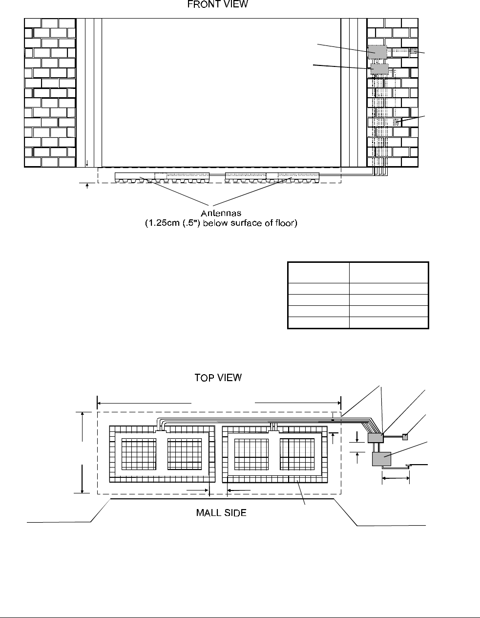
Antenna Overview
ADS Floor•Max antennas, positioned at an exit,
are part of an Ultra•Max security label detector that
deters theft. One or two ADS Floor•Max in-floor
antennas are attached to a power pack through a
capacitor board enclosure.
Figure 1. ADS Floor•Max Detector
Component Part Numbers
ADS Floor•Max 6' System
− 1 ADS Floor•Max Antenna (ZSFLORMX-
ANT)
− ADS Enclosure Assembly (ZPFLORMX-
ENC)
− RS232 Assembly (ZPFLORMX-232)
− ADS Power Pack (ZEADS216)
ADS Floor•Max 12' System
− 2 ADS Floor•Max Antennas (ZSFLORMX-
ANT)
− ADS Enclosure Assembly (ZPFLORMX-
ENC)
− RS232 Assembly (ZPFLORMX-232)
− ADS Power Pack (ZEADS216)
ADS Floor•Max Antenna (ZSFLORMX-ANT)
− Install kit (0351-1696-01)
− Capacitor board (0301-1536-01)
− Antenna (0300-2289-01)
ADS Floor•Max Shield (ZPFLORMX-SH)
− Shield tray - left (0300-9219-01
− Shield tray - right (0300-9219-02)
− Shield tiles (0500-9216-01)
Power
pack
Optional
remote
alarm
In-floor
antennas
Cap board
enclosure
RS232
plate
ADS FLOOR•MAX ANTENNAS
8000-2693-04, Rev. A INSTALLATION GUIDE 3
Installation Requirements
Verifying Equipment and Unpacking
❑ Verify that all equipment has arrived. Make
sure the system configuration is the right one
for the installation site.
❑ Unpack major components in a back room. At
the install site, lay out parts in the order you will
need them. Do not clutter the aisle or cause a
trip hazard.
Note: The capacitor board is in a cardboard
sleeve taped to the bottom of the antenna
shipping box. The PVC leveling legs are inside
one of the cardboard support ribs on the end of
the box.
Installer/Contractor
❑ Shall have electrical work comply with the
latest national electrical code, national fire
code, and all applicable local codes and
ordinances.
❑ Shall coordinate all work with other trades to
avoid interference.
❑ Shall verify existing site conditions and
coordinate with the owner’s representative and
appropriate utilities as required.
❑ Shall obtain copies of all related plans,
specifications, shop drawings and addenda to
schedule and coordinate related work.
❑ Shall thoroughly review the project to ensure
that all work meets or exceeds the above
requirements. Any alleged discrepancies shall
be brought to the attention of Sensormatic
Electronics.
Chemical Interaction
!WARNING!
Do not install this product in hazardous
areas where highly combustible or
explosive products are stored or used.
Antenna Placement and Cabling
❑ Whenever possible, keep the antennas at least
2.4m (8') away from noise sources such as
computer monitors, TV’s, switching power
supplies, and neon displays.
❑ Maximum cable distance from the antennas to
the capacitor board enclosure is 12.2m (40').
DO NOT splice antenna cables.
❑ Maximum cable distance from the power pack
to the cap board enclosure is 2m (7').
!WARNING!
DO NOT compromise the structural
integrity of the floor by cutting or removing
rebar. Contractors must obtain approval for
all proposed structural changes. All
structural changes must meet national and
local requirements.
CAUTION: To avoid adding significant time and
cost to the in-floor installation, check detector per-
formance and label detection height at the exact
installation site. Do this BEFORE cutting the floor
and again BEFORE pouring the concrete.
❏ Locate panels inside the facility and as close to
exit doors as possible.
❏ To provide 1.8m (6') of coverage width per
panel, space panels no more than 25-30cm
(10-12") apart. Spacing of 25cm (10") is
recommended.
❏ For On Grade installations, the panels must be
between 3cm (1.25") and 5cm (2") below the
surface of the finished floor.
❏ For Off Grade installation, the panels must be
1.25cm (.5") below the surface of the finished
floor.
❏ For On Grade installations, no metal such as
rebar or wire mesh should be located under or
adjacent to the antenna. If metal is required, it
must be spaced greater than 21cm (8") from
the bottom and 31cm (12") in all other
directions from the antenna.
❏ For conduit runs, use 3/4-inch Electrical Metal
Tubing (EMT) or rigid conduit (not plastic) with
the maximum run not to exceed 10.5m (35') to
allow adequate cable length for system
connections. Some local codes require rigid
conduit instead of EMT for concrete burial.
Some local codes require steel hardware in
concrete to be coated by tape or paint before
burial.
❏ Use two separate conduit runs for each
antenna. Conduit run must be a minimum of
20cm (8") from the antennas. Conduit cannot
cross above or below the antenna. It must be
routed around the perimeter.

4 INSTALLATION GUIDE ADS FLOOR•MAX ANTENNA
S
8000-2693-04, REV.
A
❏ All conduit fittings must be rain/concrete tight. A
3/4-inch EMT fitting is supplied with the
antenna. A rigid 3/4-inch rain/concrete tight
fitting may be substituted. Wrap threads with
four turns of Teflon pipe tape.
❏ Minimize underground conduit couplings to
prevent moisture intrusion.
❏ High strength, non-metallic, non-shrink
mortar/concrete with a compressive strength of
5000 psi is required.(For example, FX-228
mortar mix and FX-752 bonding agent by Fox
Industries)
❏ Mortar cure time depends on the mix and
temperature of the mortar ingredients.
❏ Avoid walking on antenna cables during
installation.
❏ Heavy forklifts can pass over the mortar after
24 hours, provided the mortar is protected by
3/4-inch steel plates.
❑ Have on hand tools and equipment necessary
to place the mortar once it is mixed.
Enclosure
❏ Mount the cap board enclosure as close to the
power pack as possible. Maximum distance
from the power pack to the enclosure is 2m (7').
❑ Install a heater in enclosures in sub-freezing
environments.
❑ If conduit is not used, use Romex connectors
wherever cables enter the power pack and
capacitor board enclosure.
Tools and Equipment Required
For all ADS Floor•Max system installations:
• 6 mil (minimum) plastic sheeting (to protect
nearby items from dust)
• Chalk or red permanent marker
• Floor saw
• PVC pipe cutter or hacksaw
• Hammer drill with 6.5mm (1/4") and 9.6mm
(3/8") masonry drill bits
• Power drill with 1.6mm (1/16"), 6.5mm (1/4"),
and 9.6mm (3/8") drill bits
• Hammer
• Phillips and slotted screwdrivers
• 14-16 AWG and 16-22 AWG wire strippers
• Ratchet and socket set
• Vacuum and broom
• Wet vacuum
• Level
• Electrical tape
• Teflon pipe tape
• Caution tape
• Duct tape
ADS FLOOR•MAX ANTENNAS
8000-2693-04, Rev. A INSTALLATION GUIDE 5
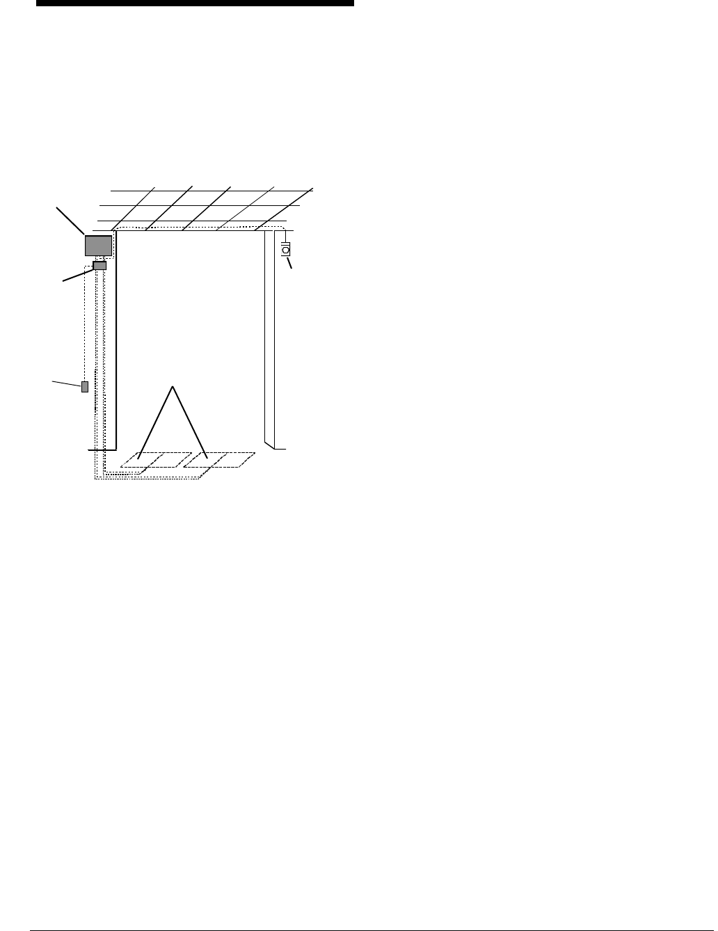
Figure 2. “On Grade” installation diagram
Power pack
Remote
alarm
7.5m (25') max
Conduit run
10.5m (35') max
No metal rebar or wire mesh
within 21cm (8") of bottom and
31cm (12") of sides of antenna
25cm (10")
Power
pack
Remote
alarm
Cap board
enclosure
Cap board
enclosure
[a]
[b]
[a]
RS232
plate
RS232
plate
Antennas
(3cm (1.25") min to 5cm (2") max below surface of floor)
3.98m (13' 1")
1.29m
(4' 3")
[a] - 20cm (8") min
[b] - 2m (7') max
[c] - 25cm (10")
[c]
No. of
antennas Length of
excavation
1 2.18m (7' 2")
2 3.98m (13' 1")
3 5.80m (19' 0")
4 7.61m (24' 11")
6 INSTALLATION GUIDE ADS FLOOR•MAX ANTENNA
S
8000-2693-04, REV.
A
Figure 3. “Off Grade” installation diagram
7.5m (25') max
Conduit run
10.5m (35') max
1.14m
(3' 9")
3.93m (12' 11")
Power
pack
Remote
alarm
Cap board
enclosure
[a] - 20cm (8") min
[b] - 2m (7') max
[c] - 25cm (10")
[a]
[b]
RS232
plate
Power pack
Remote
alarm
5cm (2")
Cap board
enclosure
RS232
plate
[c]
Shield
tiles
No. of
antennas Length of
excavation
1 1.91m (6' 3")
2 3.93m (12' 11")
3 5.95m (19' 6")
4 7.96m (26' 2")
ADS FLOOR•MAX ANTENNAS
8000-2693-04, Rev. A INSTALLATION GUIDE 7
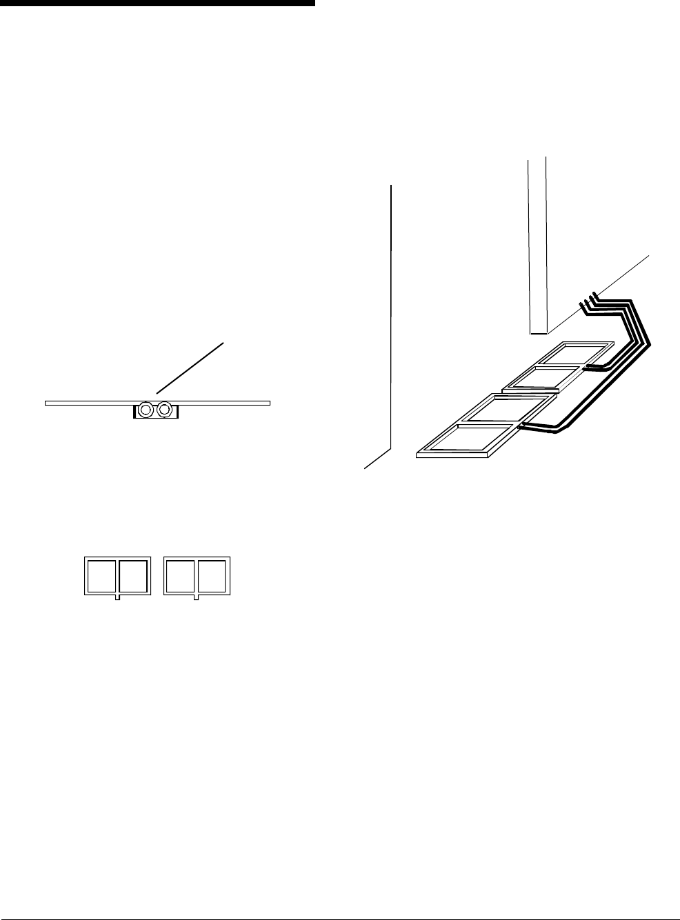
Installing ADS Floor•Max
Antennas
1. Lay out ADS Floor•Max antennas as shown
for proper antenna phasing (Figure 4).
Locate panels inside the facility and as close to
exit doors as possible.
DO NOT space antennas more than 25-30cm
(10-12") apart. Spacing of 25cm (10") is
recommended.
The flat side of the cable entry neck must face
up.
Figure 4. ADS Floor•Max antenna
orientation for proper phasing
CAUTION: To avoid adding significant time and
cost to the in-floor installation, check detector per-
formance and label detection height at the exact
installation site. Do this BEFORE cutting the floor
and again BEFORE pouring the concrete.
2. Determine the placement of conduit runs
(Figure 5).
Two separate conduit runs are required for
each antenna.
Conduit must terminate at the capacitor
board enclosure for proper grounding.
Figure 5. Antenna with conduit attached
Front view of antenna
showing flat side of
neck facing up.
Ant. 1 Ant. 2
Top view
8 INSTALLATION GUIDE ADS FLOOR•MAX ANTENNA
S
8000-2693-04, REV.
A
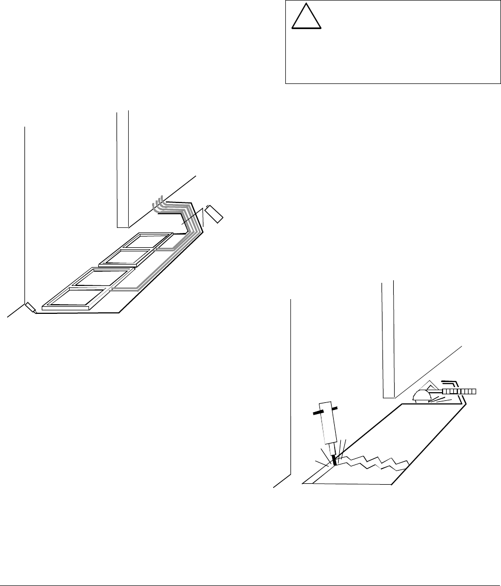
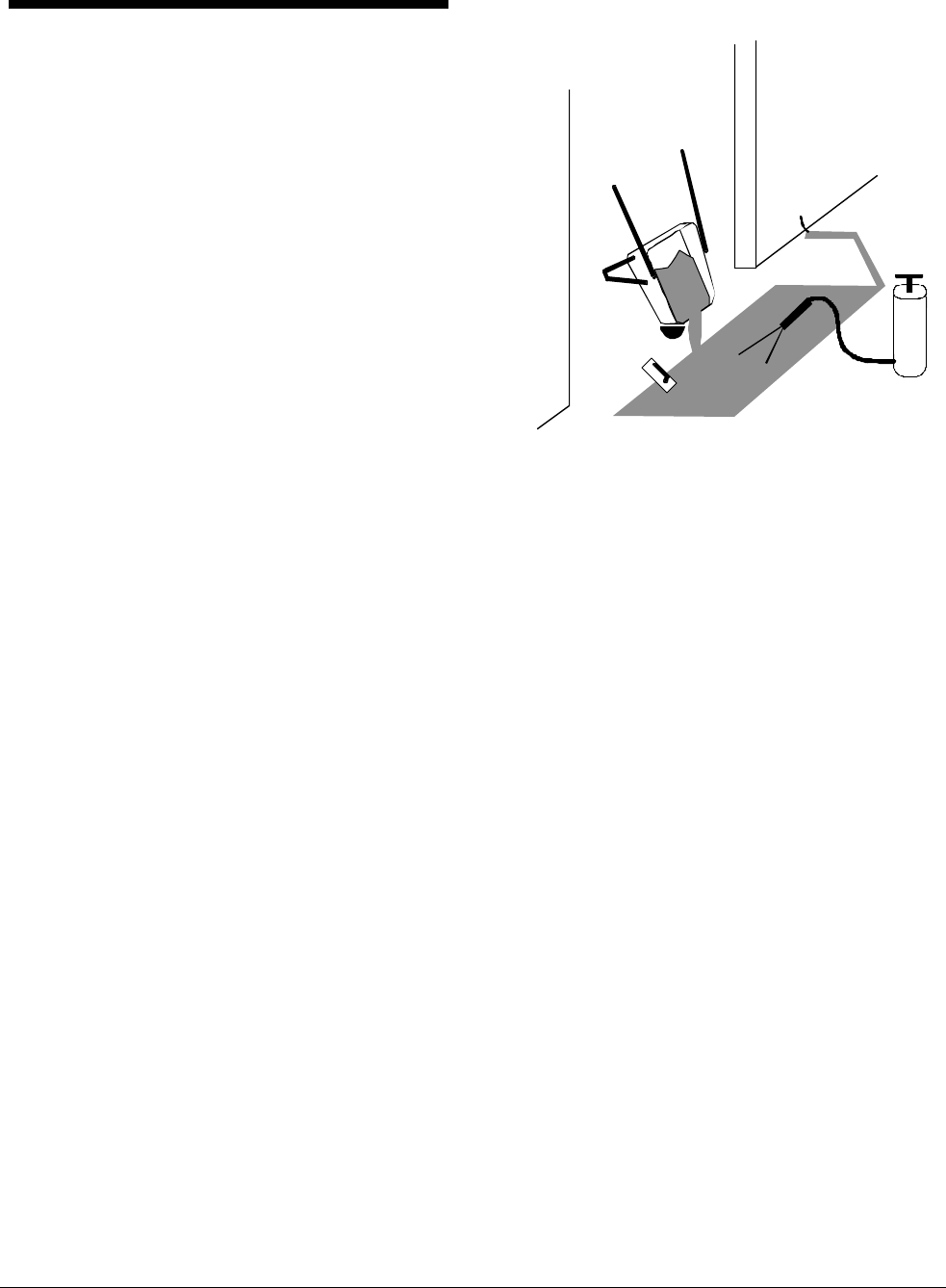
3. Mark excavation location on floor. Refer to
Figure 2 or Figure 3 for recommended
length and width of excavation.
a. With each antenna in place, use a chalk
line or wide tip red permanent marker to
trace an outline around the outside of the
antenna and conduit. Also trace the conduit
route from the antenna back to the cap
board enclosure (Figure 6).
b. Remove the antennas.
c. Spray all floor markings with clear lacquer
to prevent erasure during the floor
excavation process (next).
Figure 6. Marking the excavation location
4. Excavate the floor (Figure 7).
a. Using a concrete saw, cut along the
outline.
For “On Grade” installation, cut down to grade.
For “Off Grade” installation, cut to a minimum
depth of 5cm (2").
!WARNING!
DO NOT compromise the structural
integrity of the floor by cutting or
removing rebar. Contractors must obtain
approval for all proposed structural
changes. All structural changes must
meet national and local requirements.
b. Using the specified chipping hammer,
break up the floor and remove the
concrete.
Note: Fiberglass reinforced plastic (FRP) rebar
can be used in the excavation to prevent
cracking and settling. Drill 9/16" diameter holes
and dowel the rebar into the sides of the
excavation. Dowels should be installed in the
holes using concrete adhesive. Refer to
Figure 8.
c. Remove all debris from the channels using
water and a wet vacuum.
Figure 7. Excavating the floor
ADS FLOOR•MAX ANTENNAS
8000-2693-04, Rev. A INSTALLATION GUIDE 9
Figure 8. FRP rebar installation
For “Off Grade” installations, proceed to “Off
Grade” Installation on page 10
“On Grade” Installation
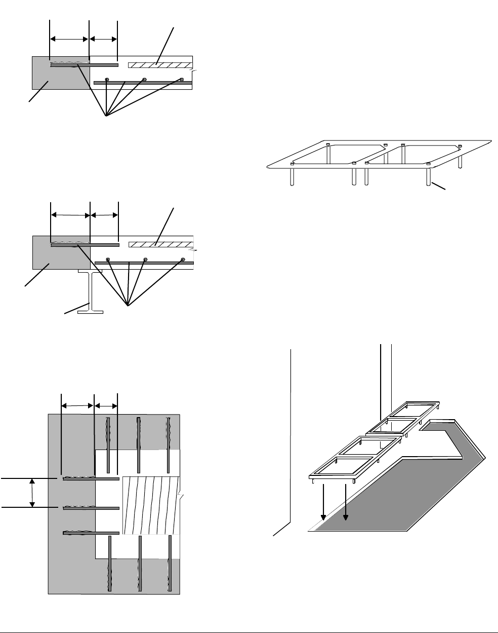
5. Assemble the antenna supports, if needed.
(Figure 9).
Insert eight support rods into the antenna
support holes in the antenna.
Figure 9. Antenna with support rods
6. Level the ground underneath the antenna
and place the antenna with support rods
into the pit.
The antenna must be a minimum of 3cm (1.25")
and a maximum of 5cm (2") below the surface
of the finished floor.
Figure 10. Placing supports and assembly
31cm
(12")
min
31cm
(12")
min
Existing slab
FRP reinforcing bars
spaced at 31cm (12") on center
FRP reinforcing bars
spaced at 31cm (12") on center
Floor•Max
antenna
Floor•Max
antenna
25cm
(10")
25cm
(10")
“On Grade” installation
“Off Grade” installation
Existing steel beam
Existing deck
Top view
25cm
(10")
31cm
(12")
min
31cm (12")
on center
Support
rod
10 INSTALLATION GUIDE ADS FLOOR•MAX ANTENNA
S
8000-2693-04, REV.
A
7. If necessary, cut the antenna support rods
so that the antenna is level (Figure 11).
a. For each support rod, measure the depth of
the excavation from the surface of the
finished floor.
b. Cut the support rod to the length of the
depth of the excavation minus the depth of
the antenna (3cm (1.25") to 5cm (2")).
Figure 11. Cutting the support rods
Proceed to “Connecting Conduit and Cables”
on page 11.
“Off Grade” Installation
5. Smooth the surface in the bottom of the pit.
Remove any peaks or valleys in the bottom of
the pit so that the tray will be supported firmly.
6. Assemble the tray.
Place the two halves of the tray together and
secure with duct tape on the outside of the
bottom of the tray.
7. Place the tray in the pit.
Orient the tray so that the cutout is on the side
where the conduit attaches to the antenna.
8. Place tiles on tray.
Completely cover the bottom of the tray with
closely packed tiles. Begin placing tiles along
the center line of the tray. Work from the center
to the outside of the tray. Refer to Figure 12.
9. Place the antenna on tiles.
Place the antenna on the tiles so that the
conduit housing is over the cutout in the tray
and the antenna is centered over the tiles.
Figure 12. Placing tiles on tray
Depth of
excavation
Length of rod =
depth of excavation
minus depth of
antenna
Finished floor
Center line
ADS FLOOR•MAX ANTENNAS
8000-2693-04, Rev. A INSTALLATION GUIDE 11
Connecting Conduit and
Cables
1. Attach conduit to the antenna and pull the
antenna cables (Figure 5).
a. Lay out 3/4-inch EMT or rigid conduit from
the antenna to the cap board enclosure.
Two separate conduit runs are required
for each antenna.
Conduit must terminate at the capacitor
board enclosure for proper grounding.
b. For DIY installations, lay out conduit from
the power pack to the capacitor board
enclosure. Maximum conduit run from the
power pack to the enclosure is 2m (7').
c. Pull the antenna cables from the antenna
to the enclosure.
d. Label the cables indicating the location of
the attached in-floor panel for future
servicing.
e. Attach all conduit and tighten all conduit
connectors. Use only rain/concrete tight
EMT or rigid connectors.
f. Ground the conduit to an earth ground by a
code-approved method such as a clamp.
WARNING—RISK OF ELECTRIC
SHOCK!
Failure to ground correctly could cause
shock risk.
2. Connect Tx/Rx cables (5 conductor) to the
power pack (Figure 15).
WARNING: Do NOT hot plug cables. Turn off
the power pack before connecting cables.
a. Install Romex-type connectors or conduit
fittings in knockouts on pack.
b. Route each Tx/Rx cable through knockout.
c. Using a small screwdriver, attach Tx/Rx
cables to connectors 2109-0351-05
according to the following table:
Pin 1 - Black
Pin 2 - Red
Pin 3 - Green
Pin 4 - White
Pin 5 - Shield
d. Insert Tx/Rx cable for panel A into
pluggable terminal block Tx/Rx A; insert
transmit cable for panel B into pluggable
terminal block Tx/Rx B.
3. Connect Com cables (10 conductor) to the
power pack.
a. Route each Com cable through knockout.
b. Using a small screwdriver, attach
connectors 2109-0510-10 to each Com
cable following the color-coded label.
Pin 1 - Black
Pin 2 - Brown
Pin 3 - Red
Pin 4 - Orange
Pin 5 - Yellow
Pin 6 - Green
Pin 7 - Blue
Pin 8 - Violet
Pin 9 - Gray
Pin 10 - Shield
c. Insert connectors into pluggable terminal
blocks on the power pack. Connect panel A
to Com A; connect panel B to Com B.
CAUTION: Be sure the Tx/Rx and Com
cables for a panel are attached to
corresponding connectors. Incorrect
connections will cause incorrect alarm
signaling.
4. Determine whether the capacitor board
enclosure will be mounted vertically or
horizontally. Refer to Figure 13. Identify
correct knockout locations for antenna
conduit and connection to power pack.
5. Mount cap board enclosure close to power
pack.
Mount with 3/16" Tapcons® on masonry wall or
#10 self-tapping screws with anchors on
drywall. Mounting hardware is not supplied.
6. Mount capacitor boards in enclosure and
pull cables from pack to enclosure.
7. Mount RS232 plate and pull cable from
enclosure to RS232 plate.
The RS232 plate can be mounted on the side
of the cap board enclosure or remotely using a
standard duplex junction box.
12 INSTALLATION GUIDE ADS FLOOR•MAX ANTENNA
S
8000-2693-04, REV.
A
8. Connect RS232 cable to cap board and
RS232 plate.
a. Connect the 8 conductor cable to P3 - cap
board A and the 2 conductor cable to P4 -
cap board B.
b. Cut cable to length leaving sufficient slack
to connect to RS232 plate.
c. Remove 6" to 8" of the outer jacket. Strip
all conductors 1/8". Insert shrink tubing
over drain wire to prevent shorting of
printed circuit board.
d. Connect to connector 2109-0510-10 in the
RS232 plate following the color-coded
label.
Pin 1 - Black
Pin 2 - Brown
Pin 3 - Red
Pin 4 - Orange
Pin 5 - Yellow
Pin 6 - Green
Pin 7 - Blue
Pin 8 - Violet
Pin 9 - Gray
Pin 10 - Shield
Pin 1 is on the right end of the connector as
you look at the rear of the RS232 plate.
9. Connect power pack com cable to cap
board.
a. Route cable through knockout.
b. Using a small screwdriver, attach
connectors 2109-0510-10 to each Com
cable following the color-coded label.
Pin 1 - Black
Pin 2 - Brown
Pin 3 - Red
Pin 4 - Orange
Pin 5 - Yellow
Pin 6 Green
Pin 7 Blue
Pin 8 Violet
Pin 9 Gray
Pin 10 Shield
c. Insert connectors into pluggable terminal
blocks on cap board. Connect panel A to
P2 on cap board A; connect panel B to P2
on cap board B.
10. Connect antenna coil cables to cap board.
Use a separate conduit and knockout for
each coil start and finish pair (two per
antenna). Refer to Figure 15.
a. Route each antenna cable pair through
knockout and secure away from cap board
with cable clamps located on partition and
sidewall.
b. Attach panel A to TB1-TB4 on cap board A;
attach panel B to TB1-TB4 on cap board B.
Attach using the following table:
TB1 - Bottom coil start (black)
TB2 - Bottom coil finish (white)
TB3 - Top coil start (black)
TB4 - Top coil finish (white)
!CAUTION!
For proper operation and reliability,
connect the large diameter, white, coil-
finish cables to TB2 and TB4 only.
c. Attach ground wires from enclosure
chassis to TB5 on cap boards A and B.
11. Connect power pack Tx/Rx cable to cap
board.
a. Route each Tx/Rx cable through knockout
and secure away from cap board with cable
clamps located on partition and sidewall.
b. Using a small screwdriver, attach Tx/Rx
cables to connectors 2109-0254-04
according to the following table:
Pin 1 - Black
Pin 2 - Red
Pin 3 - Green
Pin 4 - White
Pin 5 Shield
c. Insert Tx/Rx cable for panel A into
pluggable terminal block P1 on cap board
A; insert Tx/Rx cable for panel B into
pluggable terminal block P1 on cap board
B.
Proceed to “Antenna Tuning” on page 15.
ADS FLOOR•MAX ANTENNAS
8000-2693-04, Rev. A INSTALLATION GUIDE 13
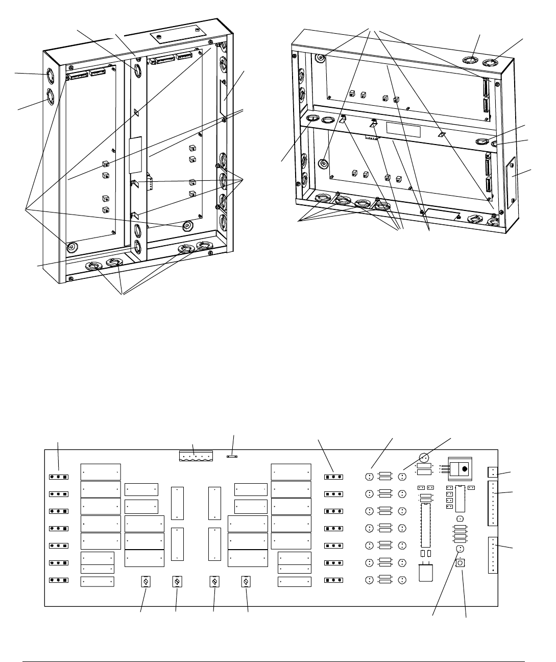
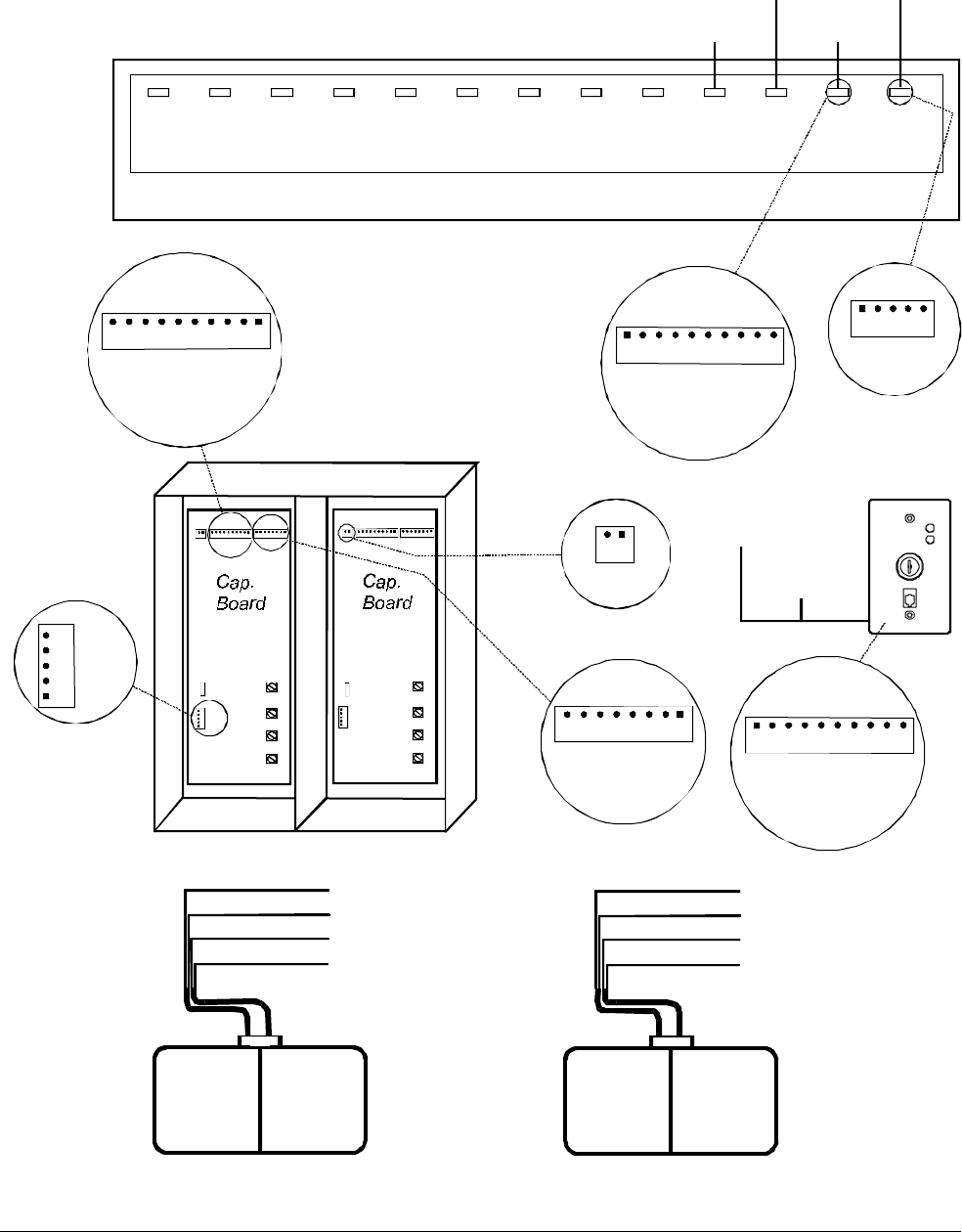
Figure 13. Cap board enclosure
Figure 14. Capacitor board 0301-1536-01
A - Mounting holes
B - Power pack Tx/Rx cable entry
C - Power pack Com cable entry
D - Antenna coil cable entry
E - RS232 plate mounting location
F - Power pack Tx/Rx and Com cable
entry to other compartment
G - Antenna Tx/Rx cable entry to other
compartment
H - RS232 cable entry to other
compartment
I - Cable supports
J - Ground wire (connect to TB5)
V
ertically mounted Horizontally mounted
A
A
B
B
C
C
D
D
E
E
F
F
G
G
H
H
Tuning jumpers
JW1 – JW7
Tuning jumpers Tuning jumper LEDS
JW8 – JW14 DS1 – DS7 DS8 – DS14
P1 - TB5
Tx/Rx
P4
P2 –
Com
P3
Tx Off Check
LED Tuning button
TB1 TB2 TB4 TB3
Bottom Bottom Top Top
Start Finish Finish Start
I
IJ
J
14 INSTALLATION GUIDE ADS FLOOR•MAX ANTENNA
S
8000-2693-04, REV.
A
Figure 15. Wiring diagram
AFloor•
Max
TB1
(
Ca
p
. Board A
)
Bottom Coil Start
B
A
Cap Box RS232
Plate
P3
(Cap. Board A)
P1
P2
TB1
TB2
TB4
TB3
P4 P3
B
P1
P2
TB1
TB2
TB4
TB3
P4 P3
P1
P2
P3
P4
P1
(
Ca
p
. Board A
)
P2
(
Ca
p
. Board A
)
P1
(
Ca
p
. Board B
)
P2
(
Ca
p
. Board B
)
P4
Tx/Rx
Ped. A
P6
Com
Ped. A
P5
Tx/Rx
Ped. B
P7
Com
Ped. B
P13
Relay
A-B
P11
Ferrite
P12
Option
3
P18
Option
2
P17
Option
1
P9
Noise
Coil A
P10
Noise
Coil B
P14
RS485
P8
ADS
Alarm
ADS Power Pack
SHLD
WHT
GRN
RED
BLK
BLK
RED
GRN
WHT
SHLD
Tx/Rx
1 2 3 4 5
Com
1 2 3 4 5 6 7 8 9 10
BLK
BRN
RED
ORG
YEL
GRN
BLU
VIO
GRY
SHLD
10 9 8 7 6 5 4 3 2 1
SHLD
GRY
VIO
BLU
GRN
YEL
ORG
RED
BRN
BLK
2 1
8 7 6 5 4 3 2 1
P4
(Cap. Board B)
TB2 (Cap. Board A)
TB3 (Cap. Board A)
TB4 (Cap. Board A)
Bottom Coil Finish
Top Coil Start
Top Coil Finish
TB1 (Cap. Board B)
Bottom Coil Start
TB2 (Cap. Board B)
TB3 (Cap. Board B)
TB4 (Cap. Board B)
Bottom Coil Finish
Top Coil Start
Top Coil Finish
Floor•
Max
1 2 3 4 5
TB5 TB5
VIO
BLU
GRN
YEL
ORG
RED
BRN
BLK
SHLD
GRY
2109-0510-10
1 2 3 4 5 6 7 8 9 10
BLK
BRN
RED
ORG
YEL
GRN
BLU
VIO
GRY
SHLD

ADS FLOOR•MAX ANTENNAS
8000-2693-04, Rev. A INSTALLATION GUIDE 15
Antenna Tuning
The antenna is shipped with default settings that
are acceptable for most installations. However, the
antenna may require tuning to adjust for conditions
at the installation site.
The antenna is tuned by changing jumper settings
on the capacitor boards in the enclosure. The
power pack assists tuning by lighting LEDs to
indicate the correct jumper settings.
To tune the antenna, do the following for each
antenna:
1. If necessary, turn off the power pack.
2. Access the capacitor board in the
enclosure.
3. Make sure the jumpers are set to the
defaults.
JW1 -
JW2 -
JW3 -
JW4 -
JW5 -
JW6 -
JW7 -
JW8 -
JW9 -
JW10 -
JW11 -
JW12 -
JW13 -
JW14 -
4. Turn on the power pack.
5. Check the green status LED on the RS232
plate.
If the green status LED is ON continuously,
the antenna is tuned.
If the green status LED is blinking, the
antenna needs tuning. Proceed to step 6.
6. Change the jumpers on the capacitor board
to the settings indicated by the yellow LEDs
on the capacitor board. Refer to Figure 14.
WARNING—RISK OF ELECTRIC
SHOCK!
The green Tx Off LED on the capacitor
board must be ON before changing
jumpers. It indicates there are no high
voltages on the board.
If a yellow jumper LED is on, place the
corresponding jumper in the 1-2 position.
If a yellow jumper LED is off, place the
corresponding jumper in the 2-3 position.
7. Press the Check Tuning button on the
capacitor board and return to step 5.
After repeating steps 5 and 6 several times, the
antenna should be tuned with the green status
LED on continuously. If not, contact
Sensormatic Customer Service.
16 INSTALLATION GUIDE ADS FLOOR•MAX ANTENNA
S
8000-2693-04, REV.
A
Pouring the Concrete
CAUTION: To avoid adding significant time and
cost to the in-floor installation, check detector per-
formance and label detection height at the exact
installation site. Do this BEFORE cutting the floor
and again BEFORE pouring the concrete.
1. Prepare the high-strength mortar mix. FX-
228 by Fox Industries is recommended but
not required.
Fox products may be replaced by other mortar
materials as long as they have a compressive
strength of 5000 psi and contain no ferrous
metal. For product specifications, call Technical
Support.
CAUTION: Work time is greatly reduced at
temperatures above 80°F. Complete mortar
placement within the time specified.
2. Rough up the surface and work mortar into
the sawed face of the concrete to promote
bonding and hand shovel mortar around all
support rods before filling the rest of the
pit.
CAUTION: Bottom of antennas must be 100%
supported by mortar—NO VOIDS! Do not lift
antenna assemblies once they have been
placed in the mortar.
3. Completely fill the pit with additional
mortar. Apply the final layer by troweling it
into place (Figure 16).
CAUTION: Use only a small amount of water
when troweling the final top surface to avoid
potential shrinkage cracks. Do not over trowel -
doing so will entrap air or leave blisters in the
mortar.
Figure 16. Adding the final layer
ADS FLOOR•MAX ANTENNAS
8000-2693-04, Rev. A INSTALLATION GUIDE 17
4. Using a garden sprayer, thoroughly coat the
surface of the concrete with curing
compound (refer back to Figure 16).
Wait five minutes for the compound to set.
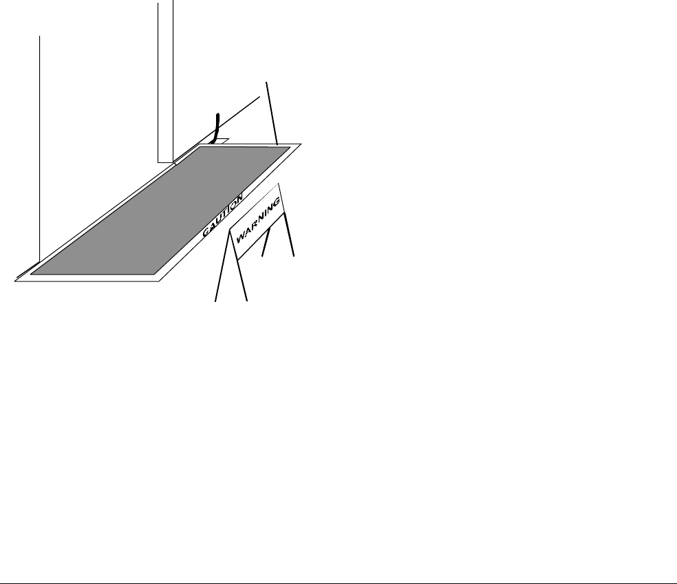
5. Protect the installation for at least 72 hours.
After the initial set, cover mortar with 1.3cm
(1/2") plywood in retail installations and 2cm
(3/4") steel plates in DIY installations.
NOTE: Place signs and caution tape around
the installation to warn of potential trip hazards.
After 24 hours—The wood protected
installation can be opened to pedestrian traffic.
After 72 hours—Remove the steel plate and
plastic sheeting. The floor is now ready for the
desired floor covering (tile, carpet, wood, etc.).
Figure 17. Protecting the installation
STOP!
Wait at least 24 hours before
allowing forklift traffic over the
steel plates.
Wait 72 hours before removing
the plates.
Use caution tape
on edges of
wood or steel trip
hazard

18 INSTALLATION GUIDE ADS FLOOR•MAX ANTENNA
S
8000-2693-04, REV.
A
Specifications
Electrical
Power Supply (Non-European Power Pack)
Primary Input: ...................100-120Vac or
220-240Vac
@ 50–60Hz
Primary Power Fuse:.........5A, 250V slo-blow
Current Draw: ...................2.0A peak
Input Power: .....................<180W
Transmitter
Outputs:............................2 ports (two antennas,
multiplexed)
Operating Frequency:........58 or 60kHz (±200Hz)
Transmit Burst Duration.....1.6ms
Transmit Current: ..............16A peak
Burst Repetition Rate:
Based on 50Hz ac.............37.5Hz (Normal)
75Hz (Validation)
Based on 60Hz ac.............45Hz (Normal)
90Hz (Validation)
Receiver
Inputs:..............................2 ports (two antennas,
multiplexed)
Center Frequency:.............58 or 60kHz
Receive Coil Resistance: ...1.6 ohms (±5%)
Alarm
Alarm Relay Output...........DPDT contacts
Contact Switching Current .1.0A max.
Contact Switching Voltage .28V max.
Lamp/Audio Duration.........1–30 sec.
(1 sec. increments)
Environmental
Ambient Temperature:.......0°C to 50°C
(32°F to 122°F)
Relative Humidity:.............0 to 90%
non-condensing
Mechanical
ADS Floor•Max Panel
Length..............................156cm (61 ¼")
Width................................67cm (26 ½")
Depth...............................2cm (.9")
Weight..............................kg (lbs.)
Antenna Shield
Length..............................180cm (71")
Width................................91cm (36")
Depth...............................3cm (1.3")
Weight..............................kg (lbs.)
Capacitor Board Enclosure
Length..............................47.5cm (18.7")
Width................................37.8cm (14.9")
Depth...............................8.5cm (3.3")
Weight..............................kg (lbs.)
RS232 Plate
Height ..............................11.5cm (4.5")
Width................................7cm (2.7")
Depth...............................1.7cm (.7")
Weight..............................kg (lbs.)

ADS FLOOR•MAX ANTENNAS
8000-2693-04, Rev. A INSTALLATION GUIDE 19
Declarations
Regulatory Compliance (Non-
European Power Pack)
Safety:............................UL 1950
Can/CSA C22.2
No. 950
EMC:..............................47 CFR, Part 15
FCC COMPLIANCE: This equipment complies with Part
15 of the FCC rules for intentional radiators and Class A
digital devices when installed and used in accordance with the
instruction manual. Following these rules provides reasonable
protection against harmful interference from equipment
operated in a commercial area. This equipment should not be
installed in a residential area as it can radiate radio frequency
energy that could interfere with radio communications, a
situation the user would have to fix at their own expense.
EQUIPMENT MODIFICATION CAUTION: Equipment
changes or modifications not expressly approved by
Sensormatic Electronics Corporation, the party responsible for
FCC compliance, could void the user's authority to operate the
equipment and could create a hazardous condition.
Other Declarations
WARRANTY DISCLAIMER: Sensormatic Electronics
Corporation makes no representation or warranty with respect
to the contents hereof and specifically disclaims any implied
warranties of merchantability or fitness for any particular
purpose. Further, Sensormatic Electronics Corporation
reserves the right to revise this publication and make changes
from time to time in the content hereof without obligation of
Sensormatic Electronics Corporation to notify any person of
such revision or changes.
LIMITED RIGHTS NOTICE: For units of the Department
of Defense, all documentation and manuals were developed at
private expense and no part of it was developed using
Government Funds. The restrictions governing the use and
disclosure of technical data marked with this legend are set
forth in the definition of "limited rights" in paragraph (a) (15)
of the clause of DFARS 252.227.7013. Unpublished - rights
reserved under the Copyright Laws of the United States.