UBS Axcera 840A 10,000-watt UHF solid state television transmitter User Manual Chapter 2
UBS-Axcera 10,000-watt UHF solid state television transmitter Chapter 2
Contents
Chapter 2
10-kW UHF Transmitter with Chapter 2, System Description
Feedforward Driver
840A, Rev. 0 2-1
Chapter 2
System Description
The 840A (1064941) is a complete 10-
kW UHF internally diplexed television
transmitter that operates at a nominal
visual output power of 10,000 watts peak
sync visual and an average aural output
power of 1000 watts with a 10 dB
aural/visual ratio.
2.1 System Overview
The 840A is made up of three cabinet
assemblies: the (A1) dual 250-watt
driver/amplifier assembly (1064946);
(A2) the 10-kW amplifier assembly
(1299-1100); and (A3) the high-voltage
power supply assembly, 208/240 VAC
(1068022).
2.1.1 (A1) Dual 250-Watt
Exciter/Amplifier Assembly
(1064946; Appendix A)
The dual 250-watt driver/amplifier
assembly is made up of the assemblies
and trays shown in Table 2-1.
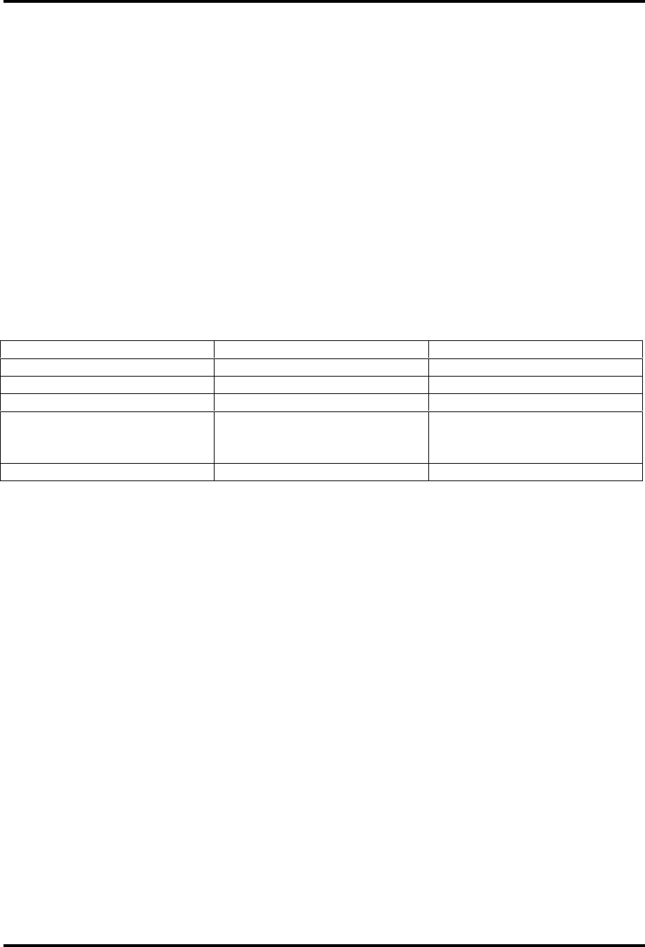
Table 2-1. Driver/Amplifier Assembly Assemblies and Trays
DESIGNATION NUMBER TRAY/ASSEMBLY NAME DRAWING NUMBER
A2 AC distribution assembly 1265-1600
A4 UHF exciter tray 1063301
A9 3-watt amplifier tray 1068203
A6 and A7 250-watt amplifier trays 1044027, low-band;
1044028, mid-band;
1044029, high-band
A14 Bandpass filter assembly --
The exciter/amplifier assembly
(1064946) is connected to the baseband
video and aural inputs. The assembly
also provides connections for the remote
monitoring and operation of the
exciter/amplifier assembly. The UHF
exciter tray (1063301) takes the
baseband aural and video inputs and
produces the visual and aural RF signals
on the channel frequencies. The
combined visual and aural RF output (+7
dBm) of the exciter feeds the 3-watt
amplifier tray (1068203). The 3-watt
amplifier tray contains an automatic gain
control circuit and two 3-watt amplifier
boards. The tray generates the output
level needed to drive the 250-watt
amplifier trays (1044027, low-band;
1044028, mid-band; and 1044029, high-
band).
The output from the 3-watt tray is fed to
the (A10) RF hybrid splitter SMA
connection J1. The RF hybrid splitter
output feeds the RF signal to one of the
250-watt amplifiers directly and, through
(A5) the line stretcher, to the other 250-
watt amplifier. The line stretcher gives
the operator the ability to control the
phase of the output signal that is fed to
one of the 250-watt trays. Each of the
250-watt amplifier trays contains an
amplifier enclosure and feedforward
circuits to achieve an output of 250-watts
peak visual power and 25 watts of aural
power.
In the 250-watt amplifier tray, a forward
power sample from the UHF coupler is
connected to the dual peak detector
board; this board provides a peak-
detected forward sample to the amplifier
control board for metering purposes.
Before exiting the 250-watt amplifier
tray, the RF is fed through a circulator for
the protection of the tray from high
VSWR conditions. The reject port of the
circulator is cabled to the reject

10-kW UHF Transmitter with Chapter 2, System Description
Feedforward Driver
840A, Rev. 0 2-2
load/coupler board; this board supplies
the reflected sample to the dual peak
detector board, single supply. This signal
is then sent to the amplifier control board
for metering purposes. The output of the
250-watt visual amplifier trays is
combined in a UHF tee combiner, and fed
through (A14) a bandpass filter and
(A11) a directional coupler, before being
connected with1/2" heliax to the RF input
jack (A2-A1-J1) of the tube cavity
assembly in the 10-kW amplifier
assembly cabinet. The combined output
of the 250-watt visual amplifier trays
(350 watts) is the level needed to drive
the 10-kW amplifier to 10,000 watts
peak sync visual output.
The main AC input to the
exciter/amplifier assembly is (A2) the AC
distribution panel assembly (1265-1600).
The AC distribution panel assembly
contains a terminal block (TB1) that
connects to the main AC input (208/240
VAC). The terminal block has four metal-
oxide varistors (MOVs) connected across
the input lines for surge and transient
protection. The AC distribution panel
contains CB1, the 40-amp main AC
circuit breaker that distributes the AC
through the circuit breakers CB2 to CB7
to the exciter and amplifier trays.
2.1.2 (A2) 10-kW Diacrode Amplifier
(1299-1100; Appendix A)
The (A11) metering control panel (1293-
1308) on the amplifier assembly provides
the operator with front panel metering
for all voltage (M1 using S1) and current
(M2 using S3) readings that apply to the
tube. The metering control panel also
provides the aural, visual, and reflected
output power readings for the transmitter
using meter M3 with switch S4. The front
panel assembly contains the switches
that control the Operate/Standby (S5)
and Automatic/Manual (S6) operation of
the 10-kW amplifier. When switched to
Operate, the panel supplies the driver
enable (Operate command) to the
exciter/amplifier assembly. The
Automatic/Manual switch selects either
the automatic operation of the
transmitter, which uses the video input
to control the on/off state of the
transmitter, or the Normal front panel
control, manual operation, of the
transmitter. The metering control panel
also provides front panel control, through
switch S8, of the Visual Output Power
level. High-Voltage Enable/Disable switch
S7 controls the high-voltage power
supply from the front panel of the 10-kW
diacrode amplifier. Normal/Exciter Test
switch S10, when in the Exciter Test
position, gives the operator the ability to
operate the exciter/amplifier assembly
without operating the 10-kW amplifier.
Note: The exciter/amplifier assembly
output must be terminated into a
dummy load prior to using this
function.
The metering control panel also has LEDs
on the front panel for a visual indication
of the operating status of the
transmitter: Operate/Standby,
Auto/Manual, High Voltage
Enable/Disable, Driver Mode
Normal/Test, 3-Fault with Fault Reset
Switch (S9), Fault Status Overtemp, and
VSWR Cutback. The front panel has
command status LEDs that indicate,
when they are lit, that the command has
been given. In addition, the front panel
has Operate status LEDs that indicate,
when they are lit, that the command has
been carried out.
The metering control panel of the (A10)
remote control and cabinet interface
assembly provides intercabinet control
and monitoring for the exciter and high-
voltage cabinets. The remote control and
cabinet interface assembly also provides
remote access to the transmitter for
monitoring and control purposes.
The (A6) screen power supply assembly,
60 Hz (1293-1321), in the rear
compartment of the amplifier cabinet,
produces the 500 VDC at 60 mA for the
tube. The (A5) control and bias power
supply assembly (1181-1402) contains

10-kW UHF Transmitter with Chapter 2, System Description
Feedforward Driver
840A, Rev. 0 2-3
two separate power supplies: the control
power supply and the bias power supply.
The control power supply produces the
±12 VDC to the metering circuits (peak
detectors) in the 10-kW amplifier as well
as the fault sensing boards, differential
buffer boards, and control logic boards in
the metering control panel. The bias
power supply produces the -80 VDC bias
voltage to the tube. R1, the bias voltage
adjustment, is located behind the
metering control panel. It sets up the
idling current (1.5 amps), no RF drive, by
adjusting the bias voltage. The (A3)
filament power supply assembly (1299-
1107) produces the 5.2 VDC to the
filament of the tube. The 10-kW
assembly also has (A16) a blower
assembly (1293-1325) that provides the
coolant air flow to the tube mounted in
the cavity assembly.
The RF output of the 10-kW amplifier at
(A2-A1-J2) is fed through a 3-1/8"
hardline to (A2) an output coupler (1020-
1043) that provides a reflected power
sample for fault and VSWR cutback
protection. The output at (A2-A2-J2)
connects to two UHF trap filters. The trap
filters screen out the -3.58-MHz, -4.5-
MHz, +8.08-MHz, and +9.00-MHz
intermodulation products as well as the
second visual harmonic frequency. The
output of the trap filter is fed through
(A18) the output coupler (1020-1002)
that provides a reflected and forward
power sample to (A19) the visual/aural
metering assembly (1162-1402) for
metering purposes. The output of the
coupler is then fed to the antenna.
The visual/aural metering assembly
consists of (A1) a single peak detector
board (1162-1403) for the reflected
output metering. It also contains (A2) a
visual/aural metering board (1161-1103
or 1161-1115) for aural output and visual
output power levels and reflected power
level for VSWR protection.
2.1.3 (A3) High-Voltage Power
Supply Assembly, 208/240 VAC
(1068022; Appendix A)
The (A3) high-voltage power supply
assembly, 208/240 VAC (1068022),
provides the 10-kW amplifier, through
TB4, with the AC voltage that the
assembly needs to operate. It also
supplies the AC needed to operate the
blower assembly, through TB6, and the
high-voltage, using 18 AWG 29-kV
rubber insulated wires, needed to
operate the tube in the 10-kW amplifier.
The high-voltage power supply produces
the 5000 VDC at 4.00 amps, maximum
current (black picture), or 1.5 amps
idling current (no RF drive applied) for
the plate (anode) of the tube. The
assembly contains (A1) the high-voltage
transformer (1293-6103), (A5, A6, and
A7) the three high-voltage rectifier
boards (1293-1101), (A8, A19, A22, and
A23) filter capacitors, and (A16) the
choke that generate the high voltage.
The high-voltage power supply assembly
also contains the power supply metering
boards, the isolation relay boards, the
circuit breakers needed to supply high-
voltage metering, high voltage-on sense,
the power-on sequence, the switching on
and off, and the protection of the high
voltage. The high-voltage power supply,
at TB2, is connected to the 10-kW
assembly that provides the +12 VDC for
metering, switching, and the Enable to
the high-voltage power supply.
2.1.4 (A19) Visual/Aural Metering
Assembly (1162-1402; Appendix A)
The visual/aural metering assembly takes
the forward and reflected power samples
from the (A2-A2) and the (A18) output
couplers. The assembly provides the
metering control panel on the front panel
meters with visual, aural, and reflected
levels for remote monitoring and VSWR
protection.
The visual/aural metering assembly
consists of (A1) a single peak detector
board (1162-1403) for the reflected

10-kW UHF Transmitter with Chapter 2, System Description
Feedforward Driver
840A, Rev. 0 2-4
output metering. It also contains (A2) a
visual/aural metering board (1161-1103
or 1161-1115) for aural output and visual
output power levels and reflected power
levels for VSWR protection.
2.2 Control and Status
Information on the control and status of
this system is provided by control,
status, and LED indicators and meters on
the front panel of the trays. The functions
of these control and status indicators are
described in the following tables.
2.2.1 Exciter/Driver Cabinet
2.2.1.1 UHF Exciter Tray
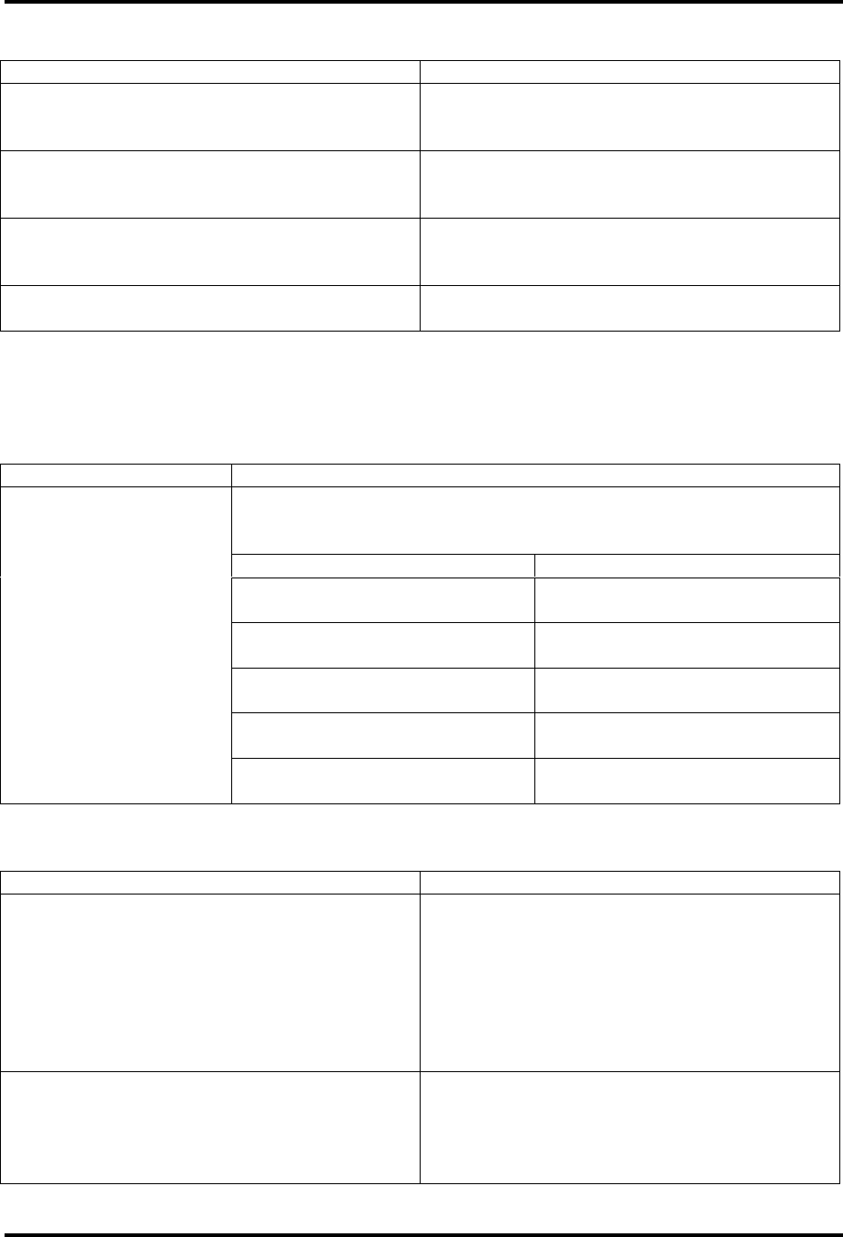
Table 2-2. UHF Exciter Tray Meters
METER FUNCTION
Reads power in terms of a percentage of the calibrated output
power level on the upper scale. The voltage level or frequency
level is read on one of the two bottom scales. A full-scale
reading on the top scale is 120%; 100% is equivalent to the
full-rated 350 watts peak of sync visual. This meter also reads
% Aural Power, % Exciter Power, audio levels, video levels, and
ALC levels.
With Switch S3 in
Position Display
Switch (S3), Meter
Selects the desired ALC voltage
reading, % Exciter Power, % Visual
Power, % Aural Power, video levels, or
audio levels.
Audio
Reads the audio level, ±25 kHz
balanced or ±75 kHz composite, on
the 0 to10 (0 to100 kHz) scale.
Indicates baseband audio if it is
connected to the transmitter and even
with the video + 4.5 MHz SCA input
selected.
ALC
(0 to 10 V) Reads the ALC voltage level, .85
VDC, on the 0 to10 scale
% Exciter
(0 to 120)
Reads the % Exciter Output Power
level needed to attain 100% output of
the transmitter on the top scale
% Aural Power
(0 to 120)
Reads the % Aural Output Power of
the exciter/driver assembly
(100%=45 watts at 10 dB A/V ratio)
on the top scale
% Visual Power
(0-120)
Reads the % Output Power of the
exciter/driver assembly (100%=450
watts peak sync) on the top scale
Meter (A4-A18)
Video
(0-1V) Reads the video level, 1V at white, on
the 0-10 scale

10-kW UHF Transmitter with Chapter 2, System Description
Feedforward Driver
840A, Rev. 0 2-5
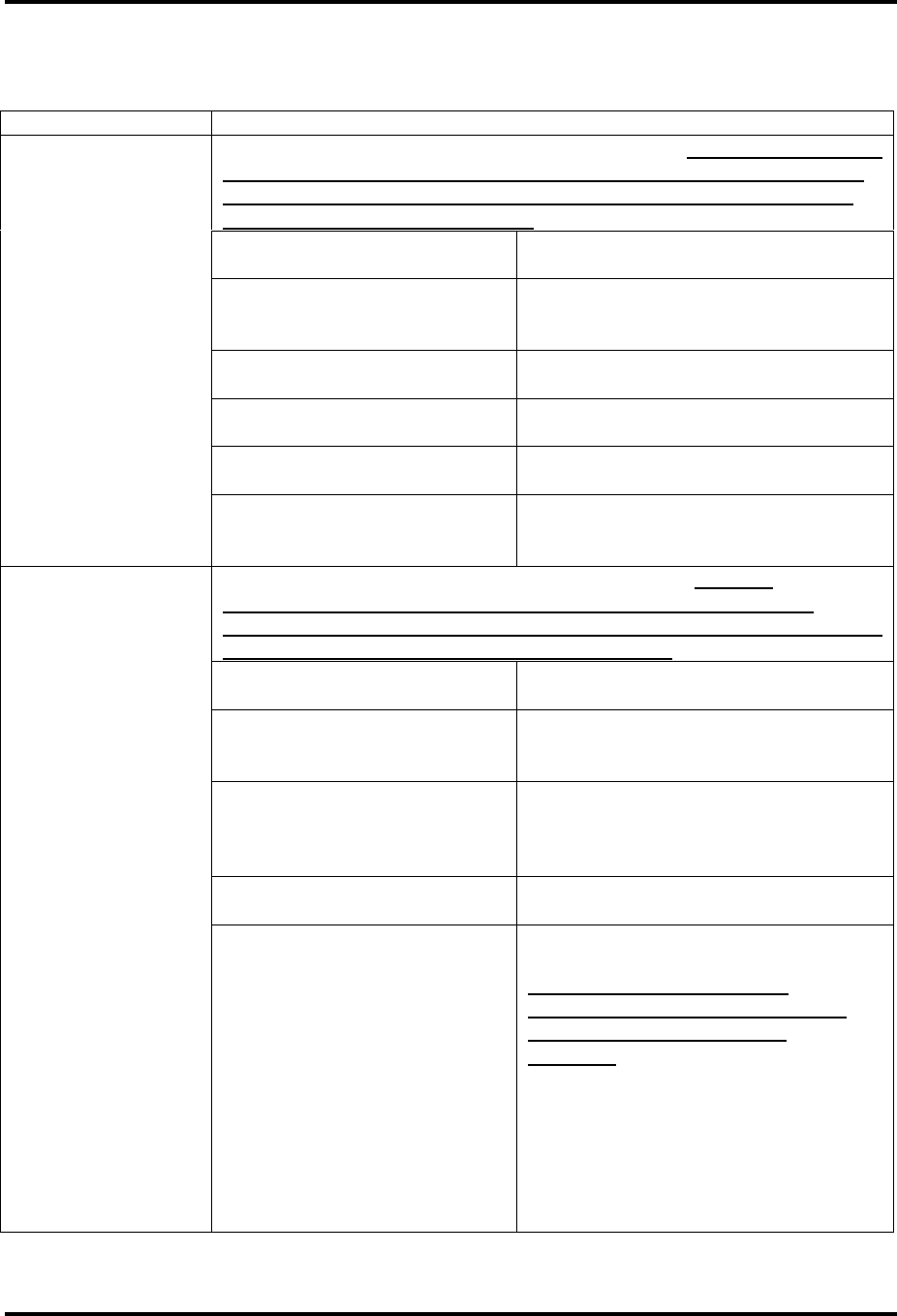
Table 2-3. UHF Exciter Tray Control Switches
SWITCH FUNCTION
Transmitter (S1)
Operate/Standby
The momentary switch (S1) applies a
ground to K1, a latching relay on the
transmitter control board. K1 will switch
either to Operate or to Standby, depending
on which direction S1 is pushed. When
switched to Operate, the low Enable
commands are applied to the four UHF
amplifier trays. The opposite occurs when
S1 is switched to Standby.
Mode Select (S2)
Auto/Manual
The momentary switch (S2) applies a
ground to K2, a latching relay on the
transmitter control board. K2 will switch the
transmitter to Automatic or Manual,
depending on which direction S2 is pushed.
In Automatic, the Video Fault command
from the ALC board will control the
operation of the transmitter. The
transmitter will switch to Standby, after a
slight delay, if the video input is lost and
will switch back to Operate, quickly, when
the video is restored. In Manual, the
transmitter is controlled by the operator
using the front panel Operate/Standby
switch or by remote control.
Power Adjust (R1) The 5 kΩ pot, A20, sets the ALC level on
the ALC board. This sets the output power
for the transmitter.
Table 2-4. UHF Exciter Tray Fault Indicators
FAULT INDICATOR FUNCTION
Video Loss (DS9 Red)
Indicates that the video input to the
transmitter has been lost. The fault is
generated on the ALC board in the UHF
exciter tray.
VSWR Cutback (DS7 Amber)
Indicates that the reflected power level of
the 10-kW transmitter has increased above
15%. This will automatically cut back the
output power level to 15%. The fault is
generated on the transmitter control board
in the UHF exciter tray and is derived from
a peak-detected voltage in the amplifier
cabinet.
10-kW UHF Transmitter with Chapter 2, System Description
Feedforward Driver
840A, Rev. 0 2-6
Table 2-5. UHF Exciter Tray Samples
SAMPLE DESCRIPTION
f(IF) A sample of the visual IF that is taken from
the sample jack on the IF carrier oven
oscillator board
f(IC) A sample of the intercarrier signal that is
taken from the sample jack on the aural IF
synthesizer board
f(s) A sample of the channel oscillator output
that is taken from the sample jack of the
channel oscillator assembly
Exciter O/P An output power sample of the exciter that
is taken from the UHF upconverter board
2.2.2 3-Watt Amplifier Tray
Table 2-6. 3-Watt Amplifier Tray Meter
METER FUNCTION
Selects whether the % Reflected Power, % Input Power, %
Forward Power, power supply voltage, or AGC voltage is to be
viewed on the meter
With Switch S1 in position Display
% Refl (Reflected) Reads the % Reflected Output
Power (<10%)
% Input Reads the % Input Power to
the tray (10%)
% Forward Power Reads the % Forward Power
(100%=3 watts CW)
P.S. Voltage Reads the power supply
voltage (+24 VDC)
Power Meter, Switch
(S1)
AGC Voltage Reads the AGC voltage
(2 VDC)
Table 2-7. 3-Watt Amplifier Tray Fault Indicators
FAULT INDICATOR FUNCTION
Overtemp (DS1)
Indicates that the temperature of the
heatsink, where the Q1 and Q2 current-
pass transistors for the +24 VDC power
supply are mounted, is above 175° F as
sensed by the thermal switch (S2) mounted
to the heatsink. When this fault occurs, the
Enable to the isolation relay is removed
immediately.
AGC Override (DS2)
Indicates that the level out of the 3-watt
amplifier board has requested the AGC
circuit to exceed the AGC limits. The fault is
generated on the AGC board in the 3-watt
amplifier tray.

10-kW UHF Transmitter with Chapter 2, System Description
Feedforward Driver
840A, Rev. 0 2-7
2.2.3 250-Watt Amplifier Trays
Table 2-8. 250-Watt Amplifier Tray Meters
METER FUNCTION
Reads power in terms of a percent of the calibrated power
output value. A full-scale reading is 100%, which is equivalent
to the full-rated 250 watts peak of sync visual + aural output
power. Also reads % Reflected Power, power supply voltage
levels, and AGC voltage levels.
With Switch S1 in
Position Display
Switch (S1), Meter Selects the desired % Power or the
voltage reading
% Output Pwr
Reads the % Output Power of the
tray (100%=250 watts peak of sync
visual with -10 dB aural on the top
scale)
% Refl (Reflected) Reads the % Reflected Output Power
of the tray (<10%)
Meter (A12)
Power Supply Reads the power supply voltage,
+26.5 VDC, on the middle scale
Table 2-9. 250-Watt Amplifier Tray Status Indicators
STATUS INDICATOR FUNCTION
Enable (DS1 Green) Indicates that an Enable, Operate,
command, is applied to the UHF amplifier
tray from the selected UHF exciter tray
Overtemp (DS2 Red)
Indicates that the temperature of (A1-A7
and A1-A8), one or both of the two thermal
switches mounted on the heatsink assembly
for the output amplifiers, is above 175° F.
When this fault occurs, the Enable to the
switching power supply in the affected
amplifier tray is removed immediately and
will shut down.
10-kW UHF Transmitter with Chapter 2, System Description
Feedforward Driver
840A, Rev. 0 2-8
2.2.4 10-kW Amplifier Assembly Metering Control Panel
Table 2-10. 10-kW Amplifier Assembly Meters
METER FUNCTION
Reads DC voltage (a full-scale reading is 1 volt) Note: A multiplier,
whose value is dependent on which position switch S1 is in,
must be applied. The multiplier that is needed is marked in
parentheses near the switch.
With Switch S1 in
Position Display
Switch (S1) Voltage Meter Selects the desired plate voltage,
screen voltage, bias voltage, and
filament voltage readings
Plate (x10 k) Reads the plate voltage (typical
reading is 5200 volts)
Screen (x1 k) Reads the screen voltage (typical
reading is 500 volts)
Bias (x1 k) Reads the bias voltage (typical
reading is 85 volts)
Voltage Meter
(M1)
Filament (x10) Reads the filament voltage (typical
reading is 5.2 volts; black heat
voltage is 1.5 volts)
Reads DC current (a full-scale reading is 50 mA) Note: A
multiplier, whose value is dependent on which position
switch S2 is in, must be applied. The multiplier that is needed
is marked in parentheses near the switch.
With Switch S2 in
Position Display
Switch (S2), Current
Meter
Selects the desired plate current,
screen current, and control grid
current readings
Plate (x100)
Reads the plate current (a
typical reading is 1.5 amps, no
RF drive, to 4 amps; 100%
power, sync-only)
Screen (x2) Reads the screen current (typical
reading is <60 mA)
Current Meter
(M2)
Control Grid (x1)
Reads the control grid current
(typical reading is 0 mA to 5 mA)
Note: The meter reverse
switch (S3) must be switched
down to give an upscale
reading.

10-kW UHF Transmitter with Chapter 2, System Description
Feedforward Driver
840A, Rev. 0 2-9
METER FUNCTION
Reads power in terms of a percent of the calibrated power value (a
full-scale reading will be 100%)
With Switch S4 in
Position Display
Switch (S4), Power Meter
Selects the desired visual output
power, aural output
power and the reflected
output power readings
Visual Output Reads the visual output power of the
10-kW amplifier (100%)
Aural Output Reads the aural output power of the
10-kW amplifier (100%)
Power Meter
(M3)
Reflected Reads the reflected visual output
power from the 10-kW amplifier
(<10%)
Table 2-11. 10-kW Amplifier Assembly Switches
SWITCH FUNCTION
Meter Polarity (S3)
Changes the polarity of the measured
current applied to the meter. To properly
read the plate I and screen I, the meter
polarity switch must be in the Up (+)
position to give an upscale reading. To read
the control grid I properly, the switch must
be in the Down (-) position. The normal
setting of the meter reverse switch is the
Up position.
Transmitter (S5)
The momentary switch (S5) applies a
ground to K3, a latching Operate/Standby
relay on (A7) the transmitter control board.
K3 switches either to Operate or to Standby
depending on which direction S5 is pushed.
When S5 is switched to Operate, a low
Operate (Enable) command is applied to
(A1) the control logic board to start the
automatic turn-on procedure for the 10-kW
transmitter. The opposite occurs when S5 is
switched to Standby.
Mode Select (S6)
The momentary switch (S6) applies a
ground to K1, a latching Auto/Manual relay
on (A7) the transmitter control board. K1
switches the transmitter to Automatic or
Manual depending on which direction S6 is
pushed. In Automatic, a video fault
command from the upconverter tray
controls the transmitter. The transmitter
switches to Standby if the video input is lost
and will switch to Operate when the video is
reapplied. In Manual, the transmitter is
controlled through the normal automatic

10-kW UHF Transmitter with Chapter 2, System Description
Feedforward Driver
840A, Rev. 0 2-10
SWITCH FUNCTION
turn-on sequence with the operator using
the front panel controls or remote
control.
HV (High Voltage) (S7)
Enable/Disable
When the switch is enabled (Up), the
magnetic latching relay (K1) on (A1) the
control logic board will engage. The high-
voltage enable indicator will light along with
the High-Voltage Request LED. The High-
Voltage On command to the high-voltage
relay will be applied at the proper time
during the automatic turn-on sequence.
When switched to Disable, the High-Voltage
On command will be removed, disabling the
high voltage and causing the Automatic Off
Cycle sequence to occur.
Output Power (S8)
Adjusts the output power level of the
transmitter by raising or lowering the ALC
level on the visual ALC/AGC board in the
UHF exciter tray. This control is used to
compensate for the small, everyday
variations in the output power level. If a
major variation occurs, a problem exists.
After the problem has been repaired, the
output power level adjustment may also
require a readjustment to the AGC
voltage levels (refer to the system setup
procedures in Chapter 3 of this manual).
Fault Reset (S9)
As a fault occurs in the transmitter, the
Fault LED will flash on and then go off as
the transmitter automatically resets itself
to try to eliminate the problem. If the
problem remains, the transmitter will try to
reset itself three times in approximately one
minute. After this, the Three-Fault indicator
will remain lit and the transmitter will
automatically shut down. When the problem
that caused the fault is found and repaired,
the Fault Reset switch S9 must be set
before the transmitter will recycle.
Driver Mode (S10)
Normal/Test
When the switch is in Normal (Up), the
transmitter operates normally. When the
switch is in Test (Down), the magnetic
latching relay (K4) on (A7) the transmitter
control board supplies the driver Enable to
the exciter/driver assembly. This allows the
operation of the exciter/driver assembly
without requiring the 10-kW amplifier
section to be on. When this function is
being performed, the driver must be
terminated into a dummy load and the high
voltage must be disabled.

10-kW UHF Transmitter with Chapter 2, System Description
Feedforward Driver
840A, Rev. 0 2-11
Note: The circuit breakers discussed
in Table 2-12 are on the AC
distribution panel of the 10-kW
amplifier and the high-voltage power
supply assembly. For the other
circuit breakers on the panel to
operate, the main AC and the control
circuit breakers must both be
switched on.
Note: When the preceding command
is completed, the automatic turn-on
procedure will cycle the transmitter
through the command status and
corresponding operating status steps
from left to right on the front panel
LEDs. The Command Status indicator
shows that a command has been
given and the Operating Status
indicator shows that the command
has been carried out.
Table 2-12. 10-kW Amplifier Assembly Command Status Indicators
STATUS INDICATOR FUNCTION
Blower (DS8)
Indicates that the Blower On command
(Enable) has been given by the control
logic. The blower is controlled by the
filament power supply control board that
sends a low Enable command to the
isolation relay on the blower assembly. The
relay energizes and the closed contacts
apply 220 VAC to the blower contactor K1.
If the blower circuit breaker is turned on,
the 208/240 VAC 3 phase is applied to (A1)
the blower and the unit will operate.
Filament (DS9)
Indicates that the blower is on and that the
Filament On command (Enable) has been
given to the filament power supply
assembly. If the black heat has been
applied to the filament for at least 10
minutes, the Operate command activates
the ramp-up phase of the filament power
supply.
Bias (DS10)
Indicates that the filament voltage has been
at 5.2 volts for approximately 20 seconds
and the Bias On command (Enable) has
been given to the isolation relay (A3) on the
control and bias power supply assembly.
The relay energizes and, when the bias
circuit breaker is turned on, applies 220
VAC to the bias power supply board.
High Voltage (DS11)
Indicates that the bias voltage is on and the
High Voltage On command (Enable) has
been given to the isolation relay (A24)
in the high-voltage power supply assembly.
The relay energizes and applies +12 VDC to
the (A18) isolation relay and (K1) the
contactor control relay that control the

10-kW UHF Transmitter with Chapter 2, System Description
Feedforward Driver
840A, Rev. 0 2-12
STATUS INDICATOR FUNCTION
step-start and high-voltage contactors.
When the main AC and HV circuit breakers
are turned on, 208/240 VAC is applied to
the transformer of the high-voltage power
supply.
Screen (DS12)
Indicates that the high voltage (plate
voltage) is on and the Screen On command
(Enable) has been given to the isolation
relay (A7) mounted in the screen power
supply assembly. The relay energizes and,
when the screen circuit breaker is switched
on, applies 220 VAC through the Sola 60 Hz
regulator to the transformer (T1) that is
part of the screen power supply.
RF Request (DS13)
Indicates that the tube has all of the
voltages applied and that the RF On
command (Enable) has been given to
enable the exciter/driver assembly that
applies the RF drive to the 10-kW amplifier
Table 2-13. 10-kW Amplifier Assembly Operating Status Indicators
STATUS INDICATOR FUNCTION
Blower (DS16)
Indicates that the blower is on. The
quantity of air flow through the exhaust
stack is measured by the air pressure
sensor.
Filament (DS17)
Indicates that the above step is complete
and that the filament voltage is on. This is
indicated when the filament voltage on
sense at J12-11 of the control logic board is
low.
Bias (DS18)
Indicates that the above steps are complete
and the bias voltage is on. This is indicated
when the bias on sense at J13-2 of the
control logic board is low.
High Voltage (DS19)
Indicates that the above steps are complete
and the high voltage is on. This is indicated
when the high voltage on sense at J13-8 of
the control logic board is low.
Screen (DS20)
Indicates that the above steps are complete
and the screen voltage is on. This is
indicated when the screen voltage on sense
at J13-14 of the control logic board is low.
RF Present (DS21)
Indicates that the above steps are complete
and that there is an RF output from the
transmitter. This is indicated when there is
a forward power sample fed to (J15 - 7 and
6) of the transmitter control board.

10-kW UHF Transmitter with Chapter 2, System Description
Feedforward Driver
840A, Rev. 0 2-13
Table 2-14. 10-kW Amplifier Assembly Fault Indicators
FAULT INDICATOR FUNCTION
Over Temp (DS22)
Indicates that the air temperature in the
exhaust stack is above 200° F as sensed
by the thermal switch (A15-S1) mounted
there. When this fault occurs, the voltages
will be immediately removed from the tube,
but the blower will continue running to
cool the transmitter.
VSWR Cutback (DS23)
Indicates that the reflected output power
of the transmitter, as sampled at (J15 - 1
and 2) of the transmitter control board, has
exceeded 10%; this causes the 10-kW
amplifier to cut back the output power level
needed to maintain a 10% visual reflected
level. If the reflected output power level
exceeds 15%, a VSWR fault will occur and
cause the transmitter to shut down.

10-kW UHF Transmitter with Chapter 2, System Description
Feedforward Driver
840A, Rev. 0 2-14
2.3 Remote Control Interface
Connections
The remote control interface
connections for the 840A
transmitter are listed in the
following tables.
Table 2-15. 10-kW Amplifier Assembly Remote Control Interface Connections
FUNCTION REMOTE JACK/PIN
NUMBER INTERFACE TYPE
Interlock (Total Shutdown) J1-1
Interlock (Total Shutdown)
Rtn J1-2
May be connected to a
remote interlock
Interlock (Drv, Scrn, and
high voltage) J1-3
Interlock (Drv, Scrn, and
high voltage) Rtn J1-4
May be connected to a
remote interlock
Note: The jumper plug (1176-1019), with jumpers connected between pins 1
and 2 and 3 and 4, must be plugged into jack (J1) for the normal operation of
the transmitter.
Remote Status Indications
Transmitter Operate Ind J4-1 50 mA max current sink
Transmitter Operate Rtn J4-2
Transmitter Auto Mode Ind J4-3 50 mA max current sink
Transmitter Auto Mode Rtn J4-4
High Voltage Enable Ind J4-5 50 mA max current sink
High Voltage Enable Ind Rtn J4-6
Fault Ind J4-7 50 mA max current sink
Fault Ind Rtn J4-8
RF Present Ind J4-9 50 mA max current sink
RF Present Ind Rtn J4-10
Overtemp Ind J4-11 50 mA max current sink
Overtemp Ind Rtn J4-12
VSWR Cutback Ind J4-14 50 mA max current sink
VSWR Cutback Ind Rtn J4-15
Video Fault Ind J4-16 50 mA max current sink
Video Fault Ind Rtn J4-17

10-kW UHF Transmitter with Chapter 2, System Description
Feedforward Driver
840A, Rev. 0 2-15
FUNCTION REMOTE JACK/PIN
NUMBER INTERFACE TYPE
Remote Commands
Operate Cmd J5-1 Contact closure
Operate/Standby Cmd Rtn J5-2
Standby Cmd J5-3 Contact closure
Auto Mode Select Cmd J5-4 Contact closure
Auto/Manual Select Cmd Rtn J5-5
Manual Select Cmd J5-6 Contact closure
H.V. Enable Cmd J5-7 Contact closure
H.V. Enable/Disable Cmd
Rtn J5-8
H.V. Disable Cmd J5-9 Contact closure
Power Raise Cmd J5-10 Contact closure
Power Raise/Lower Cmd Rtn J5-11
Power Lower Cmd J5-12 Contact closure
Fault Reset Cmd J5-13 Contact closure
Fault Reset Rtn J5-14
Remote Metering
Reflected Power Metering J6-1
Reflected Power Rtn J6-2 1V full scale at 1 kΩ source
resistance
Visual Forward Power
Metering J6-3
Visual Forward Power Rtn J6-4
1V full scale at 1 kΩ source
resistance
Plate Current Metering J6-5
Plate Current Rtn J6-6 1V full scale at 1 kΩ source
resistance
Screen Current Metering J6-7
Screen Current Rtn J6-8 1V full scale at 1 kΩ source
resistance
Control Grid Current
Metering J6-9
Control Grid Current Rtn J6-10
1V full scale at 1 kΩ source
resistance
Plate Voltage Metering J6-11
Plate Voltage Rtn J6-12 1V full scale at 1 kΩ source
resistance
Screen Voltage Metering J6-13
Screen Voltage Rtn J6-14 1V full scale at 1 kΩ source
resistance
Bias Voltage Metering J6-15 1V full scale at 1 kΩ source
resistance

10-kW UHF Transmitter with Chapter 2, System Description
Feedforward Driver
840A, Rev. 0 2-16
FUNCTION REMOTE JACK/PIN
NUMBER INTERFACE TYPE
Bias Voltage Rtn J6-16
Filament Voltage Metering J6-17
Filament Voltage Rtn J6-18 1V full scale at 1 kΩ source
resistance
Aural Forward Power
Metering J6-20
Aural Forward Power Rtn J6-21
1V full scale at 1 kΩ source
resistance
Note: The remote control interface connections for the 10-kW amplifier connect
to jacks J1, J4, J5, and J6 of (A10) the remote control and cabinet interface
assembly mounted to the rear and at the top of the amplifier cabinet.
The remote connections listed in Table 2-
16 are only made if the (A12) A/V input
and remote interface assembly are
present in the system. The remote
connections are made to jacks J9 and J10
on the assembly. Refer to the
interconnect drawing (1064945) for the
proper pin remote connections.
Table 2-16. UHF Exciter Remote Control Interface Connections
FUNCTION REMOTE CONTROL/PIN
NUMBER INTERFACE TYPE
Transmitter Enable Interlock J9-21
Transmitter Enable Interlock
Rtn J9-22
J9-21 and 22 must be
jumpered together for
normal operation; (1176-
1038) jumper jack should
be used
Remote Control Commands
Transmitter Standby
(Disable) J9-9 Contact closure
Transmitter
Standby/Operate Rtn J9-10
Transmitter Operator
(Enable) J9-11 Contact closure
Transmitter Manual J9-15 Contact closure
Transmitter Auto/Manual
Rtn J9-16
Transmitter Auto J9-17 Contact closure
Power Level Raise (optional) J9-27 Contact closure
Pwr Lvl Raise/Lower Rtn
(optional) J9-28
Power Level Lower
(optional) J9-29 Contact closure
Modulator Select (optional) J9-31 Contact closure

10-kW UHF Transmitter with Chapter 2, System Description
Feedforward Driver
840A, Rev. 0 2-17
FUNCTION REMOTE CONTROL/PIN
NUMBER INTERFACE TYPE
Modulator Select Rtn
(optional) J9-32
Remote Status Indications
Transmitter Operate
(Enable) Ind J9-12 50 mA max current sink
Operate/Standby Ind Return J9-13
Transmitter Standby
(Disable) Ind J9-14 50 mA max current sink
Transmitter Auto Indicator J9-18 50 mA max current sink
Auto/Manual Indicator
Return J9-19
Transmitter Manual
Indicator J9-20 50 mA max current sink
VSWR Cutback Indicator J9-23 50 mA max current sink
VSWR Cutback Indicator
Return J9-24
Video Loss (Fault) Indicator J9-25 50 mA max current sink
Video Loss (Fault) Ind Rtn J9-26
Receiver Fault (optional) J9-30
Remote Metering
Reflected Power J9-5
Reflected Power Rtn J9-6 1V full scale at 1 kW source
resistance
Exciter Output Power J9-7
Exciter Output Power Rtn J9-8 1V full scale at 1 kW source
resistance

10-kW UHF Transmitter with Chapter 2, System Description
Feedforward Driver
840A, Rev. 0 2-18
Table 2-17. UHF Amplifier Tray Remote Control Interface Connections
FUNCTION REMOTE JACK/PIN
NUMBER INTERFACE TYPE
Metering
3-watt Fwd Pwr Mtrg J10-16 1V at 1KΩ source resistance
3-watt Fwd Pwr Mtrg Rtn J10-17 1V at 1KΩ source resistance
250-watt amp A7 Fwd Pwr
Mtrg J10-6 1V at 1KΩ source resistance
250-watt amp A7 Fwd Pwr
Mrtg Rtn J10-7 1V at 1KΩ source resistance
250-watt amp A7 Refl Pwr
Mtrg J10-8 1V at 1KΩ source resistance
250-watt amp A7 Refl Pwr
Mtrg Rtn J10-9 1V at 1KΩ source resistance
250-watt amp A6 Fwd Pwr
Mtrg J10-1 1V at 1KΩ source resistance
250-watt amp A6 Fwd Pwr
Mtrg Rtn J10-2 1V at 1KΩ source resistance
250-watt amp A6 Refl Pwr
Mtrg J10-3 1V at 1KΩ source resistance
250-watt amp A6 Refl Pwr
Mtrg Rtn J10-4 1V at 1KΩ source resistance
Note: These remote connections are made only if the optional (A12) A/V input
and remote interface assembly are present in the system. The remote
connections are made to jacks J9 and J10 on the assembly. Refer to the
interconnect drawing (1064945) for the proper pin remote connections.