UBS Axcera 840A 10,000-watt UHF solid state television transmitter User Manual Chapter 3
UBS-Axcera 10,000-watt UHF solid state television transmitter Chapter 3
Contents
Chapter 3

10-kW UHF Transmitter with Chapter 3, Installation and
Feedforward Drive Setup Procedures
840A, Rev. 0 3-1
Chapter 3
Installation and Setup Procedures
There are special considerations that
need to be taken into account before the
840A can be installed. For example, if the
installation is completed during cool
weather, a heat-related problem may not
surface for many months, suddenly
appearing during the heat of summer.
This section provides planning
information for the installation and set up
of the transmitter.
3.1 Site Considerations
The 840A transmitter requires two main
AC input lines, a 3-phase 208/240 VAC,
60 Hz input of at least 100 amp rating
that connects to the high-voltage power
supply assembly and a single-phase
208/240 VAC, 60 Hz input of at least 40
amp rating that connects to the
exciter/driver assembly. Make sure that
the proposed site has the necessary
voltage requirements.
The cabinets should be positioned with
consideration given for adequate air
intake and exhaust. In addition,
installation planning should take into
account the amount of space required for
the opening of the front of the metering
control panel on the 10-kW amplifier; the
opening of the rear doors on the 10-kW
amplifier and exciter/driver cabinets;
access to the trays, including sliding
them out for testing; the main AC hook-
up to the high-voltage power supply
assembly; and the installation of the
output transmission line, including the
trap filters and the directional coupler.
The 10-kW amplifier cabinet contains a
tube cavity air exhaust stack that is a
10.5-inch chimney mounted on the roof
of the cabinet. Forced air flows though
this chimney from the blower assembly
that cools the tube mounted in the cavity
assembly (1,100 CFM at 30° C rise).
The 10-kW amplifier cabinet also has two
exhaust fans, rated at 240 CFM, mounted
in the top cover assembly of the cabinet.
Air intake for the tube cavity blower
assembly is through the large filter
mounted on the bottom rear of the
cabinet.
The high-voltage power supply cabinet
has two exhaust fans, each rated at 550
CFM, mounted in the top cover assembly
of the cabinet. Air intake for the cabinet
is through the two filters mounted on
each side of the cabinet.
The 840A is designed and built to provide
long life with a minimum of maintenance.
The environment in which it is placed is
important and certain precautions must
be taken. The three greatest dangers to
the transmitter are heat, dirt, and
moisture. Heat is usually the greatest
problem, followed by dirt, and then
moisture. Over-temperature can cause
heat-related problems such as thermal
runaway and component failure. Each
amplifier tray in the transmitter contains
a thermal interlock protection circuit that
will shut down that tray until the
temperature drops to an acceptable level.
A suitable environment for the
transmitter can enhance the overall
performance and reliability of the
transmitter and maximize revenues by
minimizing down time. A properly
designed facility will have an adequate
supply of cool, clean air, free of airborne
particulates of any kind, and no
excessive humidity. An ideal environment
will require temperature in the range of
40° F to 70° F throughout the year,
reasonably low humidity, and a dust-free
room. It should be noted that this is
rarely if ever attainable in the real world.
However, the closer the environment is
to this design, the greater the operating
capacity of the transmitter.

10-kW UHF Transmitter with Chapter 3, Installation and
Feedforward Drive Setup Procedures
840A, Rev. 0 3-2
The fans and blowers designed and built
into the transmitter will remove the heat
from within the trays, but additional
means are required for removing this
heat from the building. To achieve this, a
few considerations should be taken into
account. The first step is to determine
the amount of heat to be removed. There
are generally three sources of heat that
must be considered. The first and most
obvious is the heat from the transmitter
itself. This can be determined by
subtracting the average power to the
antenna (6950 watts) from the AC input
power (25,000 watts). This number in
watts (18,050) is then multiplied by
3.41, which gives 61,550, the BTUs to be
removed every hour. 12,000 BTUs per
hour equals one ton, so a 6-ton air
conditioner will cool a 10-kW transmitter
that is vented into the room. If the air
exhaust will be vented externally, a 1.5-
ton air conditioner will be needed to
properly cool the transmitter.
The second source of heat is other
equipment in the same room. This
number is calculated in the same way as
the equation for BTUs. The third source
of heat is equally obvious but not as
simple to calculate. This is the heat
coming through the walls, roof, and
windows on a hot summer day. Unless
the underside is exposed, the floor is
usually not a problem. Determining this
number is usually best left up to a
qualified HVAC technician. There are far
too many variables to even estimate this
number without detailed drawings of the
site showing all construction details. The
sum of these three sources is the total
amount of heat that must be removed.
There may be other sources of heat, such
as personnel, and all should be taken into
account.
Now that the amount of heat that must
be removed is known, the next step is to
determine how to accomplish this. The
options are air conditioning, ventilation,
or a combination of the two. Air
conditioning is always the preferred
method and is the only way to create
anything close to an ideal environment.
Ventilation will work if the ambient air
temperature is below 100° F, or about
38° C, and the humidity is be kept at a
reasonable level. In addition, the air
stream must be adequately filtered to
ensure that no airborne particulates of
any kind will be carried into the
transmitter. The combination of air
conditioning for summer and ventilation
during the cooler months is acceptable
when the proper cooling cannot be
obtained through the use of ventilation
alone and using air conditioning
throughout the year is not feasible.
Caution: The operation of air
conditioning and ventilation
simultaneously is not recommended.
This can cause condensation in
transmitters. For tube type
transmitters, this can be especially
serious if the condensation forms in
the tube cavity and creates
damaging arcs.
The following precautions should be
observed when using air conditioning
systems:
1. Air conditioners have an ARI
nominal cooling capacity rating. In
selecting an air conditioner, do not
assume that this number can be
equated to the requirements of
the site. Make certain that the
contractor uses the actual
conditions that are to be
maintained at the site in
determining the size of the air
conditioning unit. With the desired
conditioned room temperature
under 80° F, the unit must be
derated, possibly by a substantial
amount.
2. Do not have the air conditioner
blowing directly onto the
transmitter. Condensation may
occur on, or worse in, the

10-kW UHF Transmitter with Chapter 3, Installation and
Feedforward Drive Setup Procedures
840A, Rev. 0 3-3
transmitter under certain
conditions.
3. Do not isolate the front of the
transmitter from the back with the
thought of air conditioning only
the front of the unit. Cooling air is
drawn in at the front of all
transmitters and in the front and
back of others. Any attempt to
isolate the front from the rear will
adversely affect the cooling air
flow.
4. Interlocking the transmitter with
the air conditioner is
recommended to keep the
transmitter from operating without
the necessary cooling.
5. The periodic cleaning of all filters
is a must.
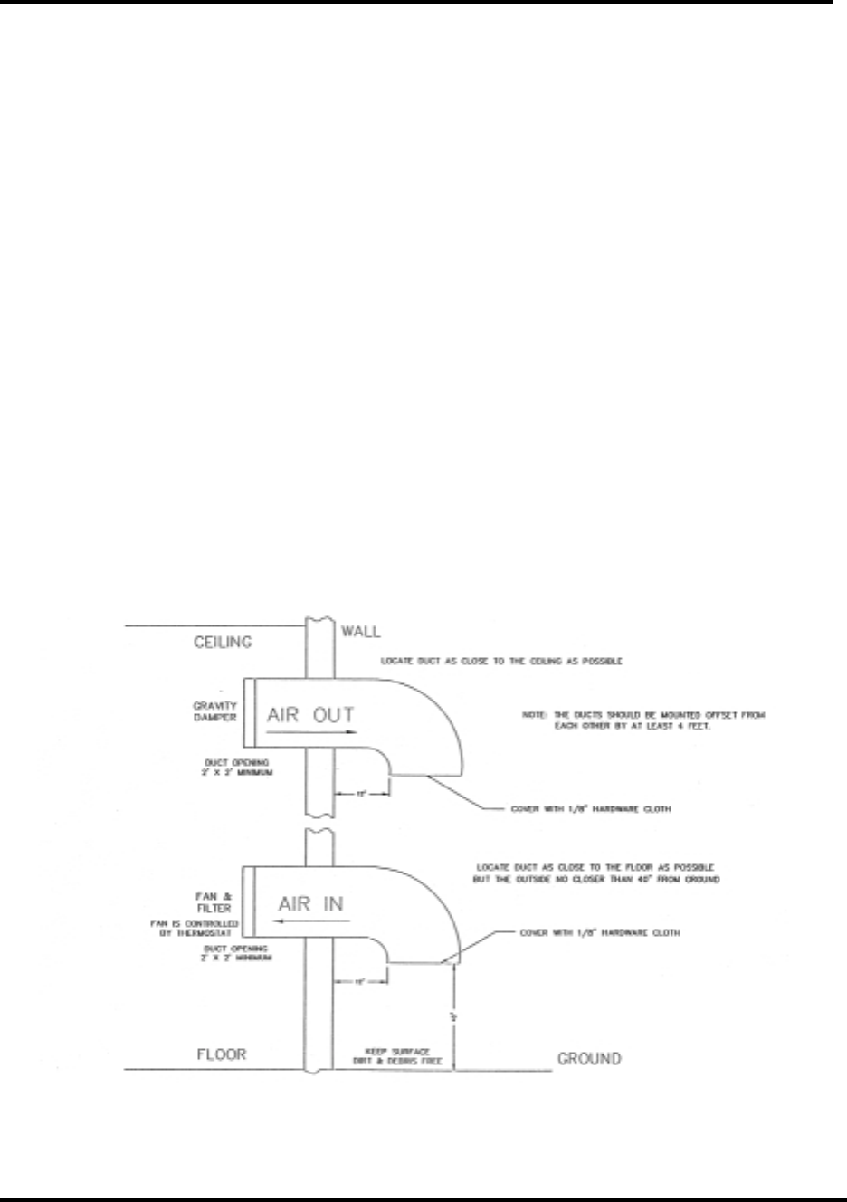
When using ventilation alone, the
following general statements apply:
1. The blower and its filters should
be on the inlet. This will pressurize
the room and prevent dirt from
entering the transmitter.
2. The inlet and outlet vents should
be on the same side of the
building, preferably the leeward
side. As a result, the pressure
differential created by wind will be
minimized. Only the outlet vent
should be released through the
roof.
3. The inlet and outlet vents should
be screened with 1/8" hardware
cloth (preferred) or galvanized
hardware cloth (acceptable).
4. Cooling air should enter the room
as low as practical but in no case
higher than four feet above the
floor. The inlet must be located
where dirt, leaves, snow, etc., will
not be carried in with the cooling
air.
5. The exhaust should be located as
high as possible. Some ducting is
usually required to insure the
complete flushing of heated air
with no stagnant areas.
6. The filter area must be adequate
to insure a maximum air velocity
of 300 feet per minute through the
filter. This is not a conservative
number but a never-exceed
number. In a dusty or remote
location, this number should be
reduced to 150 CFM.
7. The inlet and outlet(s) must have
automatic dampers that close any
time the ventilation blower is off.
8. In those cases in which
transmitters are regularly off for a
portion of each day, a
temperature-differential sensor
that controls a small heater must
be installed. This sensor will
monitor inside and outside
temperatures simultaneously. If
the inside temperature falls to
within 5° F of the outside
temperature, the heater will come
on. This will prevent condensation
when the ventilation blower comes
on and should be used even in the
summer.
9. A controlled-air bypass system
must be installed to prevent the
temperature in the room from
falling below 40° F when the
transmitter is operating.
10. The blower should have two
speeds, which are thermostatically
controlled, and interlocked with
the transmitter.
11. The blower on high speed must be
capable of moving the required
volume of air into a half inch of
water pressure at the required
elevation. The free air delivery
method must not be used.
10-kW UHF Transmitter with Chapter 3, Installation and
Feedforward Drive Setup Procedures
840A, Rev. 0 3-4
12. Regular maintenance of the filters,
if used, can not be
overemphasized.
13. Tube transmitters should not rely
on the internal blower to exhaust
cooling air at elevations above
4000 feet. For external venting,
the air vent on the cabinet top
must be increased to an 8"
diameter for a 1 kW transmitter
and to 15" for a 10-kW
transmitter. An equivalent
rectangular duct may be used but,
in all cases, the outlet must be
increased in area by 50% through
the outlet screen.
14. It is recommended that a site plan
be submitted to ADC for
comments before installation
commences.
To calculate the blower requirements,
filter size, and exhaust size if the total
load is known in watts, 2000 CFM into
1/2" of water will be required for each
5000 watts. If the load is known in BTUs,
2000 CFM into 1/2" of water will be
required for each 17,000 BTUs. The inlet
filter must be a minimum of seven
square feet, larger for dusty and remote
locations, for each 5000 watts or 17,000
BTUs. The outlet for the exhaust must be
at least four square feet at the exhaust
screen for each 5000 watts or 17,000
BTUs.
The information presented in this section
is intended to serve only as a general
guide and may need to be modified for
unusually severe conditions. A
combination of air conditioning and
ventilation should not be difficult to
design (see Figure 3-1). System
interlocking and thermostat settings
should be reviewed with ADC. As with
any equipment installation, it is always
good practice to consult the
manufacturer when questions arise. ADC
can be contacted at (724) 941-1500.
Figure 3-1. 1 kW Minimum Ventilation Configuration
10-kW UHF Transmitter with Chapter 3, Installation and
Feedforward Drive Setup Procedures
840A, Rev. 0 3-5
3.2 Unpacking the Cabinets and
Trays
Note: Air conditioning and any
related heat-exhaust ducts should be
in place before continuing with the
installation of the transmitter.
Thoroughly inspect the cabinets and all
other materials upon their arrival. ADC
certifies that upon leaving our facility the
equipment was undamaged and in proper
working order. The shipping containers
should be inspected for obvious damage
that indicates rough handling. Check for
dents and scratches or broken switches,
meters, or connectors. Any claims
against in-transit damage should be
directed to the carrier. Inform ADC as to
the extent of any damage as soon as
possible.
Remove the exciter/amplifier cabinet with
trays, the 10-kW amplifier cabinet, the
high-voltage power supply cabinet,
conduit pieces, directional couplers,
output trap filter, all of the hard line and
coaxial cables, as well as any installation
material, from the crates and boxes.
Remove the straps that hold the
exciter/amplifier cabinet to the shipping
skid and slide the cabinet from the skid.
Remove the plastic wrap and foam
protection from around the cabinet. Do
not remove any labeling or tags from any
cables or connectors, as these are
identification markers which make re-
assembly of the transmitter much easier.
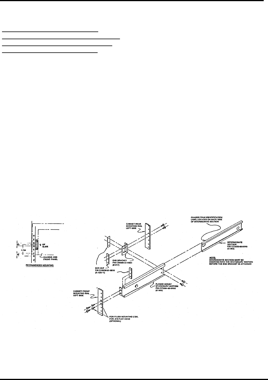
Remove the two L-brackets, mounted on
the front panel rails, that held the trays
in place during shipment. The trays are
mounted in the cabinet using Chassis
Trak cabinet slides (see Figure 3-2).
Open the rear door and inspect the
interior for packing material. Carefully
remove any packing material that is
found. Slowly slide each tray in and out
to verify that they do not rub against
each other and have no restrictions to
free movement. Adjustments may be
necessary and are accomplished by
loosening the front cabinet slide
mounting bolts and moving the tray up
or down as needed. Inspect the trays for
any loose hardware or connectors and
tighten where needed.
Figure 3-2. Chassis Trak Cabinet Slides
Remove the straps that hold the 10-kW
amplifier cabinet to the shipping skid and
slide the cabinet from the skid. Remove
the plastic wrap and foam protection
from around the cabinet. Do not remove
any labeling or tags from any cables or

10-kW UHF Transmitter with Chapter 3, Installation and
Feedforward Drive Setup Procedures
840A, Rev. 0 3-6
connectors, as these are identification
markers that make assembly of the
transmitter much. Open the metering
control panel and the rear door of the 10-
kW amplifier. Inspect the interior for any
packing material and carefully remove
any that is found.
Remove the straps that hold the high-
voltage power supply cabinet to the
shipping skid and slide the cabinet from
the skid. Remove the plastic wrap and
foam protection from around the cabinet.
Do not remove any labeling or tags from
any cables or connectors, as these are
identification markers that make
assembly of the high-voltage power
supply and its connection to the 10-kW
amplifier cabinet much easier.
3.3 Installation of the Cabinets and
Trays
The cabinets should be positioned with
the exciter/amplifier cabinet to the left of
the 10-kW amplifier cabinet when the
operator is facing the front of the
cabinets. The high-voltage power supply
cabinet should be placed at the rear of
the 10-kW amplifier cabinet.
Note: Refer to the specific floor plan
or the racking plan for the site for
information on cabinet placement.
The cabinets should be mounted,
using bolts, to the floor of the site.
Caution: If the exciter/driver cabinet
is not mounted to the floor, the
entire cabinet may tip over if the
trays are all pulled out at the same
time. Ground each of the cabinets
together by connecting a ground
strap between each of them and
then connecting the strap to ground.
Locate the 1/2" heliax cable labeled from
(A11-J2) of the exciter/driver cabinet to
(A2-A1-J1) the RF input jack of the tube
cavity assembly in the 10-kW amplifier
assembly cabinet. Connect one end of
the 1/2 " heliax to the output at the top
of the exciter/driver cabinet and the
other end through the top of the
amplifier cabinet to the bottom of the
tube cavity.
3.4 Output Trap Filter, Output
Coupler, and Transmission Line
Installation
The specific floor plan and interconnect
drawings for the transmitter site should
be consulted as the transmitter and
transmission lines are assembled. These
drawings provide the "A" numbers and
location designations of the different
length transmission lines, the output trap
filter, the output coupler assembly, and
the proper connections between the
cabinets. Each transmission line section
is labeled in its shipping container as to
its respective location in the 10-kW
assembly.
The installation of the 3-1/8" EIA
transmission line begins at the output of
the 10-kW tube cavity assembly and
proceeds through (A2-A2) an output
directional coupler, mounted in the
cabinet, to the outside of the cabinet.
The 3-1/8" hard line connects to the
input of the output trap filter. The output
at J2 of the output trap filter connects to
the input of the next trap filter, to
another directional coupler, and then to
the connection for the antenna.
To connect the harnesses between the
cabinets, reference the system
interconnect drawing for the transmitter.
Connect the harnesses to the proper
terminations as shown in the drawing.
3.5 Installation of the High-Voltage
Power Supply Assembly
While performing the following
installation procedure, refer to the high-
voltage power supply interconnect
drawing (1293-8100) for the proper
connections.
The location drawing for this assembly is
representative of a typical 10-kW high-
voltage power supply assembly, with

10-kW UHF Transmitter with Chapter 3, Installation and
Feedforward Drive Setup Procedures
840A, Rev. 0 3-7
208/240 VAC 3-phase input service. The
primary and secondary terminals of the
transformer are clearly labeled for the
reconnection of the wires.
The 10-kW high-voltage power supply
consists of three main assemblies, each
of which are packed separately for
shipment: (1) the cabinet enclosure,
which has components mounted to its
sides and top; (2) the high-voltage
transformer, which, because of its weight
(approximately 300 lbs), is shipped in a
separate crate; and (3) the dolly-
mounted tray, which contains the high-
voltage choke and filter capacitors. When
reassembled, these three assemblies
become the high-voltage power supply.
To reassemble the high-voltage power
supply, first locate the three assemblies
that make up the high-voltage power
supply assembly. Set the high-voltage
transformer (A1) in the proper location
(according to the floor plan drawing).
Because of its weight, the transformer
will sit directly on the floor and be held in
place by the mounting brackets. Find the
dolly-tray assembly and roll it into place
to the left of the transformer. The
transformer and the dolly tray are then
enclosed by sliding the high-voltage
cabinet assembly over them. Make sure
that the transformer or the tray does not
hit the high-voltage rectifier boards,
mounted on the back of the cabinet, or
the contactor on the side of the cabinet.
Reconnect the primary and secondary
terminals of the high-voltage transformer
and the wires to the 5-henry choke and
the four 5 mF capacitors. All nine wires
that are marked with an "X" in the high-
voltage power supply assembly drawing
are to be reconnected. The wires are
labeled to show where they are to be
connected.
The primary connections are three 6-
AWG wires, two of which originate at the
step-start contactor (K3) and one at the
high-voltage contactor (K1). They should
be reconnected to the three 240-VAC
primary connections of the high-voltage
transformer. There are additional taps
located on the high-voltage transformer
to accommodate different line voltage
inputs. The taps that are used are chosen
at the site in order to attain a plate
voltage output of 5500 volts. The wire
lengths will allow only one way of
connecting the wires. The secondary
connections are three, red high-voltage
wires. They are connected to the E1
connections of the three high-voltage
rectifier boards (A5, A6, and A7). These
three red wires connect to the secondary
terminals of the high-voltage transformer
labeled 2.6 kV. The wire lengths will
allow only one way of connecting the
wires. After completion of the above
steps, the high-voltage transformer is
reconnected.
The dolly tray has five reconnections that
need to be made: two to the 5-henry
choke, one to the 5 mF capacitors, and
two ground cables. The connection to the
5 mF capacitors is made to the E3
terminals of the high-voltage rectifier
boards. The black high-voltage wire is
reconnected to terminal #2 of the (A8)
capacitor, as labeled. The black wire
should be jumpered to terminal #2 of the
other three capacitors.
There are two reconnections that must
be made to the (A16) 5-henry choke. The
one red wire is from the 10Ω/30-watt
resistor (R19) mounted on the back
panel; this wire must be connected to the
terminal of the choke with no other wires
connected to it. The other terminal of the
choke will have a red wire connected to it
that originates at the #1 terminal of (A8)
the 5 mF capacitor. The red wire that is
connected to the junction of the
10Ω/300-watt resistor (R2) and metering
resistor (R5) is reconnected to terminal
#2 of the choke. The two ground cables
need to be reconnected to the ground
stud, on the side of the high-voltage
cabinet, labeled GND. One of the cables
is for (A21) the grounding rod assembly
and the other is the ground connection to

10-kW UHF Transmitter with Chapter 3, Installation and
Feedforward Drive Setup Procedures
840A, Rev. 0 3-8
the dolly tray. Reconnect both of these
cables.
The high-voltage power supply is now
fully reassembled and ready for the main
AC hookup.
3.6 Installation of the High-Voltage
Power Supply to the 10-kW Interface
Control Cables
While performing the following
installation procedure, refer to the
interconnect drawing (1094338) for the
10-kW transmitter.
The high-voltage interface control cables
are inside the 3/4" conduit that runs from
the 10-kW amplifier cabinet to the high-
voltage power supply. To reinstall these
cables, connect the conduit between the
high-voltage power supply and the 10-
kW amplifier cabinet, using the floor plan
drawing as a reference. Connect the
three alpha wires and the three other
wires to the proper terminals of TB2 on
the roof of the high-voltage power supply
assembly and on the other end to (A10-
J2) of (A10) the remote control and
cabinet interface assembly in the 10-kW
amplifier cabinet.
3.7 Installation of the High-Voltage
Wire Harness
The anode (plate) voltage cables connect
the high-voltage output of the high-
voltage power supply to the anode
voltage connector of the tube cavity in
the 10-kW amplifier cabinet. The two
wires are labeled, wrapped, and stored
inside of the 10-kW amplifier cabinet for
shipment. The installation of the 1"
conduit between the high-voltage power
supply assembly and the 10-kW amplifier
cabinet must be performed first. Locate
the 1" conduit labeled for the high-
voltage power supply. Using the floor
plan drawing as a guide, connect the
conduit between the high-voltage power
supply and the 10-kW amplifier cabinet.
Now feed the red and the black high-
voltage wires through the conduit from
the connected side at (A8-S11-E and F)
the high-voltage interlock switch of the
10-kW amplifier to the high-voltage
power supply assembly. After the two
wires are fed through the conduit,
connect the black ground wire to the
chassis ground bolt labeled High-Voltage
Power Supply RTN on the high-voltage
power supply. Solder the red plate
(anode) wire to the fuse holder, terminal
#2 (F1-2), in the high-voltage power
supply cabinet.
3.8 AC Interface Harness
The AC interface harness provides AC
voltage from the high-voltage power
supply assembly to the 10-kW amplifier
cabinet. To hook up the AC interface
harness, locate the 1-1/2" conduit
labeled High-Voltage Power Supply. The
six, AWG-14 wires of the harness will
already be inside the conduit. Mount the
conduit onto the high-voltage power
supply assembly and the 10-kW amplifier
cabinet according to the top view of the
10-kW transmitter and the floor plan
drawing. Four of the wires inside of the
high-voltage power supply assembly
connect to TB6 on the side of the cabinet
according to the labeling on the wires.
Two of the wires inside of the high-
voltage power supply assembly connect
to TB4 on the side of the cabinet
according to the labeling on the wires.
This completes the connections inside of
the high-voltage power supply assembly.
To connect the harness to the 10-kW
amplifier cabinet, the six wires are
connected to the terminal block, TB1.
These wires should be connected
according to the labeling of the wires and
the terminal block.

10-kW UHF Transmitter with Chapter 3, Installation and
Feedforward Drive Setup Procedures
840A, Rev. 0 3-9
3.9 Main AC Connections
Caution: Check that all circuit
breakers are off (Down) before
making the main AC connections.
The AC feeds for the 840A 10-kW
transmitter consist of two main circuits
as described in Table 3-1.
Table 3-1. 840A Main Circuits
CABINET ASSEMBLY CIRCUIT WIRE SIZE
Exciter/Driver Assembly 40 amp, 208/240 VAC AWG 6, 1-1/4" Conduit
High-Voltage Power
Supply/10 kW 100 amp, 208/240 VAC AWG 2, 2" Conduit
The AC is connected to (A1) the
exciter/amplifier assembly through an
opening in the roof assembly of the
cabinet. A 1-1/4" conduit should be used
for running the AC line to the cabinet.
The single-phase AC is connected to
terminal block TB1 of (A2) the AC
distribution assembly directly under the
opening. The single-phase 208/240 VAC
is connected to terminals 1A, 2A, and 4A.
The neutral is connected to terminal 2A
and the safety ground is connected to
terminal 3A.
Note: In 240 VAC, connect the high
leg (L1) TO TB1-1A.
The 3-phase AC input to the high-voltage
power supply cabinet is connected to the
100-amp main AC breaker (CB1) on the
inside, top right of the cabinet. A 2"
conduit should be used for running the
AC line to the cabinet. The AC is
connected to CB1 according to the local
wiring codes. Connect L1 to CB1-2, L2 to
CB1-4, and L3 to CB1-6 with the safety
ground connected to the ground stud
near the circuit breaker.
Note: In 240 VAC, connect the high
leg (L1) to CB1-2.
Refer to section 3.5 of this manual for
information on the three-phase
connections and see Appendix A for the
interconnection drawings for the high-
voltage power supply assembly.
After the cabinets and the transmission
lines have been installed, and during the
test and setup procedure, the system
should first be connected to a 10-kW test
load and not the antenna. The
transmitter should be operated in this
mode until testing and setup are
completed. After the initial turn-on and
setup procedures are completed, the
output of the transmitter can be
connected to the antenna for normal
operation.
3.10 Installation of the Tube into the
10-kW Tube Cavity Assembly
To install the TH610 tube into the 10-kW
tube socket assembly, first remove the
cover to the chimney. Raise the chimney
until it reaches the top and then turn it to
lock it in place. This will allow access to
the top cover of the tube cavity. The
upper anode section can then be
removed by loosening the two 6-mm hex
bolts on the top of the assembly and
pulling up the upper anode section. Once
the section is removed, inspect the
socket assembly by looking down inside
the assembly. Check closely around the
finger stock for any foreign material that
may have fallen into this area during
installation.
Remove the TH610 tube from the
shipping box and carefully place the tube,
with the small end (filament) down, into
the socket assembly. Using the tube
puller that has been supplied with the
tube, seat the tube into the socket
10-kW UHF Transmitter with Chapter 3, Installation and
Feedforward Drive Setup Procedures
840A, Rev. 0 3-10
assembly by putting a firm, even
downward pressure onto the top of the
tube. The tube puller should be mounted
onto the right, front corner of the tube
cavity assembly.
Caution: Do not turn or twist the
tube while seating it. This will
damage the finger stock.
Snugly replace the upper anode
assembly. After the cover is seated, the
6-mm hex bolts must be tightened to
hold it in place.
3.11 Initial Turn-On Procedure
Note: Make sure that all of the
installation procedures described
earlier in this chapter have been
completed before proceeding with
the initial turn-on of the transmitter.
Caution: Check that all of the circuit
breakers on the exciter/amplifier
assembly, the 10-kW amplifier, and
the high-voltage power supply
cabinets are off.
Check that the combined RF output of
the (A18) coupler assembly is terminated
into a dummy load with a rating of at
least 10,000 watts. If the individual
assemblies are tested one at a time,
check that the visual + aural RF output of
the 10-kW amplifier assembly or the
250-watt amplifier trays in the
exciter/amplifier assembly are
terminated into appropriate dummy
loads.
3.11.1 Exciter/Amplifier Assembly
Initial Turn-On Procedure
For the initial turn-on of the
exciter/amplifier assembly, the 10-kW
amplifier does not need to be enabled,
but the Driver Mode Select switch on the
metering control panel of the 10-kW
amplifier must be in the Test position.
For the normal operation of the
transmitter, the switch must be in the
Normal position.
Note: In order to proceed, the output
of the exciter/amplifier cabinet at
the top of the cabinet must be
terminated into a 500-watt load.
Switch on the main AC, exciter, switcher
(if used), precise frequency tray (if
used), 3-watt amplifier, and 250-watt
amplifier circuit breakers on the AC
distribution panel of the exciter/amplifier
assembly. Switch on the on/off AC circuit
breaker on the AC distribution panel in
the rear of the cabinet.
Switch on the circuit breaker on the rear
of the 250-watt amplifier trays. The
circuit breakers should light to indicate
that the AC is present to that tray. Move
the Operate/Standby switch on the UHF
exciter front panel to Operate and
observe the front panel power supply
meter readings for the 250-watt amplifier
trays; a typical reading is ≈+27 VDC.
Return the Operate/Standby switch to
Standby.
3.11.2 10-kW Amplifier and High-
Voltage Power Supply Assembly
Initial Turn-On Procedure
Caution: Check that all of the circuit
breakers associated with the high-
voltage power supply and the 10-kW
amplifier are switched off before
installing the tube.
3.11.2.1 10-kW Amplifier Initial Turn-On
Procedure
The 10-kW transmitter is equipped with a
video presence detector that is part of
the transmitter control system. Check
that switch S6, the Mode Select
(Auto/Manual) on the metering control
panel of the 10-kW amplifier, is in the
Manual position for normal operation of
the transmitter. When the switch is in the
Auto position, the transmitter will not
operate unless the video input is present
to the exciter(s). This method can be
10-kW UHF Transmitter with Chapter 3, Installation and
Feedforward Drive Setup Procedures
840A, Rev. 0 3-11
used for the automatic turn-on and shut
down of the transmitter (translator
control mode).
The initial turn-on of the 10-kW amplifier
assembly should begin by first applying
AC power to each cabinet, in sequence,
beginning with the high-voltage power
supply and then the 10-kW amplifier. The
high voltage that operates the 10-kW
amplifier is supplied by the separate
high-voltage power supply assembly.
Note: Verify that the front cover of
the high-voltage power supply is in
place before continuing. If it is not in
place, an interlock switch will keep
the high-voltage power supply from
operating.
Table 3-2 shows the initial switch
positions for the 10-kW transmitter.
Table 3-2. Initial Switch Positions for the 10-kW Transmitter
CABINET PANEL OR TRAY
MODE/POSITION SWITCH/BREAKER
Exciter/Amplifier AC Distribution Panel On On/Off
Exciter/Amplifier AC Distribution Panel On Exciter AC On/Off
Exciter/Amplifier AC Distribution Panel On Amp(s) AC On/Off
Exciter/Amplifier Exciter(s) On AC On/Off
Exciter/Amplifier Precise Frequency Tray AC On/Off
Exciter/Amplifier Exciter(s) Standby Operate/Standby
High-Voltage Power Supply Side Panel On Main AC On/Off
High-Voltage Power Supply Side Panel On High Voltage On/Off
High-Voltage Power Supply Side Panel On 10-kW Cabinet AC On/Off
High-Voltage Power Supply Side Panel On Blower AC On/Off
10-kW Amplifier AC Control Assembly On Control On/Off
10-kW Amplifier AC Control Assembly On Filament On/Off
10-kW Amplifier AC Control Assembly On Bias On/Off
10-kW Amplifier AC Control Assembly On Screen On/Off
10-kW Amplifier Metering Control Panel
Manual Mode Select Auto/Manual
10-kW Amplifier Metering Control Panel
Manual High Voltage Enable/Disable
10-kW Amplifier Metering Control Panel
Normal Driver Mode Normal/Test
10-kW Amplifier Metering Control Panel
Standby Operate/Standby
The system control logic and status
indications for the exciter/amplifier and
the 10-kW amplifier assemblies will now
be operational.
Note: The filament of the tube
requires ten minutes of black heat
(1.5 volts) before any Operate
commands will occur.
Switch the Operate/Standby switch on
the metering control panel of the 10-kW
amplifier assembly to Operate. Verify
that the Blower, Filament, and Bias On
Command LEDs are illuminated on the
front panel, indicating that the command
to have these components begin their
operations has been initiated. The Blower
Status LED should be lit when the blower
is on and the Filament Operating Status
LEDs should be lit after a three-minute
ramp-up cycle for the filament voltage.
After the filament has been on for
approximately three minutes, the Bias On

10-kW UHF Transmitter with Chapter 3, Installation and
Feedforward Drive Setup Procedures
840A, Rev. 0 3-12
Operating Status LED will light, indicating
that bias is present at the tube. Open the
hinged door of the metering control panel
and verify that the status of the LED
indicators on the control logic board
(1137-1402) is as shown in Table 3-3.
Table 3-3. Status of the LED Indicators Mounted on the Control Logic Board
LED FUNCTION GREEN LED
DS1 Operate Illuminated
DS2 Interlock Illuminated
DS3 Air Flow Illuminated
DS4 Filament Illuminated
DS5 Filament UV Illuminated
DS6 Bias Illuminated
DS7 Interlock Illuminated
DS8 HV Extinguished
DS9 Interlock (Not used) Illuminated
DS10 RF Extinguished
When the filament circuit breaker on the
front panel is activated, the filament
control board requests an output from
the power supply of +1.5 VDC. After ten
minutes of valid operation at this
reduced, or float, voltage the
transmitter can be placed in Operate.
Once the Operate switch has been
enabled at the front panel, the power
supply controller gradually increases the
filament operating voltage. After three
minutes, the filament voltage should
read +5.2 VDC. Switch the voltage
meter on the metering control panel of
the 10-kW amplifier to the Filament
Voltage position and verify that the
filament voltage has a reading of +5.2
VDC.
Turn the Voltage Metering switch to the
Bias Voltage position and verify a reading
of approximately -80 VDC.
The 10-kW amplifier is now ready for the
high voltage to be applied.
3.11.2.2 High-Voltage Power Supply
Initial Turn-On Procedure
Verify that the high-voltage
Enable/Disable switch on the metering
control panel is disabled. Move the
Voltage Metering switch to the Plate
Voltage position. While observing the
plate voltage metering, move the High-
Voltage Enable/Disable switch on the
metering control panel to the Enable
position. The plate voltage reading
should take two steps and be
approximately 5200 VDC.
Move the Voltage Metering switch to the
Screen Voltage position. Switch the
screen voltage AC circuit breaker on the
AC control assembly to the On position.
The screen voltage reading should be
approximately 500 VDC.
All of the power supply voltages for the
10-kW amplifier should be present at this
time and the following front panel
command status LEDs should be
illuminated: Blower, Filament, Bias, High
Voltage, Screen, and RF Request.

10-kW UHF Transmitter with Chapter 3, Installation and
Feedforward Drive Setup Procedures
840A, Rev. 0 3-13
The following front panel operating status
LEDs should also be illuminated: Blower,
Filament, Bias, High Voltage, and Screen.
The RF Present will remain off until the
exciter/amplifier assembly is enabled.
Move the Operate/Standby switch to the
Standby position and observe the off
cycle of the 10-kW amplifier. The front
panel command status LED sequence
should occur as shown in Table 3-4.
Table 3-4. Command Status LED Sequence for the 10-kW Amplifier Off Cycle
LED (GREEN) STATUS
RF Request Removed Extinguished
Screen V Removed Extinguished
HV Removed Extinguished
Bias V Removed Extinguished
Filament V Removed Extinguished
A delay in the off cycle will maintain a
Blower On command, for cooling
purposes, for approximately three
minutes after the ramp-down of the
filament voltage. The blower will remain
on while the filament is on black heat.
Switch on the 10-kW amplifier once more
by moving the Operate/Standby switch to
Operate. This time, as the 10-kW
amplifier cycles on, check the static
currents of the grid, plate, and screen to
verify that they are within 10% of those
recorded on the Test Data Sheet. Turn
the Current Metering switch on the 10-
kW metering control panel to the
Plate I (Current) position and verify a
reading of approximately 1.5 amps. Then
switch to the Screen I position and verify
a reading of approximately 5 mA. Turn
the Current Metering switch on the 10-
kW metering control panel to the Control
Grid I position and verify a reading of
approximately 2 mA. The Meter Reverse
switch must be in the Up position. The
normal position for the switch is in the
Down position.
The system requires the presence of
filament voltage for a three-minute ramp
up (after 10 minutes of black heat)
before the bias voltage, the plate
voltage, and the screen voltage are
applied to produce an RF Request
command.
After completing the initial turn-on
procedure for the 10-kW amplifier, the
transmitter can be operated by using the
10-kW Operate/Standby switch on the
metering control panel of the 10-kW
amplifier assembly.
This completes the initial turn-on
procedures for the 840A UHF transmitter.
Proceed to the setup and operating
procedures to attain normal operation of
the transmitter.
3.12 Setup and Operation
Procedures
Initially, the transmitter should be turned
on with the RF output at J2 of the (A18)
coupler assembly terminated into a
dummy load of at least 10,000 watts. If a
load is not available, check that the
output of the coupler assembly at J2 is
connected to the antenna.
Connect the baseband balanced audio
input to the terminal block (TB1) on
(A12) the remote interface assembly
(1293-1204) at the rear of the exciter
cabinet. If composite audio, stereo, is
used instead of balanced audio, connect
the composite audio input to the BNC
jack (J6). Connect the baseband video
input to the BNC jack (J2) that is also on
(A12) the remote interface assembly.
Switch on the main AC circuit breaker on
the AC distribution panel assembly

10-kW UHF Transmitter with Chapter 3, Installation and
Feedforward Drive Setup Procedures
840A, Rev. 0 3-14
mounted toward the rear of the single
UHF exciter/amplifier cabinet. Also switch
on the circuit breakers for the 250-watt
amplifier trays.
Turn the Operate/Standby switch on the
exciter to Standby and the Auto/Manual
switch on the UHF exciter to Auto.
Normal operation of the transmitter is
with the switch in Automatic. Automatic
operation of the exciter uses the video
input to the exciter as an
Operate/Standby switch. In Auto, if the
video input is lost, the exciter will
automatically revert the transmitter to
Standby and, when the video signal is
restored, return the transmitter to
Operate.
Move the Operate/Standby switch on the
exciter front panel and the metering
control panel on the amplifier assembly
to Operate and enable the high voltage.
After allowing a warm-up period of
several minutes, verify that the front
panel meter on the amplifier assembly
metering panel, with the switch in the
Visual Output Power position, is reading
100%. If necessary, with the switch in
the Visual Output Power position, adjust
the Power Raise/Lower switch on the
front panel of the amplifier assembly
metering control panel to attain 100%
output on the front panel meter.
As the output power level is being
observed, check the meter readings on
the 10-kW metering panel in the %
Reflected Power position. If the %
Reflected Power for the readings is high,
above 10%, a problem exists with the
output coaxial lines for the system and
needs to be checked and corrected. A
center bullet missing from the 3-1/8"
rigid coax lines, or loose bolts on the
connections, can cause this problem.
Observe the % Exciter Power reading of
the meter on the exciter; it should be the
same as on the Test Data Sheet for the
transmitter.
The gain control on the front panel of the
exciter tray was adjusted at the factory
to attain 100% output of the transmitter
and should not need to be readjusted.
Refer to the Test Data Sheet for the
transmitter and compare the final
readings from the factory on the Test
Data Sheet with the readings on the tray
after the setup. They should be very
similar. If a reading is significantly
different, refer to the power adjustment
procedure for the exciter tray in Chapter
5, Detailed Alignment Procedures, of this
manual before trying to make any
adjustments.
If a dummy load is connected to the
transmitter, switch the transmitter to
Standby and switch off the main AC
circuit breakers found on the AC
distribution panels in each cabinet.
Remove the dummy load and make all of
the connections needed to connect the
transmitter to the antenna. Switch on the
main AC circuit breakers and move the
Operate/Standby switch to Operate. Tune
the exciter power adjust pot to attain a
100% combined output.
If the transmitter is already connected to
the antenna, check that the combined
output is 100%. If needed, tune the
power adjust pot on the 3-watt tray for a
reading of 100% in the Visual Output
position.
This completes the transmitter setup and
operation procedures for the 840A 10-kW
UHF transmitter. The transmitter can
now be operated normally. For normal
operation, the exciter should be in
Operate and the Auto/Manual switch
should be in Auto.
If a problem occurred during the setup
and operation procedures, refer to
Chapter 4, Detailed Alignment
Procedures, of this manual for more
information.