UBS Axcera LU500AL 500-Watt UHF Translator User Manual 382627
UBS-Axcera 500-Watt UHF Translator 382627
Contents
- 1. Section 5 Users Manual Page
- 2. Title Page External Amplifier
- 3. Table of Contents External Amplifier
- 4. Chapter 1 External Amplifier
- 5. Chapter 2 External Amplifier
- 6. Chapter 3 External Amplifier
- 7. Chapter 4 External Amplifier
- 8. Chapter 5 External Amplifier
- 9. Appendix Pages External Amplifier
- 10. Drawings List External Amplifier
- 11. Title Page Exciter
- 12. Table of Contents Exciter
- 13. Chapter 1 Exciter
- 14. Chapter 2 Exciter
- 15. Chapter 3 Exciter
- 16. Chapter 4 Exciter
- 17. Chapter 5 Exciter
- 18. Appendix Pages Exciter
- 19. Drawings List Exciter
- 20. Data Sheet Exciter and Amplifier
Chapter 2 External Amplifier
LX Series Power Amplifier Assembly Chapter 2, Amplifier Assembly Description
& Remote Control Connections
LX Series, Rev. 0 2-1
Chapter 2
Amplifier Assembly Description & Remote Control Connections
2.1 LX Series Power Amplifier
Assembly Overview
The (A3) power amplifier assembly in the
LX Series contains modular television
amplifiers that slide into the assembly.
There is also needed one external Power
Supply Module Assembly for every two
PA modules, which also slide into the
Power amplifier assembly, under the PA
Modules. Four PA modules and two
Power Supply modules are the maximum
number of modules in a Power Amplifier
Assembly. The RF output of the (A2)
exciter/driver at the “N” connector J25
connects to the power amplifier assembly
at the “N” connector J200. A system
serial cable connects from the Power
Amplifier Assembly at J232 to J34 on the
exciter/driver assembly. If more than
two PA modules are used then another
serial port J233 is also connected to the
exciter/driver. The output of the
amplifier assembly at the “N” connector
J205 is cabled to A9 the bandpass filter
for the system. The filtered output can
connect to (A10) the Optional 1 section
or 2 section trap filter that provides even
more filtering as needed. The filtered
output is connected to A11 a coupler
assembly that supplies a forward and
reflected sample to the A4 Visual/Aural
Metering Board. The Visual/Aural
Metering Board supplies reflected, visual
and aural output power samples to the
exciter/driver for metering purposes.
The RF output for the translator is at J2
the 7/8” EIA connector on the A11
coupler assembly.
The LX Series power amplifier assembly
is made up of the modules and
assemblies listed in Table 2-1.
Table 2-1: LX Series Power Amplifier Assemblies
ASSEMBLY DESIGNATOR ASSEMBLY NAME PART NUMBER
Chassis Assembly CB001274
A3 Power Amplifier Assembly,
250 Watt 1302868
Power Supply Assembly 1302893
A11 Coupler Assembly
A4 Visual/Aural Metering Board 1265-1309
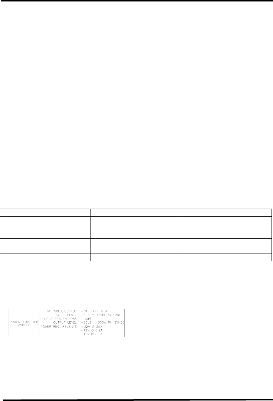
2.1.1 Power Amplifier Module
Assembly, 250Watt (1302868;
Appendix B)
The Power Amplifier Module Assembly is
made up of (A6) an Amplifier Control
Board (1301962), (A1) a UHF Phase/Gain
Board (1303213), (A2) a 150 Watt Driver
Pallet Assembly (1303293), (A3 & A4)
two RF Module Pallets, Philips (1300116),
and (A5) a 2-Way Combiner Board
(1303208).
The Power Amplifier Module contains
Broadband LDMOS amplifiers that cover
the entire UHF band with no tuning
required. Each module amplifies the RF
to a nominal 300W output power.
The Power Amplifier assembly is used to
amplify the RF output of the
Translator/Exciter Driver. A cable,
located on the rear chassis, connects the
RF output from the Exciter/Driver at J25

LX Series Power Amplifier Assembly Chapter 2, Amplifier Assembly Description
& Remote Control Connections
LX Series, Rev. 0 2-2
to J200 the RF input to the PA Assembly.
This module contains RF monitoring
circuitry for both an analog and a digital
system. Control and monitoring lines to
the Power Amplifier module are routed
through the floating blind-mate
connector of the Control &
Monitoring/Power Supply module.
The 100 Watt Translator/Exciter Driver
Power Amplifier module and any
External Amplifier modules contain the
same control and monitoring board.
This board monitors RF output power,
RF reflected power, the current draw of
amplifier sections, the supply voltage,
and the temperature of the PA heat sink.
The RF power detector circuit outputs
vary with operating frequency. These
circuits must be calibrated at their
intended operating frequency. Front
panel adjustment potentiometers are
used to calibrate the following:
Table 1: Power Amplifier Calibration
Adjustments in Analog Systems
R201 Reflected Power Cal
R202 Forward Power Cal
R204 Meter Offset Zero
In analog systems, the Aural power of
an Exciter Driver Power Amplifier and
the Aural power of any external
amplifier will not be reported by the
system Control Monitoring module.
Additionally the Visual power of these
amplifiers, is reported as Forward Power
just like in digital systems. In analog
systems, aural and visual power will only
be reported for the final system RF
output.
In digital systems, the Forward power of
an Exciter Driver Power Amplifier and
the Forward power of any external
amplifier, is reported by the system
Control Monitoring module.
If the Control Monitoring module is
monitoring a 5-50 Watt Digital or 10-
100 Watt Analog Translator, system
power is measured in the Power
Amplifier module. The wired
connections are transferred through the
power supply connector to the
backplane board on a five position
header. All four positions of control
board switch SW1 must be set on to
route these lines as the system's RF
power signals. In systems of output
power greater than 50 Watts digital or
100 Watts aural, system power is
monitored by an external module that is
connected to TB31 and control board
SW1 switches must be set off.
The Forward Power of the
Translator/Exciter Driver Power Amplifier
module is routed to the Upconverter
module as AGC #1. A system over-
drive condition is detected when this
value rises above 0.9 VDC. When an
over-drive condition is detected, the
Upconverter module reduces its RF
output level. For values less than 0.9
VDC, the Upconverter uses this voltage
for automatic gain.
LX Series Power Amplifier Assembly Chapter 2, Amplifier Assembly Description
& Remote Control Connections
LX Series, Rev. 0 2-3
Table 2-2. Power Amplifier Status Indicator
LED FUNCTION
ENABLED
(Green)
When lit Green, it indicates that the PA is in the Operate Mode. If a
Mute occurs, the PA will remain Enabled, until the input signal is
returned.
DC OK
(Green)
When lit Green, it indicates that the fuse protected DC inputs to the
PA module are OK.
TEMP
(Green)
When lit Green, it indicates that the temperature of the heatsink
assembly in the module is below 78˚C.
MOD OK
(Green)
When lit Green, it indicates that the PA Module is operating and has
no faults.
Table 2-3. Power Amplifier Control Adjustments
POTENTIOMETERS DESCRIPTION
RFL CAL Adjusts the gain of the Reflected Power monitoring circuit
VISUAL CAL Adjusts the gain of the Visual / Forward Power monitoring circuit
METER ZERO Adjusts the offset of the Forward Power monitoring circuit
Table 2-4. Power Amplifier Sample
DISPLAY FUNCTION
FWD SAMPLE RF sample of the amplified signal being sent out the module on J25.
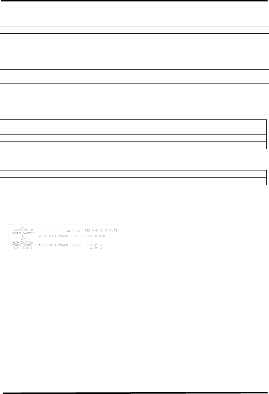
2.1.2 Power Supply Module
Assembly, 1kW LX Series (1302863;
Appendix B)
The Power Supply Module Assembly is
made up of (A1) a +32V/2000W
Switching Power Supply and (A2) a
±12V/40W Switching Power Supply.
The power supply module provides the
+32 VDC and the +12 VDC and –12 VDC
to the power amplifier module assembly.
2.1.3 Front Panel Display Screens
A 4 x 20 display located on the front of
the Control & Monitoring/Power Supply
Module is used in the LX Series
translator for control of the operation
and display of the operating parameters
of the entire translator.
2.2 System Operation
When the translator is in operate, as set
by the menu screen located on the
Control & Monitoring Module in the
exciter/driver assembly. The IF
Processor will be enabled, the mute
indicator on the front panel will be
extinguished. The +32 VDC stage of the
Power Supply in the Control & Monitoring
Module is enabled, the operate indicator
on the front panel is lit and the DC OK on
the front panel should also be green.
The enable and DC OK indicators on the
PA Module will also be green.
When the translator is in standby. The IF
Processor will be disabled, the mute
indicator on the front panel will be red.
The +32 VDC stage of the Power Supply
in the Control & Monitoring Module is
disabled, the operate indicator on the
front panel will be extinguished and the
DC OK on the front panel should remain
green. The enable indicator on the PA
Module is also extinguished.

LX Series Power Amplifier Assembly Chapter 2, Amplifier Assembly Description
& Remote Control Connections
LX Series, Rev. 0 2-4
If the translator does not switch to
Operate when the operate menu is
switched to Operate, check that all faults
are cleared and that the remote control
terminal block stand-by signal is not
active.
The translator can be controlled by the
presence of a modulated input signal. If
the input signal to the translator is lost,
the translator will automatically cutback
and the input fault indicator on the IF
Processor module will light. When the
video input signal returns, the translator
will automatically return to full power and
the input fault indicator will be
extinguished.
2.2.1 Principles of Operation
Operating Modes
This translator is either operating or in
standby mode. The sections below
discuss the characteristics of each of
these modes.
Operate Mode
Operate mode is the normal mode for
the translator when it is providing RF
power output. To provide RF power to
the output, the translator will not be in
mute. Mute is a special case of the
operate mode where the +32 VDC
section of the power supply is enabled
but there is no RF output power from
the translator. This condition is the
result of a fault condition that causes
the firmware to hold the IF Processor
module in a mute state.
Operate Mode with Mute Condition
The translator will remain in the operate
mode but will be placed in mute when
the following fault conditions exists in
the translator.
• Upconverter is unlocked
• Upconverter module is not present
• IF Processor module is not present
• Modulator (if present) is in
Aural/Visual Mute
Entering Operate Mode
Entering the operate mode can be
initiated a few different ways by the
translator control board. A list of the
actions that cause the operate mode to
be entered is given below:
• A low on the Remote Translator
Operate line.
• User selects "OPR" using switches
and menus of the front panel.
• Receipt of an “Operate CMD” over
the serial interface.
There are several fault or interlock
conditions that may exist in the
translator that will prevent the translator
from entering the operate mode. These
conditions are:
• Power Amplifier heat sink
temperature greater than 78˚C.
• Translator is Muted due to conditions
listed above.
• Power Amplifier Interlock is high
indicating that the amplifier is not
installed.
Standby Mode
The standby mode in the translator
indicates that the output amplifier of the
translator is disabled.
Entering Standby Mode
Similar to the operate mode, the
standby mode is entered using various
means. These are:
• A low on the Remote Translator
Stand-By line.
• Depressing the “STB” key on
selected front panel menus.
LX Series Power Amplifier Assembly Chapter 2, Amplifier Assembly Description
& Remote Control Connections
LX Series, Rev. 0 2-5
• Receipt of a “Standby CMD” over the
serial interface.
Operating Frequency
The LX Series translator controller is
designed to operate on UHF and VHF
frequencies. The exact output frequency
of the translator can be set to one of the
standard UHF frequencies, or it can be
set to a custom frequency using
software set-up menus. Since RF
performance of the translator requires
different hardware for different
frequency bands, not all frequency
configurations are valid for a specific
translator. The Power detectors in the
translator have frequency dependency,
therefore detectors of power amplifiers
are calibrated at their frequency of use.
The detectors for System RF monitoring
are also calibrated at the desired
frequency of use.
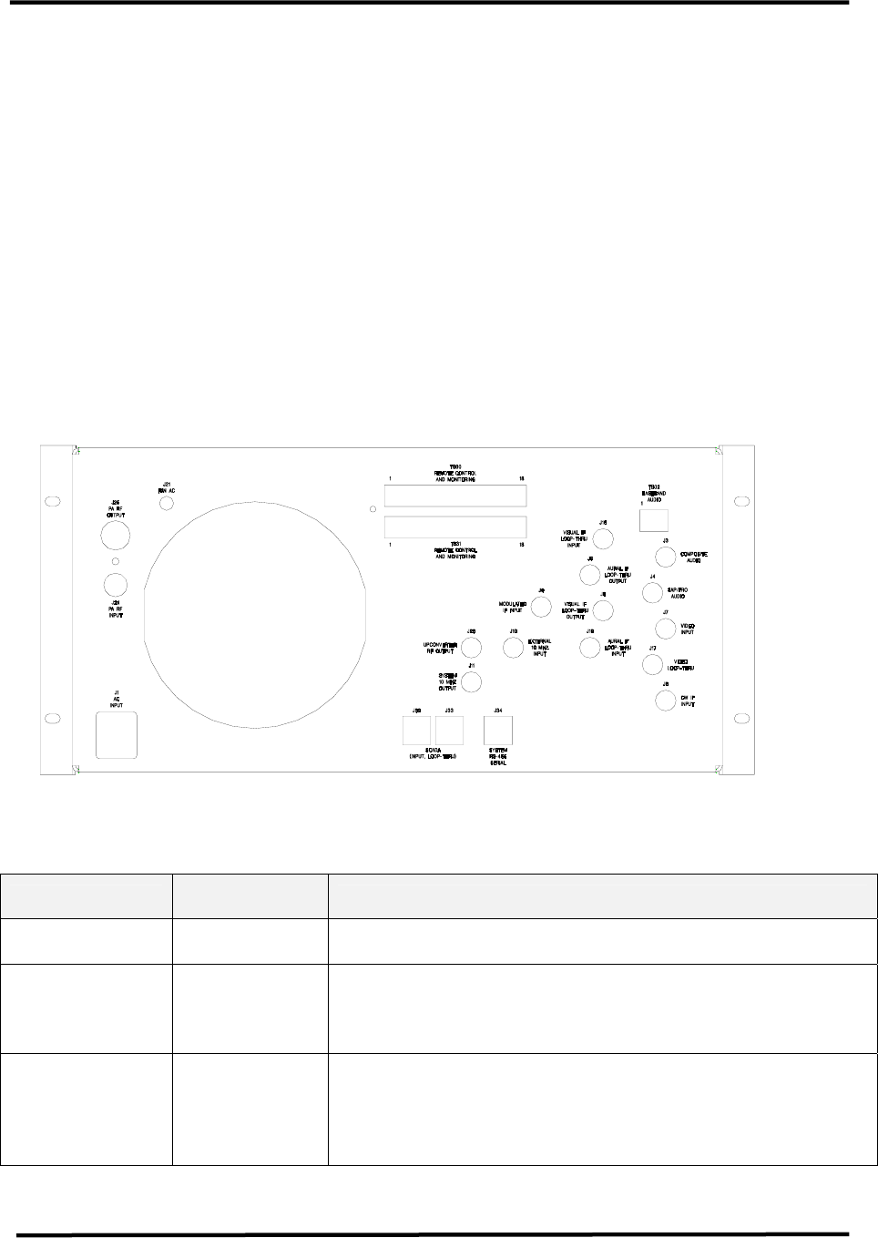
2.3 Customer Remote Connections
The remote monitoring and operation of
the translator is provided through
terminal blocks TB30 and TB31 located
on the rear of the chassis assembly. If
remote connections are made to the
translator, they must be made through
terminal blocks TB30 and TB31 at the
positions noted on the translator
interconnect drawing and Table 2-5.
Table 2-5: LX Series Chassis Assembly Hard Wired Remote Interface Connections to
TB30 or TB31, 18 pos. Terminal Blocks Located on the Rear of the Assembly
Signal Name Pin
Designations Signal Type/Description
RMT Translator
State TB30-1 Discrete Open Collector Output - A low indicates that the
translator is in the operate mode.
RMT Translator
Interlock TB30-2
Discrete Open Collector Output - A low indicated the
translator is OK or completes an interlock daisy chain.
When the translator is not faulted, the interlock circuit is
completed.
RMT Translator
Interlock
Isolated Return
TB30-3
Ground - Configurable ground return which can be either
jumpered directly to ground or it can be the “source” pin
of an FET so that the translator interlock can be daisy
chained with other translators. This signal does not
directly interface to the microcontroller.

LX Series Power Amplifier Assembly Chapter 2, Amplifier Assembly Description
& Remote Control Connections
LX Series, Rev. 0 2-6
Signal Name Pin
Designations Signal Type/Description
RMT AUX IO 1 TB30-4
RMT AUX IO 2 TB30-5
Discrete Open Collector Inputs, Discrete Open Drain
Outputs, or 0 - 5 VDC Analog Input - When used as an
output, this line is pulled to +5 VDC with a 1.0 kΩ
resistor for logic high and pulled to ground for a low. A
diode allows this line to be pulled up to 12 VDC. When
used as a digital input, this line considers all values over
2 Volts as high and those under 1 volt as low. As an
analog input, this line is protected by a 5.1 zener diode.
RMT
Translator
Operate
TB30-6
Discrete Open Collector Input - A pull down to ground on
this line indicates that the translator is to be placed into
the operate mode.
RMT
Translator
Stand-By
TB30-7
Discrete Open Collector Input - A pull down to ground on
this line indicates that the translator is to be placed into
the standby mode.
RMT Power
Raise TB30-8
Discrete Open Collector Input - A pull down to ground on
this line indicates that the translator power is to be
raised.
RMT Power
Lower TB30-9
Discrete Open Collector Input - A pull down to ground on
this line indicates that the translator power is to be
lowered.
RMT
System Reflect
Power
TB30-10
Analog Output - 0 to 4.0 V- This is a buffered loop
through of the calibrated “System Reflected Power ” and
indicates the translator's reflected output power. The
scale factor is 25%/3.2V.
RMT System
Visual/Forward
Power
TB30-11
Analog Output - 0 to 4.0 V- This is a buffered loop
through of the calibrated “System Visual/Avg. Power ”.
Indicates the translator's Visual / Average power. Scale
factor is 100%/3.2V.
RMT
System Aural
Power
TB30-12
Analog Output - 0 to 4.0 V- This is a buffered loop
through of the calibrated “System Aural Power ”.
Indicates the translator's forward Aural output power.
The scale factor is 100%/3.2V.
RMT Spare 1 TB30-13 Remote connection to spare module - Use is TBD.
RMT Spare 2 TB30-14 Remote connection to spare module - Use is TBD.
System Reflect
Power TB31-13
Analog Input - 0 to 1.00 V- This is the input of the
“System Reflected Power ” indicating the translator's
reflected output power. The scale factor is 25%/0.80V.
System Visual /
Forward Power TB31-14
Analog Input - 0 to 1.00 V- This is the input of the
“System Visual / Forward Power ” indicating the
translator's forward Visual / Forward output power. The
scale factor is 100%/0.80V.
System Aural
Power TB31-15
Analog Input - 0 to 1.00 V- This is the input of the
“System Aural Power ” indicating the translator's forward
Aural output power. The scale factor is 100%/0.80V.
IF Processor
IF Signal Select TB31-3
Discrete Open Collector Input - A low indicates that the
modulator IF source is to be used by the IF Processor
module. When floating an analog IP Processor module
may use the Modulated IF Input if the IF Processor sled
is so configured.
IF Processor TB31-4 Analog Output - 0 to 5.00 V- This is the input of IF

LX Series Power Amplifier Assembly Chapter 2, Amplifier Assembly Description
& Remote Control Connections
LX Series, Rev. 0 2-7
Signal Name Pin
Designations Signal Type/Description
DLC Voltage Processor module for digital system RF output power
control.
UC AGC #2
Voltage TB31-5
Auxiliary Analog Input - 0 to 1V- This voltage is used by
the Upconverter for gain control. Linear signal with
display resolution of 0.01 %. Primary signal source is
J34-1.
RMT Ground TB30-15, and
17 Ground pins available through Remote
RMT Ground TB31-1, 2, 6
to 12, and 17 Ground pins available through Remote
RMT +12 VDC TB30-16
TB31-16
+12 VDC available through Remote w/ 2 Amp re-settable
fuse
RMT -12 VDC TB30-18
TB31-18
-12 VDC available through Remote w/ 2 Amp re-settable
fuse