UBS Axcera LU500AL 500-Watt UHF Translator User Manual 382698
UBS-Axcera 500-Watt UHF Translator 382698
Contents
- 1. Section 5 Users Manual Page
- 2. Title Page External Amplifier
- 3. Table of Contents External Amplifier
- 4. Chapter 1 External Amplifier
- 5. Chapter 2 External Amplifier
- 6. Chapter 3 External Amplifier
- 7. Chapter 4 External Amplifier
- 8. Chapter 5 External Amplifier
- 9. Appendix Pages External Amplifier
- 10. Drawings List External Amplifier
- 11. Title Page Exciter
- 12. Table of Contents Exciter
- 13. Chapter 1 Exciter
- 14. Chapter 2 Exciter
- 15. Chapter 3 Exciter
- 16. Chapter 4 Exciter
- 17. Chapter 5 Exciter
- 18. Appendix Pages Exciter
- 19. Drawings List Exciter
- 20. Data Sheet Exciter and Amplifier
Chapter 3 Exciter

Analog UHF Driver/Translator Chapter 3, Site Considerations,
Installation and Setup Procedures
LX Series, Rev. 0 3-1
Chapter 3
Site Considerations, Installation and Setup Procedures
There are special considerations that
need to be taken into account before the
Innovator LX Series translator can be
installed. For example, if the installation
is completed during cool weather, a heat-
related problem may not surface for
many months, suddenly appearing during
the heat of summer. This section
provides planning information for the
installation and set up of the translator.
3.1 Site Considerations
The translator requires an AC input line
of 117 VAC @ 5 amps for the 10W
translator or 117 VAC @ 10 amps for the
100W Translator.
The Innovator LX Series Translators are
designed and built to provide long life
with a minimum of maintenance. The
environment in which they are placed is
important and certain precautions must
be taken. The three greatest dangers to
the translator are heat, dirt, and
moisture. Heat is usually the greatest
problem, followed by dirt, and then
moisture. Over-temperature can cause
heat-related problems such as thermal
runaway and component failure. Each
amplifier module in the translator
contains a thermal interlock protection
circuit that will shut down that module
until the temperature drops to an
acceptable level.
A suitable environment for the translator
can enhance the overall performance and
reliability of the translator and maximize
revenues by minimizing downtime. A
properly designed facility will have an
adequate supply of cool, clean air, free of
airborne particulates of any kind, and no
excessive humidity. An ideal environment
will require temperature in the range of
40° F to 70° F throughout the year,
reasonably low humidity, and a dust-free
room. It should be noted that this is
rarely if ever attainable in the real world.
However, the closer the environment is
to this design, the greater the operating
capacity of the translator.
The fans are designed and built into the
translator will remove the heat from
within the modules, but additional means
are required for removing this heat from
the building. To achieve this, a few issues
need to be resolved. The first step is to
determine the amount of heat to be
removed from the translator room. There
are generally three sources of heat that
must be considered. The first and most
obvious is the heat from the translator
itself. This amount can be determined for
a 100W translator by subtracting the
average power to the antenna (69.5
watts) from the AC input power (675
watts) and taking this number in watts
(605.5) and then multiplying it by 3.41.
This gives a result of 2,065, the BTUs to
be removed every hour. 12,000 BTUs per
hour equals one ton. Therefore, a 1/4-
ton air conditioner will cool a 100W
translator.
The second source of heat is other
equipment in the same room. This
number is calculated in the same way as
the equation for BTUs. The third source
of heat is equally obvious but not as
simple to calculate. This is the heat
coming through the walls, roof, and
windows on a hot summer day. Unless
the underside is exposed, the floor is
usually not a problem. Determining this
number is usually best left up to a
qualified HVAC technician. There are far
too many variables to even estimate this
number without reviewing the detailed
drawings of the site that show all of the
construction details. The sum of these
three sources is the bulk of the heat that
must be removed. There may be other
sources of heat, such as personnel, and
all should be taken into account.

Analog UHF Driver/Translator Chapter 3, Site Considerations,
Installation and Setup Procedures
LX Series, Rev. 0 3-2
Now that the amount of heat that must
be removed is known, the next step is to
determine how to accomplish this. The
options are air conditioning, ventilation,
or a combination of the two. Air
conditioning is always the preferred
method and is the only way to create
anything close to an ideal environment.
Ventilation will work quite well if the
ambient air temperature is below 100° F,
or about 38° C, and the humidity is kept
at a reasonable level. In addition, the air
stream must be adequately filtered to
ensure that no airborne particulates of
any kind will be carried into the
translator. The combination of air
conditioning for summer and ventilation
during the cooler months is acceptable
when the proper cooling cannot be
obtained through the use of ventilation
alone and using air conditioning
throughout the year is not feasible.
Caution: The use of air conditioning
and ventilation simultaneously is not
recommended. This can cause
condensation in the translators.
The following precautions should be
observed regarding air conditioning
systems:
1. Air conditioners have an ARI
nominal cooling capacity rating. In
selecting an air conditioner, do not
assume that this number can be
equated to the requirements of
the site. Make certain that the
contractor uses the actual
conditions that are to be
maintained at the site in
determining the size of the air
conditioning unit. With the desired
conditioned room temperature
under 80° F, the unit must be
derated, possibly by a substantial
amount.
2. Do not have the air conditioner
blowing directly onto the
translator. Under certain
conditions, condensation may
occur on, or worse in, the
translator.
3. Do not separate the front of the
translator from the back with the
thought of air conditioning only
the front of the unit. Cooling air is
drawn in at the front of all
translators and in the front and
back of others. Any attempt to
separate the front of the translator
from the rear of the unit will
adversely affect the flow of cooling
air.
4. Interlocking the translator with the
air conditioner is recommended to
keep the translator from operating
without the necessary cooling.
5. The periodic cleaning of all filters
is a must.
When using ventilation alone, the
following general statements apply:
1. The blower, with attendant filters,
should be on the inlet, thereby
pressurizing the room and
preventing dirt from entering the
translator.
2. The inlet and outlet vents should
be on the same side of the
building, preferably the leeward
side. As a result, the pressure
differential created by wind will be
minimized. Only the outlet vent
may be released through the roof.
3. The inlet and outlet vents should
be screened with 1/8-inch
hardware cloth (preferred) or
galvanized hardware cloth
(acceptable).
4. Cooling air should enter the room
as low as practical but in no case
higher than four feet above the
floor. The inlet must be located
where dirt, leaves, snow, etc., will
not be carried in with the cooling
air.

Analog UHF Driver/Translator Chapter 3, Site Considerations,
Installation and Setup Procedures
LX Series, Rev. 0 3-3
5. The exhaust should be located as
high as possible. Some ducting is
usually required to insure the
complete flushing of heated air
with no stagnant areas.
6. The filter area must be large
enough to insure a maximum air
velocity of 300 feet per minute
through the filter. This is not a
conservative number but a never-
exceed number. In a dusty or
remote location, this number
should be reduced to 150 CFM.
7. The inlet and outlet(s) must have
automatic dampers that close any
time the ventilation blower is off.
8. In those cases in which translators
are regularly off for a portion of
each day, a temperature-
differential sensor that controls a
small heater must be installed.
This sensor will monitor inside and
outside temperatures
simultaneously. If the inside
temperature falls to within 5° F of
the outside temperature, the
heater will come on. This will
prevent condensation when the
ventilation blower comes on and
should be used even in the
summer.
9. A controlled-air bypass system
must be installed to prevent the
temperature in the room from
falling below 40° F during
translator operation.
10. The blower should have two
speeds, which are thermostatically
controlled, and be interlocked with
the translator.
11. The blower on high speed must be
capable of moving the required
volume of air into a half inch of
water pressure at the required
elevation. The free air delivery
method must not be used.
12. Regular maintenance of the filters,
if used, can not be
overemphasized.
13. Above 4000 feet, for external
venting, the air vent on the
cabinet top must be increased to
an 8-inch diameter for a 1-kW
translator and to a 10-inch
diameter for 5-kW and 6-kW
translators. An equivalent
rectangular duct may be used but,
in all cases, the outlet must be
increased by 50% through the
outlet screen.
14. It is recommended that a site plan
be submitted to Axcera for
comments before installation
begins.
In calculating the blower requirements,
filter size, and exhaust size, if the total
load is known in watts, 2000 CFM into ½
inch of water will be required for each
5000 watts. If the load is known in BTUs,
2000 CFM into ½ inch of water will be
required for each 17,000 BTUs. The inlet
filter must be a minimum of seven
square feet, larger for dusty and remote
locations, for each 5000 watts or 17,000
BTUs. The exhaust must be at least four
square feet at the exhaust screen for
each 5000 watts or 17,000 BTUs.
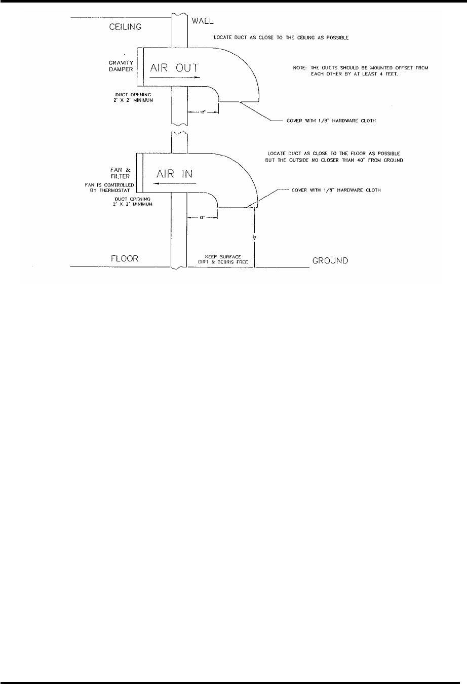
The information presented in this section
is intended to serve only as a general
guide and may need to be modified for
unusually severe conditions. A
combination of air conditioning and
ventilation should not be difficult to
design (see Figure 3-1).
System interlocking and thermostat
settings should be reviewed with Axcera.
As with any equipment installation, it is
always good practice to consult the
manufacturer when questions arise.
Axcera can be contacted at (724) 873-
8100
Analog UHF Driver/Translator Chapter 3, Site Considerations,
Installation and Setup Procedures
LX Series, Rev. 0 3-4
Figure 3-1. 1 kW Minimum Ventilation Configuration
3.2 Unpacking the Chassis
w/modules, receiver tray, trap filter
and band-pass filter assembly
Thoroughly inspect the chassis with
modules and all other materials upon
their arrival. Axcera certifies that upon
leaving our facility the equipment was
undamaged and in proper working order.
The shipping containers should be
inspected for obvious damage that
indicates rough handling.
Remove the chassis and modules, along
with the receiver tray, the trap filter and
band-pass filter, from the crates and
boxes.
Check for dents and scratches or broken
connectors, switches, display, or
connectors. Any claims against in-transit
damage should be directed to the carrier.
Inform Axcera as to the extent of any
damage as soon as possible.
The modules are mounted to the chassis
assembly with slides that are on the top
and the bottom of the modules. There
are two thumb screws on the front panel
that hold each of the modules in place.
The receiver tray is mounted in the cabinet
using Chassis Trak cabinet slides. The tray
slides are on the side of the tray. Inspect
the tray for any loose hardware or
connectors, tightening where needed
3.3 Installing the Chassis w/modules,
receiver tray, trap filter and band-
pass filter assembly
The chassis assembly and receiver tray are
made to mount in a standard 19” rack. The
chassis assembly mounts using the four
#10 clearance mounting holes on the ends.
The chassis should be positioned; to
provide adequate air intake into the front
and the air exhaust of the fan in the rear;
the ability to slide the modules out for
replacement purposes; the installation of
the trap filter; the band-pass filter
assembly; and output transmission line.
The chassis or cabinet in which it is
mounted should be grounded using copper
strapping material.
Analog UHF Driver/Translator Chapter 3, Site Considerations,
Installation and Setup Procedures
LX Series, Rev. 0 3-5
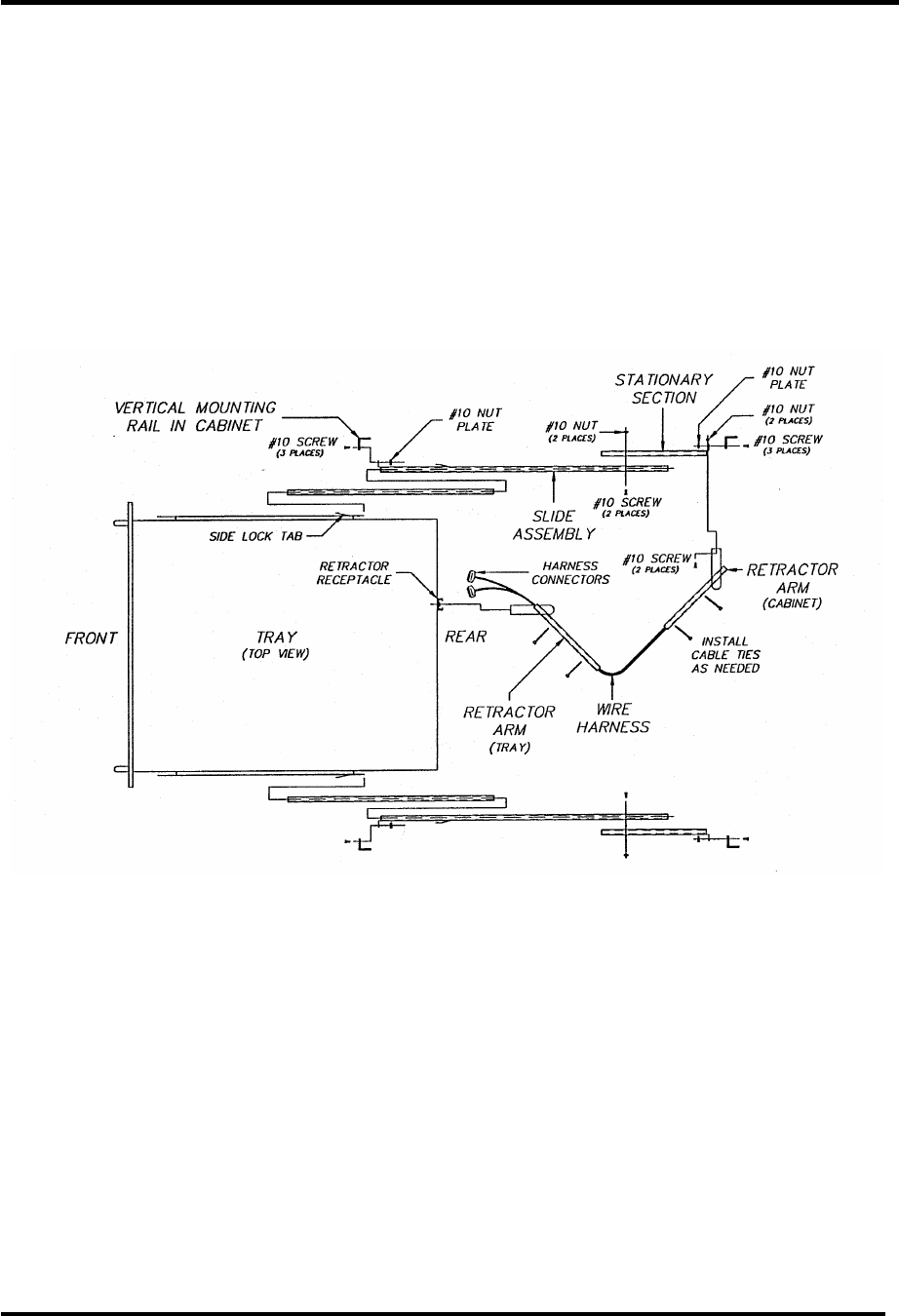
Normally, the receiver tray mounts below
the Chassis assembly using Chassis Trak
cabinet slides. The Side Rails are pre-
mounted on the sides of the Tray. Install
the Tray slides found in the Installation
Material into the left and right side of the
standard 19" Cabinet. Refer to the
"Cabinet Mounting Instructions For Tray
Slides" drawing below. Check that the
Tray Slides are mounted in line with each
other. Secure the slides by connecting
them to the front and rear mounting bars
using the No. 10 bolts and bar nuts
provided. Insert the Tray onto the Tray
Slides and slide the Tray into the cabinet.
Slowly slide the Tray in and out to verify
that it does not rub against the Chassis
assembly and has no restriction to free
movement. Adjustment to the position of
the Tray may be necessary, and is
accomplished by loosening the cabinet
slide mounting bolts that hold the front of
the slide to the mounting frame of the
Cabinet and moving the Tray up or down
as needed to correct for the rubbing.
Retighten after adjusting.
Figure 3-2. Tray Slides Cabinet Mounting Diagram
NOTE: To pull out the power amplifier
module for replacement purposes, the
input and output coaxial cables must first
be removed from the rear of the chassis
assembly.
Connect the digital mask filter and
coupler assembly to the output of the
chassis assembly.
Analog UHF Driver/Translator Chapter 3, Site Considerations,
Installation and Setup Procedures
LX Series, Rev. 0 3-6
Figure 3-3. Front and Rear View Reconnection Drawing
Connect the transmission line for the
antenna system to the band-pass filter
output.
3.4 AC Input
The Exciter/Amplifier chassis assembly
needs to be plugged into an AC outlet
of 115 or 230 VAC, as set at the
factory. Current requirements are 5
amps for 10W translators and 10 amps
50W translators, in order to operate.
The Receiver Tray requires an AC outlet
of 115 VAC or 230 VAC. The AC can be
set for the Receiver Tray as follows.
FOR 115 VAC – Verify that 115 volts
is indicated on the rear panel cover of
the power entry module. If not, gently
open the cover, remove the fuse
assembly, and reinsert the assembly so
that 115 volts is visible with the cover
closed.
FOR 230 VAC – Verify that 230 volts
is indicated on the rear panel cover of
the power entry module. If not, gently
open the cover, remove the fuse
assembly, and reinsert the assembly so
that 230 volts is visible with the cover
closed.
When the AC power cord for the
exciter/amplifier chassis is plugged in,
the AC is always connected to the
translator. There is an On/off circuit
breaker located on the rear of the
Receiver Tray that needs to be
switched on to apply the AC to the rest
of the Tray.
This completes the unpacking and
installation of the Innovator LX Series
UHF television translator. Refer to the
setup and operation procedures that
follow before applying power to the
translator.
3.5 Setup and Operation
Initially, the translator should be turned
on with the RF output at the coupler
assembly terminated into a dummy
load of 10W or 100W depending on the
power rating of the translator. If a load
is not available, check that the output
of the coupler assembly is connected to
the antenna for your system.
Analog UHF Driver/Translator Chapter 3, Site Considerations,
Installation and Setup Procedures
LX Series, Rev. 0 3-7
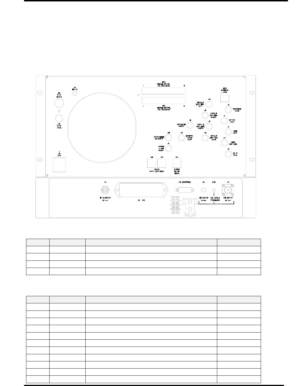
3.5.1 Input Connections
The input connections to the translator
are to the rear of the Receiver Tray and
to the rear of the Chassis Assembly for
the translator.
Refer to the tables and description that
follows for detailed information.
Figure 3-4: Rear View of Innovator LX Series Driver/Translator
Table 3-1: Rear Chassis Connections for the Receiver Tray.
Port TYPE Function Ohm
J1 N RF Input 50
J2 IEC AC Input N/A
J3 15-pin D Remote Connections N/A
J4 BNC IF Output 50
Table 3-2: Rear Chassis Connections for the Innovator LX Series Driver/Translator.
Port Type Function Ohm
J1 IEC AC Input N/A
TB02 Term Base Band Audio Input 600
J3 BNC Composite Audio Input 75
J4 BNC SAP / PRO Audio Input 50
J5 BNC CW IF Input 50
J6 BNC Modulated IF Input 50
J7 BNC Video Input (Isolated) 75
J8 BNC Visual IF Loop-Thru Output 50
J9 BNC Aural IF Loop-Thru Output 50
J10 BNC 10 MHz Reference Input 50
J11 BNC 10 MHz Reference Output 50

Analog UHF Driver/Translator Chapter 3, Site Considerations,
Installation and Setup Procedures
LX Series, Rev. 0 3-8
Port Type Function Ohm
J17 BNC Video Loop-Thru (Isolated) 75
J18 BNC Visual IF Loop-Thru Input 50
J19 BNC Aural IF Loop-Thru Input 50
J23 BNC Upconverter RF Output 50
J24 BNC Power Amplifier RF Input 50
J25 N Power Amplifier RF Output 50
TB30 Term Remote Control & Monitoring
TB31 Term Remote Control & Monitoring
J32 RJ-45 SCADA (Input / Loop-Thru) CAT5
J33 RJ-45 SCADA (Input / Loop-Thru) CAT5
J34 RJ-45 System RS-485 Serial CAT5
Analog UHF Driver/Translator Chapter 3, Site Considerations,
Installation and Setup Procedures
LX Series, Rev. 0 3-9
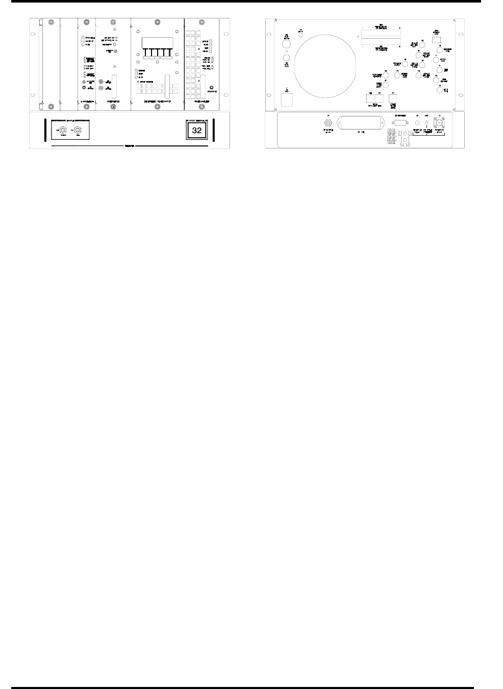
3.5.2 Front Panel Screens for the
Exciter/Amplifier Chassis Assembly
A 4 x 20 display located on the front of
the Control & Monitoring/Power Supply
Module is used in the Innovator LX
translator for control of the operation
and display of the operating parameters
of the translator. Below are the display
screens for the system. The ↑ and ↓
characters are special characters used to
navigate up or down through the menu
screens. Display text flashes on discrete
fault conditions for all screens that
display a fault condition.
When the translator is in operate mode,
the STB menu appears. When the
translator is in standby mode, the OPR
menu appears.
Display Menu Screens for the Innovator LX Series Translator
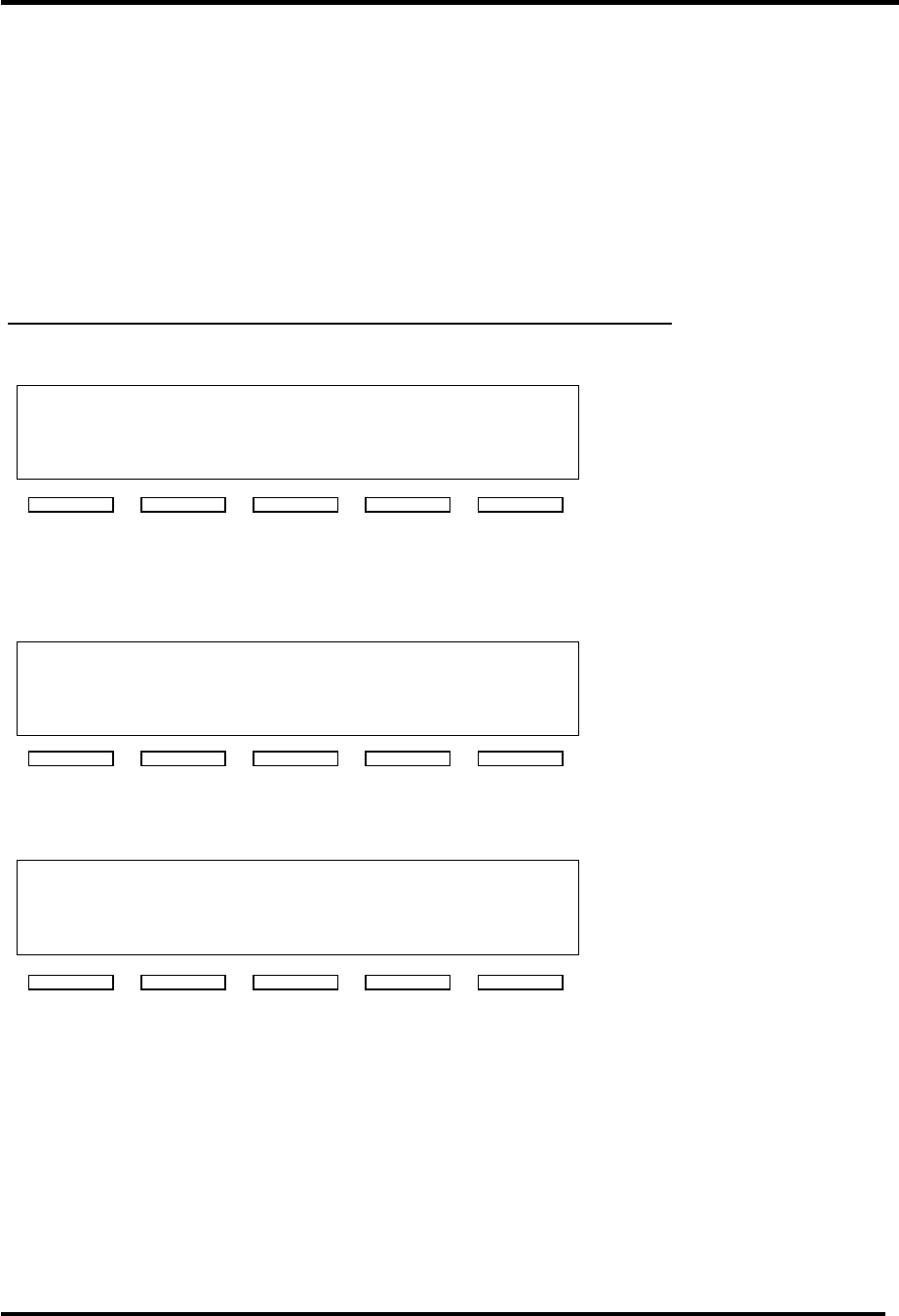
Table 3-3: Menu 01 - Splash Screen #1
A X C E R A
1 0 3 F R E E D O M D R I V E
L A W
R E N C E , P A . 1 5 0 5 5
( 7 2 4 ) 8 7 3 - 8 1 0 0
This is the first of the two translator splash screens that is shown for the first few
seconds after reset.
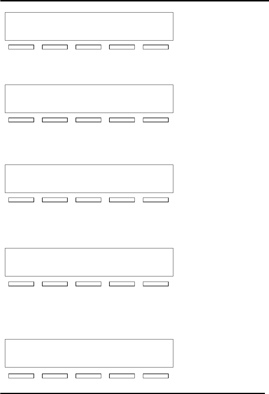
Table 3-4: Menu 02- Splash Screen #2
I N N O V A TO R L U 0 5 0 0 A L
C O D E V E R S I O N 1 . 0
F I R M W A R E 1 3 0 2 1 6 4
S C A D A A D D R E S S 5
This is the second of the two translator splash screens
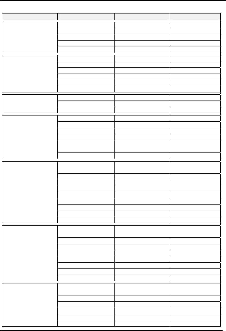
Table 3-5: Menu 10 - Main Screen
F O R W A R D P W R 1 0 0 %
R E F L E C T E D P W R 1 . 0 %
↑
↓ S T B
This is the default main screen of the translator. When the translator is in operate, the
'STB' characters appear allowing an operator to place the translator in stand-by. When
the translator is in standby the 'STB' characters are replaced with 'OPR' and an operator
can place the translator into operate by pressing the right most switch on the front panel
display. If the ↓ key is activated the system changes to Menu 11. If the ↑ key is
activated the system displays to Menu 13.
Analog UHF Driver/Translator Chapter 3, Site Considerations,
Installation and Setup Procedures
LX Series, Rev. 0 3-10
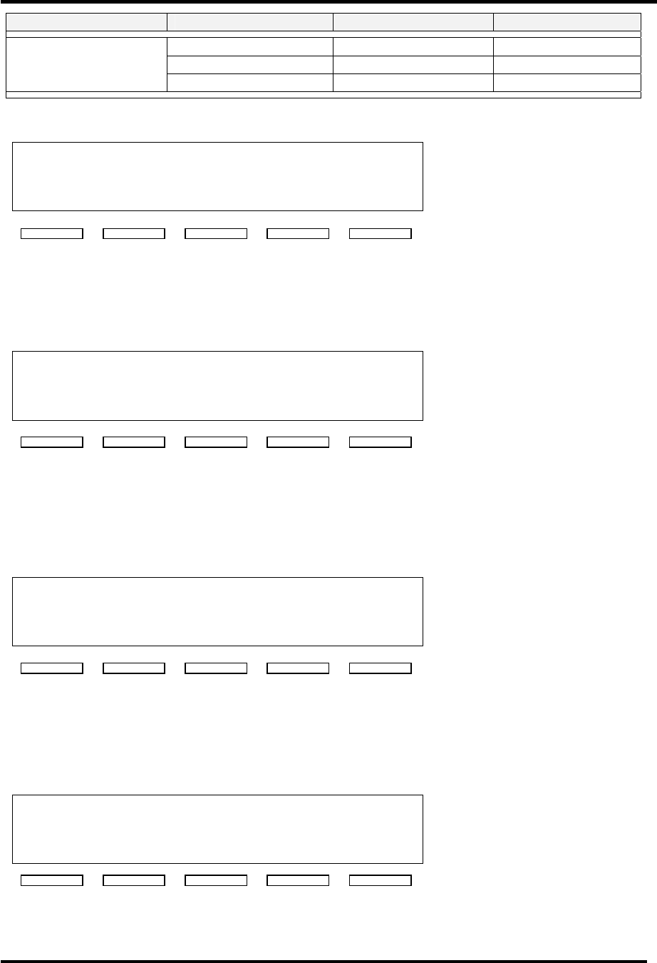
Table 3-6: Menu 11 - Error List Access Screen
S Y S T E M E R R O R S
6
E R R O R L I S T D I S P L A Y
↑
↓ E N T S T B
This screen of the translator shows the current number of errors and provides operator
access to view the error list. This is the entry point to Menu 20. If the ↓ key is activated
the system changes to Menu 12. If the ↑ key is activated the system returns to Menu 10.
Table 3-7: Menu 12 - Translator Device Data Access Screen
T R A N S M I T T E R D E T A I L S
↑
↓ E N T S T B
This screen of the translator allows access to various parameters of the translator
system. This is the entry point to Menu 30. If the ↓ key is activated the system changes
to Menu 13. If the ↑ key is activated the system returns to Menu 11.
Table 3-8: Menu 13 - Translator Configuration Access Screen
T R A N S M I T T E R S E T - U P
↑
↓ E N T S T B
This screen of the translator allows access to various software setting of the translator
system. This is the entry point to Menu 40. If the ↓ key is activated the system returns
to Menu 10. If the ↑ key is activated the system returns to Menu 12.
Table 3-9: Menu 20 - Error List Display Screen
S Y S T E M E R R O R S 1 / 6
U P C O N V E R T E R M O D U L E
I N T E R L O C K F A U L T
↑
↓ C L R E S C
This screen of the translator allows access to system faults. Fault logging is stored in
non-volatile memory. The translator's operating state can not be changed in this screen.
The 'CLR' switch is used to clear previously detected faults that are no longer active. The
↑ key and ↓ key allow an operator to scroll through the list. The ESC switch is used to
leave this screen.
Table 3-10: Menu 30 - Translator Device Details Screen
S Y S T E M D E T A I L S
X M T R I N O P E R A T E M O D E
P O W E R S U P P L Y : O K
↑
↓
←
→
E S C

Analog UHF Driver/Translator Chapter 3, Site Considerations,
Installation and Setup Procedures
LX Series, Rev. 0 3-11
This screen of the translator allows access to translator parameters of installed devices.
The system must be configured for the translator to know which devices are expected to
be present. Current values for all installed devices are shown. If a module is not
installed, only a "MODULE NOT PRESENT" message will be presented. The ↑ and ↓ arrows
scroll through the different parameters of each device.
Analog UHF Driver/Translator Chapter 3, Site Considerations,
Installation and Setup Procedures
LX Series, Rev. 0 3-12
Table 3-11: Translator Device Parameters
System Component Parameter Normal Faulted (Blinking)
PLL CIRCUIT LOCKED UNLOCKED
OUTPUT LEVEL 0 - 200 IRE N/A
AURAL DEVIATION 0 - 125 kHz N/A
CW INPUT PRESENT NOT USED Modulator
(Analog Systems) STATION ID SEND soft key N/A
INPUT STATE OK FAULT
MODULATION OK FAULT
IF INPUT MODULATOR or J6 N/A
ALC LEVEL 0 - 5.00 V N/A
ALC MODE AUTO or MANUAL N/A
IF Processor
(Analog Systems) DLC LEVEL 0 - 5.00 V N/A
ALC LEVEL 0 - 5.00 V N/A
ALC MODE AUTO or MANUAL N/A IF Processor
(Digital Systems) DLC LEVEL 0 - 5.00 V N/A
PLL CIRCUIT LOCKED FAULT
AFC LEVEL 0 - 5.00 V N/A
AGC 1 LEVEL 0 - 5.00 V N/A
AGC 2 LEVEL 0 - 5.00 V N/A
EX. 10 MHz
PRESENT or NOT
USED N/A
LO / Upconverter LO FREQ xxx.xxx MHz N/A
AMP STATE
ENABLED or
DISABLED N/A
SUPPLY VOLTAGE OK or OFF FAULT
VISUAL POWER xxx% xxx%
AURAL POWER xxx% xxx%
REFLECTED POWER xxx% xxx%
AMP CURRENT 1 xx.xA xx.xA
AMP CURRENT 2 xx.xA xx.xA
AMP TEMPERATURE xxC xxC
Power Amp
(In Analog
Systems) CODE VERSION x.x N/A
AMP STATE
ENABLED or
DISABLED N/A
SUPPLY VOLTAGE OK or OFF FAULT
FORWARD POWER xxx% xxx%
REFLECTED POWER xxx% xxx%
AMP CURRENT 1 xx.xA xx.xA
AMP CURRENT 2 xx.xA xx.xA
AMP TEMPERATURE xxC xxC Power Amp
(In Digital Systems) CODE VERSION x.x N/A
AMP STATE
ENABLED or
DISABLED N/A
SUPPLY VOLTAGE OK or OFF FAULT
FORWARD POWER xxx% xxx%
REFLECTED POWER xxx% xxx%
AMP CURRENT 1 xx.xA xx.xA
Ext. Power Supply
Tray x Mod y
AMP CURRENT 2 xx.xA xx.xA
Analog UHF Driver/Translator Chapter 3, Site Considerations,
Installation and Setup Procedures
LX Series, Rev. 0 3-13
System Component Parameter Normal Faulted (Blinking)
AMP CURRENT 3 xx.xA xx.xA
AMP TEMPERATURE xxC xxC
CODE VERSION x.x N/A
Table 3-12: Menu 40 - Translator Set-up: Power Raise/Lower Screen
T R A N S M I T T E R S E T - U P
0 1 P O W E R R A I S E / L O W E R
S E T T I N G 1 0 0 %
↑
↓ ( + ) E S C ( - )
This screen of the translator is the first of several that allows access to translator set-up
parameters. When + is selected, the Power will increase. When - is selected, the Power
will decrease..
Table 3-13: Menu 40-1 - Translator Set-up: Model Select Screen
T R A N S M I T T E R S E T - U P
0 2 T R A N S M I T T E R M O D E L
N U M B E R L U 0 1 0 0 A L
↑
↓ ( + ) E S C ( - )
This screen is used to specify which components are expected to be part of the system.
By specifying the model number, the translator control firmware knows which
components should be installed and it will be able to display faults for components that
are not properly responding to system commands.
Table 3-14: Menu 40-2 - Translator Set-up: Frequency Select Screen
T R A N S M I T T E R S E T - U P
0 2
F R E Q U E N C Y S E L E C T
T A B L E O R C U S T O M
↑
↓ ( + ) E S C ( - )
This screen of the translator is allows access to translator frequency set-up parameters.
The choices of this screen are 'TABLE' or 'CUSTOM'. When table is selected, the next
menu will be used to select the desired operating frequency. When custom is selected,
the next menu is used to select a specific operating frequency.
Table 3-15: Menu 40-3 - Translator Set-up: Frequency Table Select Screen
T R A N S M I T T E R S E T - U P
0 3 F R E Q U E N C Y S E L E C T
C H 2 0 5 0 6 - 5 1 2 M H z
↑
↓ ( + ) E S C ( - )
The choices of this screen are from the standard UHF / VHF tables. + and - change the
desired value of the translator. Any change to frequency is immediately set to the LO /
Upconverter Frequency Synthesizer PLL circuit.
Analog UHF Driver/Translator Chapter 3, Site Considerations,
Installation and Setup Procedures
LX Series, Rev. 0 3-14
Table 3-16: Menu 40-4 - Translator Set-up: IF Frequency Screen
T R A N S M I T T E R S E T - U P
0 3 I F F R E Q U E N C Y
I N P U T 4 5 . 7 5 M H z
↑
↓ ( + ) E S C >
This screen is used to specify the IF Input frequency. This value plus the desired channel
value is used to calculated the desired LO frequency. + is used to increase the selected
value from 0 to 9. The > key is used to select from each of the different fields that make
up the desired frequency. Any change to frequency is immediately set to the LO /
Upconverter Frequency Synthesizer PLL circuit.
Table 3-17: Menu 40-5 - Translator Set-up: Custom Frequency Select Screen
T R A N S M I T T E R S E T - U P
0 3 F R E Q U E N C Y S E L E C T
0 5 0 7 . 2 5 0
M H z
↑
↓ ( + ) E S C ( - )
This screen is used to specify the operating frequency to an exact value. + is used to
increase the selected value from 0 to 9. The > key is used to select from each of the
different fields that make up the desired frequency. Any change to frequency is
immediately set to the LO / Upconverter Frequency Synthesizer PLL circuit.
Table 3-18: Menu 40-6 - Translator Set-up: Serial Address Screen
T R A N S M I T T E R S E T - U P
0 4 S E R I A L A D D R E S S 5
↑
↓ ( + ) E S C ( - )
This screen allows the user to set the serial address of the translator. The default
address is 5. This value and all other set-up parameters, are stored in non-volatile
memory.
Table 3-19: Menu 40-7 - Translator Set-up: System Forward Power Calibration
T R A N S M I T T E R S E T - U P
0 6 S Y S T E M C A L I B R A T E
F O R W A R D P W R 1 0 0 %
↑
↓ ( + ) E S C ( - )
This screen is used to adjust the calibration of the system's forward power. A symbol
placed under the '6' character is used to show minor changes in the calibration value.
When the calibration value is at full value, the character will be full black. As the value
decreases, the character pixels are gradually turned off.
Analog UHF Driver/Translator Chapter 3, Site Considerations,
Installation and Setup Procedures
LX Series, Rev. 0 3-15
Table 3-20: Menu 40-8 - Translator Set-up: System Aural Power Calibration
T R A N S M I T T E R S E T - U P
0 6
S Y S T E M C A L I B R A T E
A U R A L P W R 1 0 0 %
↑
↓ ( + ) E S C ( - )
In analog systems, this screen is used to adjust the calibration of the system's aural
forward power.
Table 3-21: Menu 40-9 - Translator Set-up: System Reflected Power Calibration
T R A N S M I T T E R S E T - U P
0 6 S Y S T E M C A L I B R A T E
R E F L E C T P W R X X X %
↑
↓ ( + ) E S C ( - )
This screen is used to adjust the calibration of the system's reflected power.
Table 3-22: Menu 40-10 - Translator Set-up: Forward Power Fault Threshold Screen
T R A N S M I T T E R S E T - U P
0 7 M I N I M U M F O R W A R D
P O WE R F A U L T 5 0 %
↑
↓ ( + ) E S C ( - )
This screen is used to set the minimum forward power fault threshold. When the
translator is operating, it must operate above this value otherwise the system will shut
down with fault for 5 minutes. If after five minutes the fault is not fixed, the translator
will enable, measure power less than this value and again shut down for five minutes.
Table 3-23: Menu 40-11 - Translator Set-up: Reflected Power Fault Threshold
T R A N S M I T T E R S E T - U P
0 8 M A X I M U M R E F L E C T E D
P O WE R F A U L T 1 0 %
↑
↓ ( + ) E S C ( - )
This screen is used to set the maximum reflected power fault threshold. When the
translator is operating, it must not operate above this value otherwise the system will
shut down with fault for 5 minutes. If after five minutes the fault is not fixed, the
translator will enable, measure power above this value and again shut down for five
minutes.

Analog UHF Driver/Translator Chapter 3, Site Considerations,
Installation and Setup Procedures
LX Series, Rev. 0 3-16
Table 3-24: Menu 40-12 - Translator Set-up: Remote Commands Control
T R A N S M I T T E R S E T - U P
0 9 R E M O T E C O N T R O L
C O M M A N D S A C C E P T E D
↑
↓ ( + ) E S C ( - )
This screen is used to allow or deny the use of remote control commands. When
disabled, remote commands are not used. Remote commands are commands received
either through the rear terminal blocks or through serial messages.
This completes the description of the
screens for the Innovator LX Series
exciter/amplifier chassis assembly.
If the translator is already connected to
the antenna, check that the output is
100%. If necessary, adjust the amplifier
power detection circuitry or LO /
Upconverter AGC settings. The power
raise / lower settings are only to be used
for temporary reductions in power. The
power set-back values do not directly
correspond to the power of the
translator. Setting for 50% output sets a
linear circuit voltage which is controlling
a non-linear power circuit.
If a problem occurred during the setup
and operation procedures, refer to
Chapter 5, Detailed Alignment
Procedures, of this manual for more
information.