Uniden America UB305C Trunk Tracker Scanner User Manual Pages 56 to 74
Uniden America Corporation Trunk Tracker Scanner Pages 56 to 74
Contents
Pages 56 to 74
49
EDACS
®
Reception
EDACS®Tracking
TrunkTracker III now allows tracking of EDACS®trunked systems. Until now these widely
used systems have been almost impossible to monitor with a conventional scanner. With
your TrunkTracker III listening to EDACS(s) is remarkably easy, and perhaps even easier
than conventional scanning.
EDACS systems use 'Transmission Trunking', which means that each transmission is
assigned a new frequency. As the conversation moves through the system's frequencies,
your TrunkTracker II automatically follows it.
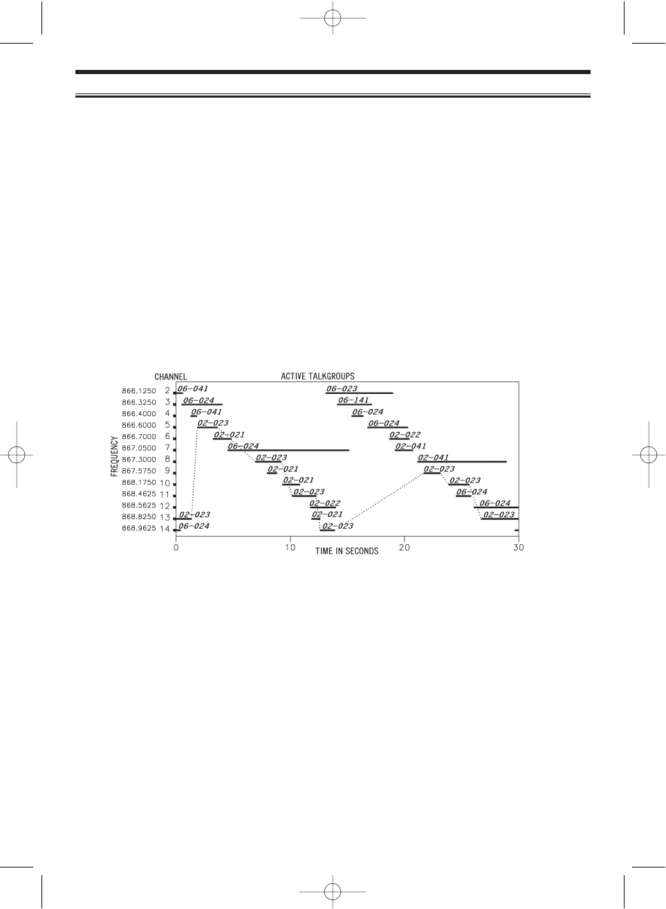
This chart shows a 30 second sample of EDACS transmissions. Eight different talkgroups
are using the system as their transmissions switch between the thirteen system frequencies.
Notice how the dotted line shows talkgroup 02-023 moving from channel to channel.Your
BC780XLT can clearly and automatically follow this talkgroup, or any other, as you select.
EDACS systems are organized in a logical way that keeps related talkgroups together. Your
scanner is designed to take maximum advantage of this organization to make your scanning
easy. It lets you zero in on just the part of the system you want to hear, whether it is an
individual channel or an entire department or city.
Programming EDACS System Frequencies
When you program EDACS frequencies, it is critical that you store each one in the
CORRECT LOCATION. By the nature of EDACS systems this is necessary for tracking. This
often is not the frequency order, so you must be sure you have the right sequence. Sources
for this information include www.trunktracker.com and www.bc780xlt.com.
BC780XLT1.qxd 10/08/2000 5:02 PM Page 49
50
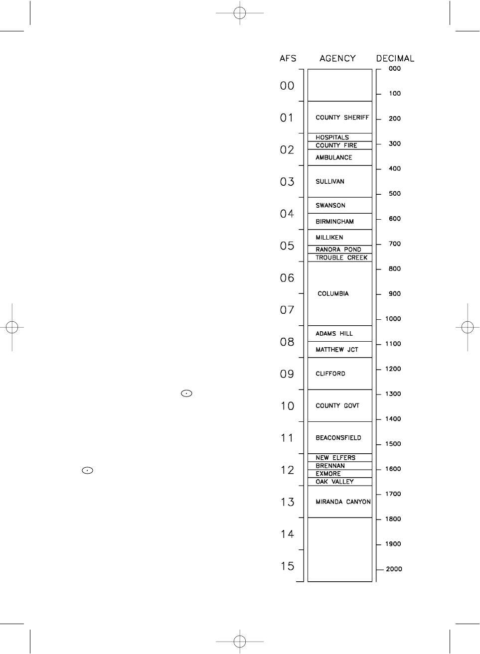
An EDACS®Trunked system
This chart shows how talkgroups are organized
within an EDACS system at the AGENCY level.
The individual talkgroups cannot be shown at this
scale because there are over 2000. However the
chart can show the 16 Agencies in this example.
The system is logical and easy to understand.
EDACS systems are typically arranged in an
outline structure.
The system users are given blocks of talkgroups.
Sizes vary but most large cities and other agencies
have blocks of 128 channels. Smaller cities have
only 64 or 32 channels.
In this example, the County Sheriff is agency 01.
The city of Sullivan is Agency 03. Adams Hill and
Matthew Junction share Agency 08.
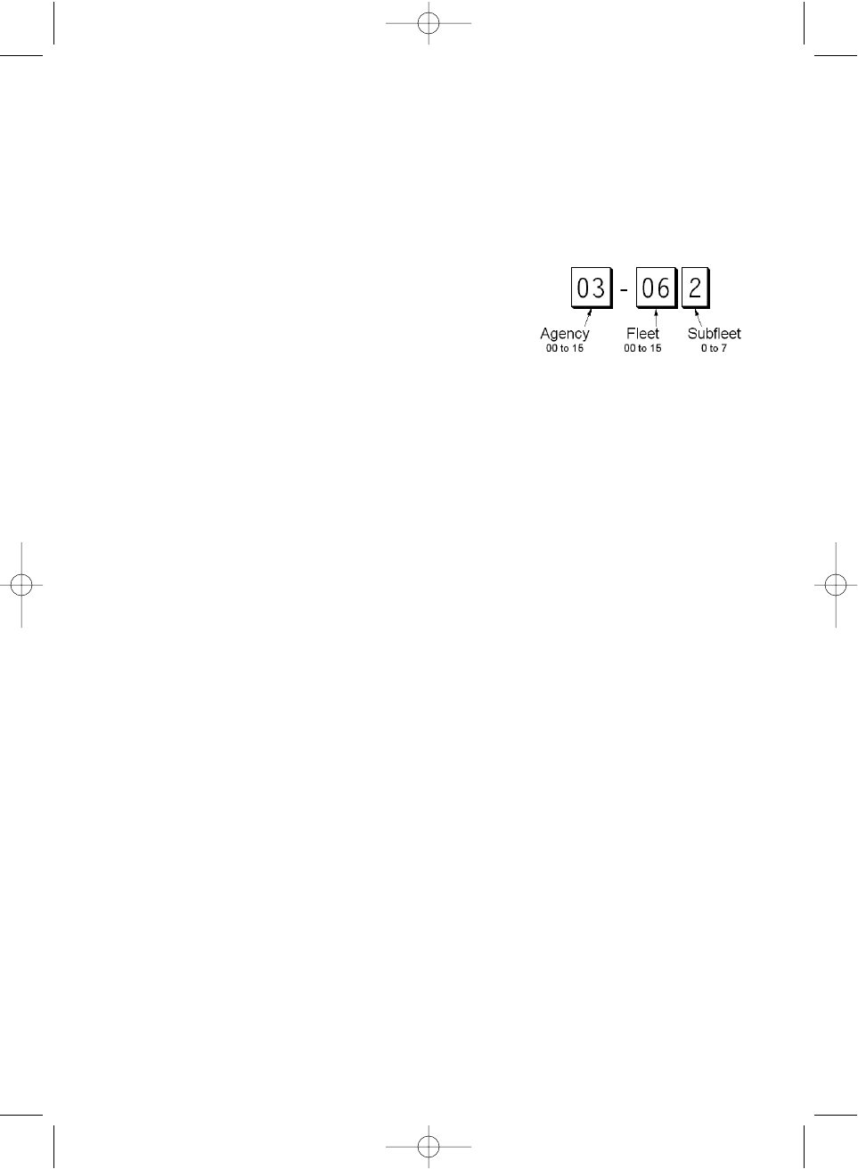
Your scanner shows EDACS talkgroups in AFS
(Agency-Fleet-Subfleet) format. This helps you see,
at a glance, who you are monitoring. And with the
partial-entry feature you can easily include nearby,
related channels in the same Fleet or Agency. You
can just as easily exclude entire unwanted Fleets
and Agencies.
When in Search mode, with the system frequencies
programmed, and your scanner locked to the control
channel, you can select a desired city by keying in
the AGENCY part of the AFS talkgroup. For
example, you can select the entire city of Sullivan
with 4 key presses zero, three, ,
SRCH
.
When you hear an interesting talkgroup, capture it to
your scan list by pressing
E
during the transmission.
Or HOLD on it by pressing the
HOLD
key.
If you want to monitor the Sullivan Police Dispatch
channel (which is talk group 03-062), press zero,
three, , zero, six, two,
HOLD
.
Your scanner can also work in DECIMAL format. This
talkgroup in decimal format is 434. But decimal
format does not give you any information about the
system hierarchy. For example Sullivan, in decimal,
uses channels from 384 to 511. This is not as easy
to remember as Agency 03. But decimal is useful if
you need to work from decimal talkgroup lists.
BC780XLT1.qxd 10/08/2000 5:02 PM Page 50
51
Special EDACS®Features
AFS Partial Entry Feature
AFS is Uniden's method of encoding EDACS talkgroups. AFS stands for 'Agency-Fleet-Subfleet'.
AFS talkgroups are used in all EDACS reception -- in ID SEARCH, ID LOCKOUT and ID SCAN
scanlists.The powerful AFS Partial Entry feature designed into the BC780XLT lets you use either a
complete talkgroup code, or just the most significant part.
This feature lets you expand or narrow searching and
scanning to one of 4 levels. By entering only the desired
part of an AFS talkgroup, you can select 2048 talkgroups,
128 talkgroups, 8 talkgroups, or a single talkgroup. For
example, you could program every talkgroup in a police
department with just 4 key presses.You can use the AFS
Partial Entry feature anywhere that you need to specify EDACS talkgroup.
Your BC780XLT can also enter or display EDACS talkgroups in decimal format (0-2047).
Press MENU - TRUNK DATA, and for banks selected as EDACS banks, select Item 8,
EDACS ID FORM and change it to Decimal.You can use this feature to translate decimal
talkgroups lists to the much more powerful AFS format.
Examples of how you might use AFS are shown above in the description of an EDACS
trunked system, and elsewhere in this manual. It is very easy to use. Be sure to become
familiar with AFS Partial Entry, and your scanning will become far more flexible and efficient.
Emergency Call Alert
Your BC780 alerts you when an EDACS Emergency transmission occurs.
EDACS systems often provide users with an 'Emergency' button on their radios. Users in
trouble can alert the dispatcher and other units and get priority access to the radio system.
When a user activates Emergency mode your scanner will flash EMERGENCY during the
entire transmission. At the beginning of each transmission it will sound a distinctive
emergency alert tone three times.
Patch Tracking
The BC780 can follow EDACS patched talkgroups.
EDACS systems sometimes bring several talkgroups together in a 'Patch'. A patch might be
used by a police agency at night to provide a single channel with a single dispatcher for a
wide area. A patch is created when a single, temporary talkgroup substitutes for the original
talkgroups. While the patch is running, which may be for hours or days, the original
talkgroups cease to be used. If you were monitoring one of these talkgroups, you might
think there was no traffic, but in fact the talkgroup was operating at the different
temporary number.
If a talkgroup in your Scan List is patched, your scanner will continue to receive it under its
new identity until the patch is ended. When a patch is being received, the radio will display
[PATCH ID], and will show the temporary common talkgroup plus all the included talkgroups
in a cycling display. The BC780 is limited to following one patch.
The temporary talkgroups used for patches are usually found in AFS code 15-xxx, and
sometimes 00-xxx.
BC780XLT1.qxd 10/08/2000 5:02 PM Page 51

52
LTR
®
Reception
LTR®Tracking
LTR®(Logic Trunked Radio) systems are trunking systems used primarily by business or
private communications service providers, such as taxicabs, delivery trucks, and repair
services. These systems encode all trunking information as digital subaudible data that
accompanies each transmission. Users on an LTR system are assigned to specific
talkgroups, which are identified by the radio as six digit numbers. These numbers are in the
form AHHUUU, where:
A= Area code (0 or 1)
H= Home repeater (01 through 20)
U= User ID (000 through 254)
When the scanner receives a transmission on a channel set to the LTR mode, it first
decodes the LTR data included with the transmission. In the ID Search mode, the scanner
stops on the transmission and displays the talkgroup ID on the display. In the ID Scan mode,
the scanner only stops on the transmission if the LTR data matches a talkgroup ID that you
have stored in the bank’s talkgroup ID list and have not locked out.
LTR systems are frequently programmed so that each radio has a unique ID code.
BC780XLT1.qxd 10/08/2000 5:02 PM Page 52

53
Motorola Reception
Motorola Tracking
There are really two types of Motorola trunking systems. These are usually referred to as
Type I and Type II systems. Type I only occurs on some 800 MHz systems. All VHF, UHF
and 900 MHz trunking systems use Type II.
One important distinction between these two systems is the amount of data transmitted by
each radio when its push-to-talk button (PTT) is pressed. Every radio in a trunked system is
assigned a unique ID so the central site computer can identify it when it’s used. Both Type I
and Type II systems place radios (or radio users) into groups, called talkgroups, and these
talkgroups are also assigned unique IDs. Some radios have access to only one talkgroup,
while others have access to many talkgroups. The talkgroup(s) each radio can access is
called the radio’s affiliation(s).
In a Type II system, when someone uses their radio, only the radio ID is transmitted when
PTT is pressed, whereas in a Type I system the radio ID and its current affiliation are both
transmitted when PTT is pressed.
Why the difference? Type II systems are slightly more advanced because the central
computer maintains a database which is used to determine each radio’s affiliation (s).
Changes to a Type II system are easier than Type I because the system manager only
needs to update the database instead of reprogramming individual radios.
Another difference between the systems is that Type I systems are arranged in a Fleet-
Subfleet hierarchy. For example, its possible for a city using a Type I system to designate 4
Fleets, each with 8 Subfleets. Their fleets might be the Police Department, the Fire
Department, Utilities, and Administration. The Police may decide to further divide their fleet
into subfleets such as Dispatch, Tactical Operations, Detectives, North, South, East and
West Side Patrols, and Supervisors. All the available police radios would then be assigned
to one of the police subfleets. Determining the exact Fleet-Subfleet hierarchy for a particular
area is referred to as Fleet Map Programming, which is discussed further in this manual.
The disadvantage of a Type I system is that when PTT is pressed, the brief burst of data
must contain the radio’s ID and its Fleet and Subfleet. This is three times the amount of data
a Type II system radio sends, and as a result Type I systems usually accommodate fewer
users than Type II systems.
Even though there are many Type II systems, Type I systems are still in use. There are also
Hybrid systems which are a combination of both Type I and Type II. Your scanner defaults to
monitor Type II systems, but its possible to select a Preprogrammed Fleet Map or create a
Custom Fleet Map for your area.
For VHF and UHF Type II trunking systems, you will need to know the base, spacing
frequencies and offset channels. See page 55 for details.
BC780XLT1.qxd 10/11/2000 11:11 AM Page 53
54
Fleet Map Programming
If you have programmed a trunk tracking bank for Motorola type and press
TRUNK
to start
Multi-Track, you will see user IDs display on your screen. Since the BC780XLT defaults to
Type II systems, all the IDs will appear as numbers. However, if you notice a mix of odd and
even user IDs, for example 6477, 2560, 6481, 6144, 1167, etc., then you are probably
monitoring either a Type I or Hybrid systems.
You may also notice that you are missing responses when you hold on an active ID. Unlike
Type II, Type I/Hybrid systems require a Fleet Map that sets specific Fleet-Subfleet
parameters. It is easy to select a Fleet Map for your scanner; what is not always easy is
selecting or programming a map that matches your particular area.
There are 16 preset Fleet Maps listed in the appendix that you can choose, and these are
usually a good place to start when setting up a Type I/Hybrid trunk tracking bank. If you
choose a preset map and still have difficulty following complete conversations, then you'll
have to program your own Fleet Map.
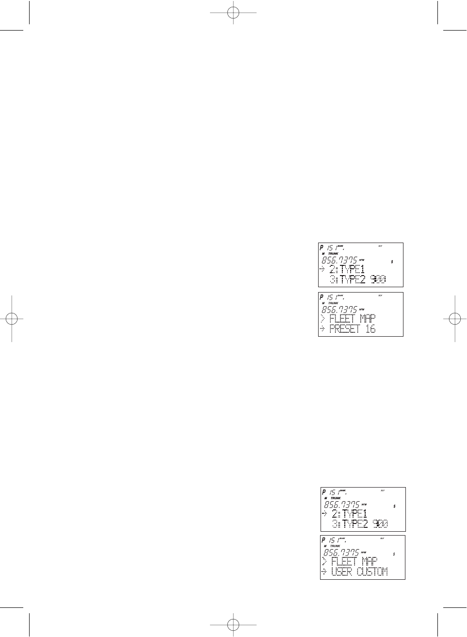
Selecting Preset Fleet Map
1. Select TYPE 1 for the Trunk Type. (Refer to “Selecting Trunking
System Type” on page 38.)
2. Select the map you want to program using ▲, ▼or
VFO and then press
E
,
SELECT
or VFO.
For example, PRESET 16.
The scanner returns to the other programming items.
Note: You will now begin to see Type I Fleet-Subfleet IDs. For example, 100-12, 100-9, 000-
12, 400-8, etc. See User Defined Fleet Maps in the Appendix for more information
about Type I IDs.
How do you know if the preset map is correct? You will have to listen to see if you're
following complete conversations. If not, you should try another preset map.
Programming a Fleet Map
You may want to read User Defined Fleet Maps in the Appendix before programming a Fleet
Map. It contains a detailed explanation of Scanner Fleet Map Programming, as well as a
table listing the Fleet Map Size Codes.
1. Select TYPE 1 for the Trunk Type. (Refer to “Selecting
Trunking System Type” on page 38.)
2. Select USER CUSTOM using ▲, ▼or VFO and then
press
E
,
SELECT
or VFO.
BC780XLT1.qxd 10/08/2000 5:02 PM Page 54
55
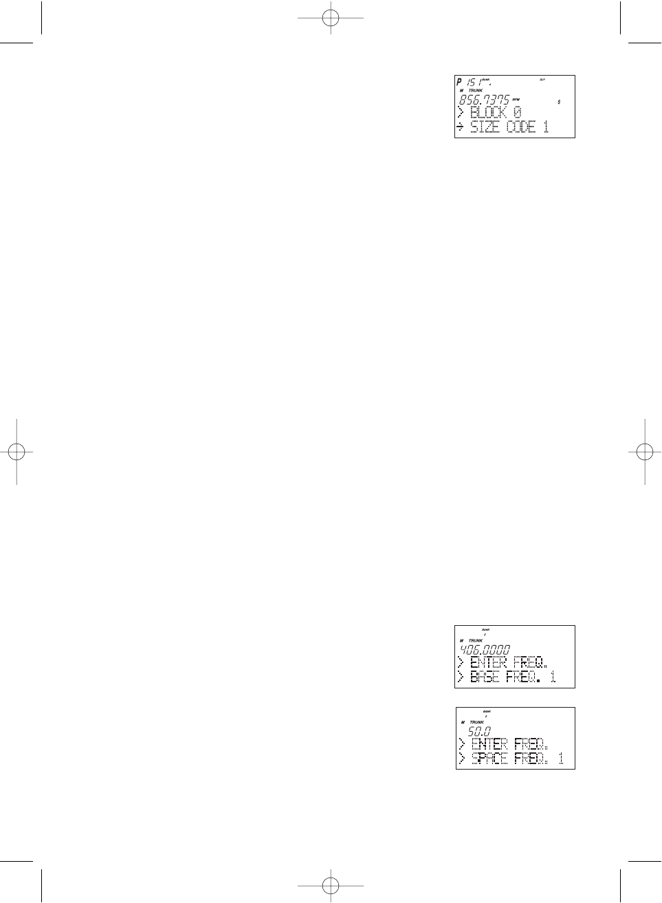
3. Select the size code for the first block using
▲, ▼, or VFO.
4. Press
E
,
SELECT,
or VFO.
The next available block displays.
5. Repeat step 3 and 4 until you have selected a size
code for each block.
For details about each size code, see Fleet Map Size
Codes in the Appendix.
Programming a Hybrid System
A Hybrid system is simply a Type I system with some blocks designated as Type II blocks. To
program a Hybrid system, follow the steps listed in Programming a Fleet Map in the previous
section. However, if you want a block to be Type II, select Size Code S-0.
When you begin searching a trunking bank with a Hybrid Fleet Map, you will see both types
of system IDs. That is, Type II IDs usually appear as an even number without a dash; Type I
IDs appear as a three or four digit number, followed by a hyphen, followed by a one or two
digit number.
Setting the Base, Spacing Frequencies and Offset Channel for Motorola
VHF/UHF Trunked Systems
To properly track Motorola VHF and UHF trunked systems you must enter what is known as
the base, the spacing frequencies and offset channels for each system.
To find these out, check the www.trunktracker.com or www.bearcat1.com/free.htm and
other web sites and frequency resources.
To enter the base, spacing frequencies and offset channel: (You can set up to three sets of
these, but almost all systems only use one set)
1. Press
MENU
.
2. Select TRUNK DATA - BANK NO. - TRUNK TYPE (TYPE2 UHF or VHF) - BASE
CONFIG using ▲, ▼or VFO and pressing
E
,
SELECT
or VFO.
3. Enter a new base frequency with the keypad.
4. Press
E
.
The display changes for entering the spacing frequency.
5. Enter a new spacing frequency with the keypad.
Note: You can only enter within a range of 5-100 kHz,
and 5 or 7.5 or 12.5 kHz multiples.
6. Press
E
.
The display changes for entering the offset channel.
BC780XLT1.qxd 10/08/2000 5:03 PM Page 55

56
7. Enter a new offset channel with the keypad.
Note: You can only input within a range of 380-759.
8. Press
E
.
The display changes for entering the next base frequency.
9. To exit from this mode, press
MENU
repeatedly.
Note: • If the system is not tracking properly, you may need to try a new base frequency or
offset channel or you may be missing frequencies from the system.
• You can set up to three base, spacing and offsets for Motorola VHF/UHF trunked systems.
10. The offset channel for the first set should be CH380 (just press
E
to confirm this as
the default).
11. After you have pressed
E
to confirm CH380, the display will change to allow you to set
the second (of a maximum of three) base/space/offset combinations. Since almost all
systems only use one set, press
MENU
to exit the programming mode and return
to scanning.
Toggling the Status Bit
On Type II trunking systems there is a method by which specialized types of communications
utilize unique talkgroup numbers. An emergency call will occur on a unique talkgroup from its
primary assignment, for example. Because the BC780XLT defaults to Status-Bit On mode,
you never need to worry about missing these transmissions. If you have programmed
talkgroup 33264 into Scan List memory, for example, and there is an emergency call within
the group, you will hear it on 33264.
The only time you may wish to turn Status Bits off is if you're trying to figure out the proper
fleet map of a Type 1 trunking system. To turn Status Bits off, enter into the menu mode and
select TRUNK DATA - BANK NO.- STATUS BIT. (This feature does not apply to EDACS
and LTR operation within the scanner.) Then use
HOLD/
▲or
LIMIT/
▼to change the setting
(on to off) and press
E
to program your change.
BC780XLT1.qxd 10/08/2000 5:03 PM Page 56

57
Control Channel Only Mode
When this function is activated, trunking is performed using control channel data only. Voice
channel (also known as "working channel") frequencies do not have to be programmed into
memory. When using this feature, the scanner will display "CC" and channel activity indicator
bars will not operate. This feature only applies to Motorola 800 MHz and 900 MHz systems.
To turn this function on, choose Motorola Type-2 800 MHz or 900 MHz or TYPE 1 by
selecting TRUNK DATA - BANK NO. - TRUNK TYPE. Then set to the desired control plan by
selecting TRUNK DATA - BANK NO. - CTRL CH ONLY.
You must choose one of 4 frequency plans before you begin to Control Channel Trunk. Note
that the default, Plan 1, is the most common. Read the description of the Plans below for
details on which may apply for you.
PLAN 1: Use Plan 1 if the last three digits of ALL the frequencies in use end in one of the
following three digits: 125, 375, 625, or 875 (example: 856.1125, 860.7375, 859.6625,
855.8875).
PLAN 2: If the last three digits of frequencies less than 869.0000 end in one of the
following three digits (125, 375, 625, or 875) AND if ANY other frequencies end in (000,
250, 500, or 750) use Plan 2.
PLAN 3: If the last three digits of ALL the frequencies in use end in one of the following
three digits (000, 250, 500, or 750) use Plan 3.
PLAN 4: If the last three digits of frequencies less than 866.0000 end in one of the
following three digits (000, 250, 500, or 750) AND if ANY other frequencies end in (125,
375, 625, or 875) use Plan 4.
Of course you will know the Control Channel frequency itself so that will help you determine
the proper Plan. If you try one plan and you receive errors (such as the scanner jumping to
channels that are obviously not part of the system), you should try an alternate Plan.
Note: You can assign a fleet map to Type 1 or Hybrid systems scanned in Control
Channel only mode by going into the menu. You can also program IDs, set delays,
alpha tags and all the other parameters for systems scanned in this mode.You can
then either search the system to find new IDs or you can program IDs into memory
and then scan them.
Note: The Control Channel Only feature is an extremely powerful tool. You can use it to
determine if systems you are familiar with may have added new frequencies or you
can use it to discover new systems by simply finding active control channels (using
Search) and then programming them for Control Channel operation only.
Remember that this feature only applies to Motorola 800 and 900 MHz systems,
that you do have to set the menu for the proper system type (800 Type 1 or Type II
or 900 MHz) and you do have to program the control channel frequency into
memory and press and hold the
TRUNK
key to identify the frequency as trunked.
BC780XLT1.qxd 10/08/2000 5:03 PM Page 57

58
Disconnect Tone Detect Option (End Code)
When this function is disabled, the radio looks for squelch before returning to the control
channel instead of waiting for the disconnect tone. Only in rare instances will you need to
adjust the default settings.
The condition to return to control channels depends on whether the signal is present or not.
To set this function on/off, enter TRUNK DATA - BANK NO. - END CODE.
BC780XLT1.qxd 10/08/2000 5:03 PM Page 58
59
Remote Interface
You can communicate and program your BC780XLT in numerous ways with peripheral
devices using the Remote Interface Cable port. This radio offers the following modes:
❖SMARTSCAN MODE
Automatically load frequencies, trunking talkgroups and fleetmaps from the Uniden
National Frequency Database server into your scanner using an external modem or an
internal modem included with a personal computer (PC).
❖REMOTE (PC Control) MODE
Program and control your scanner remotely from a PC using third party software (see the
flyer included in the box).
❖CLONE MODE
Clone all the frequencies, trunking talkgroups, and fleet maps programmed into your
scanner to another BC780XLT scanner.
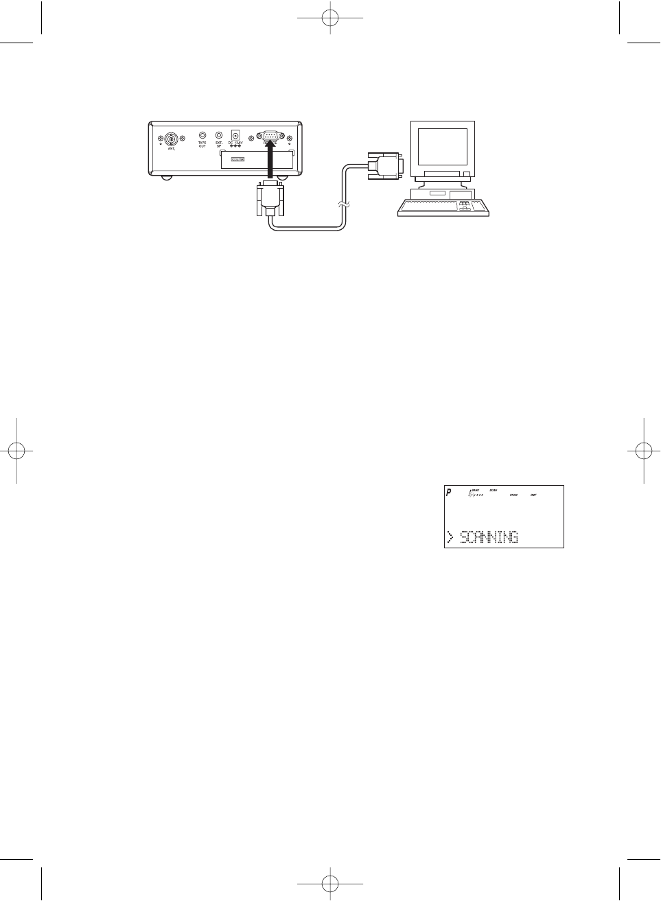
SmartScan Mode
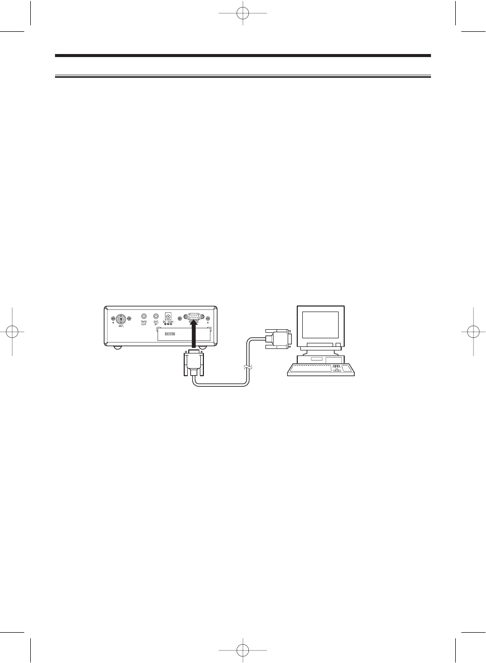
To connect Scanner to PC:
Plug the scanner end of the RS232C straight interface cable (purchased separately) into the
remote port on the rear of your scanner.
Plug the other end of the cable (DB-9 serial connector) into a personal computers serial
port. A few PCs may require an adapter, most will not. You may need a DB-9 to DB-25 null
modem adapter, or gender changer adapter, available at most computer stores. Of course,
make sure your PC is turned on.
To use SmartScan mode with an internal modem, you will need a small custom software
program to allow the serial port to talk with the internal modem and act as a simple pass
through device. To download this free program, go to Uniden's website, look up under
Scanners - “SmartScanner” or the BC 780XLT scanner, for the SmartScanner software. Run
this program and it should automatically set the port setting for you (although you can
override the settings). Make sure that you have a phone line plugged into the modem jack on
the back of your PC and your scanner is connected to the serial port of the PC using
the RS232C straight cable.
Cables and connectors are available for purchase by calling 1-800-722-6701
or check out www.bc780xlt.com.
BC780XLT1.qxd 10/08/2000 5:03 PM Page 59
60
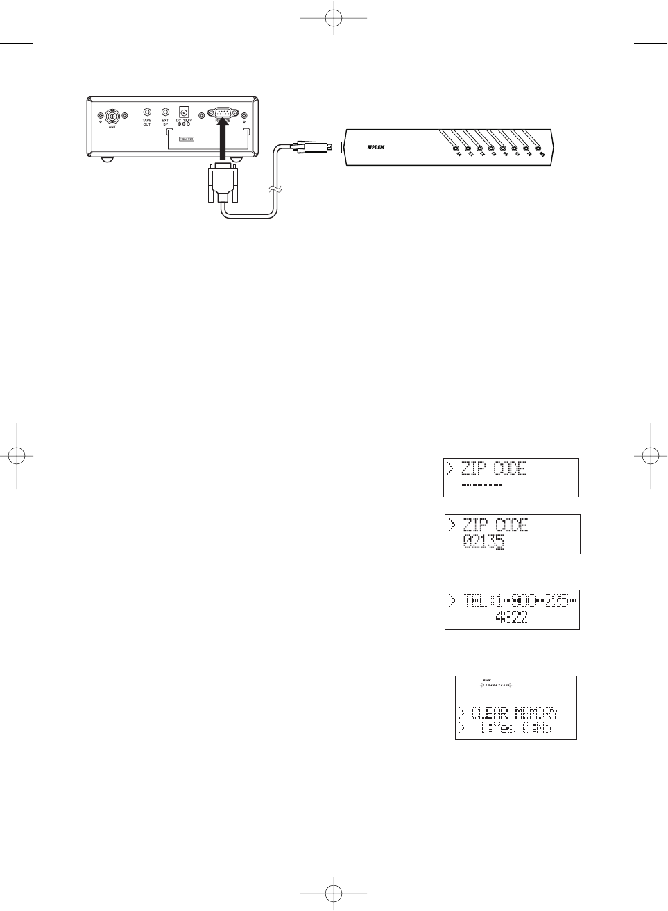
To connect Scanner to External Modem:
Plug the scanner end of the RS232C straight interface cable into the remote port on the rear
of your scanner. Plug the other end of the cable (DB-9 serial connector) into the external
modem. You may need a DB-9 to DB-25 (or DB-9) null modem adapter, available at most
computer stores. Of course, make sure your external modem is turned on. Make sure that
you have a phone line plugged into the modem jack on the back.
To perform the SmartScan Download:
You can automatically download frequencies, talkgroups and fleet maps form the Uniden
National Database server. After connecting to either an internal or external modem, using
the the steps above, turn the radio on.
1. Press
MENU
.
2. Select SYSTEM DATA - SMART SCAN - DOWNLOAD using ▲, ▼or VFO and pressing
E
,
SELECT
or VFO.
3. Using the keypad, enter the ZIP code for the area you
will be using your scanner.
For example, if your ZIP code is 02135.
4. Press
E
or
SELECT
, the ZIP code is stored into memory.
The dial-in telephone number appears on the display.
Note: If you want to change the number, input a number
(max. 20 digit) using the keypad then press
E
.
5. Press
SELECT.
The memory clear message appears
on the display.
Press
1
to start clearing.
Note: If you want to prevent some banks from being
overwritten by the frequency download or memory
clear operation, go to Bank Lock. (see page 62.)
BC780XLT1.qxd 10/08/2000 5:03 PM Page 60
61
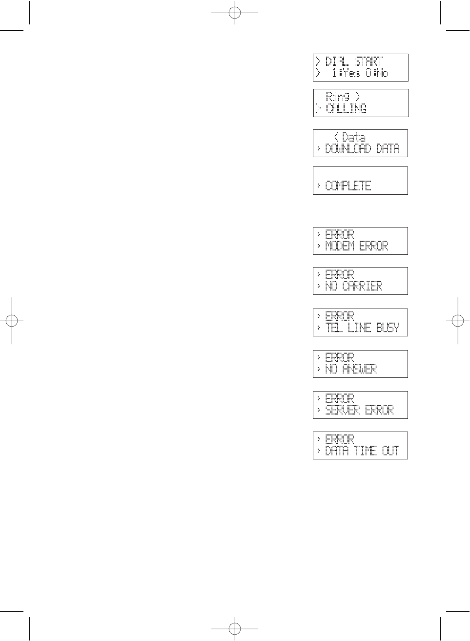
6. After clearing, the DIAL START message appears.
Press
1
to start dialing.
7. If the connection is successful, the scanner starts
frequency downloading.
COMPLETE
will be displayed
when your downloading is completed.
8. To start the scanner, turn the unit off then on.
If downloading is not successful, one of the following error messages will appear.
Modem Access Error:
No Carrier:
Telephone Line Busy:
No Answer:
Server Connect Error
Data Idle Time Out
Note: If the scanner does not display
DOWNLOAD DATA
, disconnect the access by pressing
E
.
Then, make sure the modem is connected properly, and try again.
Note: The number preprogrammed into your scanner for downloading frequencies is
1-900-225-4822. There is a $0.99 per minute charge for using the SmartScan
database. To get current frequencies, as well as special /sporting event frequencies,
regularly update your scanner by using SmartScan.
Note: If you are unable to dial a 900 number, check with your local phone company to find
out if you have a 900 block on your phone line. This will prevent you from dialing to
the server.
BC780XLT1.qxd 10/08/2000 5:03 PM Page 61
62
Menu for SmartScan
In the menu mode (SYSTEM DATA - SMART SCAN), you can change several parameters
used for SmartScan.
• Bank lock
• Transfer speed
• Flow control setting
• Dial type
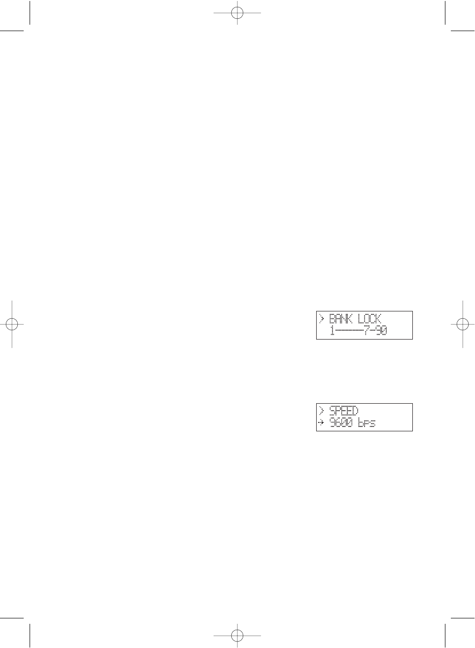
Bank Lock
SmartScanner will overwrite frequencies that you have already programmed into your
scanner. To save the previously programmed frequencies, you can lock out specific banks
prior to calling the database as follows:
To turn on this feature, enter into the menu mode.
1. Press
MENU
.
2. Select SYSTEM DATA using ▲, ▼or VFO and pressing
E
,
SELECT
or VFO.
3. Select SMART SCAN using ▲, ▼or VFO and pressing
E
,
SELECT
or VFO.
4. Select BANK LOCK using ▲, ▼or VFO and pressing
E
,
SELECT
or VFO.
5. Press the bank numbers using the
1
-
9
and
0
key (for
bank 10) that you wish to lock out from programming so
that they will not be overwritten during the download.
6. Press
E
.
Transfer Speed
You can choose the following transfer speeds.
300, 2400, 4800, (9600), 19200 bps
9600 is the default.
Press
E
to exit.
BC780XLT1.qxd 10/08/2000 5:03 PM Page 62
63
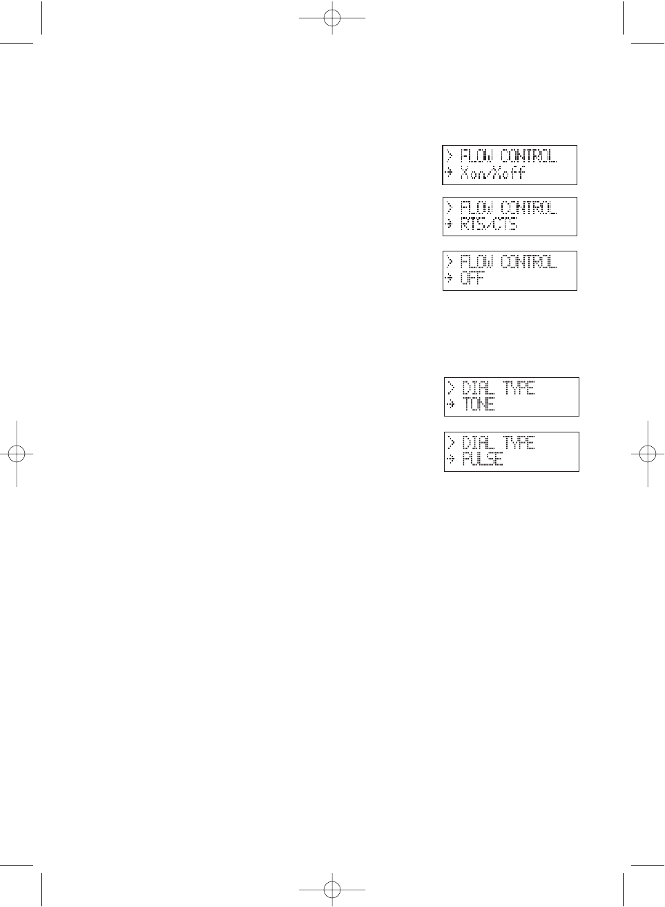
Flow Control
You can choose the following flow control settings.
Xon/Xoff is the default.
The initial display appears.
Press
HOLD/
▲for RTS/CTS.
Press
HOLD/
▲again for non flow control.
Press
HOLD/
▲again to turn off the flow control.
Press
E
when desired setting is displayed.
Dial Type
You can choose the Dial Type setting.
TONE is set as a default.
You can change it to PULSE by pressing
HOLD/
▲.
Smart Scanner Tips
There are literally hundreds of thousands of public safety radio licenses in the United States.
The editors of the Uniden National Frequency Database have poured over these records to
provide you with the most accurate possible download of frequencies for whichever area of
the country you desire. Because of the volume of data, and because some systems operate
on expired licenses or digital radio systems (which are not included in the data set as they
cannot be monitored), we cannot guarantee that you will receive every active public safety
frequency in your area.
If you find any flaws in your data and you would like to offer suggestions, please e-mail them
to us at smartscanner@aol.com or mail them to us at SmartScanner National Database,
P.O. Box 610428, Newton Highlands, MA 02468. Due to the volume of mail we receive, you
may not receive a reply.
BC780XLT1.qxd 10/08/2000 5:03 PM Page 63

64
The SmartScanner database downloads frequency and trunking talkgroups (if applicable for
your area) to the scanner using the following order:
1. All licenses within your zip code.
2. All licenses within your community (with more than one zip code)
3. All your county licenses (such as County Sheriff)
4. All the licenses for all the communities within your county (in random order).
5. Statewide licenses (such as Highway Patrol, state forestry, DOT, but not trunking)
6. National licenses (such as common ambulance, marine, and Family Radio Service
channels).
Look at the web sites Uniden.com and Trunktracker.com for further information. The
downloads are not available through the Internet at this time.
A few notes about the frequency download order:
1. The scanner fills up less than its allotted 500 channels if there are not more than 500 of
the above types of licenses in your area.
2. If there are more than 500 of the above listed types of licenses, or you have locked-out
some banks prior to the download using the Program Lock feature, the scanner may run
out of memory locations and you may not, for example, receive part or all of your county,
state or nationwide data.
3. If you wish to also receive a download of frequencies and talkgroups from an adjacent
county, lock those banks you wish to keep, shut the scanner off, turn it back on again and
enter the SmartScanner download mode. Then enter a zip code from a community within
the adjacent county.
4. The SmartScanner editors used their best efforts to delete digital and MDT (mobile data
terminal) computer records from the database; however, it would be impossible to delete
them all. Therefore, you may hear some non-voice transmissions on the frequencies
downloaded into your scanner. Make sure you have TRUNK mode on to see if these are
control channels for a trunking system. If not, then you should lock these frequencies out
or delete them by entering a new frequency or entering
0
,
E
.
5. After the download, be sure to press the
TRUNK
key to see if you have trunk systems
now loaded for your area. The BC 780XLT cannot track such systems unless the trunking
mode is on. Performance of the scanner is not hindered if you have TRUNK mode on and
you do not have a trunk system programmed.
6. If you have a trunk system programmed (you can tell by seeing if the display shows ID
SCAN at any time), be sure to put the radio into Trunk Search mode at some point to
discover new talkgroups within the trunk system that have not been pre-programmed into
the SmartScanner database.
BC780XLT1.qxd 10/08/2000 5:03 PM Page 64
65
Remote (PC Control) Mode
To connect Scanner to PC:
Plug the scanner end of the RS232C straight interface cable into the remote port on the rear
of your scanner.
Plug the other end of the cable (DB-9 serial connector) into a personal computers serial
port. A few PCs may require an adapter, most will not. You may need a DB-9 to DB-25 null
modem adapter, or gender changer adapter, available at most computer stores. Of course,
make sure your PC is turned on.
To program your scanner:
You can program and control your scanner remotely from a PC using third party software.
After connecting the scanner to a PC, turn the radio on.
To use the Remote (PC Control) mode, you must purchase third party software and use as
directed. Make sure that your scanner is connected to the serial port of the PC using the
RS232C straight cable.
Start Remote Mode:
Press
E
key for 2 seconds. REMOTE mode is
selected. To distinguish from Normal operation
mode, “
RMT
” icon appears.
A unique feature of the BC780XLT is that all the
front panel keys as well as the VFO on the radio
remain operational in remote mode.
For information on purchasing third party software to program and control your BC 780XLT,
see the flyer included in the box with this radio.You can also go to www.bc780XLT.com on
the Internet or call 1-800-722-6701 for more information on software custom-designed for
your Bearcat BC780XLT.
PC Control Parameter
For your information:
Transfer speed : 2400/4800/9600/19200 bps (adjustable)
Start/Stop : 1 bit, 1 bit
Data Length : 8 bit
Parity bit : None
Code : ASCII code
Flow Control : None
Return Code : Carriage Return only
BC780XLT1.qxd 10/08/2000 5:03 PM Page 65
66
Change Transfer Speed
To change transfer speed, enter into the menu mode.
1. Press
MENU
.
2. Press ▲or ▼to select SYSTEM DATA and then
press
E
.
3. Press ▲or ▼to select PC CONTROL and then
press
E
.
4. To change the transfer speed, press ▲or ▼. Then press
E
.
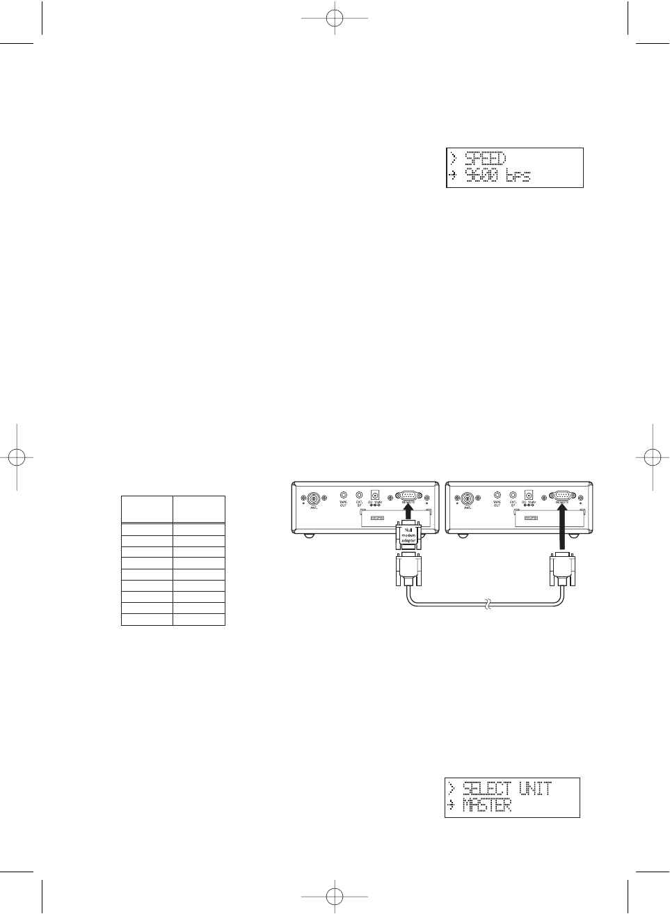
Clone Mode
You will need to purchase an RS232C cable and a null modem adapter. RS232C cables are
available as male to male or male to female. Even if the cable you buy already has the Male
to Male connectors, you will still have to have the null modem adapter. Below you will see
the pin connections that are internal to a standard device. (These items are available at your
local electronics stores.)
To connect the scanner to scanner:
Plug the male end of the RS232C straight interface cables into the remote port on the rear of
one of the two scanners. Then connect the DB-9 to DB-9 null modem adapter to the cable.
Then plug the the other side of the null modem adapter to the other scanner. (DB9 Gender
changers are also available at your local electronics store.)
You can clone all of the programming of one BC780XLT into another, including frequencies,
talkgroup IDs, alpha tags, delay settings, etc. After connecting the two scanners, turn the
radios on. Prepare each scanner for clone mode as follows.
1. Press
MENU
.
2. Select SYSTEM DATA - CLONE using ▲, ▼or VFO and pressing
E
,
SELECT
or VFO.
3. Determine the scanner that has the frequency data that you want to transfer. This one
must be set up as the “Master Unit”, and the other must be set as the “Slave Unit”.
4. On the scanner that is the “Master Unit”, select
MASTER
, then press
E
.
Female
DB9
Male
DB9
14
23
32
46 & 1
55
64
78
87
9Not used
Null Modem Adapter
Pin connections
BC780XLT1.qxd 10/08/2000 5:03 PM Page 66
67
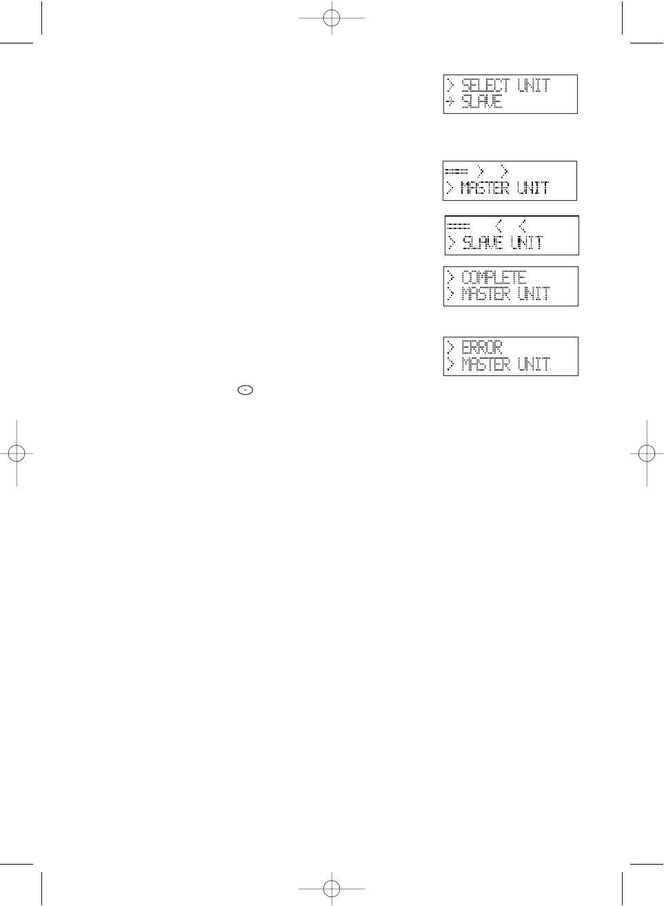
5. On the scanner that is the “Slave Unit”,
select
SLAVE
, then press
E
.
6. Press the SCAN key on both scanners. The data transfer is started from the Master Unit
to the Slave Unit.
During the data transfer, both scanners show
the following displays.
When the data transfer is completed,
COMPLETE
displays.
If the data transfer is not successful, the
following error message will appear.
Note: To clear
ERROR
, press .
To exit the clone mode, press the menu key repeatedly.
Note: Once you have completed the cloning of the scanners, reset by turning the scanners
off and then on again. This is particularly important to know if you wish to clone
another scanner right away.
BC780XLT1.qxd 10/08/2000 5:03 PM Page 67