Verifone MX870RFID Credit Card Verification System User Manual 23431
VeriFone Inc Credit Card Verification System 23431
Verifone >
Contents
- 1. Users Manual Part 1
- 2. Users Manual Part 2
Users Manual Part 1
Part Number 23431, Revision B.2
VERIFONE
CONFIDENTIAL
TEMPLATE REV E
Mx800 Series
Installation Guide
All rights reserved. No part of the contents of this document may be reproduced or transmitted in any form without the written
permission of VeriFone, Inc.
The information contained in this document is subject to change without notice. Although VeriFone has attempted to ensure the
accuracy of the contents of this document, this document may include errors or omissions. The examples and sample programs are
for illustration only and may not be suited for your purpose. You should verify the applicability of any example or sample program
before placing the software into productive use. This document, including without limitation the examples and software programs, is
supplied “As-Is.”
VeriFone, Inc.
2099 Gateway Place, Suite 600
San Jose, CA, 95110 USA
www.verifone.com
Part Number 23431, Revision B.2
Mx800 Series Installation Guide
© 2005 VeriFone, Inc.
VeriFone, the VeriFone logo, Omni, VeriCentre, Verix, and ZonTalk are registered trademarks of VeriFone. Other brand names or
trademarks associated with VeriFone’s products and services are trademarks of VeriFone, Inc.
All other brand names and trademarks appearing in this manual are the property of their respective holders.
Comments? Please e-mail all comments on this document to your local VeriFone Support Team.

MX800 SERIES INSTALLATION GUIDE 3
CONTENTS
PREFACE . . . . . . . . . . . . . . . . . . . . . . . . . . . . . . . . . . . . . . . 5
Intended Audience . . . . . . . . . . . . . . . . . . . . . . . . . . . . . . . . . . . . . . . . . . . . . . . . 5
Document Organization . . . . . . . . . . . . . . . . . . . . . . . . . . . . . . . . . . . . . . . . . . . . 5
Conventions Used in This Document . . . . . . . . . . . . . . . . . . . . . . . . . . . . . . . . . . 5
Abbreviations . . . . . . . . . . . . . . . . . . . . . . . . . . . . . . . . . . . . . . . . . . . . . . . . . . . . 6
CHAPTER 1
Features Overview. . . . . . . . . . . . . . . . . . . . . . . . . . . . . . . . . . . . . . . . . . . . . . . . . . . . . . . . 7
Mx800 Series . . . . . . . . . . . . . . . . . . . . . . . . . . . . . . . . . . . . . . . . . . . . . . . . . 7
Features and Benefits . . . . . . . . . . . . . . . . . . . . . . . . . . . . . . . . . . . . . . . . . . . . . 8
Factory Options . . . . . . . . . . . . . . . . . . . . . . . . . . . . . . . . . . . . . . . . . . . . . . . . . . 9
Smart Card Module. . . . . . . . . . . . . . . . . . . . . . . . . . . . . . . . . . . . . . . . . . . . . 9
Ethernet Module . . . . . . . . . . . . . . . . . . . . . . . . . . . . . . . . . . . . . . . . . . . . . . . 9
Polarized Screen. . . . . . . . . . . . . . . . . . . . . . . . . . . . . . . . . . . . . . . . . . . . . . . 9
Speakers. . . . . . . . . . . . . . . . . . . . . . . . . . . . . . . . . . . . . . . . . . . . . . . . . . . . . 9
Optional Modules . . . . . . . . . . . . . . . . . . . . . . . . . . . . . . . . . . . . . . . . . . . . . . . . . 9
Contactless Reader Module . . . . . . . . . . . . . . . . . . . . . . . . . . . . . . . . . . . . . 10
Privacy Screen . . . . . . . . . . . . . . . . . . . . . . . . . . . . . . . . . . . . . . . . . . . . . . . 10
Applications . . . . . . . . . . . . . . . . . . . . . . . . . . . . . . . . . . . . . . . . . . . . . . . . . . . . 10
Total Cost of Ownership. . . . . . . . . . . . . . . . . . . . . . . . . . . . . . . . . . . . . . . . . . . 10
CHAPTER 2
Installation Installing the Device . . . . . . . . . . . . . . . . . . . . . . . . . . . . . . . . . . . . . . . . . . . . . . 13
Installing Countertop Wedge. . . . . . . . . . . . . . . . . . . . . . . . . . . . . . . . . . . . . 15
Stand Mount . . . . . . . . . . . . . . . . . . . . . . . . . . . . . . . . . . . . . . . . . . . . . . . . . 16
Installing Optional Modules . . . . . . . . . . . . . . . . . . . . . . . . . . . . . . . . . . . . . . . . 17
Installing Smart Card Modules . . . . . . . . . . . . . . . . . . . . . . . . . . . . . . . . . . . 17
Installing SAM Cards – Additional Steps . . . . . . . . . . . . . . . . . . . . . . . . . . . . . . 18
Installing Trim Plate . . . . . . . . . . . . . . . . . . . . . . . . . . . . . . . . . . . . . . . . . . . . . . 18
Connecting the Device . . . . . . . . . . . . . . . . . . . . . . . . . . . . . . . . . . . . . . . . . . . . 19
Multiport Cable . . . . . . . . . . . . . . . . . . . . . . . . . . . . . . . . . . . . . . . . . . . . . . . 19
Disconnecting Multiport. . . . . . . . . . . . . . . . . . . . . . . . . . . . . . . . . . . . . . . . . 19
Connecting ECR in Tailgate Mode . . . . . . . . . . . . . . . . . . . . . . . . . . . . . . . . 20
Connecting to a Host PC . . . . . . . . . . . . . . . . . . . . . . . . . . . . . . . . . . . . . . . 20
Connecting to the Ethernet LAN . . . . . . . . . . . . . . . . . . . . . . . . . . . . . . . . . . 21
Connecting to USB Host or Hub . . . . . . . . . . . . . . . . . . . . . . . . . . . . . . . . . . 21
Power Up with the Multiport Cable . . . . . . . . . . . . . . . . . . . . . . . . . . . . . . . . . . . 21
Power Up without the Multiport Cable . . . . . . . . . . . . . . . . . . . . . . . . . . . . . . . . 22
CHAPTER 3
Maintenance Cleaning the Terminal . . . . . . . . . . . . . . . . . . . . . . . . . . . . . . . . . . . . . . . . . . . . 23
Smart Card Reader . . . . . . . . . . . . . . . . . . . . . . . . . . . . . . . . . . . . . . . . . . . . . . 23
CHAPTER 4
Troubleshooting Blank Display . . . . . . . . . . . . . . . . . . . . . . . . . . . . . . . . . . . . . . . . . . . . . . . . 25
Serial Port Does Not Work . . . . . . . . . . . . . . . . . . . . . . . . . . . . . . . . . . . . . . 25

CONTENTS
4MX800 SERIES INSTALLATION GUIDE
Transaction Fail to Process . . . . . . . . . . . . . . . . . . . . . . . . . . . . . . . . . . . . . 26
No Response From the Stylus . . . . . . . . . . . . . . . . . . . . . . . . . . . . . . . . . . . 26
Gap in Captured Signature . . . . . . . . . . . . . . . . . . . . . . . . . . . . . . . . . . . . . . 26
No Response From the Touch Panel . . . . . . . . . . . . . . . . . . . . . . . . . . . . . . 27
CHAPTER 5
VeriFone Service
and Support Return a Terminal for Service. . . . . . . . . . . . . . . . . . . . . . . . . . . . . . . . . . . . . . . 29
Accessories . . . . . . . . . . . . . . . . . . . . . . . . . . . . . . . . . . . . . . . . . . . . . . . . . . . . 31
Optional I/O Modules . . . . . . . . . . . . . . . . . . . . . . . . . . . . . . . . . . . . . . . . . . 31
Optional Accessories . . . . . . . . . . . . . . . . . . . . . . . . . . . . . . . . . . . . . . . . . . 31
Cables. . . . . . . . . . . . . . . . . . . . . . . . . . . . . . . . . . . . . . . . . . . . . . . . . . . . . . 31
Documentation . . . . . . . . . . . . . . . . . . . . . . . . . . . . . . . . . . . . . . . . . . . . . . . 33
Support Packages. . . . . . . . . . . . . . . . . . . . . . . . . . . . . . . . . . . . . . . . . . . . . 33
CHAPTER 6
Specifications Mx800 Series Terminal Specifications . . . . . . . . . . . . . . . . . . . . . . . . . . . . . . . . 35
INDEX . . . . . . . . . . . . . . . . . . . . . . . . . . . . . . . . . . . . . . . . . A
MX800 SERIES INSTALLATION GUIDE 5
PREFACE
This guide is your primary source of information for setting up and installing the
Mx800 Series family of terminals.
Intended
Audience This guide is useful for anyone installing and configuring the Mx800 Series series
terminals. Basic description of the terminal features are also provided.
Document
Organization This guide is organized as follows:
Chapter 1, Features, explains the features of the Mx800 Series series terminals.
Chapter 2, Installation, explains the installation procedure of the Mx800 Series
series terminals.
Chapter 3, Maintenance, explains how to maintain your Mx800 Series series
terminals.
Chapter 4, Troubleshooting, provides trouble shooting guidelines, should you
encounter a problem in terminal installation configuration.
Chapter 5, VeriFone Service and Support, provides information on contacting your
VeriFone representative or service provider. You will also find information on how
to order accessories or documentation from VeriFone.
Chapter 6, Specifications, provides information on power, environment and
dimensions of the hardware.
Conventions
Used in This
Document
The following table describes the conventions used:
Table 1 Document Conventions
Convention Meaning
Blue Text in blue indicates terms that are cross referenced.
Italics Italic typeface indicates book titles or emphasis.
ScreenText ScreenText format is used while specifying on screen text, such
as text that you would enter at a command prompt, or to provide
an URL.
NOTE The pencil icon is used to highlight important information.
CAUTION The caution symbol indicates hardware or software failure, or
loss of data.

PREFACE
Abbreviations
6MX800 SERIES INSTALLATION GUIDE
Abbreviations The following table describes the Abbreviations used:
Table 2 Abbreviations
Convention Meaning
ECR Electronic Cash Register
DUKPT Derived Unique Key Per Transaction
MRA Merchandise Return Authorization
LAN Local Area Network
PED PIN Entry Device
RFID Radio Frequency Identification
SAM Security Access Module
TIFF Tagged Image File Format
USB Universal Serial Bus
VGA Video Graphics Array

VERIFONE
CONFIDENTIAL
TEMPLATE REV E
MX800 SERIES INSTALLATION GUIDE 7
CHAPTER 1
Features
This chapter presents an overview and feature list for the Mx800 Series.
The Mx800 Series terminals are designed to offer multi-lane retailers outstanding
flexibility with the help of the terminals' unique modular design. The terminals
support a full line of payment and value-added applications such as loyalty or pre-
paid cards. In addition, they are easy to use, secure, and highly reliable–backed
by VeriFone's two decades of leadership in electronic payment.
Overview
The Mx800 Series terminal offers retailers the opportunity to efficiently mix the
terminals within the same store or chain of stores–saving time and money on
implementation, maintenance, and training.
M
x
800 Series
Mx800 Series terminals offer outstanding flexibility due to the modular design.
Modules that can be added include:
•Signature capture
•EMV smart cards
NOTE VeriFone ships variants of the Mx800 Series for different markets. Your terminal
may have a different configuration.
Share the same architecture Linux
Similar printed circuit boards.
Many of the same IBM, NCR, or Multipay
(PP201) applications.
Upgrade modules Terminals in different locations can be
equipped with different modules, as needed.
Built-in upgradability protects a retailer's
investment, allowing stores to adapt to
changing trends.
Different cabling and power
supplies
Reduces cost by simplifying implementation
and maintenance.
Same mounting stands and
wedges
Share the same keyhole pattern for secure
mounting.
Similar footprint and “look and
feel”
Offers consistency and simplifies training.
Mx800 Series is operated exclusively by touch
screen.

FEATURES
Features and Benefits
8MX800 SERIES INSTALLATION GUIDE
VERIFONE
CONFIDENTIAL
TEMPLATE REV E
•Ethernet/USB (Universal Serial Bus) connectivity. USB port supports devices
such as an electronic cash register (ECR) or PC that uses a USB connection
•Contactless smart cards using radio frequency identification (RFID) based on
ISO 14443 standards.
The terminals support a full line of payment capabilities and feature an easy-to-
use ATM style interface to reduce clerk errors and speed checkout lanes.
The Signature capture capability allows capture of virtual signatures, which are
stored as tagged image file format (TIFF) files using capacitive touch technology.
As the Mx800 Series terminal is operated exclusively by touch panel, VeriFone
offers a signature capture stylus that uses capacitive touch screen technology.
The Mx800 Series terminal is VeriFone's first 1/4 VGA payment devices. The
terminals offer:
•A crisp, color display and attractive, upscale appearance that appeals to many
retailers.
•Modular design that incorporates upgrade modules.
•A long-lasting, scratch-resistant capacitive touch screen that allows
consumers to make selections with their fingertip or electronic stylus.
•Large display that handles signature capture, scrolling line item detail,
regulatory disclosures, credit applications, and more.
•Smallest footprint of any VGA product on the market.
Features and
Benefits
The following are the features and benefits for Mx800 Series terminal:
Table 3 Features and Benefits
Features Benefit
Optional upgradable modules Lets retailers economically address today's needs,
while adding capabilities as desired; protects
investment.
Safety glass touch panel Capacitive and electrostatic technologies highly
effective; better response with fingertip and active
stylus; scratch-resistant.
Signature capture capability Speeds up customers through lanes; allows digital
storage and retrieval-lowering costs.
Triple-track magnetic card
reader
Logically oriented for improved read rates; handles
all mag-stripe cards, including driver's licenses.
Smart card reader/writer Accepts chip cards conforming to the latest global
standards (EMV 4.0)
Visa PED-compliant PINpad Virtual PINpad complies with Visa regulations for
improved security.
1/4 VGA display High resolution (320 x 240 pixels), 1/4 VGA color
display; attractive, modern, upscale, and highly
readable.

FEATURES
Factory Options
MX800 SERIES INSTALLATION GUIDE 9
VERIFONE
CONFIDENTIAL
TEMPLATE REV E
Factory Options
Factory options are available for the Mx800 Series terminal depending on your
terminal needs.
Smart Card Module
The smart card module fully conforms to global EMV standards, allowing
consumers to use smart cards to complete the transactions under guidelines
originally formulated by Europay, MasterCard, and Visa (EMV). Smart cards are
increasing in popularity in many regions worldwide. They can be used for payment
transactions as well as for a wide array of value-added applications such as
loyalty, gift card, and pre-pay cards.
Ethernet Module
The Ethernet module allows you to connect Ethernet-based LANs for high-speed
data transfer. It has a broad range of applications which include streamlining the
back-end clearing, and settlement, or to efficiently capture consumer data at the
POS.
Polarized Screen
Polarized screen prevents a non-user from viewing the display screen information
from an angle unless the user is directly in front of the display.
Speakers
The Mx800 Series terminal has built-in speakers for tones, prompts and music
line-out port available to drive external powered speakers.
Privacy screen PED-compliant privacy screen, protecting the
consumer's PIN entry.
Sophisticated security
protections
Includes 3DES encryption, Master Key/Session Key
and Derived Unique Key Per Transaction (DUKPT)
key management; also incorporates VeriShield file
authentication and tampering safeguards to
minimize fraud.
32-bit microprocessor Streamlines processing, even on complex
transactions; keeps lanes moving.
16 MB of memory (16 MB of
flash)
Ample memory to support multiple payment and
value-added applications simultaneously.
Ethernet/USB connectivity Allows LAN connections for high-speed data transfer
and back-end clearing, and settlement; supports
connections to ECRs and PCs using USB or
Ethernet.
RS-232/RS-485 ports Provides connectivity for ECRs in tailgate mode
using RS-485, and for peripherals such as printers
and bar code scanners using RS-232.
Audio Includes output jacks for external speakers.
Table 3 Features and Benefits (Continued)
Features Benefit

FEATURES
Optional Modules
10 MX800 SERIES INSTALLATION GUIDE
VERIFONE
CONFIDENTIAL
TEMPLATE REV E
Optional
Modules
The Mx800 Series terminal offers upgradable modules that can be installed in the
factory or upgraded after distribution to the field. All modules can be installed
easily and efficiently. Complete installation instructions are found in the Installing
Optional Modules section.
Contactless Reader
Module
The optional contactless smart card module incorporates RFID technology based
on the ISO 14443 worldwide standard. The “tap-and-go” design conforms to
AMEX and MasterCard specifications. Smart cards are read when it is placed in
close proximity – 1 to 3.9 in. (2.5 to 10 cm) – to the reader, reducing wear and tear
on card readers and cards. Contactless readers can be used to support any
number of payment and value-added applications. See Installing Optional
Modules for more information.
Privacy Screen
The Mx800 Series series terminals includes an optimal, PED-compliant privacy
screen to protect the customer’s PIN entry. See I/O Module for installation
procedures.
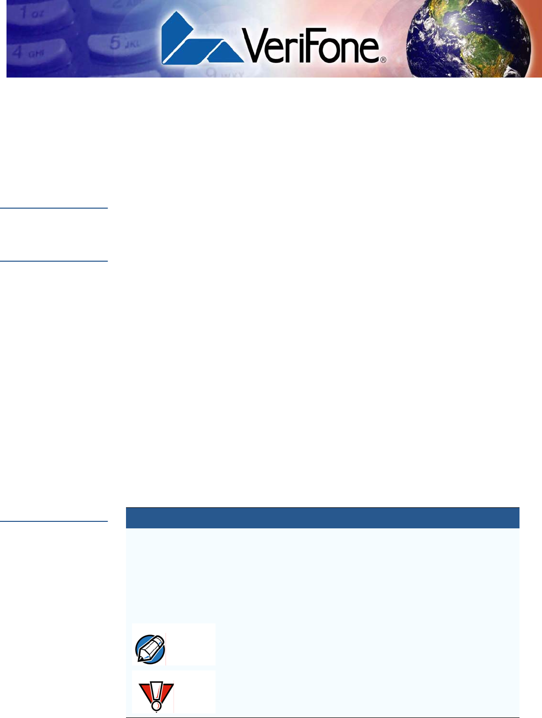
NOTE Install VeriFone's Mx800 Series terminal privacy shield to ensure compliance with
ISO 9564 standards and Visa PED requirements.
FEATURES
Applications
MX800 SERIES INSTALLATION GUIDE 11
VERIFONE
CONFIDENTIAL
TEMPLATE REV E
Figure 1 Mx870 Terminal with Privacy Shield
Applications
Standard payment applications are available from VeriFone to interface with most
ECR's. Applications for the two families of terminals are written using a C based
programming language. These programs can be downloaded directly from an
ECR, another terminal, or a development PC using the Mx800 Series terminal
system modes.
Terminal system mode can also be used for diagnostics, changing the password,
and Master Key injection. For further information on system mode, see Chapter 4.
Total Cost of
Ownership
Mx800 Series terminal have been designed to be flexible and “future proof',
delivering an exceptional total cost of ownership.
The modular terminals can be configured at the factory or in the field by a trained
technician. The terminals can be purchased with necessary modules equipped to
meet today's requirements and other capabilities can be added as and when
needed.
This can include modules with Ethernet and USB connectivity, signature capture,
EMV 4.0 Type Approved smart card support, or contactless smart card support.
NOTE "The tester will verify the physical properties of the privacy screen. The privacy
screen of an attended device shall provide protection as described in Appendix
A, section A.1 of this document. Alternatively, the vendor may use less restrictive
privacy shield criteria provided that the vendor supplies rules and guidance as to
how the visual observation is to be deterred by the environment in which the PED
is installed. These rules shall be binding for the organization placing the PED into
the environment, e.g., the acquirer or merchant. If the vendor gives rules for an
external physical privacy shield, then the vendor shall provide a demo/sample
with the appropriate dimensions. The tester shall examine the information to
verify the assertions of the vendor. The tester shall consider the examples
included in Appendix A, section A.2, of this document when evaluating the
vendor's visual observation deterrence rules. The user (acquirer or merchant)
instructions provided by the vendor shall clearly state the acquirer or merchant
must meet the implementation criteria or else deploy PEDs meeting the criteria
defined in Appendix A, section A1."

FEATURES
Total Cost of Ownership
12 MX800 SERIES INSTALLATION GUIDE
VERIFONE
CONFIDENTIAL
TEMPLATE REV E
The flexibility and versatility of the terminal allow retailers to use terminals with
different capabilities in different stores or locations. It also makes it easy and
economical to adapt changing needs or technology over time-for example, with
modules that support next-generation scanning technologies or biometrics for
check cashing-that can be installed in the future.
VERIFONE
CONFIDENTIAL
TEMPLATE REV E
MX800 SERIES INSTALLATION GUIDE 13
CHAPTER 2
Installation
This chapter describes the terminal installation procedure mainly as:
•Installation instructions.
•Connection examples.
Installing the
Device
This section presents Mx800 Series terminal installation guidelines.
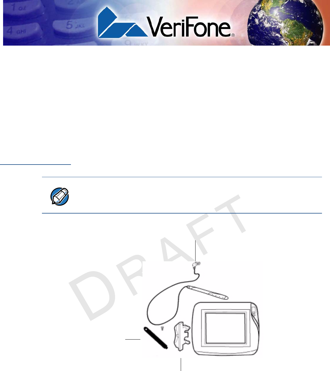
Unpacking the Shipping Carton
Figure 2 Example of Terminal Product Components
NOTE •Inspect the shipping carton and contents for shipping damage (Figure 2). If the Mx800
Series series terminal or any other component appears damaged, immediately file a
claim with the shipping company and notify your terminal provider.
•Do not use a damaged terminal.
CABLE
TIE-DOWN
STRAP AND
SCREW
STYLUS
AND
TETHER
SIDE
MOUNTING
HOLSTER

INSTALLATION
Installing the Device
14 MX800 SERIES INSTALLATION GUIDE
VERIFONE
CONFIDENTIAL
TEMPLATE REV E
Follow these steps to unpack the carton:
1With the shipping carton right side up, open the top and remove all items from
the carton:
•Cable tie-down strap and screw
•Stylus, tether, and mounting holster
2Remove the protective plastic wrap from the display or other components.
3Place the components on a table or countertop.
4Save the shipping carton and packing material for repacking or moving in the
future.
Selecting a Location
1Select a location for the Mx800 Series series terminal convenient for the user
and merchant that offers adequate ventilation and protection.
2Place the Mx800 Series terminal on a flat surface, such as a table or
countertop or mount on a mounting stand supplied by VeriFone. Avoid areas
with:
•Excessive heat or dust
•Oil or moisture
•Devices that cause excessive voltage fluctuations or electrical noise, such
as air conditioners, fans, electric motors, neon signs, or high-frequency
security devices.
•Direct sunlight or objects that radiate heat
3Locate the peripheral conveniently in relation to power and ECR or LAN
connections. The power pack cable is approximately 1.8 meters (6 feet) long.
4Before connecting the terminal to the power supply, complete the installation
by connecting all the cables (see Connecting the Device and Power Up with
the Multiport Cable).
WARNING
The Mx800 Series terminal is designed for indoor use only.
WARNING Do not use this product near water, including a bathtub, wash bowl, kitchen sink,
or laundry tub. Do not use in a wet basement or near a swimming pool.
INSTALLATION
Installing the Device
MX800 SERIES INSTALLATION GUIDE 15
VERIFONE
CONFIDENTIAL
TEMPLATE REV E
Installing
Countertop Wedge
The countertop wedge raises the rear by 10% angle of the Mx800 Series series
terminal to make easy use of the display (Figure 3).
Figure 3 Countertop Wedge: Rear View of the Mx800 Series terminal
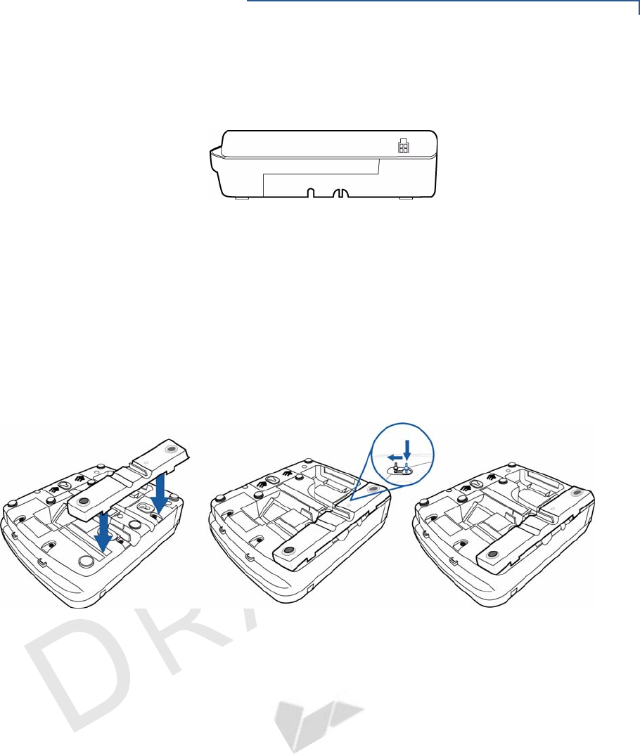
To install the countertop wedge:
1Align the pins in the countertop wedge with the two key holes on the bottom of
the Mx800 Series series terminal (Figure 4).
2Slide the countertop wedge firmly into position.
3Route the multiport cable through the races in the countertop wedge or
through the races underneath the wedge.
Figure 4 Installing the Countertop Wedge of Mx800 Series Series
INSTALLATION
Installing the Device
16 MX800 SERIES INSTALLATION GUIDE
VERIFONE
CONFIDENTIAL
TEMPLATE REV E
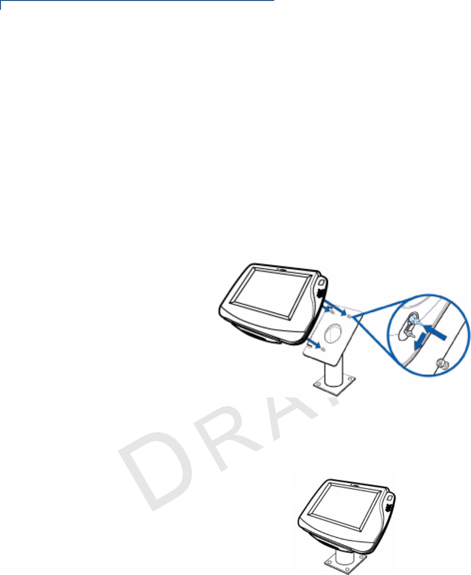
Stand Mount
In most retail spaces, the Mx800 Series terminal is mounted on a stand mount. To
stand mount the Mx800 Series series terminal:
1Install the stand mount on the countertop in the desired lane over an
appropriate hole to thread the wiring connections through.
2Thread all wiring connections through the center of the stand mount.
3Make all wiring connections.
4Attach cable tie-down strap with the supplied screw.
5Align and seat the three pins on the top plate of the stand mount platform with
the three key-hole slots on the bottom of the Mx800 Series terminal (Figure 5).
Figure 5 Aligning Mx800 Series Terminal with the Typical Mounting
Plate.
6Slide the Mx800 Series terminal down until the unit seats securely (Figure 6).
Figure 6 Mx800 Series Terminal mounted.
INSTALLATION
Installing Optional Modules
MX800 SERIES INSTALLATION GUIDE 17
VERIFONE
CONFIDENTIAL
TEMPLATE REV E
Installing
Optional
Modules
This section presents installation procedures for the Mx800 Series terminal’s
optional modules. The Mx800 Series terminal model you have, may already have
some of these options. Modules can be installed at the factory or in the field.
Installing Smart
Card Modules
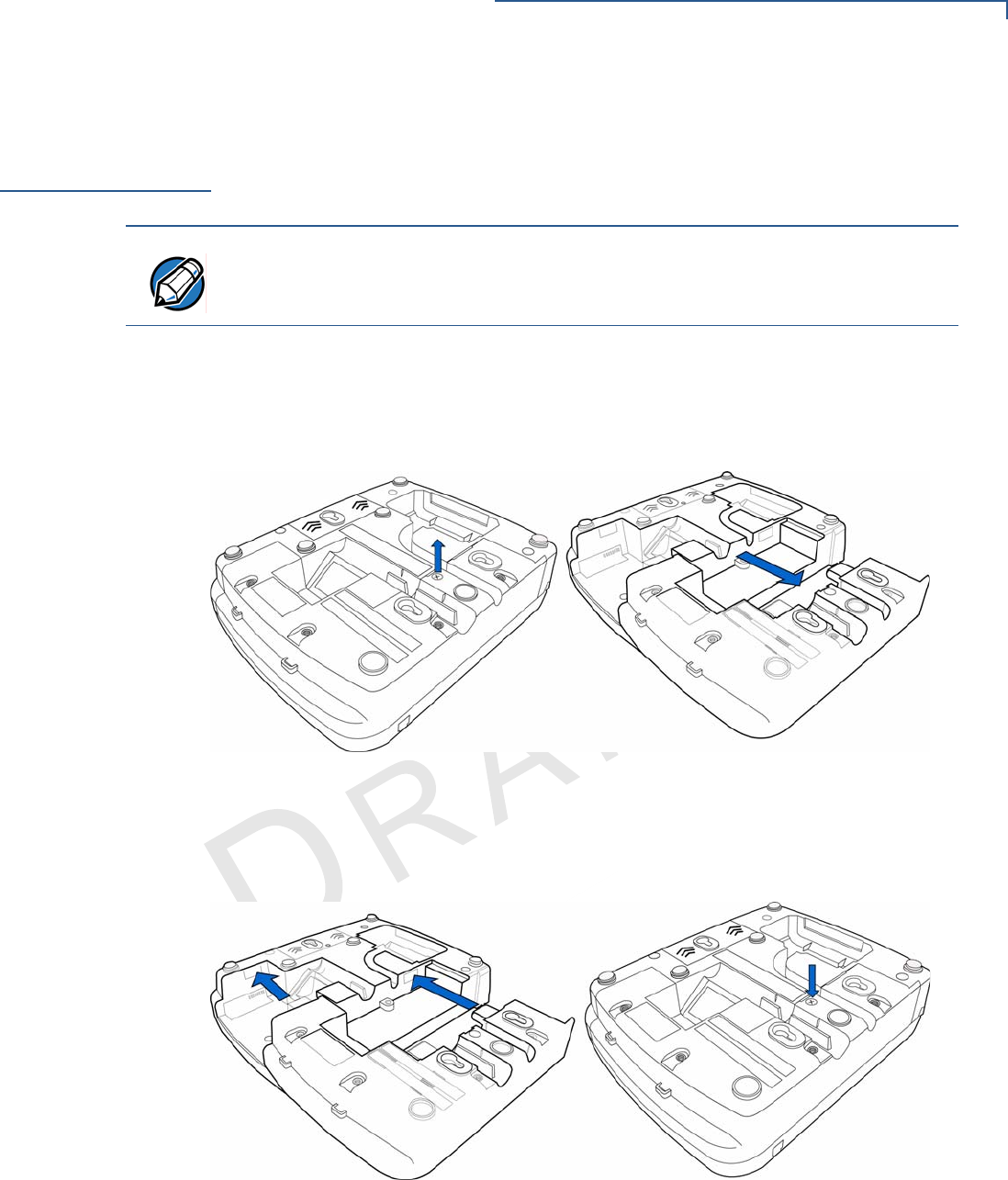
The following are the steps required to install optional I/O modules:
1Loosen the module retaining screw on the bottom of the Mx800 Series (Figure
7) until the old module can slide out.
Figure 7 Removing the Old I/O Module
2Slide the smart card module into place (Figure 8) and secure the retaining
screw.
Figure 8 Installing the Smart Card Module
NOTE The retaining screws are captive, which means they do not actually separate
from their seats, but only from the mounting hole.

INSTALLATION
Installing SAM Cards – Additional Steps
18 MX800 SERIES INSTALLATION GUIDE
VERIFONE
CONFIDENTIAL
TEMPLATE REV E
Installing SAM
Cards –
Additional Steps
The following are the additional steps required to install SAM cards once the first
two steps of installation is completed.
Often merchants are issued SAM cards to run small applications, such as loyalty
programs. SAM cards are only used with Mx800 Series terminal Smart Card
configurations.
1Remove the power cord and/or battery from the terminal.
2Place the terminal upside down on a soft, clean surface to protect the lens
from scratches.
3Remove the SAM compartment door screw and rotate the door up and back to
access the SAM cardholders.
4Remove any previously installed SAM card by sliding the card from the MSAM
cardholder.
5Install an MSAM card by aligning the card and carefully sliding it within the
guides on the cover until it is fully inserted.
Installing Trim
Plate
The Mx800 Series terminal can be fitted with interchangeable trim plates to
customize the appearance of the terminal.
1Insert the trim plate by lining up the three notches of the face plate into the
unit.
2Firmly snap the top part of the trim plate to secure the new trim plate.
Figure 9 Installing the trim plate.
NOTE Before inserting the SAM card, position it with the card’s gold contacts facing the
smart car reader end of the terminal. The cardholder connector base has a set of
contacts and a notch on one corner to ensure the SAM card is positioned correctly.
The SAM card has a notch on one corner to ensure that it fits into the connector
base in only one way. The SAM compartment door will not close properly if the
SAM cards are installed incorrectly.
INSTALLATION
Connecting the Device
MX800 SERIES INSTALLATION GUIDE 19
VERIFONE
CONFIDENTIAL
TEMPLATE REV E
Connecting the
Device
Brief descriptions of possible Mx800 Series terminal device connections and the
power pack connection are provided in this section. For complete information
about installing and using an optional device, refer to the user documentation
supplied with that device. For a list of compatible cables for these connections,
see Accessories.
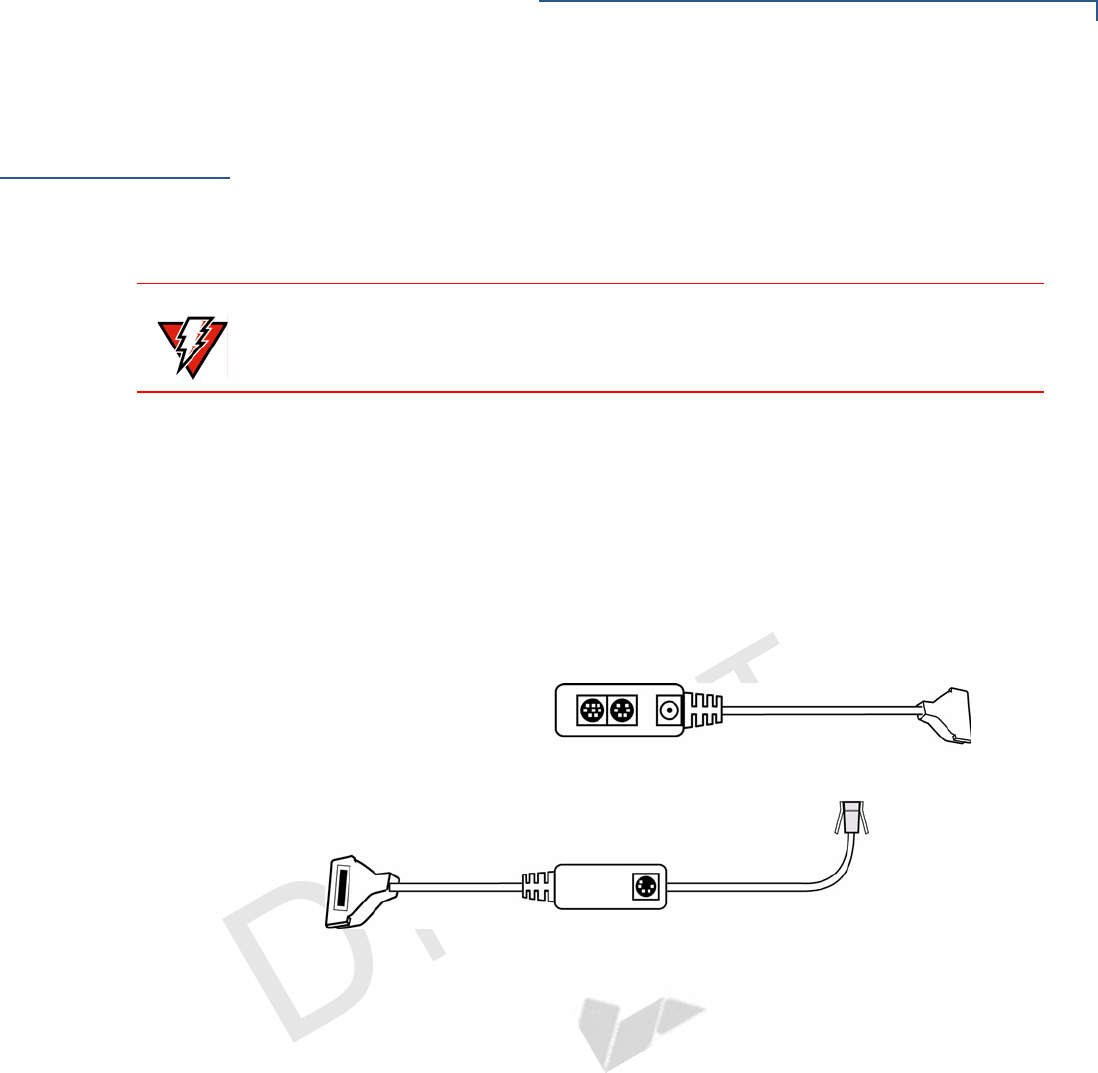
Multiport Cable
The Mx800 Series terminal uses a multiport cable (Figure 10) to make most
connections, including connections to
•an ECR,
•an RS-485 LAN, or
•a development/host PC.
Ethernet LAN and USB connections are made using the Installing Optional
Modules option.
Figure 10 Multiport Cable: Front and Rear
Disconnecting
Multiport
The following are the precautions taken at the time of disconnecting the Multiport:
•Improper installation or removal of the terminal connector may
permanently damage the Mx800 Series.
•Do not force the terminal connector into place.
•Always make sure all of the pins are lined up in correct parallel fashion
before applying light pressure to snap the terminal connector into place.
•Do not attempt to remove the terminal connector by pulling directly on the
cable. Instead, firmly grasp the sides of the terminal connector with thumb
and forefinger, then pull straight away at the same angle the connector on
the terminal is facing.
•Disconnecting the power source during transaction processing may cause
loss of transaction data.
WARNING Before connecting the Mx800 Series terminal, ensure all units are not connected
to a power source. Unplug all power packs from the wall jack.
INSTALLATION
Connecting the Device
20 MX800 SERIES INSTALLATION GUIDE
VERIFONE
CONFIDENTIAL
TEMPLATE REV E
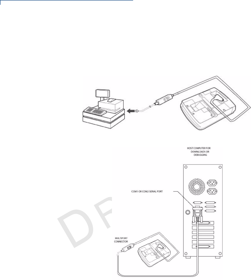
Connecting ECR in
Tailgate Mode
To connect an ECR to the Mx800 Series terminal (see Figure 11):
1Insert the multiport cable into the rear of the ECR.
2Insert the multiport cable plug into the bottom socket on the Mx800 Series
terminal, as shown in Figure 11.
Figure 11 Example ECR Connection
Connecting to a
Host PC
To connect the Mx800 Series terminal to a development PC. See Figure 12
Figure 12 Host PC Connection
INSTALLATION
Power Up with the Multiport Cable
MX800 SERIES INSTALLATION GUIDE 21
VERIFONE
CONFIDENTIAL
TEMPLATE REV E
Connecting to the
Ethernet LAN
To connect the Mx800 Series terminal to an Ethernet LAN through the 10BaseT
port, using a standard Ethernet cable, insert the LAN cable from the LAN router or
hub into the 10Base-T port on the bottom of the Mx800 Series terminal.
Connecting to USB
Host or Hub
Connecting to a USB host or hub requires a VeriFone USB cable (VPN 22982-xx).
To connect to a USB host or hub:
1Insert the modular plug on the USB cable into the USB jack.
2Route the cable through the slots to the desired exit side.
3Plug the other end of the USB cable into the USB host or hub.
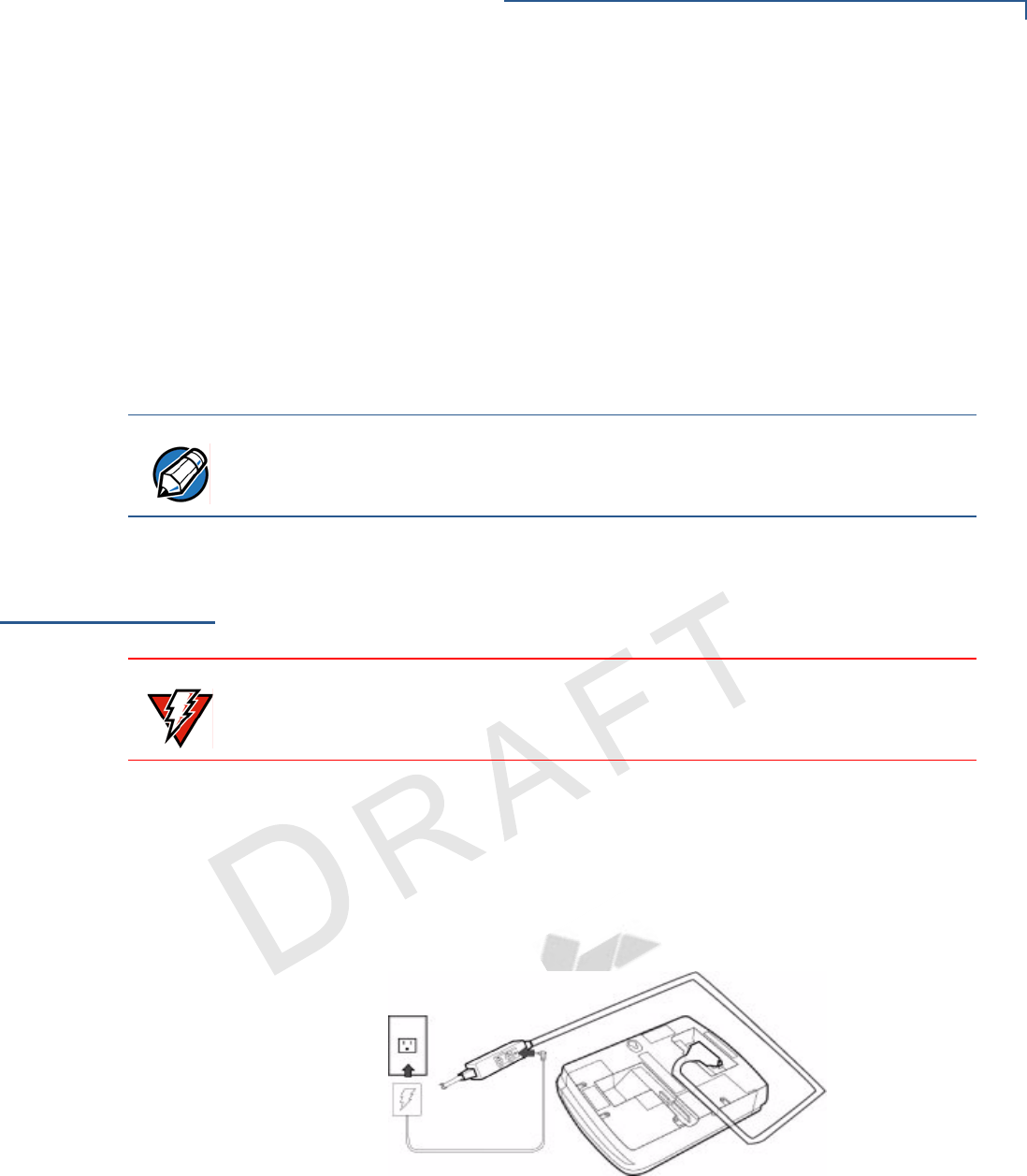
Power Up with
the Multiport
Cable
This section describes how to connect the Mx800 Series terminal to a power
source with the multiport cable.
If connected to an ECR, the Mx800 Series terminal gets power from the ECR.
1Make all other connections before connecting the power pack.
2Insert the multiport cable connector into the port on the back of the Mx800
Series terminal (see Figure 13).
3Route the cable through the slots to the desired exit side.
4Plug the power pack into an indoor electrical power outlet (Figure 13).
Figure 13 Power Pack Connection
If no application is installed in the terminal, the message DOWNLOAD NEEDED
displays for a moment, then the main Mx800 Series terminal screen displays. An
application-specific prompt displays when an application executes.
NOTE The Mx800 Series series terminal can be connected to an ECR through the USB
cable. When connected through a USB cable, the Mx800 Series series terminal
gets power through the USB cable and does not require the multiport cable.
WARNING Do not plug the power pack into an outdoor outlet or operate the terminal
outdoors.

INSTALLATION
Power Up without the Multiport Cable
22 MX800 SERIES INSTALLATION GUIDE
VERIFONE
CONFIDENTIAL
TEMPLATE REV E
Power Up
without the
Multiport Cable
This section describes connecting the Mx800 Series terminal to a power source
when no multiport cable is required.
Use the following guidelines when Mx800 Series terminal is connected to power:
1Make all the cable connections before connecting the power cable.
2Insert the modular power connector either into the USB or 10Base-T port,
whichever is available.
3Plug the power pack into an indoor electrical wall outlet.
NOTE If connected to an ECR using a USB cable, the Mx800 Series terminal gets
power from the ECR.

VERIFONE
CONFIDENTIAL
TEMPLATE REV E
MX800 SERIES INSTALLATION GUIDE 23
CHAPTER 3
Maintenance
The Mx800 Series terminal has no user-maintainable parts.
Cleaning the
Terminal
To clean the terminal, use a clean cloth slightly dampened with water and a drop
or two of mild soap. For stubborn stains, use alcohol or an alcohol-based cleaner.
For best results, use a VeriFone Cleaning Kit. For further details refer to 02746-01
VeriFone Cleaning Kit.
Smart Card
Reader
Do not attempt to clean the smart card reader. Doing so may void any warranty.
For smart card reader service, contact your VeriFone distributor or service
provider.
WARNING Never use thinner, trichloroethylene, or ketone-based solvents – they may
deteriorate plastic or rubber parts. Do not spray cleaners or other solutions
directly onto the display.
NOTE The smart card implementation is a proprietary hardware solution that has no
serviceable parts.

MAINTENANCE
Smart Card Reader
24 MX800 SERIES INSTALLATION GUIDE
VERIFONE
CONFIDENTIAL
TEMPLATE REV E

VERIFONE
CONFIDENTIAL
TEMPLATE REV E
MX800 SERIES INSTALLATION GUIDE 25
CHAPTER 4
Troubleshooting
During normal, day-to-day operation of your Mx800 Series series terminal, it is
possible that minor malfunctions can occur. Following are some examples of
possible problems, and steps to resolve them.
VeriFone follows stringent quality control standards in the manufacture of Mx800
Series terminals. Each unit that leaves the factory receives numerous tests to
ensure quality and reliable operation. However, should you encounter a problem
in operation, read this section for possible causes and solutions.
The troubleshooting guidelines provided in this section identify various problems
and suggest appropriate corrective action(s). If you have problems operating your
Mx800 Series terminal, please read through these troubleshooting examples. If
the problem persists or if it is not described below, contact your local VeriFone
representative for assistance.
Blank Display
The following are the corrective steps taken if the terminal display does not show
correct or readable information:
1Check all cable connections.
2If the problem persists, contact your local VeriFone representative for
assistance.
Serial Port Does Not
Work
The following are the corrective steps taken if the serial port does not work:
1Check that the device connected to the serial port of the multiport cable of the
Mx800 Series terminal has power and is functioning correctly. If possible,
perform a self-test on the device.
2The cable connecting the optional device to the Mx800 Series terminal serial
port may be defective. Try a different serial cable.
3If the problem persists, contact your local VeriFone representative for
assistance.
NOTE •Perform only those adjustments or repairs specified in this guide. For all other
services, contact your local VeriFone distributor or service provider. Service
conducted by parties other than authorized VeriFone representatives may
void the product warranty.
•The Mx800 Series terminal comes equipped with tamper-evident labels. Do
not, under any circumstance, attempt to disassemble the terminal.

TROUBLESHOOTING
26 MX800 SERIES INSTALLATION GUIDE
VERIFONE
CONFIDENTIAL
TEMPLATE REV E
Transaction Fail to
Process
The following are the corrective steps taken if the terminal does not process the
transaction:
There are several possible reasons why the terminal may not be operating
correctly or processing transactions. To check the most likely causes, follow the
steps below.
Step 1: Check the
magnetic card reader 1Make sure you are swiping cards correctly with the Mx800 Series terminal.
The Mx800 Series terminal reader, the black magnetic stripe on the card
should face down.
2Perform a test transaction using several different magnetic stripe cards to
ensure the problem is not a defective card.
3Process a transaction manually using the touch screen instead of the card
reader. If the manual transaction works, the problem may be a defective card
reader. Contact your VeriFone distributor or service provider.
4If the manual transaction does not work, proceed to Step 3.
Step 2: Check the
smart card reader 1Make sure you are inserting the cards correctly with the Mx800 Series terminal
smart card reader. The chip on the card should face down and inward.
2Perform a test transaction using several different smart cards to ensure that
the problem is not with the card.
3Ensure any MSAM cards are correctly inserted and the cardholders are
properly secured.
4If the problem persists, contact your VeriFone distributor or service provider.
Step 3: Check the
cable connections 1Ensure that all cables are correctly connected.
If cables are connected properly:
2Check that the cable is in working order by connecting a known good cable. If
transactions process with this cable, replace the bad cable.
3If the problem persists, contact your local VeriFone representative for
assistance.
No Response From
the Stylus
The following are the corrective steps taken if the terminal does not respond to the
stylus inputs:
1Check the documentation to ensure that the terminal supports stylus.
2Unplug the stylus that does not respond and connect a known working stylus.
3If the problem persists, contact your local VeriFone representative for
assistance.
Gap in Captured
Signature
The following are the corrective steps taken if there is a gap in captured signature:
1Ensure that the stylus is pressed hard during signature capture.

TROUBLESHOOTING
MX800 SERIES INSTALLATION GUIDE 27
VERIFONE
CONFIDENTIAL
TEMPLATE REV E
2If the problem persists, contact your local VeriFone representative for
assistance.
No Response From
the Touch Panel
The following are the corrective steps taken if the Touch Panel does not respond
or gives an incorrect response.
1Make sure you power off and power on.
2If the problem persists, contact your local VeriFone representative for
assistance.
NOTE
Keep your hands away from the touch panel while terminal powers up.

TROUBLESHOOTING
28 MX800 SERIES INSTALLATION GUIDE
VERIFONE
CONFIDENTIAL
TEMPLATE REV E
VERIFONE
CONFIDENTIAL
TEMPLATE REV E
MX800 SERIES INSTALLATION GUIDE 29
CHAPTER 5
VeriFone Service and Support
For Mx800 Series terminal problems, contact your local VeriFone representative
or service provider.
For Mx800 Series product service and repair information:
•USA – VeriFone Service and Support Group, 1-800-834-9133,
Monday - Friday, 8 A.M. - 7 P.M., EST
•International – Contact your VeriFone representative.
Return a
Terminal for
Service
Before returning the Mx800 Series terminal to VeriFone, obtain a Merchandise
Return Authorization (MRA) number. The following procedure describes how to
return one or more Mx800 Series Series terminals for repair or replacement (U.S.
customers only).
1Gather the following information from the printed labels (see Figure 14) on the
bottom of each Mx800 Series terminal to be returned:
•Product ID, including the model and part number.
•Serial number (S/N xxx-xxx-xxx)
2Within the United States, call VeriFone toll-free at 1-800-834-9133.
3Select the MRA option from the automated message. The MRA department is
open Monday–Friday, 8 A.M.–7 P.M., EST.
NOTE For International customers, please contact your local VeriFone representative
for assistance with your service, return, or replacement.
WARNING Do not, under any circumstances, attempt any service, adjustments, or repairs on
this equipment, other than the simple cleaning processes discussed in Chapter 3.
Instead, contact your local VeriFone distributor or service provider for assistance.
Failure to comply can invalidate the product warranty.
WARNING This terminal comes equipped with a tamper-evident label. This Tamper Warning
label covers a screw hole on the case bottom and indicates if an unauthorized
party has opened the terminal case. Opening the case will make the terminal
inoperable and void the product warranty!

VERIFONE SERVICE AND SUPPORT
Return a Terminal for Service
30 MX800 SERIES INSTALLATION GUIDE
VERIFONE
CONFIDENTIAL
TEMPLATE REV E
4Give the MRA representative the information gathered in step 1.
If the list of serial numbers is long, fax the list, along with the information
gathered in step 1, to the MRA department at 727-953-4172.
•Please address the fax clearly to the attention of the “VeriFone MRA
Dept.”
•Include a telephone number where you can be reached, as well as your
fax number.
•You will be issued MRA number(s) and the fax will be returned to you.
5Describe the problem(s).
6Provide the shipping address where the repaired or replacement unit must be
returned.
7Keep a record of the following items:
•Assigned MRA number(s).
•VeriFone serial number assigned to the Mx800 Series terminal you are
returning for service or repair (terminal serial numbers are located on the
bottom of the unit (see Figure 14).
•Shipping documentation, such as air bill numbers used to trace the
shipment.
NOTE One MRA number must be issued for each Mx800 Series terminal returned to
VeriFone, even if you are returning the same model several times.

VERIFONE SERVICE AND SUPPORT
Accessories
MX800 SERIES INSTALLATION GUIDE 31
VERIFONE
CONFIDENTIAL
TEMPLATE REV E
•Model(s) returned (model numbers are located on the VeriFone label on
the bottom of the Mx800 Series terminal).
NEEDS UPDATED IMAGE
Figure 14 Product Information Labels
Accessories
Accessories for the Mx800 Series are listed below. When ordering, please refer to
the part number in the left column.
Optional I/O
Modules
Optional
Accessories
Cables
XX in part numbers indicates different cable lengths, as follows:
TBD
TBD Ethernet
22647-XX (TBD) Trim Plate
22648-01 (TBD) Privacy Shield
22967-01 (TBD) Countertop wedge
23294-01 (TBD) Privacy shield
23323-01 (TBD) Stylus
XX = Length Metric Length Feet
00 0.36 m 1.2’
01 1.0 m 3.3’
02 2.0 m 6.6’
03 3.0 m 9.8’
05 5.0 m 16.4’
VERIFONE SERVICE AND SUPPORT
Accessories
32 MX800 SERIES INSTALLATION GUIDE
VERIFONE
CONFIDENTIAL
TEMPLATE REV E
Mx800 Series Terminal Cables
Mini-DIN Style Multiport Cables
Additional Cables
Table 4 Multiport Cable
Part Number Description
TBD Red
TBD Green
TBD Blue
TBD Black
Table 5
13984-XX 1 6/8-pin mini-DIN serial port and 2 ECR tailgates; flying lead to
connect to ECR
17820-XX 2 serial port; 1 ECR port
17881-XX 2 serial ports; flying lead to connect to ECR
17882-XX 1 serial port and 1 5-pin LAN port; flying lead to connect to ECR
17883-XX 2 serial ports; RJ11 flying lead to connect to LAN
17884-XX 3 serial ports; no flying lead
17885-XX 3 serial ports; D89F serial port flying lead to connect to PC
NOTE Use standard Ethernet cables (MOD8-MOD8) to complete the 10Base-T
connection.
00124-03 Telco cable; Mx800 Series to RJ11 phone jack
05602-00 RJ45-DB9; Mx800 Series to PC AT
07042-XX RJ45-RJ11; Mx800 Series to PINPad
22089-XX RJ45-SDL8; Mx800 Series to IBM ECR 46xx (port 5A)
22090-XX RJ45-SDL4; Mx800 Series to IBM 46xx ECR (SDL4 port)
22091-XX RJ45-8-pin Mini DIN; Mx800 Series to printer 250, 900, or 355
22092-XX RJ45-RJ45; Mx800 Series to VeriFone terminal
22093-XX RJ45-SDL8; Mx800 Series to IBM ECR 46xx (port 5B)
22172-XX RJ45-SDL8; Mx800 Series to IBM ECR keyboard (SDL8 port)
22982-XX Mx800 Series USB to PC USB

VERIFONE SERVICE AND SUPPORT
Accessories
MX800 SERIES INSTALLATION GUIDE 33
VERIFONE
CONFIDENTIAL
TEMPLATE REV E
Documentation
When ordering, please refer to the part number in the left column.
Support Packages
When ordering, please refer to the part number in the left column.
22934 Omni 7000MPD Quick Installation Guide
22936 Omni 7000MPD Signature Capture/Touch Screen Module Quick Installation
Guide
23255 Omni 7100MPD Quick Installation Guide
23432 Omni 7xxx Series Programmers Guide
23433 Omni 7xxx Series Reference Manual
23434 Omni 7xxx Series I/O Module Quick Installation Guide
P006-277-xx-MK Mx800 Series Programmers Support Package Kit
P006-278-xx-MK Mx800 Series Programmers Support Package Kit

VERIFONE SERVICE AND SUPPORT
Accessories
34 MX800 SERIES INSTALLATION GUIDE
VERIFONE
CONFIDENTIAL
TEMPLATE REV E
VERIFONE
CONFIDENTIAL
TEMPLATE REV E
MX800 SERIES INSTALLATION GUIDE 35
CHAPTER 6
Specifications
M
x
800 Series
Terminal
Specifications
Shipping weight: 1.08 kg (2.38 lb); includes terminal, cable tie down strap and
screw, and quick installation guide.
Table 6 Mx800 Series Terminal Specifications
Power •Peripheral power requirements: DC power pack: 12 V DC at
1.0 A
•Power pack requirements:120 V AC at 60 Hz (U.S.)
Environmental •Operating temperature: 0° to 40° C (32° to 104° F)
•Storage temperature: – 18° to + 66° C (0° to 150° F)
•Humidity: 15% to 95% relative humidity; no condensation
Dimensions Base Unit
•Height: 153 mm (6.0 inches)
•Width: 192 mm (7.5 inches)
•Depth: 52 mm (2 inches)
Weight •Terminal weight: 0.71 kg (1.56 lb)

SPECIFICATIONS
Mx800 Series Terminal Specifications
36 MX800 SERIES INSTALLATION GUIDE
VERIFONE
CONFIDENTIAL
TEMPLATE REV E

MX800 SERIES INSTALLATION GUIDE A
VERIFONE
CONFIDENTIAL
TEMPLATE REV E
INDEX
A
Accessories
Optional 31
Optional I/O Modules 31
Applications 10
C
connecting
ECR in Tailgate mode 20
Ethernet LAN
Ethernet LAN 21
Host PC 20
hub 21
multiport cable
multiport cable 19
USB host 21
D
disconnecting
multiport cable
multiport cable 19
display
troubleshooting 25
E
ECR
Tailgate mode 20
Ethernet 9
F
Factory Options 9
factory options
ethernet/USB module 9
polarized screen 9
smart card module 9
speakers 9
Features 7
Mx800 Series 7
Spectrum Mx800 Series 8
I
installation
unpacking 13
installing
countertop wedge 15
optional modules 17
SAM cards 18
selecting a location 14
smart card modules 17
stand mount 16
trim plate 18
M
maintenance 23
cleaning the terminal 23
returning a terminal for repair or replacement 29
smart card reader 23
multiport cable
power up 22
Mx800 Series
features and benefits 8
maintenance 23
overview 7
O
Optional Accessories
Cables 31
Optional Modules 9
Contactless Reader Module 10
optional modules 10
privacy shield 10
signature capture 10
smart card 17
S
SAM cards
additional steps 18
service
returning a terminal for repair or replacement 29
Service and Support 29
Specifications


INDEX
MX800 SERIES INSTALLATION GUIDE C
VERIFONE
CONFIDENTIAL
TEMPLATE REV E