Verifone OMNI3600D Point of Sale Terminal User Manual
VeriFone Inc Point of Sale Terminal
Verifone >
Contents
- 1. User Manual Part I
- 2. User Manual Part II
- 3. User Manual Part III
- 4. User Manual Part IV
- 5. User Manual Part V
User Manual Part II
OMNI 3600 TERMINAL AND OMNI 3600 BASE INSTALLATION
Omni 3600 Terminal
16 OMNI 3600 REFERENCE MANUAL
Printer Test
To ensure the printer is operating correctly:
1Turn on the terminal by pressing the green enter key (see Figure 2, page 10).
2Enter system mode by pressing F2+F4 at the initial copyright screen, and
entering the system mode password (see Passwords).
3Toggle through the screens, using the down arrow key until you
reach .
4Press F4 to enter the screen.
5Press F3, , to start the printer self-test.
The test printout, with printer information and repeating character strings, is
approximately 38 cm (15 in.) long.
Install/Replace
MSAM Cards
When you first receive your Omni 3600 terminal, you may need to install a
merchant smart card or one or more micromodule-sized security account
manager (MSAM) cards, or you may need to replace old cards. Often, these small
cards arrive on a larger, credit card-style plastic card, from which they must be
removed. The following procedure describes MSAM card installation.
1Remove the battery (see Smart Battery)
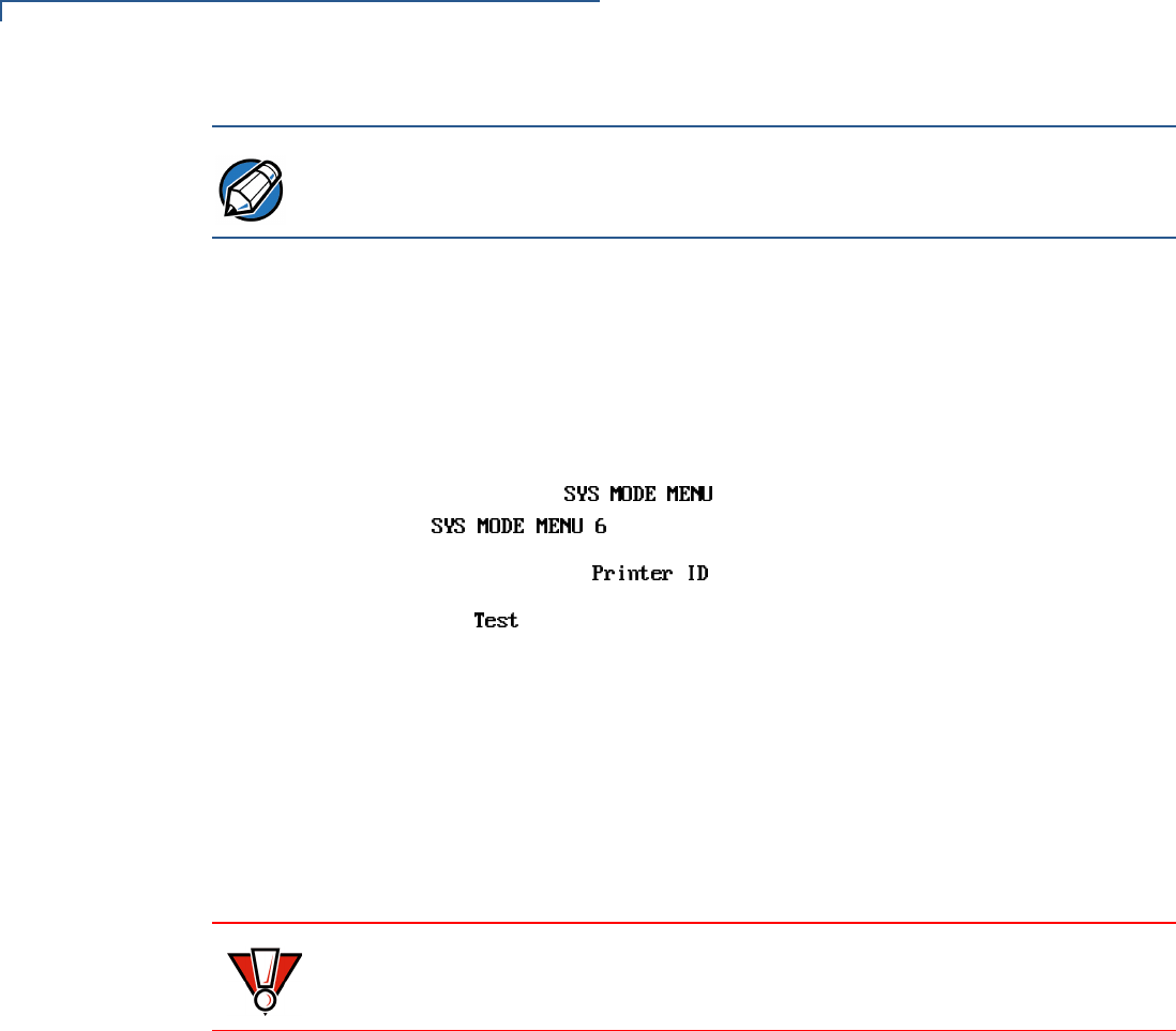
2Open the MSAM door located beneath the battery (Figure 9):
aPush down and back on the raised arrow on the door.
bLift up on the raised arrow with the tip of your index finger.
cOpen the door until it is in the upright position, resting against the end of
the terminal.
NOTE To prevent damage to the print roller on the paper roll cover, always close the
cover by gently pressing down on the paper roll cover tab.
CAUTION Observe standard precautions for handling electrostatically sensitive devices.
Electrostatic discharges can damage this equipment. An anti-static wrist strap
grounded to a metal surface is recommended.
OMNI 3600 TERMINAL AND OMNI 3600 BASE INSTALLATION
Omni 3600 Terminal
OMNI 3600 REFERENCE MANUAL 17
Figure 9 Open the MSAM Access Door
The three MSAM cardholders are now accessible. Each cardholder consists of
a hinged tilt-up cover attached to a connector base (Figure 10).
Figure 10 MSAM Card Installation
3Access the MSAM cardholders (reference Figure 10):
aUnlock the cardholder: Slide the lock plate to the unlocked position, in the
OPEN direction (Figure 11).
Figure 11 MSAM Cardholder Lock Plate Detail
OMNI 3600 TERMINAL AND OMNI 3600 BASE INSTALLATION
Omni 3600 Terminal
18 OMNI 3600 REFERENCE MANUAL
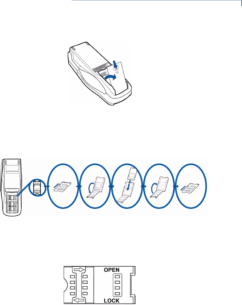
bOpen the cardholder by pivoting the cover on its hinge away from the
connector base (Figure 12).
Figure 12 Insert MSAM Card into Cardholder
4Remove any previously installed MSAM card by sliding the card from the
cover.
5Install an MSAM card by aligning the card and carefully sliding it within the
guides on the cover until fully inserted.
6Close the cover (Figure 12).
7Lock each MSAM cardholder by sliding its locking plate towards the LOCK
arrow until the plate stops (Figure 11).
8Close the MSAM door.
9Replace the smart battery.
Install/Replace
SIM Card (GSM
models)
The SIM (Subscriber Identity Module) card is a smart card inserted in the
Omni 3600 GSM terminal that contains your GSM radio account information. Use
the following procedure to replace or install a SIM card.
NOTE The cardholder has a set of contacts and a notch on one corner to ensure the
MSAM card is positioned correctly when the cover is closed. The MSAM card has
a notch on one corner to ensure it is correctly positioned in the cardholder. Before
inserting the MSAM card, position it as shown in Figure 12.
CAUTION To avoid damage to the MSAM cardholders, ensure each cardholder is locked
before closing the MSAM door.
OMNI 3600 TERMINAL AND OMNI 3600 BASE INSTALLATION
Omni 3600 Terminal
OMNI 3600 REFERENCE MANUAL 19
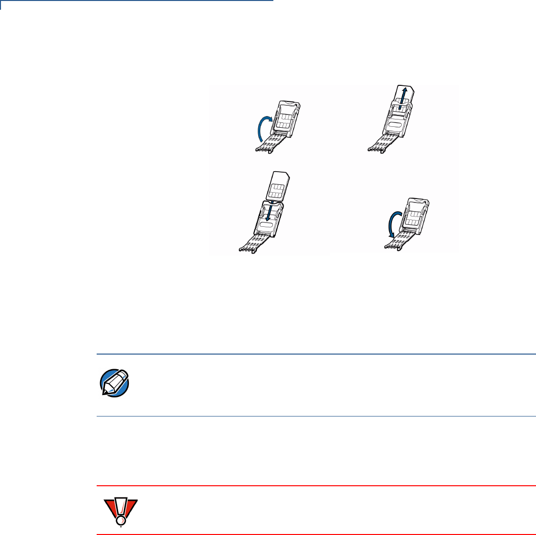
1Remove screw from SIM card access door on back of Omni 3600 terminal
(Figure 13).
Figure 13 Remove SIM Door Screw
2Remove the SIM card access door (Figure 14):
Figure 14 Slide Off SIM Card Access Door
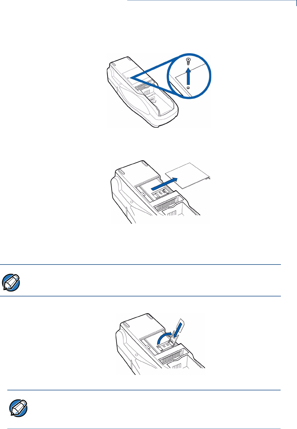
3Open the SIM card holder and slide the SIM card supplied by your provider
into the cardholder (Figure 15).
Figure 15 Insert SIM Card into Cardholder
4Replace the SIM card access door and screw.
NOTE
Do not lose the SIM card dust cover or retaining screw.
NOTE The SIM cardholder has a notch on one corner to ensure the SIM card is
positioned correctly. The SIM card has a notch on one corner for easy orientation
in the cardholder. Before inserting the SIM card, position it as shown in Figure 15,
with the card’s gold contacts facing down.
OMNI 3600 TERMINAL AND OMNI 3600 BASE INSTALLATION
Omni 3600 Terminal
20 OMNI 3600 REFERENCE MANUAL
Wireless
Transactions
To conduct a wireless transaction:
•Ensure the terminal is in an optimal position for transmitting.
•Follow the on-screen instructions provided with your application.
Smart Card Reader
Transactions
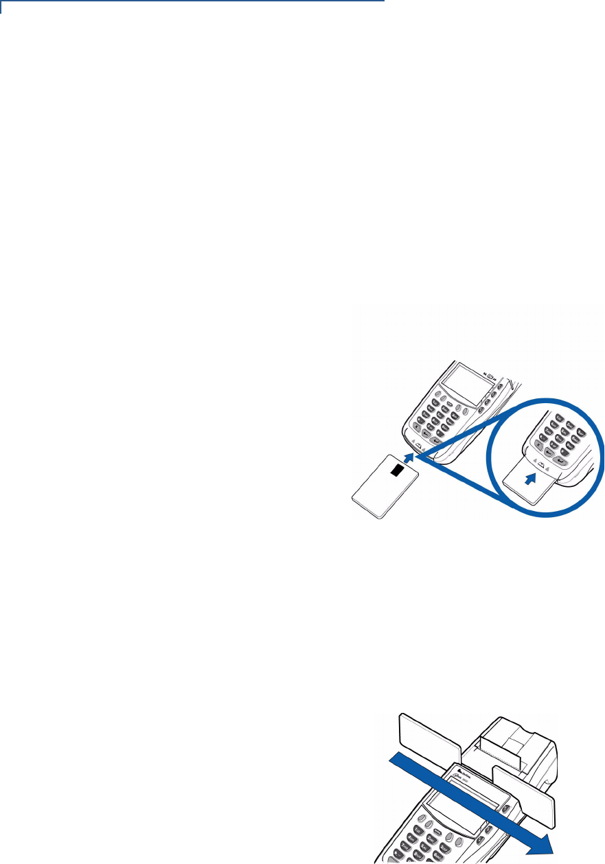
To conduct a smart card transaction:
1Position the smart card with the contacts up and insert it into the smart card
reader slot in a smooth, continuous motion until it seats firmly (Figure 16).
Leave the smart card in the card reader until the transaction is complete.
Premature removal voids the transaction.
Figure 16 Using the Primary Smart Card Reader
2Remove the card when the display indicates the transaction is complete.
Magnetic Card
Reader
Transactions
To conduct a credit/debit card transaction:
1Position the card with the magnetic stripe facing down and towards the printer.
2Swipe it through the reader from left-to-right, as shown in Figure 17.
Figure 17 Using the Magnetic Card Reader
OMNI 3600 TERMINAL AND OMNI 3600 BASE INSTALLATION
Omni 3600 Terminal
OMNI 3600 REFERENCE MANUAL 21
Antenna (Some
Wireless Models)
For some Omni 3600 terminals to establish a wireless connection, an external
antenna is provided. This connection allows communication with your service
provider to upload transaction data from the terminal and download system
upgrades to the terminal. Radio service is activated by your service provider.
Data transfers can also be performed through the Omni 3600 base (see
Omni 3600 Base Communications Ports).
This section only discusses Omni 3600 terminals with external antenna.
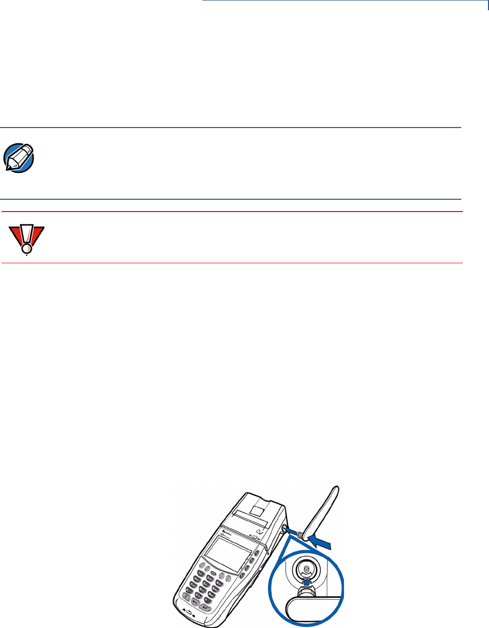
Installation
The Omni 3600 should arrive from manufacture with the antenna attached. If
unattached, use the following procedure to install the antenna:
1Locate the antenna port on the side of the Omni 3600 terminal.
2Align the respective “notch” inside the antenna to the key in the terminal
(Figure 18).
3Push gently on the center of the base of the antenna until it locks in position.
Figure 18 Antenna Installation
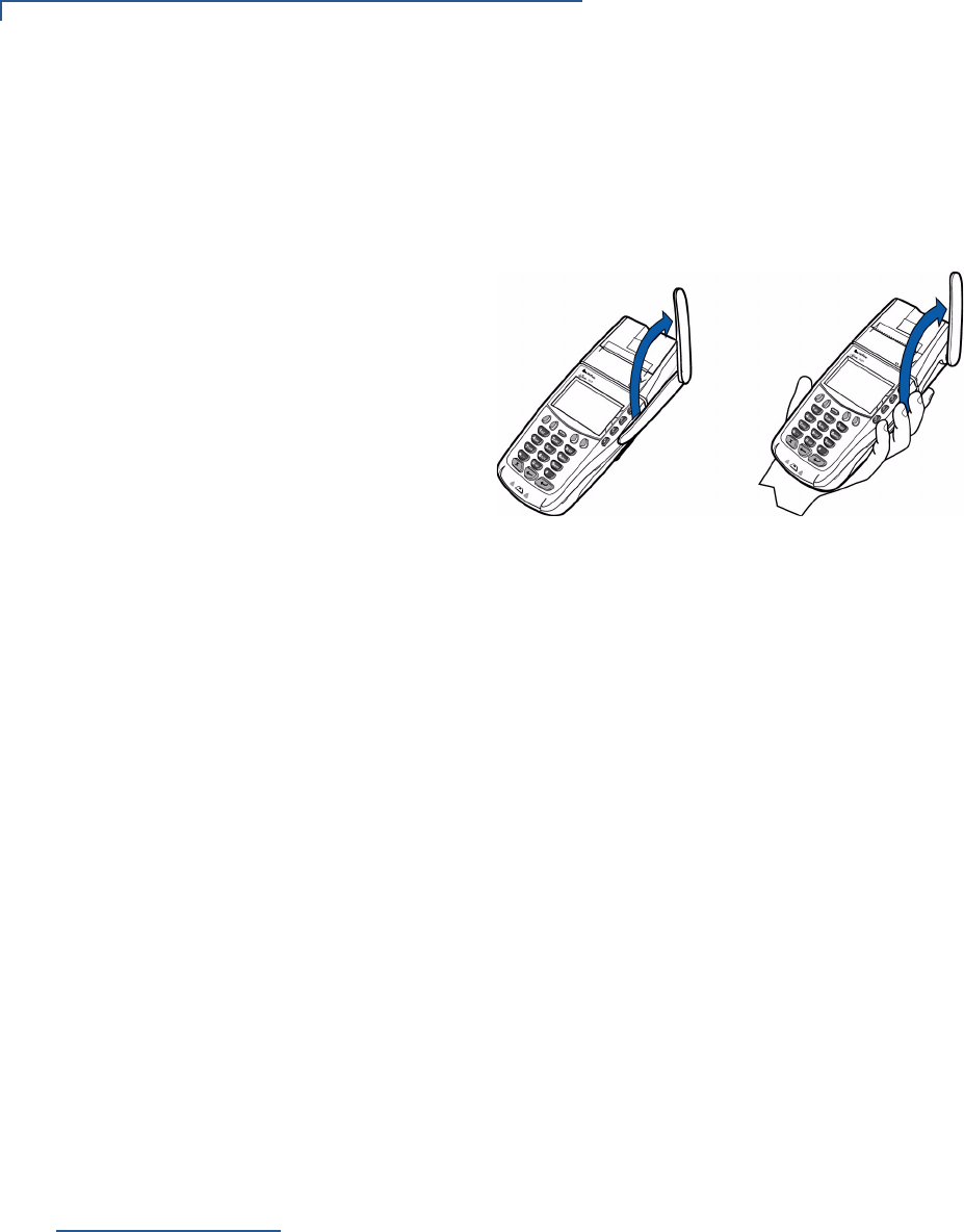
Orientation
To establish good wireless communication (uplink), it is important that the antenna
always be vertically aligned with respect to ground and sky (Figure 19). For
example, if standing and holding the terminal horizontally, position the antenna at
an approximately 90° angle to the unit (that is, pointing up from the printer). This
should point the antenna directly at the sky.
NOTE Most Omni 3600 terminals have an internal antenna and this section can be
ignored.
Only use the antenna designed for your unit. Failure to use the proper antenna
results in the inability to establish a wireless connection.
CAUTION Never hold the unit by the antenna; doing so may break the connection and void
your warranty.
OMNI 3600 TERMINAL AND OMNI 3600 BASE INSTALLATION
Omni 3600 Base
22 OMNI 3600 REFERENCE MANUAL
If the unit is on a flat surface (for example, a table top) or docked in the Omni 3600
base, position the antenna so that it points directly at the sky. Soft detentes are
felt and clicks heard when positioning the antenna. These detentes maintain
antenna positions of 60°, 90°, and 180°.
Figure 19 Correct Antenna Position for Uplink
If an application (for example, SoftPay) is installed in your Omni 3600 unit, a
signal strength indicator may appear on the display.
Replace the Antenna
If your Omni 3600 terminal has difficulties completing wireless transactions, you
may have to replace the antenna. Use the following procedure to replace the
antenna:
1Remove the existing antenna from the Omni 3600 terminal:
aRotate the antenna to align with the base of the unit, pointing away from
the back.
bGrasp the base of the antenna, close to the body of the terminal.
cPull gently out until the antenna unsnaps from the antenna port.
2Align the respective notch inside the new antenna to the key in the antenna
port on the terminal (Figure 18).
3Push gently on the center of the base of the newly installed antenna until it
locks in position.
Omni 3600
Base
This section discusses the features of the Omni 3600 base, including
•providing power to the Omni 3600 base,
•docking the Omni 3600 terminal,
•charging the smart battery in a docked terminal,
•charging a spare smart battery,
•establishing communications, and
•connecting peripheral devices.
The Omni 3600 base does not support PIN pad connections.
OMNI 3600 TERMINAL AND OMNI 3600 BASE INSTALLATION
Omni 3600 Base
OMNI 3600 REFERENCE MANUAL 23
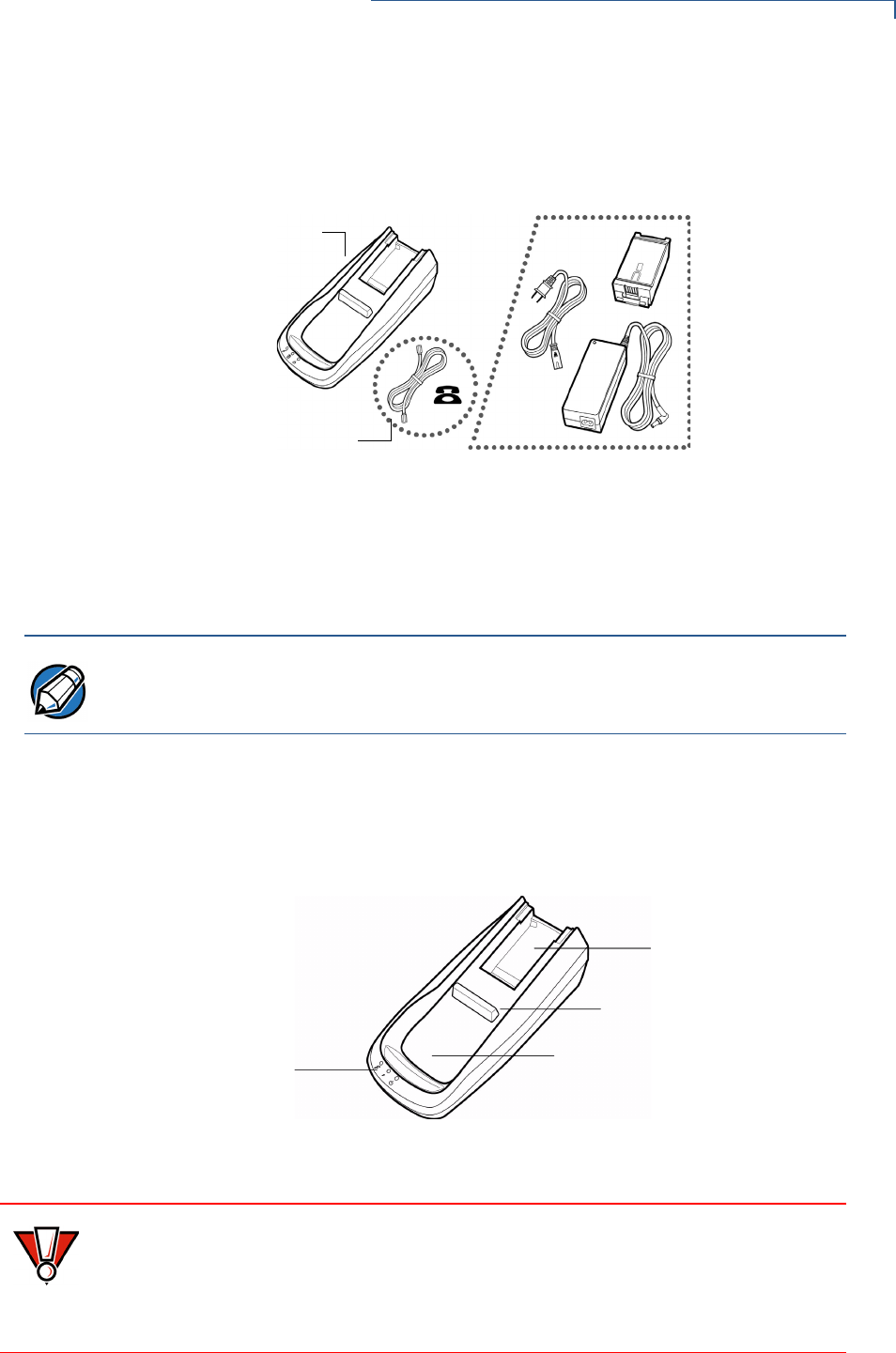
Unpack the
Shipping Carton
Refer to Figure 20 and the following procedure while unpacking the Omni 3600
base shipping carton.
Figure 20 Omni 3600 Base Shipping Carton Contents
1Remove the following items:
•Omni 3600 base
•Telco cable (optional)
2Remove all plastic wrap from the Omni 3600 base and other components.
Omni 3600 Base
Features
This section discusses the features of the Omni 3600 base.
Figure 21 Omni 3600 Base Features: Top
OMNI 3600
BASE
TELCO CABLE
(OPTIONAL)
OPTIONAL ACCESSORIES
NOTE The power pack and power cable, spare battery packs, and Telco cable are
available separately. See Accessories and Documentation for ordering
information.
STATUS LEDS
SPARE BATTERY
DOCK
TERMINAL DOCKING
CONTACTS
TERMINAL DOCKING
CRADLE
CAUTION Avoid touching the contacts in the raised area in the center of the Omni 3600
base. Finger oils tarnish contacts, causing bad connections. If the battery charge
state or terminal power LEDs do not light when the terminal is docked, or there is
a high occurrence of bad or incomplete data transfers, clean the contacts. See
Maintenance for more information.
OMNI 3600 TERMINAL AND OMNI 3600 BASE INSTALLATION
Omni 3600 Base
24 OMNI 3600 REFERENCE MANUAL
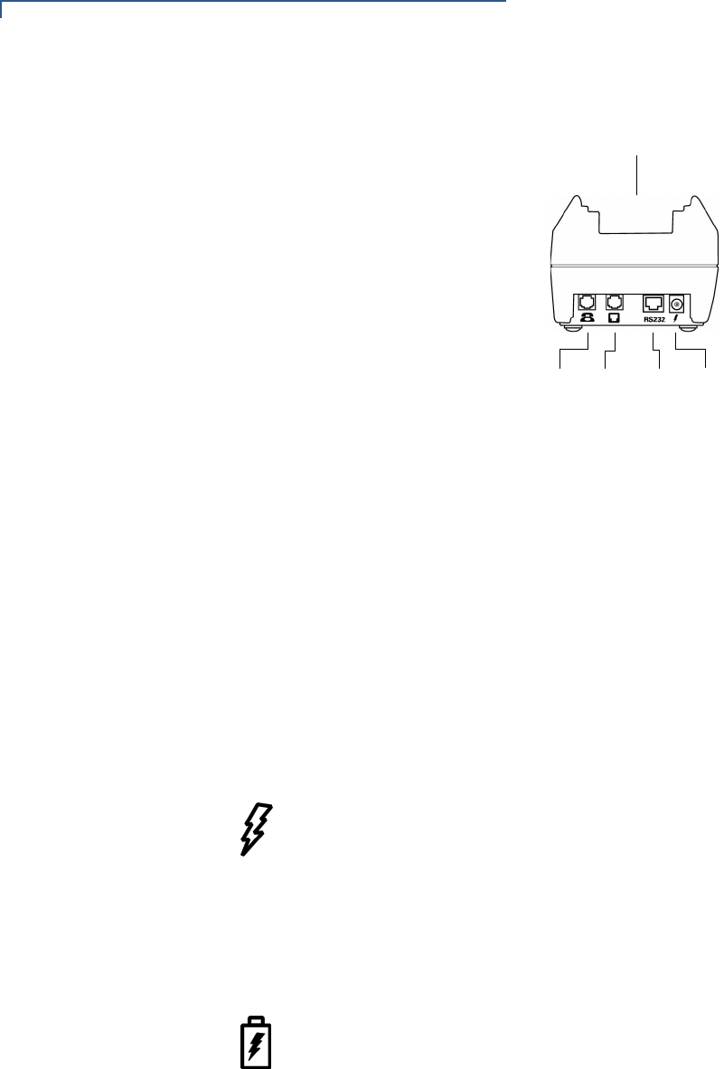
Figure 22 Omni 3600 Base Features: Back (Telco models)
The Omni 3600 base
•recharges the smart battery within a docked Omni 3600 terminal,
•charges a spare smart battery pack placed in the spare battery dock,
•establishes communications to a host through a 14.4 Kbps modem (Telco
port), and
•connects to optional peripherals through the serial (RS-232) port (see
Peripheral Devices).
The following are the physical features of the Omni 3600 base (Figure 21 and
Figure 22):
•Three status LEDs (light emitting diodes) viewed left-to-right
•Terminal power LED:
•Steady green indicates the battery in the terminal is fully charged or
the terminal is docked, but has no battery.
•Flashing amber indicates the battery in the terminal is receiving a test
charge and is in the precharge state–the Omni 3600 base circuitry is
determining the charge state of the battery in terminal.
•Steady amber indicates the battery in the terminal is recharging.
•Battery charge state LED:
•Steady green indicates the spare battery docked in the Omni 3600
base is fully charged or is no longer charging.
•Flashing amber indicates the spare battery is receiving a test charge
and is in the precharge state–the Omni 3600 base circuitry is
determining the charge state of the spare battery.
•Steady amber indicates the battery in the spare battery dock is
recharging.
POWER
PORT
RS-232
PORT
TELCO
PORT
TELSET
PORT
TERMINAL DOCKING
CRADLE
OMNI 3600 TERMINAL AND OMNI 3600 BASE INSTALLATION
Omni 3600 Base
OMNI 3600 REFERENCE MANUAL 25
•Omni 3600 base power LED:
•Steady green indicates the Omni 3600 base is connected to the power
adapter.
•Not lit indicates the Omni 3600 base is not connected to the power
pack, the power pack is not connected to the wall outlet, or the power
is out.
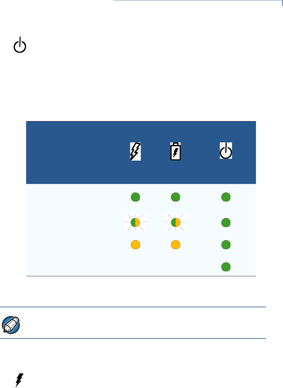
Table 1 illustrates different LED states.
•Docking cradle: For Omni 3600 terminal (Figure 21) smart battery recharging
and data transfers.
•Spare battery docking station and optional spare battery: The recessed area
in the top-rear of the Omni 3600 base is the dock to charge and store a smart
battery. The spare battery LED does not light if no spare battery is present.
•Power port: The round port on back of Omni 3600 base (icon at left) connects
the Omni 3600 base to the power pack.
•Communications ports: The ports on the back of the Omni 3600 base allow
telephone or LAN line connectivity and peripheral device support.
Table 1 Omni 3600 Base LED Status
Battery State
LED
Terminal
Power
Spare
Battery
Omni 3600 Base
Power
Fully charged battery in
Omni 3600 terminal and spare
battery in Omni 3600 base
Pre-charge state
Charging
Omni 3600 base has power
NOTE The Omni 3600 terminal will not automatically turn off or sleep when docked; it
must be turned off manually (see Turn On/Off the Omni 3600 Terminal).
OMNI 3600 TERMINAL AND OMNI 3600 BASE INSTALLATION
Omni 3600 Base
26 OMNI 3600 REFERENCE MANUAL
Power Connection The Omni 3600 base unit must be plugged in to a power outlet to
•recharge a smart battery in a docked terminal,
•charge spare smart batteries,
•communicate with peripheral devices, and
•establish Telco host connections.
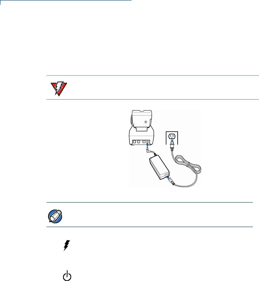
Figure 23 Power Pack Connection (Docked Terminal)
To connect the Omni 3600 base to power (Figure 23):
1Insert the round barrel connector into the power port (icon at left) on the far
right of the Omni 3600 base.
2Insert the power cable into the power pack.
3Plug the power cable into a wall outlet or surge protector. When the
Omni 3600 base is powered, the far-right LED (icon at left) lights steady
green.
WARNING
Do not plug the power pack into an outdoor outlet.
NOTE It is recommended that the power pack be plugged into a power surge protector to
protect against possible damage caused by lightning strikes and electrical surges.
OMNI 3600 TERMINAL AND OMNI 3600 BASE INSTALLATION
Omni 3600 Base
OMNI 3600 REFERENCE MANUAL 27
Omni 3600
Terminal Docking
Place the Omni 3600 terminal in the docking cradle (Figure 23) to recharge the
terminal smart battery, establish communications connections for data transfers,
and communicate with peripheral devices.
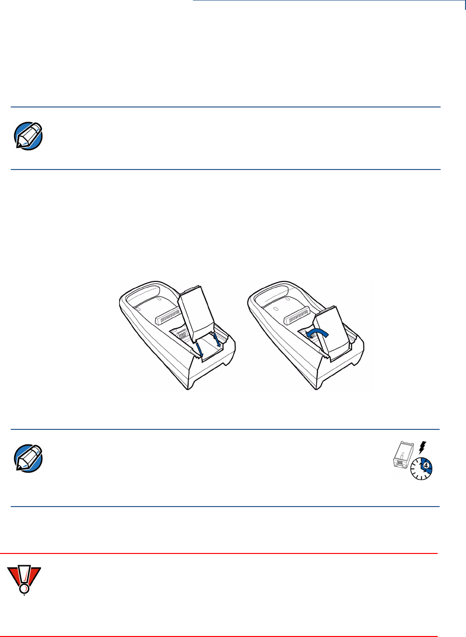
Spare Smart
Battery Pack
Spare smart battery packs for the Omni 3600 terminal can be ordered from
VeriFone. See Accessories and Documentation for ordering information. To
charge a smart battery in the Omni 3600 base, place the smart battery into the
Omni 3600 base spare smart battery dock as shown in Figure 24. The smart
battery dock is keyed so that the smart battery can only be inserted in one way.
Figure 24 Spare Smart Battery Docking
Keep a spare smart battery charging in the Omni 3600 base battery dock to
ensure that a fully charged battery is always available.
On initial use, allow the Omni 3600 smart battery to charge a maximum of 4 hours
and fully discharge during normal operation to ensure reliable battery operation.
See Smart Battery for charge/discharge procedures.
NOTE The Omni 3600 terminal will not turn off or enter sleep mode while docked on the
Omni 3600 base. This ensures that the unit is not placed into sleep mode during
data transfers. The unit must be turned off manually when docked on the
Omni 3600 base. See Turn On/Off the Omni 3600 Terminal.
NOTE Allow the spare battery to remain in the Omni 3600 base unit for a
minimum of 2 hours, maximum of 4 hours to ensure the battery
receives a full charge. Note that a new Li-ion battery’s full performance
is achieved only after two or three complete charge and discharge
cycles.
CAUTION Conserve battery power by turning the Omni 3600 terminal off when not in use. If
the terminal is not to be used for several days, remove the battery from the
terminal as it continues to discharge even when the terminal is turned off.
If the Omni 3600 base unit is not plugged in, remove the smart battery from the
dock to avoid the smart battery discharging in the Omni 3600 base unit.
OMNI 3600 TERMINAL AND OMNI 3600 BASE INSTALLATION
Omni 3600 Base
28 OMNI 3600 REFERENCE MANUAL
Omni 3600 Base
Communications
Ports
The communications ports are located on the back of the Omni 3600 base (see
Figure 25). When the Omni 3600 terminal is docked in the Omni 3600 base, a
communication port in the terminal is opened, and data can transfer from the
Omni 3600 terminal back and forth through the Omni 3600 base over the modem
connection to and from your service provider or merchant contact.
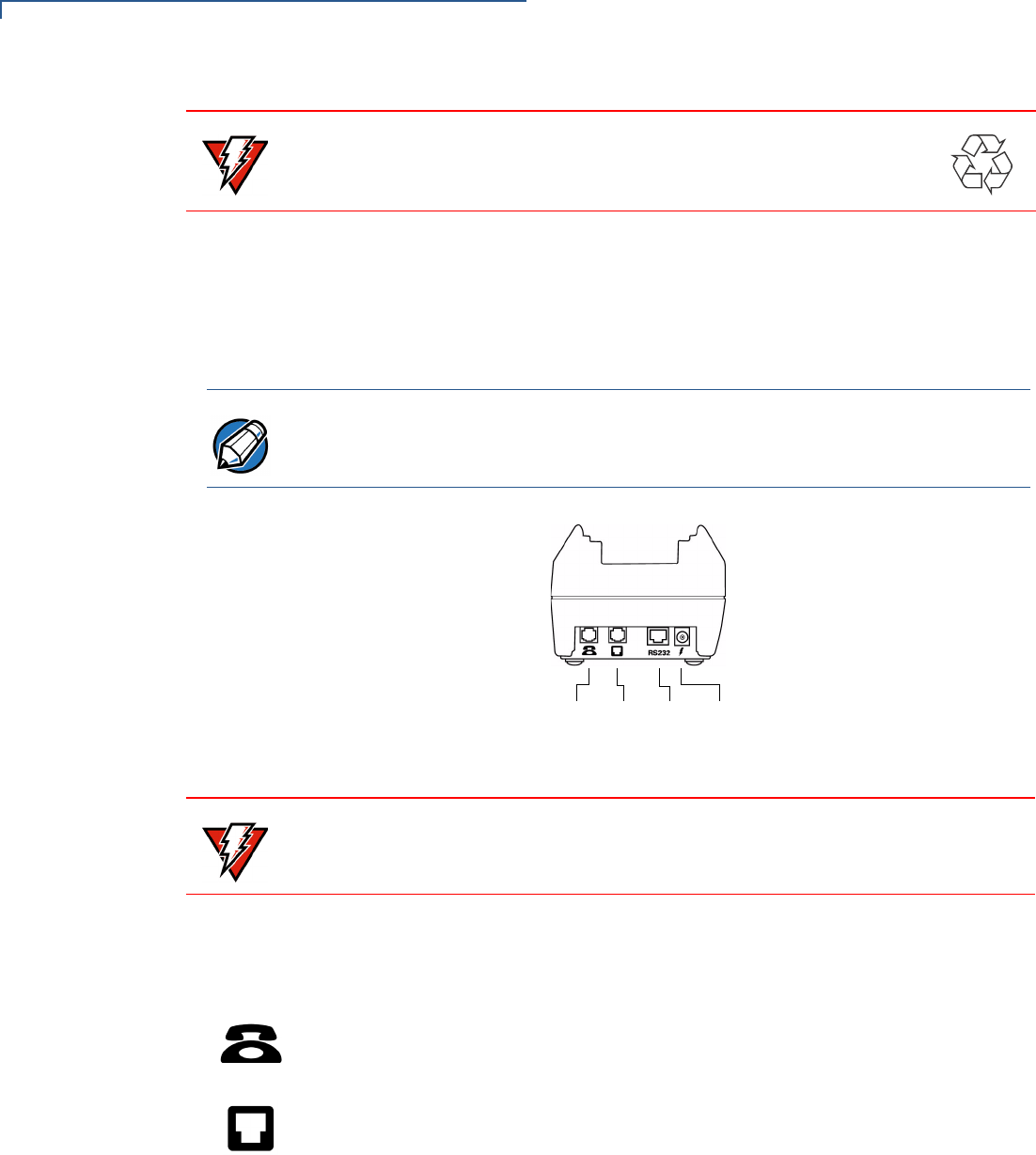
Figure 25 Omni 3600 Base Connection Ports
Telephone Line Ports
There are two RJ11-type modular phone jacks (Figure 25) to connect the
Omni 3600 base to a telephone line:
•The first port is identified by a telephone-shaped Telset icon shown at left. Use
this port to connect a telephone to the terminal (pass-through connection)
•The second port is identified by the Telco icon shown at left. Use this port to
directly connect the Omni 3600 series terminal to a telephone wall jack
Telephone Line Connections
To make a direct connection, connect a telephone cord from the Telco port on the
Omni 3600 base directly to a telephone wall jack (Figure 26). Do not string the
telephone cord across a walkway or place it so as to interfere in high-traffic areas.
With a direct connection, the phone line is dedicated to the terminal.
WARNING Do not dispose of batteries in a fire. Li-ion batteries must be recycled
or disposed of properly. Do not dispose of Li-ion batteries in municipal
waste sites.
NOTE The Omni 3600 base must be plugged into power to establish communications
connections.
POWER PORTRS-232
PORT
TELCO
PORT
TELSET
PORT
WARNING Do not remove the Omni 3600 terminal from the Omni 3600 base during data
transfers. This terminates the connection and data loss may result.
OMNI 3600 TERMINAL AND OMNI 3600 BASE INSTALLATION
Omni 3600 Base
OMNI 3600 REFERENCE MANUAL 29
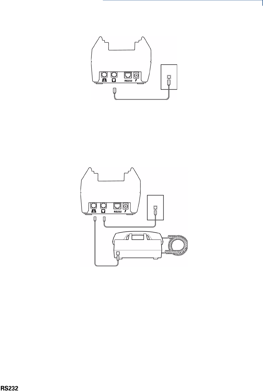
Figure 26 Direct Connection
Pass-through connection — Run a telephone cord from the Telco port on the
Omni 3600 base to the RJ11 jack on a standard telephone (Figure 27). Do not
string the telephone cord across a walkway or place it so as to interfere in high-
traffic areas. With a pass-through connection, the phone line is busy during
downloads.
Figure 27 Pass-through Connection
Peripheral Devices
The Omni 3600 base supports a line of VeriFone peripheral devices designed to
use with point-of-sale terminals. Use the RS-232 port on the back panel of the
Omni 3600 base to connect these optional devices.
The following sections discuss the optional devices supported by the Omni 3600.
Other optional devices may be supported. For more information, please contact
your VeriFone distributor.
Optional Peripheral Device Port
Right of the RJ11 ports is a RJ45-type modular jack (serial port), labeled RS232:
•The RS232 serial port (icon shown at left) connects a VeriFone CR 600 check
reader or other peripheral device to the Omni 3600 base
The Omni 3600 base does not support external PIN pad devices.
OMNI 3600 TERMINAL AND OMNI 3600 BASE INSTALLATION
Omni 3600 Base
30 OMNI 3600 REFERENCE MANUAL
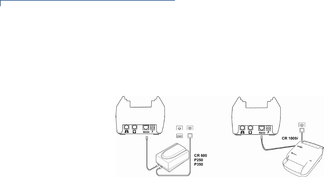
Check Readers Supported
The Omni 3600 base supports two VeriFone check readers: CR 600 and
CR 1000i. Contact your VeriFone representative or visit the online store at
www.verifone.com for information on these devices. Figure 28 provides an
example of a peripheral connection.
Figure 28 Example Peripheral Connections
External Printers Supported
Although the Omni 3600 has an internal thermal printer (see Paper Installation), it
may be convenient to print larger print runs (for example, daily or weekly reports)
to an external printer. The Omni 3600 base supports three VeriFone external
printers: P250, P350, and P900. Contact your VeriFone representative or visit the
online store at www.verifone.com for information on these devices. External
printer connections are through the same port as check readers (see Figure 28).