Verifone V240MPLUS Point of Sales Terminal User Manual
VeriFone Inc Point of Sales Terminal
UserManual.wiki
>
Verifone
>
V240MPLUS User Manual
>
User Manual
Contents
1.
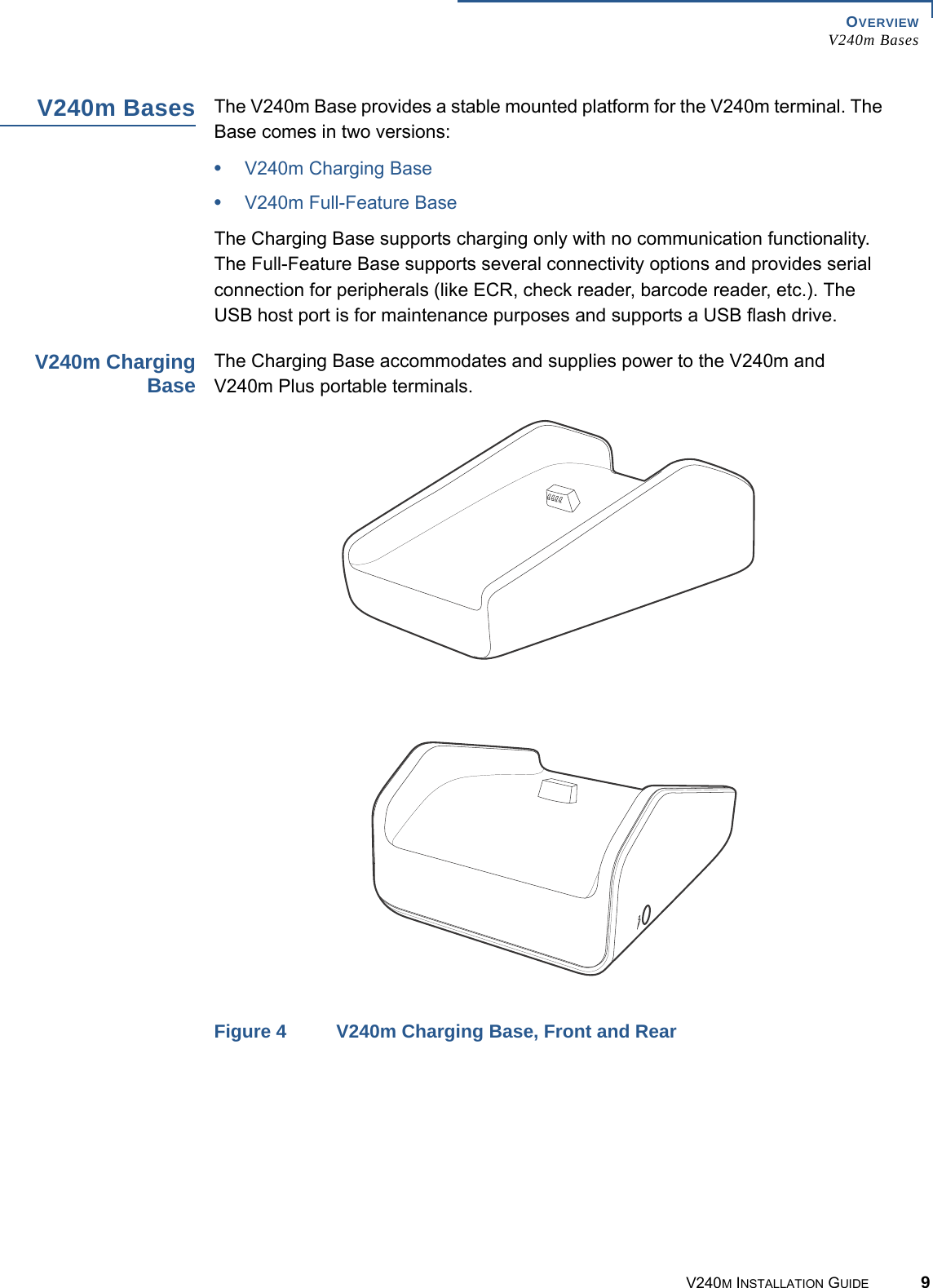
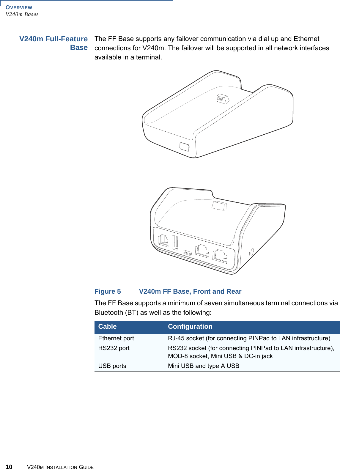
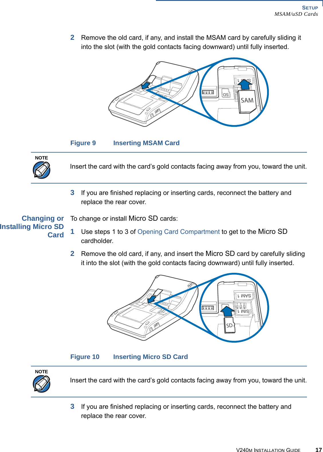
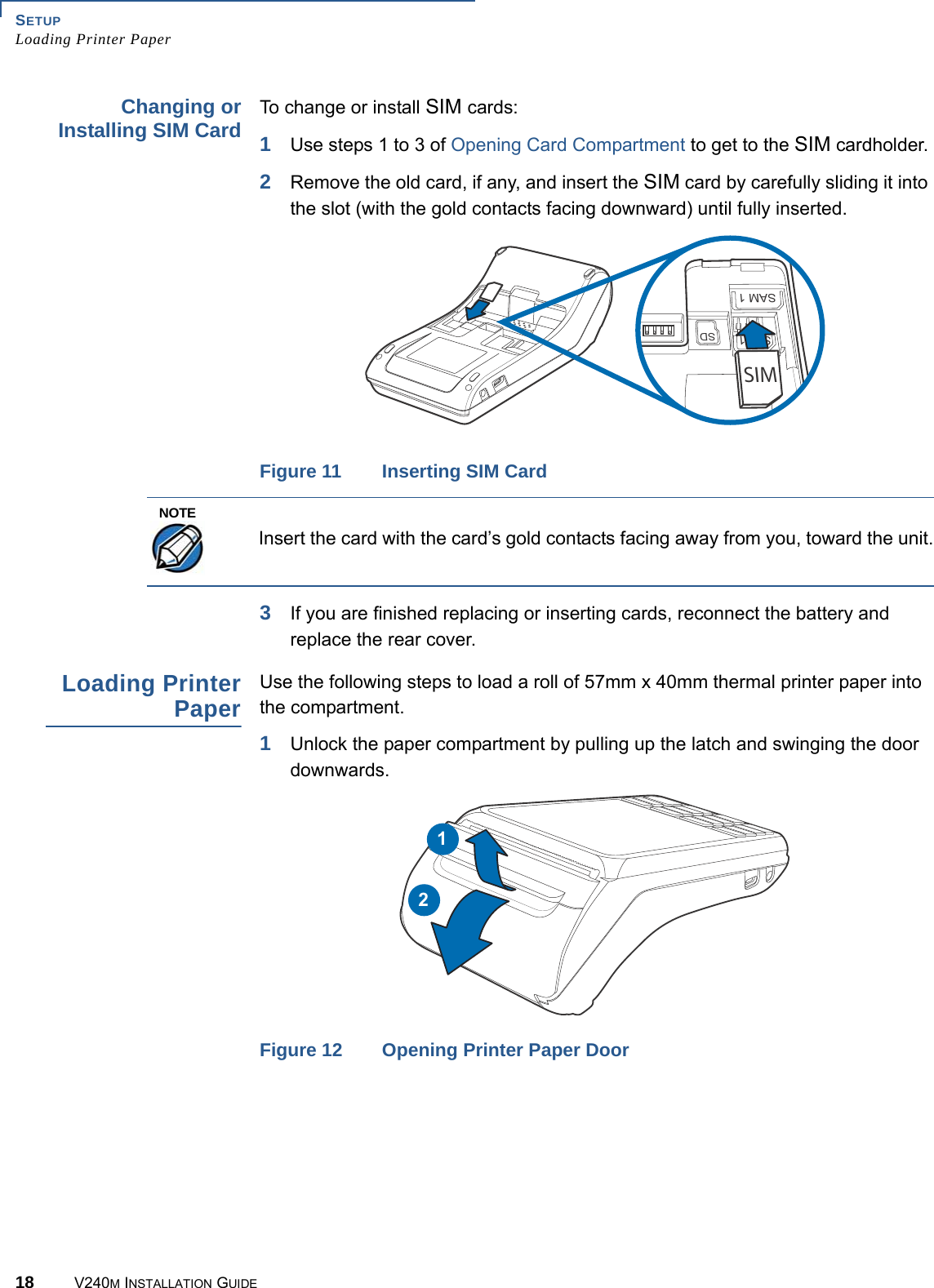
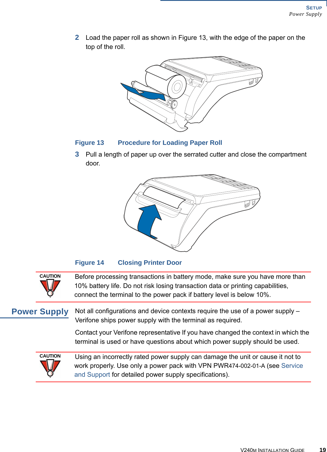
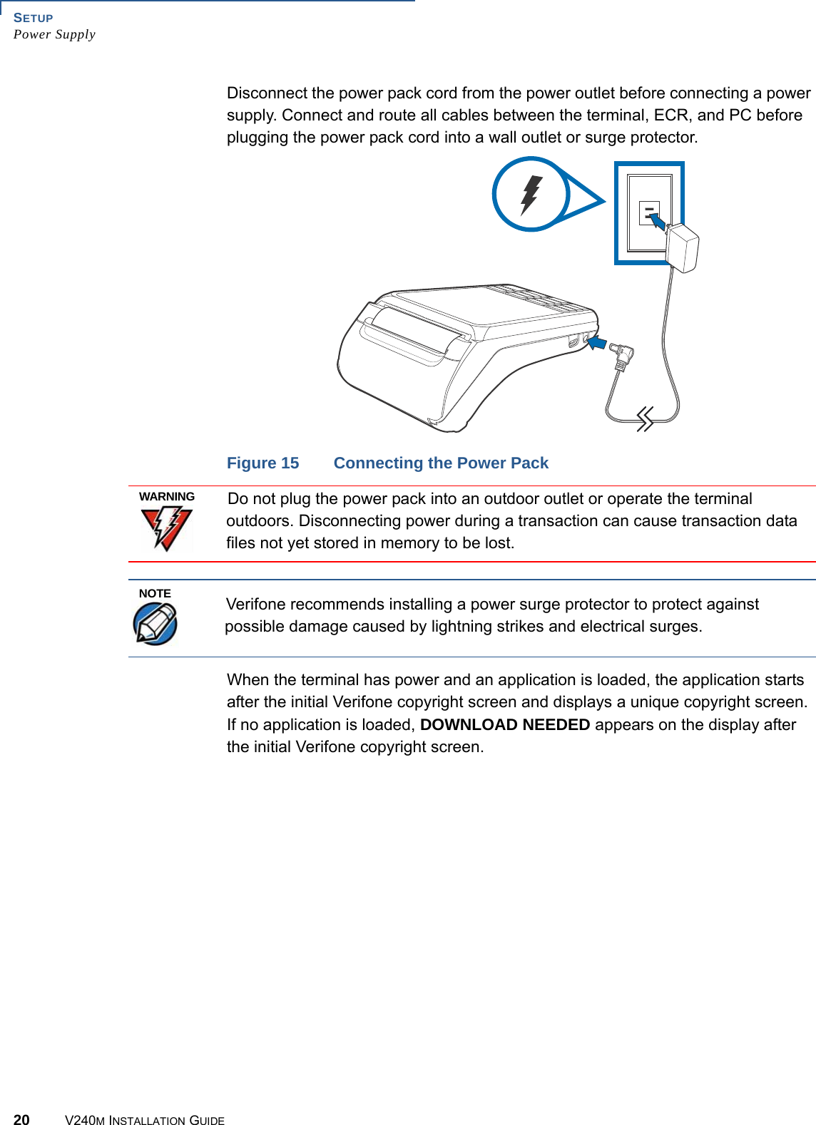
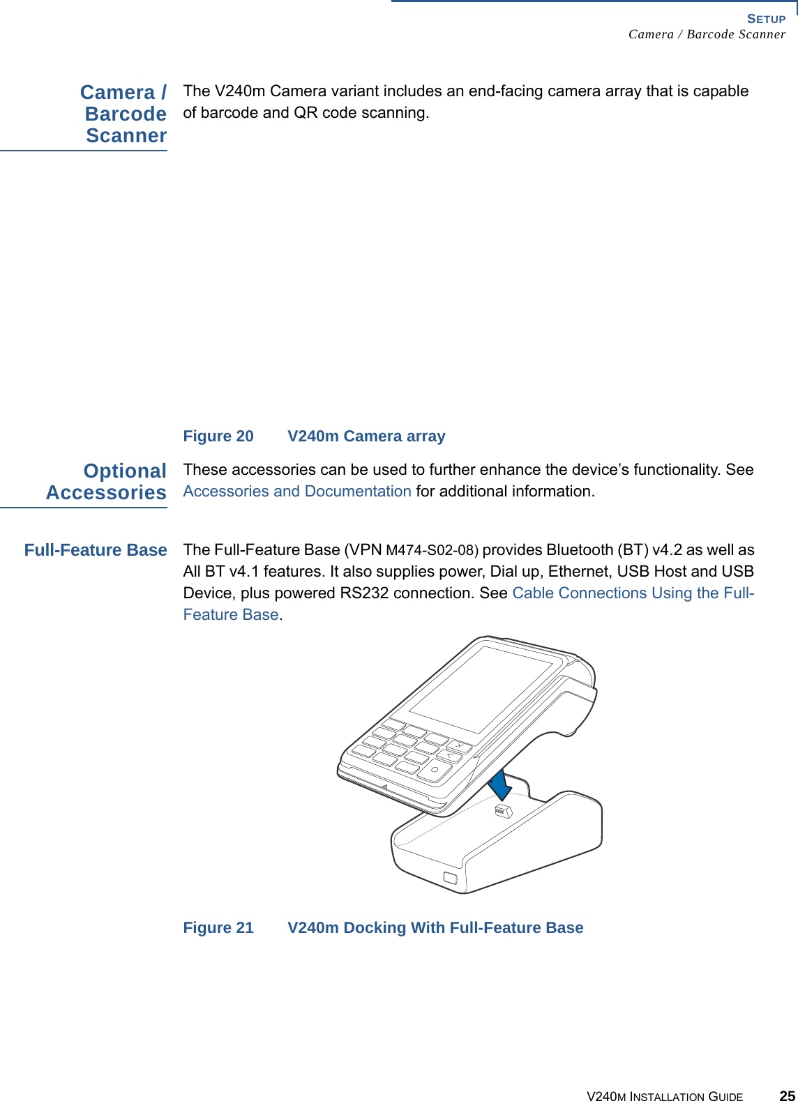
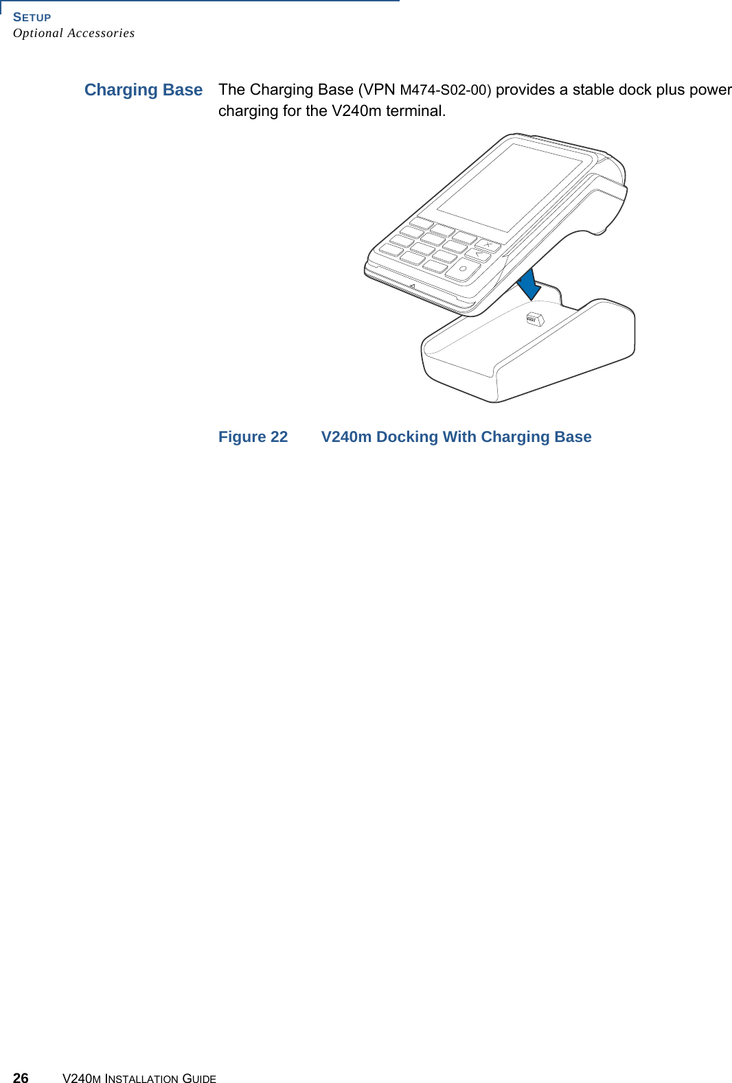
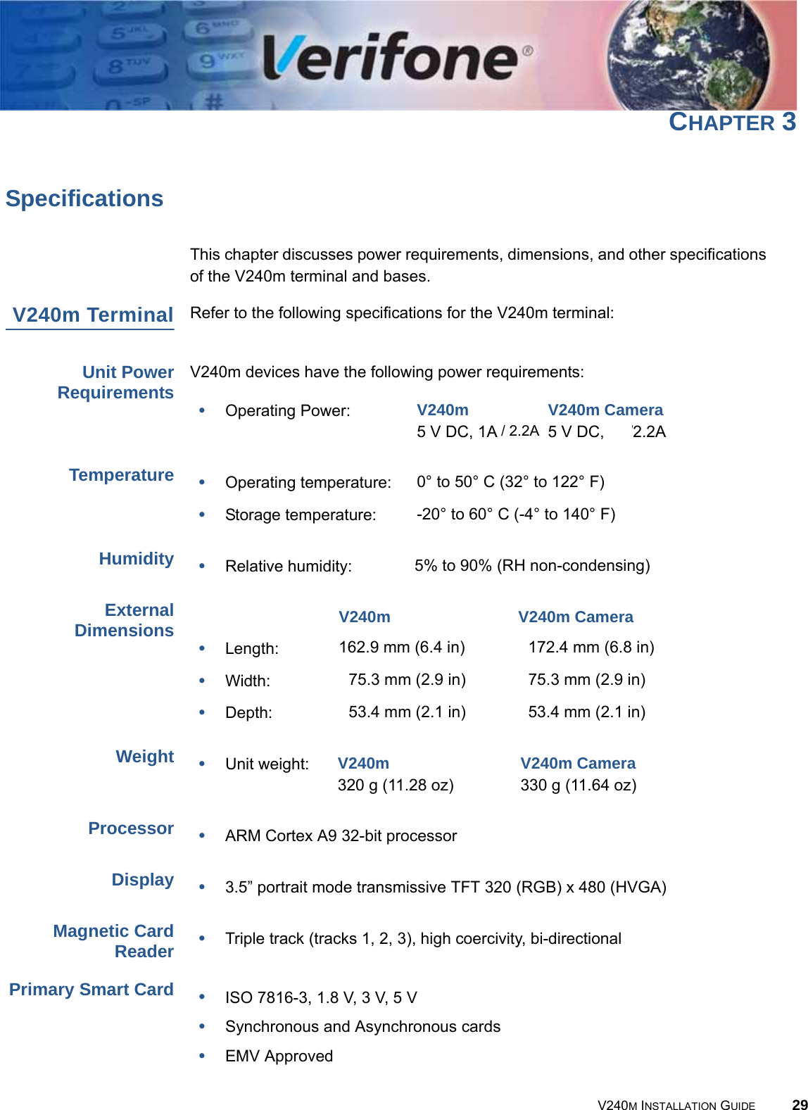
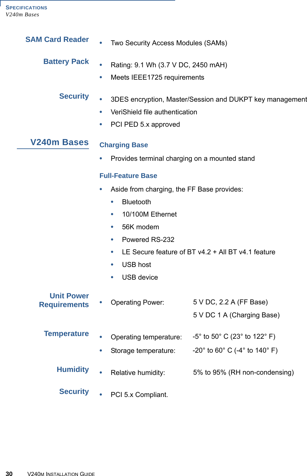
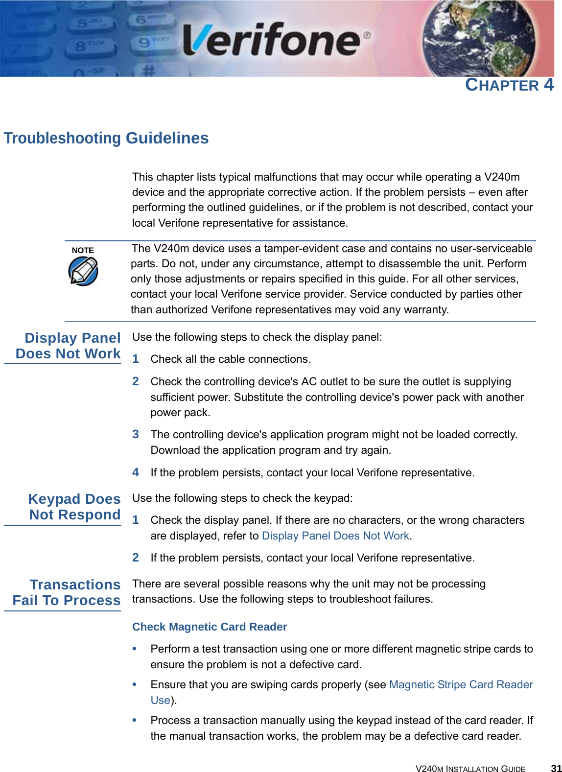
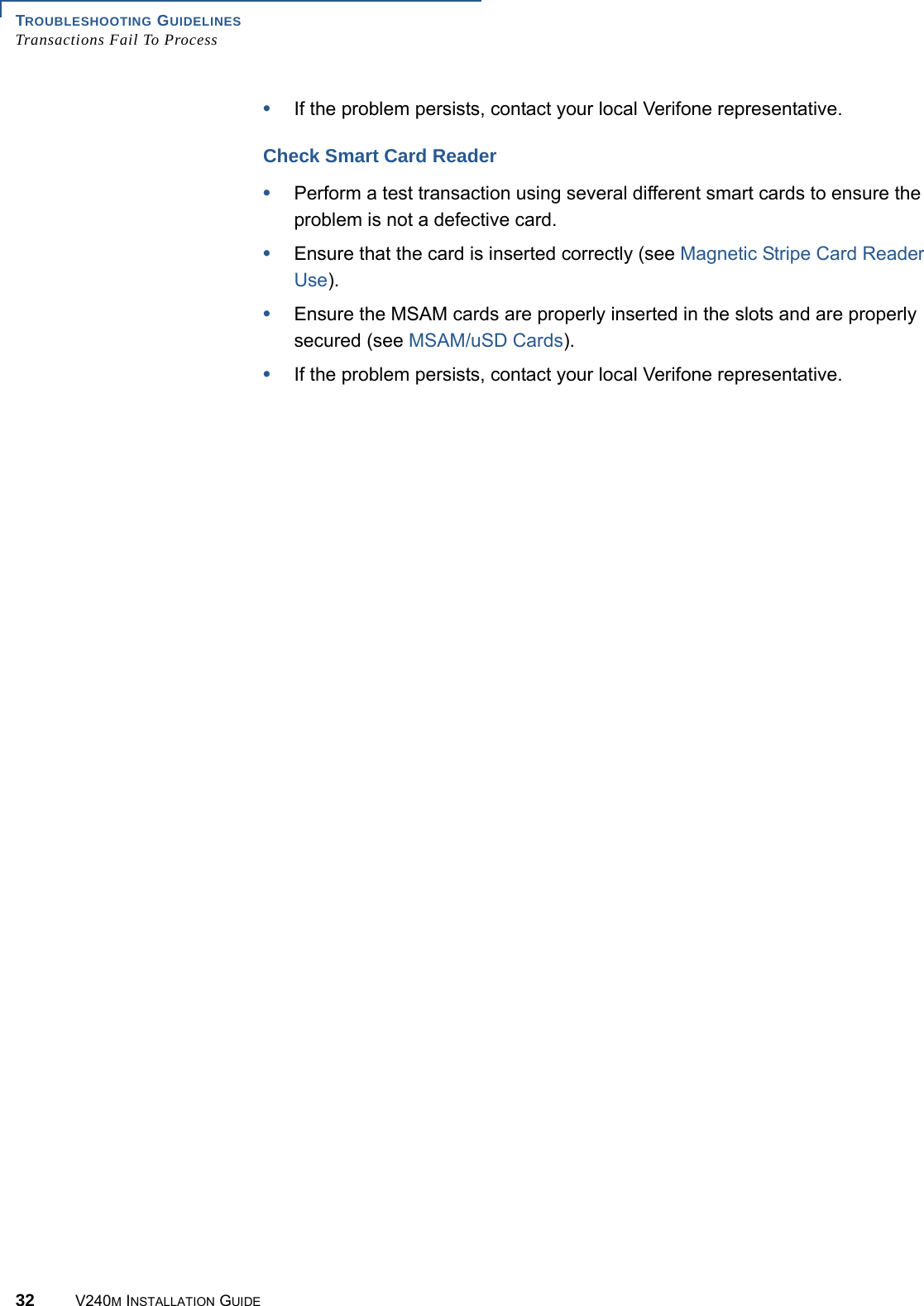
DOC474_003_EN_A_V240m_Installation_Guide_RevA2
2.
User Manual
User Manual
Navigation menu
Upload a User Manual
Namespaces
Wiki Guide
HTML
PDF
Info
Views
User Manual
Discussion / Help
Navigation