Verifone V240MPLUS Point of Sales Terminal User Manual
VeriFone Inc Point of Sales Terminal
Verifone >
Contents
- 1. DOC474_003_EN_A_V240m_Installation_Guide_RevA2
- 2. User Manual
User Manual

Verifone Part Number DOC474-003-EN-B, Revision 001
V240m
Installation Guide

All rights reserved. No part of the contents of this document may be reproduced or transmitted in any form without the written
permission of Verifone, Inc.
The information contained in this document is subject to change without notice. Although Verifone has attempted to ensure the
accuracy of the contents of this document, this document may include errors or omissions. The examples and sample programs are
for illustration only and may not be suited for your purpose. You should verify the applicability of any example or sample program
before placing the software into productive use. This document, including without limitation the examples and software programs, is
supplied “As-Is.”
Verifone Inc.
1-800-Verifone
www.verifone.com
Verifone Part Number DOC474-003-EN-B, Revision 001
V240m Installation Guide
© 2018 Verifone, Inc.
Verifone and the Verifone logo, are registered trademarks of Verifone. Other brand names or trademarks associated with Verifone’s
products and services are trademarks of Verifone, Inc.
All other brand names and trademarks appearing in this manual are the property of their respective holders.
Product Warranty
For product warranty information, go to http://www.verifone.com/terms.
Comments? Please e-mail all comments on this document to your local Verifone Support Team.

V240M INSTALLATION GUIDE 3
CONTENTS
PREFACE . . . . . . . . . . . . . . . . . . . . . . . . . . . . . . . . . . . . . . . 5
Audience. . . . . . . . . . . . . . . . . . . . . . . . . . . . . . . . . . . . . . . . . . . . . . . . . . . . . . . . 5
Organization . . . . . . . . . . . . . . . . . . . . . . . . . . . . . . . . . . . . . . . . . . . . . . . . . . . . . 5
Related Documentation . . . . . . . . . . . . . . . . . . . . . . . . . . . . . . . . . . . . . . . . . . . . 5
Guide Conventions. . . . . . . . . . . . . . . . . . . . . . . . . . . . . . . . . . . . . . . . . . . . . . . . 5
Acronym Definitions . . . . . . . . . . . . . . . . . . . . . . . . . . . . . . . . . . . . . . . . . . . . 6
CHAPTER 1
Overview V240m Terminal. . . . . . . . . . . . . . . . . . . . . . . . . . . . . . . . . . . . . . . . . . . . . . . . . . 7
Front Functions. . . . . . . . . . . . . . . . . . . . . . . . . . . . . . . . . . . . . . . . . . . . . . . . 7
Back Functions . . . . . . . . . . . . . . . . . . . . . . . . . . . . . . . . . . . . . . . . . . . . . . . . 8
End Functions. . . . . . . . . . . . . . . . . . . . . . . . . . . . . . . . . . . . . . . . . . . . . . . . . 8
V240m Bases . . . . . . . . . . . . . . . . . . . . . . . . . . . . . . . . . . . . . . . . . . . . . . . . . . . . 9
V240m Charging Base . . . . . . . . . . . . . . . . . . . . . . . . . . . . . . . . . . . . . . . . . . 9
V240m Full-Feature Base. . . . . . . . . . . . . . . . . . . . . . . . . . . . . . . . . . . . . . . 10
Features and Benefits . . . . . . . . . . . . . . . . . . . . . . . . . . . . . . . . . . . . . . . . . . . . 11
Exceptional Ease of Use and Ergonomics . . . . . . . . . . . . . . . . . . . . . . . . . . 11
Critical Security Protection . . . . . . . . . . . . . . . . . . . . . . . . . . . . . . . . . . . . . . 11
CHAPTER 2
Setup Selecting Location . . . . . . . . . . . . . . . . . . . . . . . . . . . . . . . . . . . . . . . . . . . . . . . 13
Environmental Factors . . . . . . . . . . . . . . . . . . . . . . . . . . . . . . . . . . . . . . . . . 14
Electrical Considerations . . . . . . . . . . . . . . . . . . . . . . . . . . . . . . . . . . . . . . . 14
Contactless Considerations . . . . . . . . . . . . . . . . . . . . . . . . . . . . . . . . . . . . . 14
PIN Protection Measures . . . . . . . . . . . . . . . . . . . . . . . . . . . . . . . . . . . . . . . . . . 14
Unpacking Shipping Carton . . . . . . . . . . . . . . . . . . . . . . . . . . . . . . . . . . . . . . . . 15
MSAM/uSD Cards . . . . . . . . . . . . . . . . . . . . . . . . . . . . . . . . . . . . . . . . . . . . . . . 15
Opening Card Compartment. . . . . . . . . . . . . . . . . . . . . . . . . . . . . . . . . . . . . 15
Changing or Installing MSAMs . . . . . . . . . . . . . . . . . . . . . . . . . . . . . . . . . . . 16
Changing or Installing Micro SD Card. . . . . . . . . . . . . . . . . . . . . . . . . . . . . . 17
Changing or Installing SIM Card. . . . . . . . . . . . . . . . . . . . . . . . . . . . . . . . . . 18
Loading Printer Paper. . . . . . . . . . . . . . . . . . . . . . . . . . . . . . . . . . . . . . . . . . . . . 18
Power Supply . . . . . . . . . . . . . . . . . . . . . . . . . . . . . . . . . . . . . . . . . . . . . . . . . . . 19
USB Power Supply . . . . . . . . . . . . . . . . . . . . . . . . . . . . . . . . . . . . . . . . . . . . 21
Cable Connections . . . . . . . . . . . . . . . . . . . . . . . . . . . . . . . . . . . . . . . . . . . . . . . 21
Cable Connections Using the Full-Feature Base . . . . . . . . . . . . . . . . . . . . . 22
Smart Card Reader . . . . . . . . . . . . . . . . . . . . . . . . . . . . . . . . . . . . . . . . . . . . . . 23
Magnetic Stripe Card Reader Use . . . . . . . . . . . . . . . . . . . . . . . . . . . . . . . . . . . 24
Contactless Transactions . . . . . . . . . . . . . . . . . . . . . . . . . . . . . . . . . . . . . . . . . . 24
Camera / Barcode Scanner . . . . . . . . . . . . . . . . . . . . . . . . . . . . . . . . . . . . . . . . 25
Optional Accessories . . . . . . . . . . . . . . . . . . . . . . . . . . . . . . . . . . . . . . . . . . . . . 25
Full-Feature Base . . . . . . . . . . . . . . . . . . . . . . . . . . . . . . . . . . . . . . . . . . . . . 25
Charging Base . . . . . . . . . . . . . . . . . . . . . . . . . . . . . . . . . . . . . . . . . . . . . . . 26
Periodic Inspection . . . . . . . . . . . . . . . . . . . . . . . . . . . . . . . . . . . . . . . . . . . . . . . 27

4V240M INSTALLATION GUIDE
CHAPTER 3
Specifications V240m Terminal . . . . . . . . . . . . . . . . . . . . . . . . . . . . . . . . . . . . . . . . . . . . . . . . . 29
Unit Power Requirements. . . . . . . . . . . . . . . . . . . . . . . . . . . . . . . . . . . . . . . 29
Temperature . . . . . . . . . . . . . . . . . . . . . . . . . . . . . . . . . . . . . . . . . . . . . . . . . 29
Humidity . . . . . . . . . . . . . . . . . . . . . . . . . . . . . . . . . . . . . . . . . . . . . . . . . . . . 29
External Dimensions. . . . . . . . . . . . . . . . . . . . . . . . . . . . . . . . . . . . . . . . . . . 29
Weight. . . . . . . . . . . . . . . . . . . . . . . . . . . . . . . . . . . . . . . . . . . . . . . . . . . . . . 29
Processor . . . . . . . . . . . . . . . . . . . . . . . . . . . . . . . . . . . . . . . . . . . . . . . . . . . 29
Display . . . . . . . . . . . . . . . . . . . . . . . . . . . . . . . . . . . . . . . . . . . . . . . . . . . . . 29
Magnetic Card Reader . . . . . . . . . . . . . . . . . . . . . . . . . . . . . . . . . . . . . . . . . 29
Primary Smart Card . . . . . . . . . . . . . . . . . . . . . . . . . . . . . . . . . . . . . . . . . . . 29
SAM Card Reader. . . . . . . . . . . . . . . . . . . . . . . . . . . . . . . . . . . . . . . . . . . . . 30
Battery Pack . . . . . . . . . . . . . . . . . . . . . . . . . . . . . . . . . . . . . . . . . . . . . . . . . 30
Security. . . . . . . . . . . . . . . . . . . . . . . . . . . . . . . . . . . . . . . . . . . . . . . . . . . . . 30
V240m Bases . . . . . . . . . . . . . . . . . . . . . . . . . . . . . . . . . . . . . . . . . . . . . . . . . . . 30
Unit Power Requirements. . . . . . . . . . . . . . . . . . . . . . . . . . . . . . . . . . . . . . . 30
Temperature . . . . . . . . . . . . . . . . . . . . . . . . . . . . . . . . . . . . . . . . . . . . . . . . . 30
Humidity . . . . . . . . . . . . . . . . . . . . . . . . . . . . . . . . . . . . . . . . . . . . . . . . . . . . 30
Security. . . . . . . . . . . . . . . . . . . . . . . . . . . . . . . . . . . . . . . . . . . . . . . . . . . . . 30
CHAPTER 4
Troubleshooting
Guidelines Display Panel Does Not Work . . . . . . . . . . . . . . . . . . . . . . . . . . . . . . . . . . . . . . 31
Keypad Does Not Respond . . . . . . . . . . . . . . . . . . . . . . . . . . . . . . . . . . . . . . . . 31
Transactions Fail To Process. . . . . . . . . . . . . . . . . . . . . . . . . . . . . . . . . . . . . . . 31
CHAPTER 5
Service and Support Maintenance and Cleaning. . . . . . . . . . . . . . . . . . . . . . . . . . . . . . . . . . . . . . . . . 33
Service Returns . . . . . . . . . . . . . . . . . . . . . . . . . . . . . . . . . . . . . . . . . . . . . . . . . 33
Accessories and Documentation . . . . . . . . . . . . . . . . . . . . . . . . . . . . . . . . . . . . 35
Cables. . . . . . . . . . . . . . . . . . . . . . . . . . . . . . . . . . . . . . . . . . . . . . . . . . . . . . 35
Power Supply . . . . . . . . . . . . . . . . . . . . . . . . . . . . . . . . . . . . . . . . . . . . . . . . 35
Accessories. . . . . . . . . . . . . . . . . . . . . . . . . . . . . . . . . . . . . . . . . . . . . . . . . . 35
Documentation . . . . . . . . . . . . . . . . . . . . . . . . . . . . . . . . . . . . . . . . . . . . . . . 35
APPENDIX A Caution and Warning Messages . . . . . . . . . . . . . . . . . . . . . . . . . . . . . . . . . . . . 37

V240M INSTALLATION GUIDE 5
PREFACE
This guide is the primary source of information for setting up and installing V240m
device.
Verifone ships variants of the V240m terminal for different markets. Your terminal
may have a different configuration, a different amount of memory, a different radio,
and may or may not have a camera.
Audience This guide provides simple descriptions of the V240m features and the basic
information for installing and configuring the V240m.
Organization This guide is organized as follows:
Chapter 1, Overview. Provides an overview of a V240m device.
Chapter 2, Setup. Explains how to set up and install the V240m and establish
connections with other devices.
Chapter 3, Specifications. Discusses the power requirements and dimensions of
V240m.
Chapter 4, Troubleshooting Guidelines. Provides troubleshooting tips.
Chapter 5, Service and Support. Provides information on contacting your Verifone
service provider, ordering accessories or documentation from Verifone, and
maintaining the V240m unit.
Appendix A, Caution and Warning Messages. Shows the UL/cUL certification-
compliant translations of all Warning and Caution messages in this installation
guide.
Related
Documentation To learn more about the V240m device, please refer to the following documents
and their associated Verifone Part Numbers (VPN):
V240m Certifications and Regulations VPN DOC474-001-EN
V240m Quick Installation Guide VPN DOC474-002-EN
Guide
Conventions
Please refer to the following document conventions for quickly identifying special
formatting.
Table 1 describes these conventions and provides examples of their use.
NOTE
Table 1 Document Conventions
Convention Meaning Example
Blue Text in blue indicates terms that
are cross-references. See Guide Conventions.
Italics Italic typeface indicates book
titles or emphasis. You must not use this unit
underwater.
NOTE
PREFACE
Guide Conventions
6V240M INSTALLATION GUIDE
Acronym Definitions
Please refer to Table 2 for the acronyms used in this manual.
Table 2 Acronym Definitions
Acronym Definitions
3DES Triple Data Encryption Algorithm
AC Alternating Current
ANSI American National Standards Institute
cUL Underwriters' Laboratories of Canada
DC Direct Current
DUKPT Derived Unique Key Per Transaction Method as defined in the
VISA’s POS Equipment Requirement: PIN processing and Data
Authentication, International Version 1.0, August 1988
ECR Electronic Cash Register
EMV Europay, MasterCard, and Visa
ISO International Organization for Standardization
MRA Merchandise Return Authorization
MSAM Multiple Secure Access Module
LAN Local Area Network
LCD Liquid Crystal Display
LED Light-Emitting Diode
PED PIN Entry Device
PIN Personal Identification Number
POS Point-of-Sale
RS-232 Recommend Standard number 232
SAM Secure Access Module
UL Underwriters Laboratories
USB Universal Serial Bus
VPN Verifone Part Number
The pencil icon is used to
highlight important information. RS-232-type devices do not work
on the communication port.
CAUTION
The caution symbol indicates
hardware or software failure, or
loss of data.
The unit is not waterproof or
dustproof, and is intended for
indoor use only.
WARNING
The lightning symbol is used as a
warning when bodily injury might
occur.
Due to risk of shock do not use
the unit near water.
Table 1 Document Conventions
Convention Meaning Example
V240M INSTALLATION GUIDE 7
CHAPTER 1
Overview
This chapter presents the basics on the V240m terminal and base.
V240m Terminal The V240m is a consumer-facing handheld device. The product’s design is
equally appealing as a handheld PINpad and robust enough to look and function
appropriately in a fixed mount setting.
The V240m can utilize over-the-air connectivity, facilitating mobile telephony
technology for sending and receiving data, using existing operator-provided 2G,
Wi-Fi, Bluetooth, or 3G connectivity.
This guide provides an introduction and basic setup procedures for V240m
terminals.
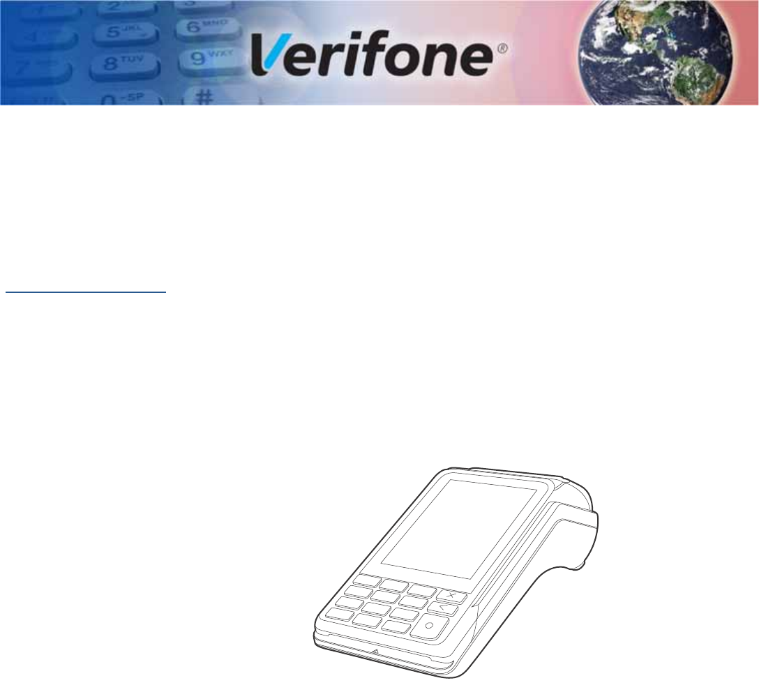
Figure 1 V240m Front View
Front Functions The V240m includes the following features:
•Capacitive touch LCD display and CTLS tap area
•Smart card reader
•Magnetic card reader
•Integrated thermal printer
•Secure keypad supporting 3x5 matrix containing 0-9, *, #, Cancel, Backspace/
Clear, and Enter keys.
•Dual-function Backspace/Clear key.
•Customer-entry for Cancel and Enter keys.
OVERVIEW
V240m Terminal
8V240M INSTALLATION GUIDE
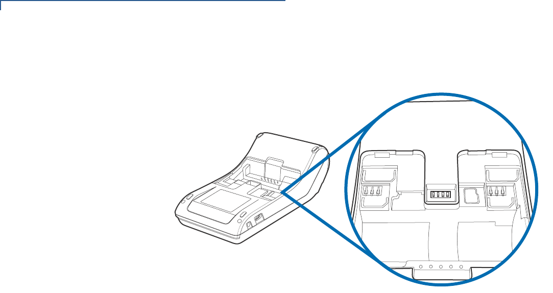
Back Functions After removing the rear cover and battery, the underside of the V240m device
shows the following:
SIM 1
SAM 1
SAM 2
SIM 2
SD
Figure 2 V240m Underside Compartment View
•A Micro SD slot
•Dual MSAM slots to support stored-value card programs or other merchant
card requirements
•Dual SIM Card compartments
End Functions The V240m Camera variant includes an end-facing camera array that is capable
of barcode and QR code scanning.:
Figure 3 V240m Camera array
OVERVIEW
V240m Bases
V240M INSTALLATION GUIDE 9
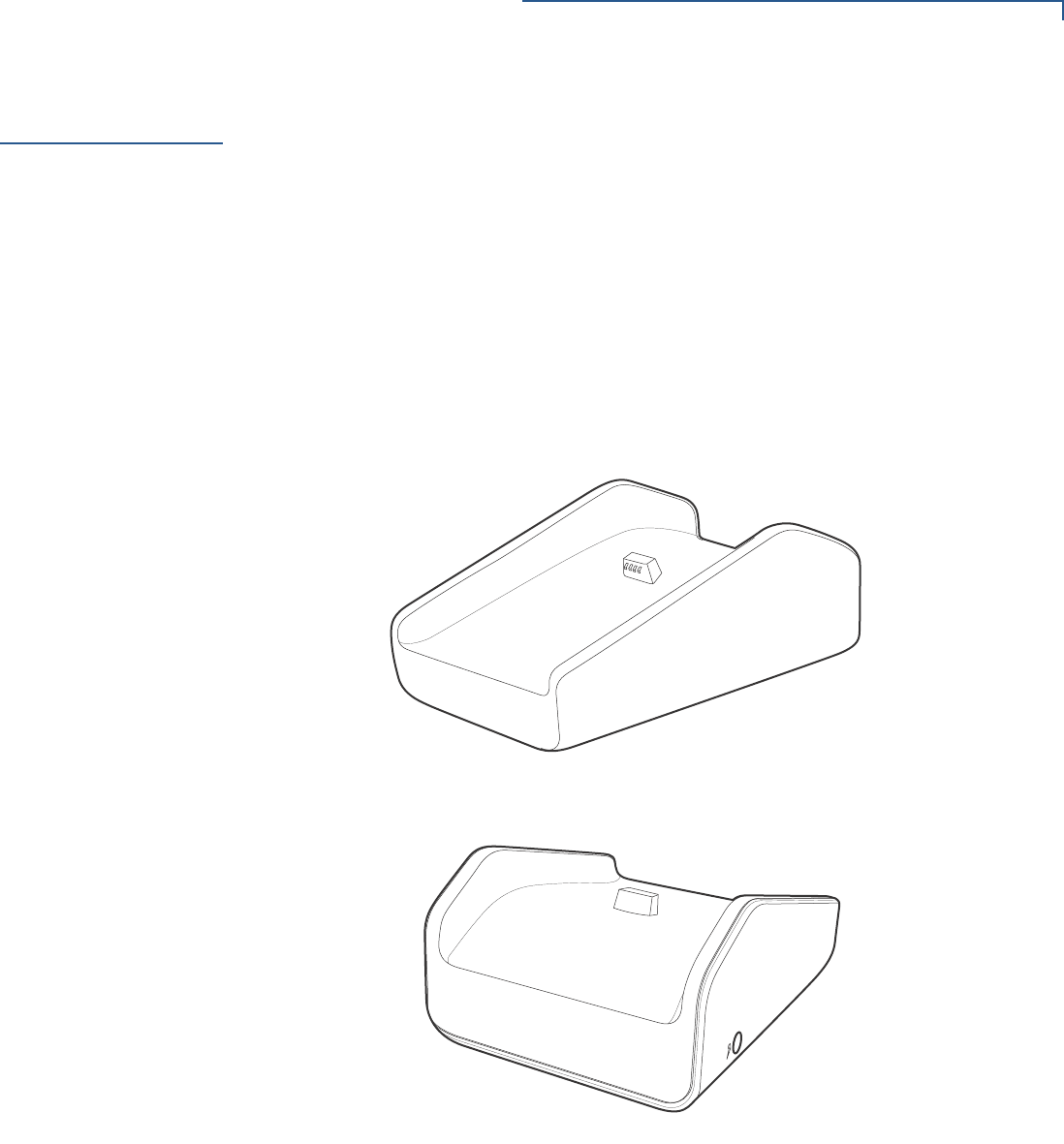
V240m Bases The V240m Base provides a stable mounted platform for the V240m terminal. The
Base comes in two versions:
•V240m Charging Base
•V240m Full-Feature Base
The Charging Base supports charging only with no communication functionality.
The Full-Feature Base supports several connectivity options and provides serial
connection for peripherals (like ECR, check reader, barcode reader, etc.). The
USB host port is for maintenance purposes and supports a USB flash drive.
V240m Charging
Base The Charging Base accommodates and supplies power to the V240m and
V240m Plus portable terminals.
Figure 4 V240m Charging Base, Front and Rear
OVERVIEW
V240m Bases
10 V240M INSTALLATION GUIDE
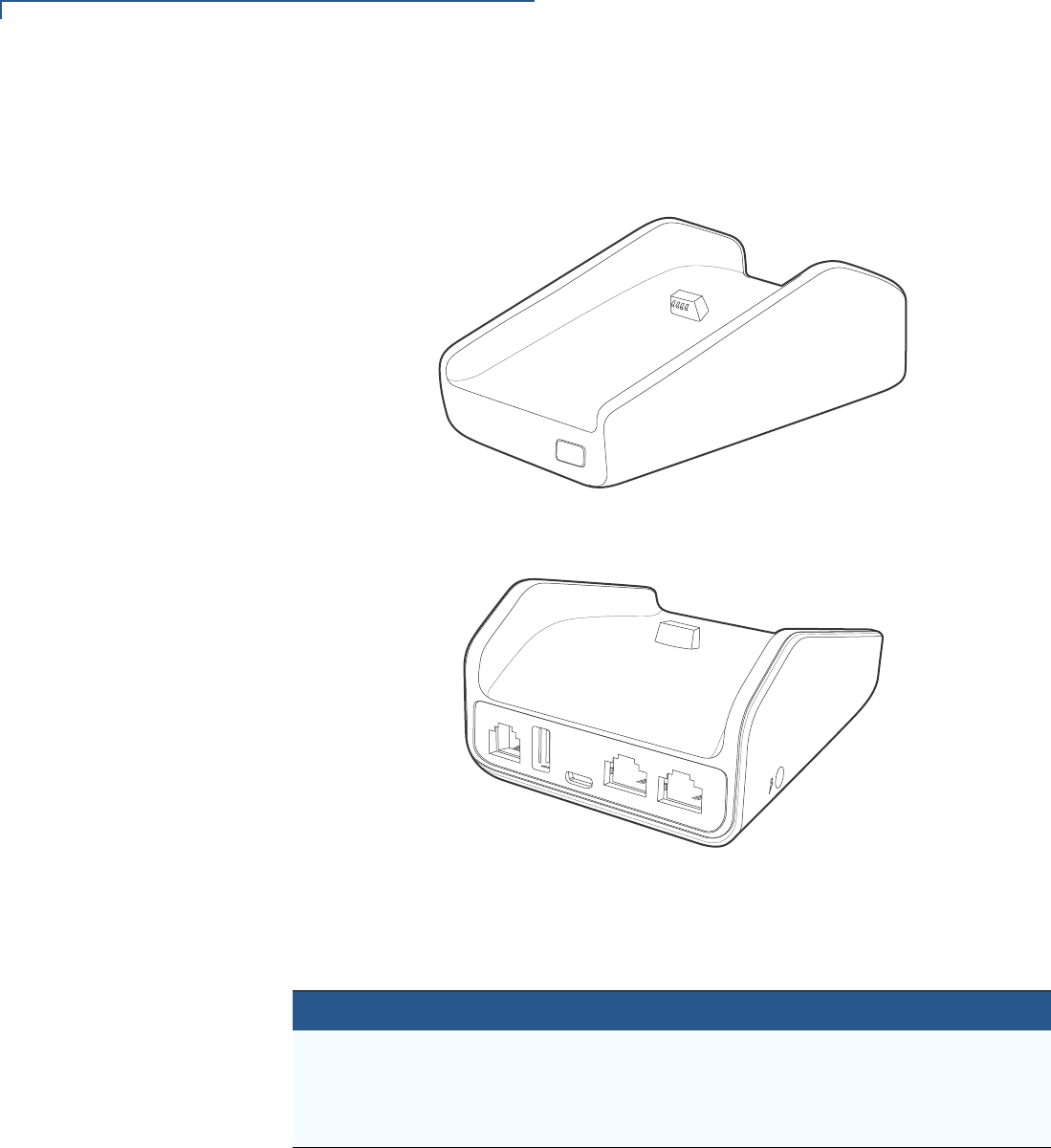
V240m Full-Feature
Base The FF Base supports any failover communication via dial up and Ethernet
connections for V240m. The failover will be supported in all network interfaces
available in a terminal.
Figure 5 V240m FF Base, Front and Rear
The FF Base supports a minimum of seven simultaneous terminal connections via
Bluetooth (BT) as well as the following:
Cable Configuration
Ethernet port RJ-45 socket (for connecting PINPad to LAN infrastructure)
RS232 port RS232 socket (for connecting PINPad to LAN infrastructure),
MOD-8 socket, Mini USB & DC-in jack
USB ports Mini USB and type A USB

OVERVIEW
Features and Benefits
V240M INSTALLATION GUIDE 11
Features and
Benefits The V240m terminal and V240m Bases provide the following functionality:
Exceptional Ease of
Use and
Ergonomics
•Touch screen enables easy menu control and signature capture.
•Battery-powered for mobility and portable operation.
•Integrated thermal printer for fast transaction processing.
•Large, hard-rubber keys provide improved tactile feedback.
•3.5” capacitive touch screen display.
•2G capability (for V240m only).
•3G functionality
•WiFi- and Bluetooth-capable.
•Intuitive keypad interface simplify training and reduce support requests.
•Using the Full-Feature Base, connects with most POS payment terminals,
PCs, and ECRs.
•Supports payment transactions in a variety of payment environments.
•Rugged and reliable design absorbs hard knocks found at point-of-sale
counters.
•Sleek and stylish shape occupies minimal counter space.
•Bold, ergonomic design fits comfortably in the palm of a hand.
•Optional Charging or Full-Feature Bases expand functionality while providing
a stable, battery-charging platform.
Critical Security
Protection •Offers a choice of Master/Session or DUKPT key-management methods to
protect PIN-based transactions.
•Offers secure, reliable PIN input for expanding range of PIN-based
transactions.
•PCI 5.x-compliant for secure solutions, meeting the PED standard.
•Meets ISO and ANSI standards for PIN encryption, key management, and
MAC.
•Key injection simplified and secured with Verifone’s SecureKit key loading
software.
Verifone ships variants of the V240m terminal for different markets. Your terminal
may have a different configuration, a different amount of memory, a different radio,
and may or may not have a camera.
NOTE

OVERVIEW
Features and Benefits
12 V240M INSTALLATION GUIDE
V240M INSTALLATION GUIDE 13
CHAPTER 2
Setup
This chapter describes the setup procedure for the V240m and charging base, in
the following sections:
•Selecting Location
•PIN Protection Measures
•Unpacking Shipping Carton
•MSAM/uSD Cards
•Power Supply
•Cable Connections
•Smart Card Reader
•Magnetic Stripe Card Reader Use
•Contactless Transactions
•Camera / Barcode Scanner
•Optional Accessories
Verifone ships variants of the V240m terminal for different markets. Your terminal
may have a different configuration, a different amount of memory, a different radio,
and may or may not have a camera.
Selecting
Location Use the following guidelines to select the best location for the V240m device.
To Select a Location
Choose a location convenient for both merchant and client:
•Far from heavy metal objects,
•A flat support surface such as a countertop or a table,
•Near a power outlet and the terminal or computer that connects to the V240m.
For safety, do not string cables or cords across a walkway.
NOTE
WARNING

SETUP
PIN Protection Measures
14 V240M INSTALLATION GUIDE
Environmental
Factors •Do not use the unit where there is high heat, dust, humidity, moisture, or
caustic chemicals or oils.
•Keep the unit away from direct sunlight and anything that radiates heat, such
as a stove or a motor.
•Do not use the V240m outdoors.
The V240m is not waterproof or dustproof and is intended for indoor use only. Any
damage to the unit from exposure to rain or dust can void any warranty.
Electrical
Considerations •Avoid using this product during electrical storms.
•Do not use the V240m unit near water or in moist conditions.
•Disconnect the device from its POS terminal before cleaning.
Due to risk of electrical shock or terminal damage, do not use the terminal near
water, including a bathtub, wash bowl, kitchen sink or laundry tub, in a wet
basement, or near a swimming pool. Avoid using this product during electrical
storms. Avoid locations near electrical appliances or other devices that cause
excessive voltage fluctuations or emit electrical noise (for example, air
conditioners, neon signs, high frequency or magnetic security devices, or electric
motors).
Contactless
Considerations Avoid having metallic objects in proximity of the contactless antenna. If you need
to mount the terminal to vertical or inclined surfaces, use a flat, non-metallic
mounting plate.
Using an enclosed metal frame or mount may negatively affect contactless
performance.
PIN Protection
Measures
The V240m and V240m Plus are handover devices. Always exercise extreme
caution when conducting transactions, especially during PIN entry:
•Hand the terminal directly to the cardholder for PIN entry.
•Encourage the cardholder to hold the terminal close to avoid others from
seeing the information being entered.
Verifone also recommends instructing the cardholder regarding safe PIN-entry.
This can be done with a combination of:
•Signage on the PED
•Prompts on the display, possibly with a click-through screen
•Literature at the point of sale
•A logo for safe PIN-entry process.
CAUTION
WARNING
CAUTION
SETUP
Unpacking Shipping Carton
V240M INSTALLATION GUIDE 15
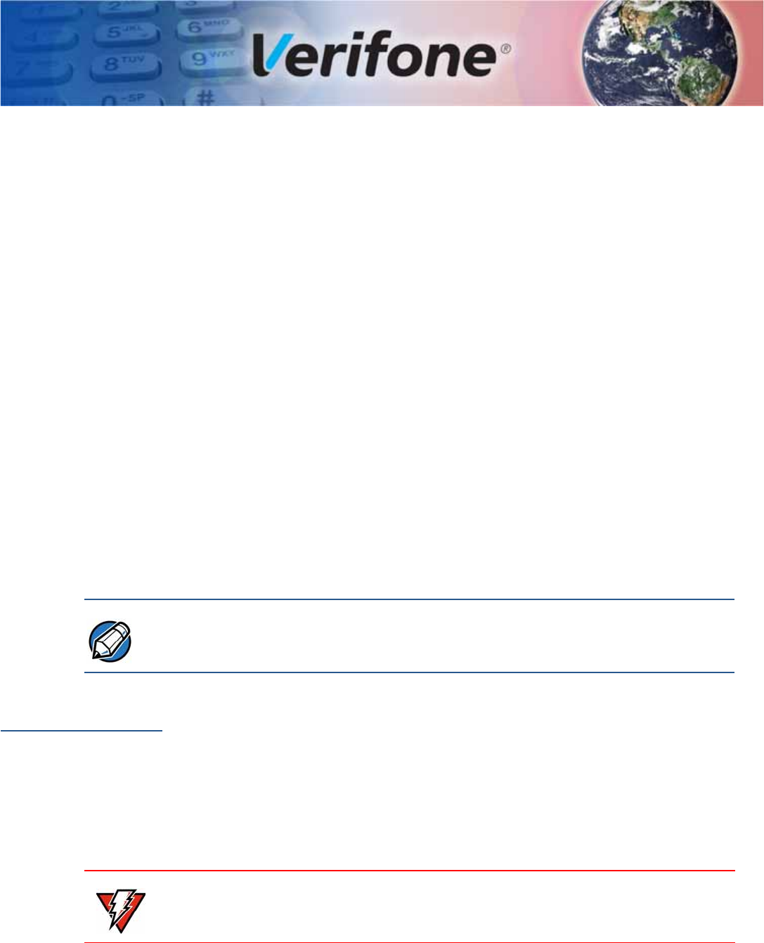
Unpacking
Shipping Carton Carefully inspect the shipping carton and its contents for possible tampering or
damage.
1Remove the V240m unit from the shipping carton. The standard package
contains the PIN pad, power pack, battery, and printer paper roll. Refer to
Accessories and Documentation for more information about V240m related
accessories.
Figure 6 V240m Box Contents
This device is a secure product and any tampering can cause it to cease to
function or operate in an unsecured manner.
2Remove any protective plastic wrap and place the unit on a table or
countertop.
3Remove the clear protective film from the display.
4Replace all the packing materials, close the lid, and save the carton for
repacking or moving the V240m unit or base in the future.
Do not use a unit that has been tampered with or otherwise damaged. This unit
comes equipped with tamper-evident label. If a label or component appears
damaged, immediately notify the shipping company and your Verifone
representative or service provider.
MSAM/uSD
Cards You may need to install or replace the multiple security access module (MSAM),
Micro Secure Digital (SD) and Subscriber Identity Module (SIM) cards.
Observe standard precautions in handling electrostatically sensitive devices.
Electrostatic discharges can damage the equipment. Verifone recommends using
a grounded anti-static wrist strap.
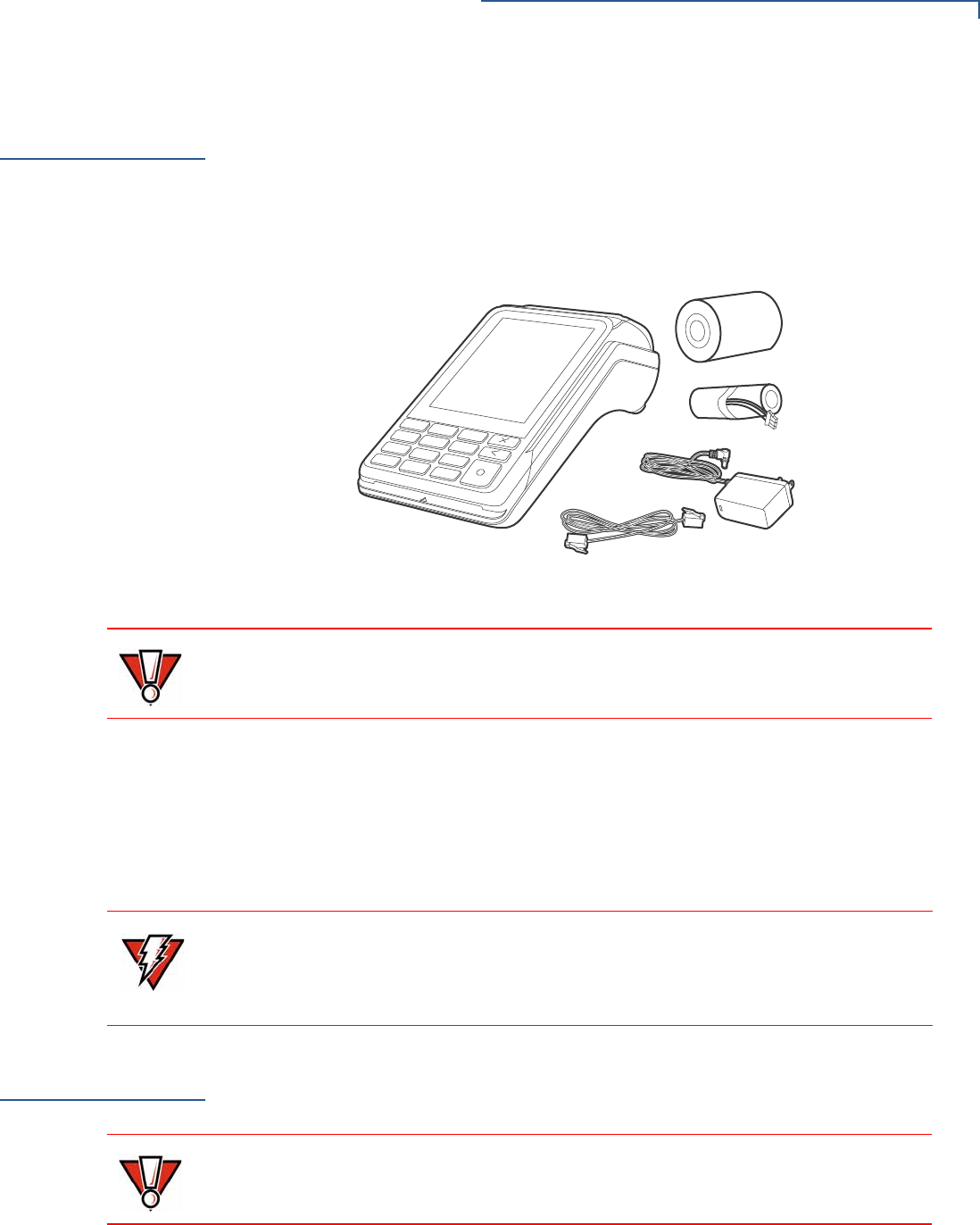
Opening Card
Compartment Use the following steps to get access to the MSAM, SD and SIM card
compartment:
CAUTION
WARNING
CAUTION
SETUP
MSAM/uSD Cards
16 V240M INSTALLATION GUIDE
1Place the terminal face down on a soft and clean surface to protect the display
from scratches.
2Push down the locking tab and swing out the compartment cover.
Figure 7 Opening Rear Compartment
3If it is installed, disconnect the battery and place in a secure location.
4The MSAM, SD and SIM cardholders are now accessible.
SIM 1
SAM 1
SAM 2
SIM 2
SD
Figure 8 V240m Card Holders
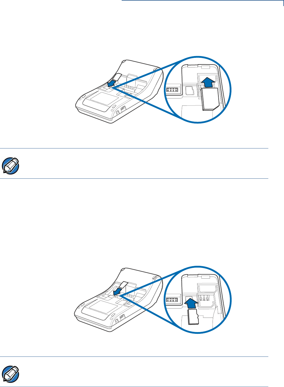
Changing or
Installing MSAMs To change or install MSAM cards:
1Use steps 1 to 3 of Opening Card Compartment to get to the MSAM
cardholder.
SETUP
MSAM/uSD Cards
V240M INSTALLATION GUIDE 17
2Remove the old card, if any, and install the MSAM card by carefully sliding it
into the slot (with the gold contacts facing downward) until fully inserted.
SIM 1
SAM 1
SD
3!-
Figure 9 Inserting MSAM Card
Insert the card with the card’s gold contacts facing away from you, toward the unit.
3If you are finished replacing or inserting cards, reconnect the battery and
replace the rear cover.
Changing or
Installing Micro SD
Card
To change or install Micro SD cards:
1Use steps 1 to 3 of Opening Card Compartment to get to the Micro SD
cardholder.
2Remove the old card, if any, and insert the Micro SD card by carefully sliding
it into the slot (with the gold contacts facing downward) until fully inserted.
SIM 1
SAM 1
SD
3$
Figure 10 Inserting Micro SD Card
Insert the card with the card’s gold contacts facing away from you, toward the unit.
3If you are finished replacing or inserting cards, reconnect the battery and
replace the rear cover.
NOTE
NOTE
SETUP
Loading Printer Paper
18 V240M INSTALLATION GUIDE
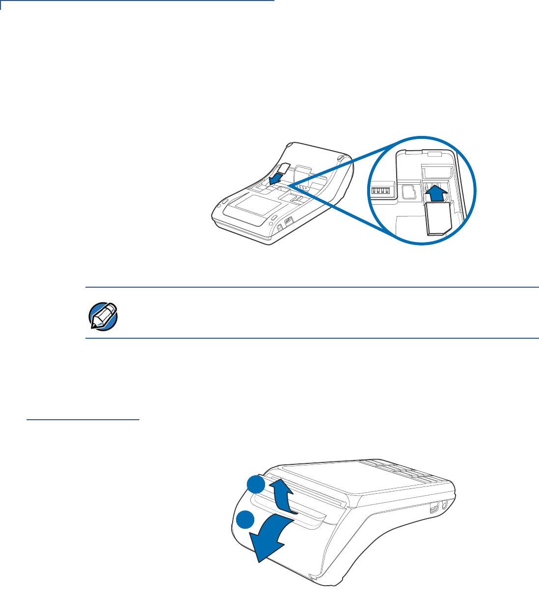
Changing or
Installing SIM Card To change or install SIM cards:
1Use steps 1 to 3 of Opening Card Compartment to get to the SIM cardholder.
2Remove the old card, if any, and insert the SIM card by carefully sliding it into
the slot (with the gold contacts facing downward) until fully inserted.
SIM 1
SAM 1
SD
3)-
Figure 11 Inserting SIM Card
Insert the card with the card’s gold contacts facing away from you, toward the unit.
3If you are finished replacing or inserting cards, reconnect the battery and
replace the rear cover.
Loading Printer
Paper
Use the following steps to load a roll of 57mm x 40mm thermal printer paper into
the compartment.
1Unlock the paper compartment by pulling up the latch and swinging the door
downwards.
1
2
Figure 12 Opening Printer Paper Door
NOTE
SETUP
Power Supply
V240M INSTALLATION GUIDE 19
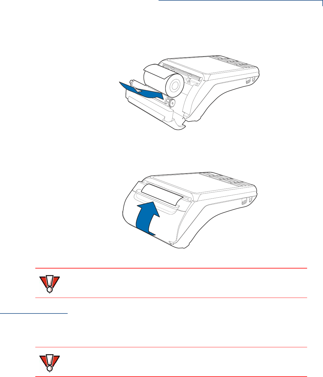
2Load the paper roll as shown in Figure 13, with the edge of the paper on the
top of the roll.
Figure 13 Procedure for Loading Paper Roll
3Pull a length of paper up over the serrated cutter and close the compartment
door.
Figure 14 Closing Printer Door
Before processing transactions in battery mode, make sure you have more than
10% battery life. Do not risk losing transaction data or printing capabilities,
connect the terminal to the power pack if battery level is below 10%.
Power Supply Not all configurations and device contexts require the use of a power supply –
Verifone ships power supply with the terminal as required.
Contact your Verifone representative If you have changed the context in which the
terminal is used or have questions about which power supply should be used.
Using an incorrectly rated power supply can damage the unit or cause it not to
work properly. Use only a power pack with VPN PWR474-002-01-A (see Service
and Support for detailed power supply specifications).
CAUTION
CAUTION
SETUP
Power Supply
20 V240M INSTALLATION GUIDE
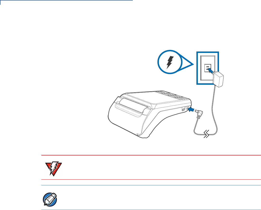
Disconnect the power pack cord from the power outlet before connecting a power
supply. Connect and route all cables between the terminal, ECR, and PC before
plugging the power pack cord into a wall outlet or surge protector.
Figure 15 Connecting the Power Pack
Do not plug the power pack into an outdoor outlet or operate the terminal
outdoors. Disconnecting power during a transaction can cause transaction data
files not yet stored in memory to be lost.
Verifone recommends installing a power surge protector to protect against
possible damage caused by lightning strikes and electrical surges.
When the terminal has power and an application is loaded, the application starts
after the initial Verifone copyright screen and displays a unique copyright screen.
If no application is loaded, DOWNLOAD NEEDED appears on the display after
the initial Verifone copyright screen.
WARNING
NOTE
SETUP
Cable Connections
V240M INSTALLATION GUIDE 21
USB Power Supply The V240m can be powered with 5 V supply from USB port (5 V at 1 A) with the
following power-saving conditions controlled by the OS:
•Micro-processor operating frequency is set to 300 MHz in CTLS mode.
•Switch off multi-media playback function when CTLS payment mode is
activated.
•Reduce audio output volume.
•LCD backlight intensity is reduced to 30% (not suitable for high-glare, outdoor
usage).
•Keypad backlight is disabled.
•BT and Wi-Fi functions are unavailable.
•Maximum audio output volume is reduced.
•Ethernet functionality is unavailable.
•Multi-media function (video playback or audio function) has to be switched off
by user or customer app when CTLS payment mode is activated. Other
modes of payment like smart card and MSR payment can be supported.
CTLS payment mode is defined as the state of the device where RF transmission
is broadcasting to allow for a CTLS payment. This is activated either during the
scanning of items or at the completion of scanning items during the checkout
process, depending on how the application sets it up. As soon as checkout is
complete, the device exits CTLS payment mode and remains off until activated for
the next checkout.
Cable
Connections
You can connect the V240m to peripherals using the Full-Function Base.
•
Turn off or unplug the terminal when connecting or disconnecting the device to
avoid device memory corruption and data loss.
Refer to the controlling device instructions for any terminal-specific warnings.
Cable Connections Using the Full-Feature Base
NOTE
WARNING
SETUP
Cable Connections
22 V240M INSTALLATION GUIDE
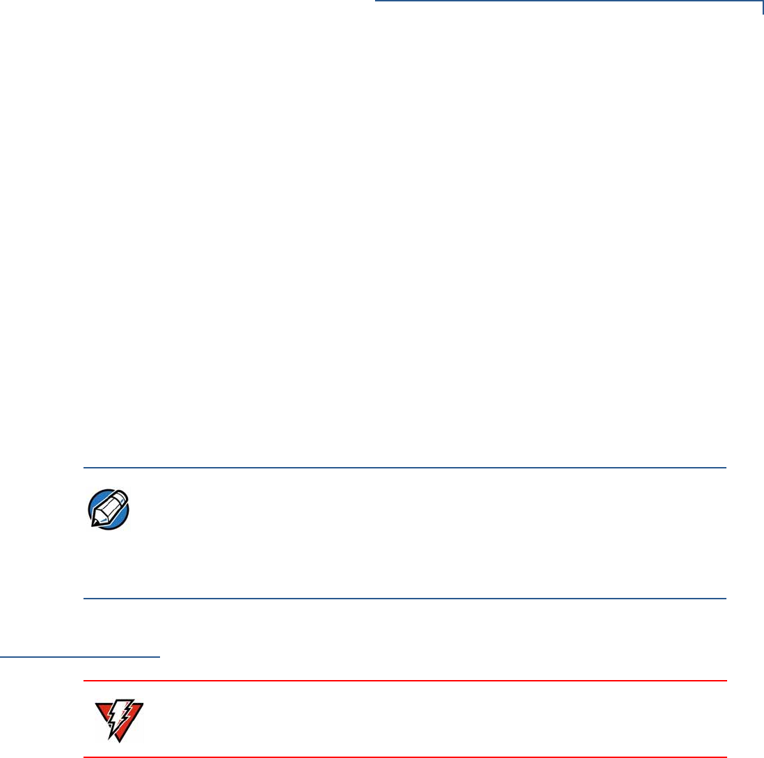
Cable Connections
Using the Full-
Feature Base
To connect the terminal to other devices via Ethernet, RS-232, and USB, use the
V240m Full-Feature (FF) Base. The FF Base provides a standard RJ-45 LAN
socket, RS-232 port, a mini-USB port. The V240m terminal must be docked on the
base to utilize cable connectivity
Figure 16 Full-Feature Base Peripheral Connections
SETUP
Smart Card Reader
V240M INSTALLATION GUIDE 23
The Full-Feature Base features the following:
Cable Configuration
Ethernet port RJ-45 socket (for connecting PINPad to LAN infrastructure)
RS232 port RS232 socket (for connecting PINPad to LAN infrastructure),
MOD-8 socket, Mini USB & DC-in jack
USB ports Mini USB and type A USB
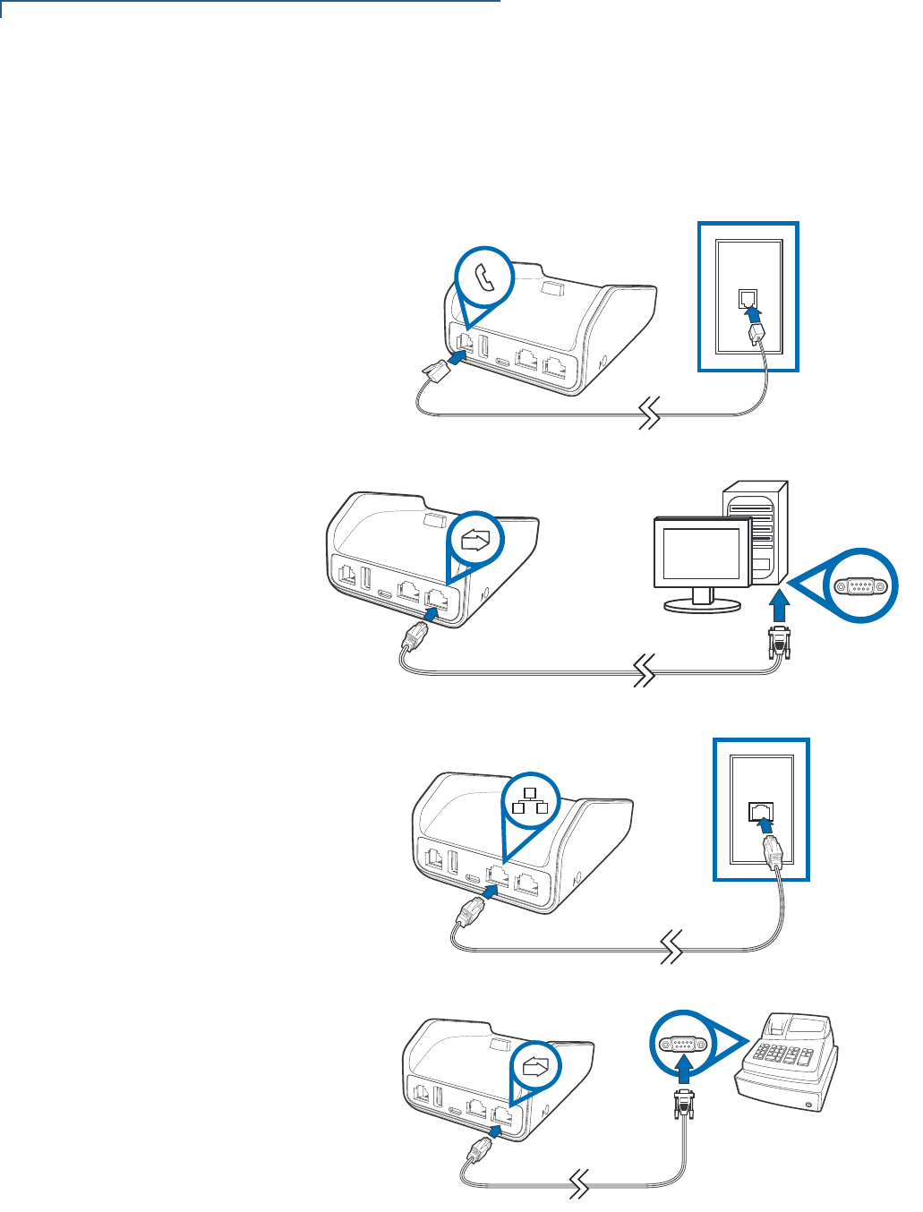
Smart Card
Reader
The smart card transaction procedure can vary depending on the application.
Verify the proper procedure with your application provider before performing a
smart card transaction.
Figure 17 Using the Smart Card Reader
Conducting a Smart
Card Transaction To conduct a smart card transaction:
1Position the smart card with the gold contacts facing upward.
2Insert the card into the smart card reader slot in a smooth, continuous motion
until it seats firmly.
3Remove the card when the display indicates the transaction is completed.
Leave the smart card in the card reader until the transaction is completed.
Premature removal can void the transaction.
CAUTION
SETUP
Magnetic Stripe Card Reader Use
24 V240M INSTALLATION GUIDE
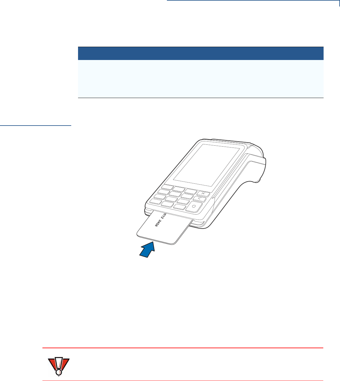
Magnetic Stripe
Card Reader Use
The V240m has a magnetic card reader that uses a triple track stripe reader. This
gives the unit greater reliability over a wide range of swipe speeds and operating
environments.
Figure 18 Using the Magnetic Stripe Card Reader
Conducting a Credit/
Debit Card
Transaction
To conduct a credit or debit card transaction:
1Position a magnetic card with the stripe facing the keypad.
2Swipe it through the magnetic card reader.
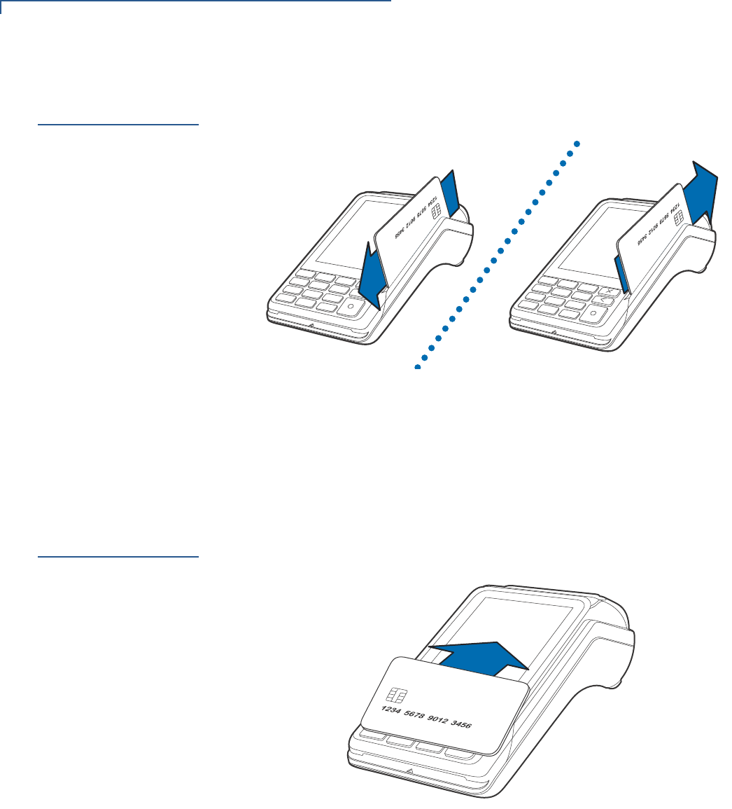
Contactless
Transactions
The V240m supports contactless transactions through an integrated contactless
module. The terminal only becomes active for contactless smart card transactions
when initialized by an application.
Figure 19 Contactless Transaction
Performing
Contactless
Transactions
To perform a contactless smart card transaction:
1Gently tap the card onto or hold the card (within 4 cm) against the surface of
the display where the contactless logo appears.
2An activated LED visual on the display accompanied by a short beeping sound
indicates a successful transaction.
See Contactless Considerations for more information.
SETUP
Camera / Barcode Scanner
V240M INSTALLATION GUIDE 25
Camera /
Barcode
Scanner
The V240m Camera variant includes an end-facing camera array that is capable
of barcode and QR code scanning.
Figure 20 V240m Camera array
Optional
Accessories
These accessories can be used to further enhance the device’s functionality. See
Accessories and Documentation for additional information.
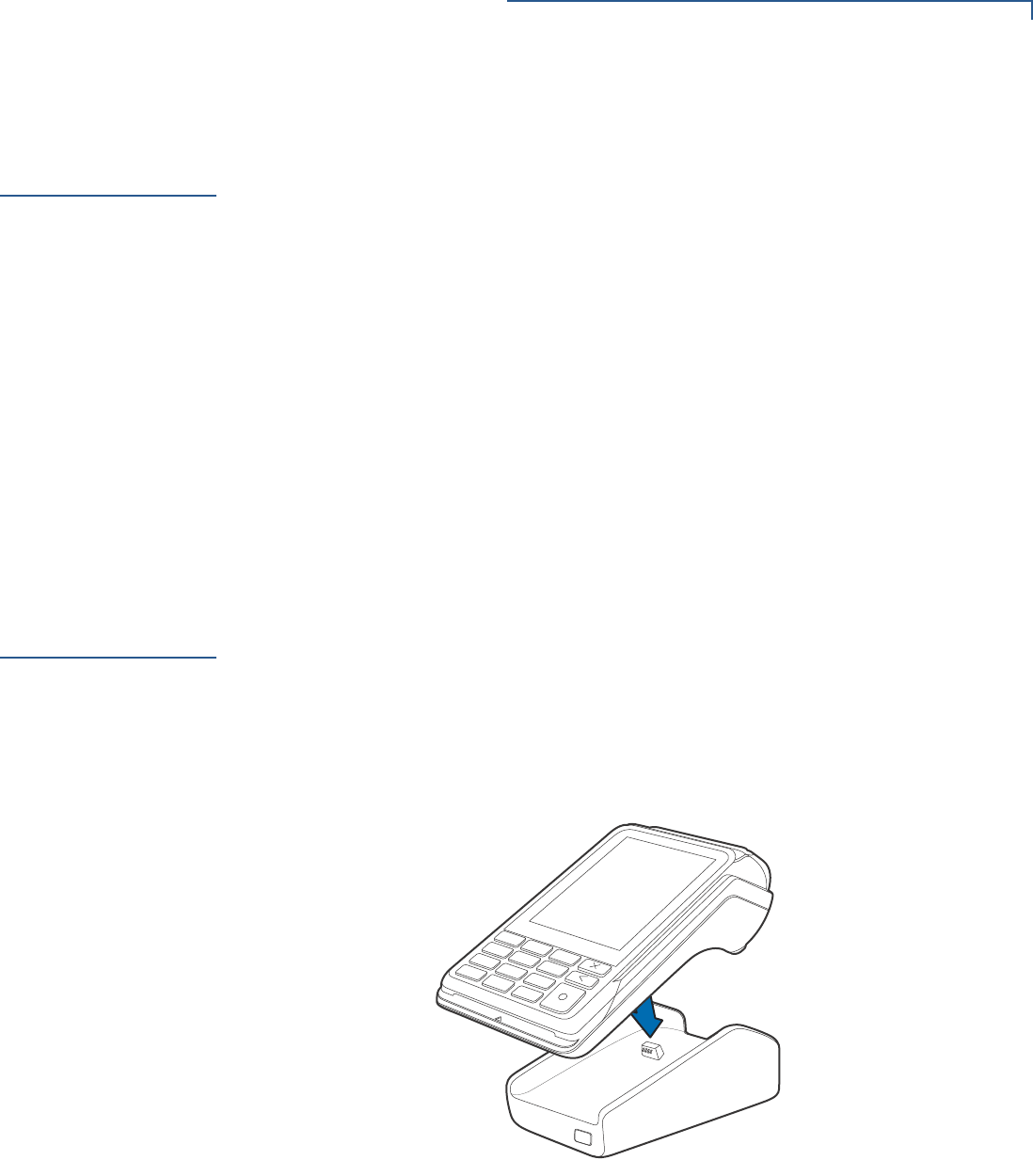
Full-Feature Base
The Full-Feature Base (VPN M474-S02-08) provides Bluetooth (BT) v4.2 as well as
All BT v4.1 features. It also supplies power, Dial up, Ethernet, USB Host and USB
Device, plus powered RS232 connection. See Cable Connections Using the Full-
Feature Base.
Figure 21 V240m Docking With Full-Feature Base
SETUP
Optional Accessories
26 V240M INSTALLATION GUIDE
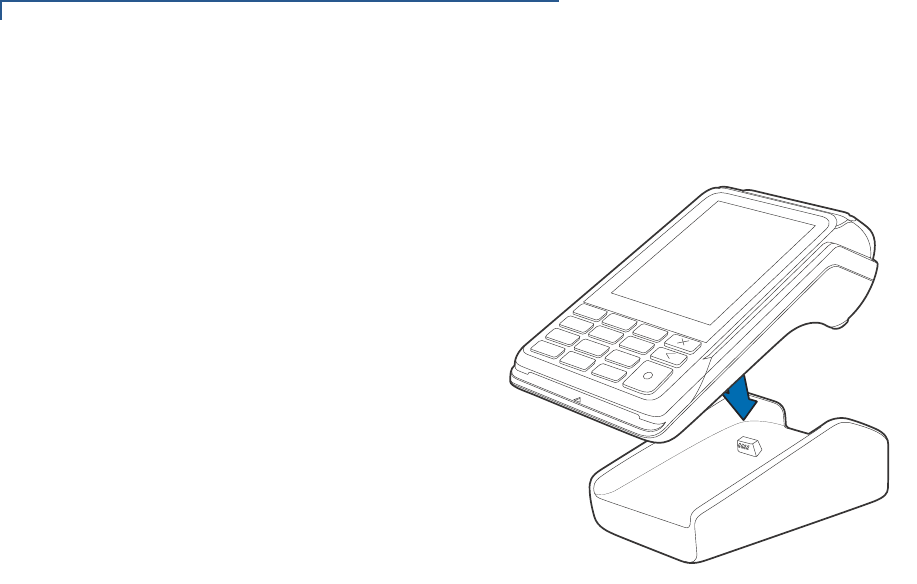
Charging Base
The Charging Base (VPN M474-S02-00) provides a stable dock plus power
charging for the V240m terminal.
Figure 22 V240m Docking With Charging Base

SETUP
Periodic Inspection
V240M INSTALLATION GUIDE 27
Periodic
Inspection Periodically inspect the terminal for possible tampering. Signs of tampering may
include:
•Wires protruding from the device.
•Foreign objects inserted into the smart card or mag stripe slot.
•Signs of damage to the tamper-evident label.
•Warning message on the device display.
If any device is found in tamper state, please remove it immediately from service.
Keep it available for potential forensic investigation, and notify your company
security officer and your local Verifone representative or service provider. For
more information on contacting Verifone, refer to Service and Support.
NOTE

SETUP
Periodic Inspection
28 V240M INSTALLATION GUIDE

V240M INSTALLATION GUIDE 29
CHAPTER 3
Specifications
This chapter discusses power requirements, dimensions, and other specifications
of the V240m terminal and bases.
V240m Terminal Refer to the following specifications for the V240m terminal:
Unit Power
Requirements V240m devices have the following power requirements:
•Operating Power: V240m
5 V DC, 1A
V240m Camera
5 V DC, 1A/2.2A
Temperature •Operating temperature: 0° to 50° C (32° to 122° F)
•Storage temperature: -20° to 60° C (-4° to 140° F)
Humidity •Relative humidity: 5% to 90% (RH non-condensing)
External
Dimensions V240m V240m Camera
•Length: 162.9 mm (6.4 in) 172.4 mm (6.8 in)
•Width: 75.3 mm (2.9 in) 75.3 mm (2.9 in)
•Depth: 53.4 mm (2.1 in) 53.4 mm (2.1 in)
Weight •Unit weight: V240m
320 g (11.28 oz)
V240m Camera
330 g (11.64 oz)
Processor •ARM Cortex A9 32-bit processor
Display •3.5” portrait mode transmissive TFT 320 (RGB) x 480 (HVGA)
Magnetic Card
Reader •Triple track (tracks 1, 2, 3), high coercivity, bi-directional
Primary Smart Card •ISO 7816-3, 1.8 V, 3 V, 5 V
•Synchronous and Asynchronous cards
•EMV Approved
/ 2.2A

SPECIFICATIONS
V240m Bases
30 V240M INSTALLATION GUIDE
SAM Card Reader •Two Security Access Modules (SAMs)
Battery Pack •Rating: 9.1 Wh (3.7 V DC, 2450 mAH)
•Meets IEEE1725 requirements
Security •3DES encryption, Master/Session and DUKPT key management
•VeriShield file authentication
•PCI PED 5.x approved
V240m Bases Charging Base
•Provides terminal charging on a mounted stand
Full-Feature Base
•Aside from charging, the FF Base provides:
•Bluetooth
•10/100M Ethernet
•56K modem
•Powered RS-232
•LE Secure feature of BT v4.2 + All BT v4.1 feature
•USB host
•USB device
Unit Power
Requirements •Operating Power: 5 V DC, 2.2 A (FF Base)
5 V DC 1 A (Charging Base)
Temperature •Operating temperature: -5° to 50° C (23° to 122° F)
•Storage temperature: -20° to 60° C (-4° to 140° F)
Humidity •Relative humidity: 5% to 95% (RH non-condensing)
Security •PCI 5.x Compliant.

V240M INSTALLATION GUIDE 31
CHAPTER 4
Troubleshooting
Guidelines
This chapter lists typical malfunctions that may occur while operating a V240m
device and the appropriate corrective action. If the problem persists – even after
performing the outlined guidelines, or if the problem is not described, contact your
local Verifone representative for assistance.
The V240m device uses a tamper-evident case and contains no user-serviceable
parts. Do not, under any circumstance, attempt to disassemble the unit. Perform
only those adjustments or repairs specified in this guide. For all other services,
contact your local Verifone service provider. Service conducted by parties other
than authorized Verifone representatives may void any warranty.
Display Panel
Does Not Work Use the following steps to check the display panel:
1Check all the cable connections.
2Check the controlling device's AC outlet to be sure the outlet is supplying
sufficient power. Substitute the controlling device's power pack with another
power pack.
3The controlling device's application program might not be loaded correctly.
Download the application program and try again.
4If the problem persists, contact your local Verifone representative.
Keypad Does
Not Respond Use the following steps to check the keypad:
1Check the display panel. If there are no characters, or the wrong characters
are displayed, refer to Display Panel Does Not Work.
2If the problem persists, contact your local Verifone representative.
Transactions
Fail To Process There are several possible reasons why the unit may not be processing
transactions. Use the following steps to troubleshoot failures.
Check Magnetic Card Reader
•Perform a test transaction using one or more different magnetic stripe cards to
ensure the problem is not a defective card.
•Ensure that you are swiping cards properly (see Magnetic Stripe Card Reader
Use).
•Process a transaction manually using the keypad instead of the card reader. If
the manual transaction works, the problem may be a defective card reader.
NOTE

TROUBLESHOOTING GUIDELINES
Transactions Fail To Process
32 V240M INSTALLATION GUIDE
•If the problem persists, contact your local Verifone representative.
Check Smart Card Reader
•Perform a test transaction using several different smart cards to ensure the
problem is not a defective card.
•Ensure that the card is inserted correctly (see Magnetic Stripe Card Reader
Use).
•Ensure the MSAM cards are properly inserted in the slots and are properly
secured (see MSAM/uSD Cards).
•If the problem persists, contact your local Verifone representative.
V240M INSTALLATION GUIDE 33
CHAPTER 5
Service and Support
Maintenance
and Cleaning The V240m device has no user-serviceable parts. Unless otherwise instructed, do
not, under any circumstances, attempt any service, adjustments, or repairs on the
unit. Disconnect the device before cleaning.
To clean the unit, periodically use a clean cloth, slightly dampened with water and
a drop or two of mild soap. For stubborn stains, use alcohol or an alcohol-based
cleaner. For best results, use a Verifone Cleaning Kit (refer to Accessories and
Documentation).
Never use thinner, trichloroethylene, or ketone-based solvents – they can
deteriorate plastic or rubber parts.
Because the V240m can be damaged by liquid, do not spray cleaners or other
solutions directly onto the keypad or display. Always apply the cleaner to a cloth
before cleaning the device.
Service Returns For V240m equipment failures that cannot be resolved by your help desk or
service department, contact one of the following hotlines for product service and
repair information:
•USA – Verifone Service and Support Group, 1-800-834-9133,
Monday - Friday, 8 A.M. - 7 P.M., EST
•International – Contact your Verifone representative
Before returning V240m unit to Verifone, you must obtain a Merchandise Return
Authorization (MRA) number. The following procedure describes how to return
one or more V240m for repair or replacement (U.S. customers only).
International customers, please contact your local Verifone representative for
assistance with your service, return, or replacement.
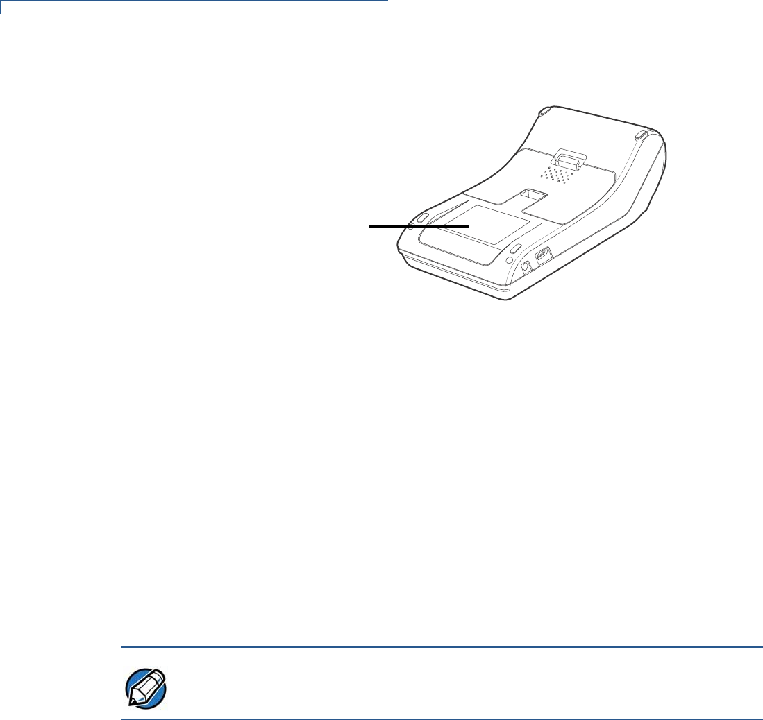
1Gather the following information from the printed labels on the bottom of each
V240m device to be returned:
•Product ID, including the model and part number. For example,
“M474-xxx-xx-xxx-x”
CAUTION
NOTE
SERVICE AND SUPPORT
Service Returns
34 V240M INSTALLATION GUIDE
•Serial number (S/N xxx-xxx-xxx)
PRODUCT ID &
SERIAL NUMBER
Figure 22 Product ID and Serial Number Location
2Within the United States, call Verifone toll-free at 1-800-834-9133.
3Select the MRA option from the automated message. The MRA department is
open Monday–Friday, 8 A.M.–7 P.M., EST.
4Give the MRA representative the information gathered in Step 1.
If the list of serial numbers is long, you can fax the list, along with the
information gathered in Step 1, to the MRA department at 1-727-953-4172
(U.S.)
•Please address the fax clearly to the attention of the
“Verifone MRA Dept.”
•Include a telephone number where you can be reached, as well as your
fax number.
•You will be issued MRA number(s) and the fax will be returned to you.
One MRA number must be issued for each V240m unit you return to Verifone,
even if you are returning several of the same model.
5Describe the problem(s).
6Provide the shipping address where the repaired or replacement unit must be
returned.
7Keep a record of the following items:
•Assigned MRA number(s).
•The serial number assigned to the V240m device (located at the bottom of
the unit.
•Shipping documentation, such as air bill numbers, used to trace the
shipment.
•Model(s) returned (model numbers are located on the bottom of the unit).
NOTE

SERVICE AND SUPPORT
Accessories and Documentation
V240M INSTALLATION GUIDE 35
Accessories and
Documentation Verifone produces accessories and documentation for the V240m. When
ordering, please refer to the part number in the left column.
•Verifone Online Store at www.store.verifone.com
•USA – Verifone Customer Development Center, 1-800-Verifone (837-4366)
Monday - Friday, 7 A.M. - 5 P.M., MST
•International – Contact your Verifone representative
Cables Contact your local Verifone distributor to determine which cable fits your needs.
CBL280-025-02-A USB Cable 4.1 m
CBL282-045-XX-A USB cable (as Device). Powered from +9 V/1 A DC adaptor
CBL282-038-XX-A USB cable (as Device). Powered from +5 V USB Host.
CBL282-033-01-A Powered USB cable (as Device). Powered from +12 V PUSB
Host
CBL282-031-XX-A RS-232 cable (DB9). Powered from +12 V DC adaptor.
CBL282-036-XX-A RS-232 cable (RJ45). Powered from Countertop (+12 V).
CBL282-006-01-B Cable, VX 820 Ethernet/RS232, Dongle 1.0 m
Power Supply PWR474-002-01-A DC power pack
Accessories 02746-01 Verifone Cleaning Kit
Documentation DOC474-001-EN V240m Certifications and Regulations
DOC474-002-EN V240m Quick Installation Guide

SERVICE AND SUPPORT
Accessories and Documentation
36 V240M INSTALLATION GUIDE

V240M INSTALLATION GUIDE 37
APPENDIX A
Caution and
Warning
Messages
Products with UL/cUL certification should include French translations of Caution
and Warning notices. The following table lists all notices found in the document,
their location, and the equivalent French translations.
Table 3 Caution and Warning Messages
Notice Chapter Page English Text French Text
Warning Setup page
13 For safety, do not string cables or
cords across a walkway. Par mesure de sécurité, ne pas les câbles de
chaîne ou de cordons à travers une
passerelle.
Caution Setup page
14 This unit is not waterproof or
dustproof, and is intended for
indoor use only. Any damage to
the unit from exposure to rain or
dust can void any warranty.
Cet appareil n'est pas étanche ou à la
poussière, et est destiné à une utilisation en
intérieur. Tout dommage à l'unité de
l'exposition à la pluie ou à la poussière peut
annuler la garantie.
Caution Setup page
14, Using an enclosed metal frame or
mount may negatively affect
contactless performance.
L'utilisation d'un cadre métallique fermé ou de
montage peut affecter négativement contact
performance.
Warning Setup page
14 Due to risk of electrical shock or
terminal damage, do not use the
terminal near water, including a
bathtub, wash bowl, kitchen sink
or laundry tub, in a wet basement,
or near a swimming pool. Also,
avoid using this product during
electrical storms. Avoid locations
near electrical appliances or other
devices that cause excessive
voltage fluctuations or emit
electrical noise (for example, air
conditioners, neon signs,
highfrequency or magnetic
security devices, or electric
motors).
Du fait d'un risque d'électrocution ou d'une
détérioration du terminal, ne pas utiliser cet
équipement près d'une source d'eau, par
exemple près d'une baignoire, d'un lavabo,
d'un évier de cuisine ou d'un bac de lavage,
dans un sous-sol humide ou à proximité d'une
piscine. De même, éviter d’utiliser ce produit
lors des orages provoquant des coupures
électriques.Éviter de placer le terminal à
proximité d’appareils électriques ou autres
unités pouvant entraîner des fluctuations de
tension importantes ou des interférences
électriques, tels que les climatiseurs,
enseignes au néon, dispositifs de sécurité à
haute fréquence ou équipements électriques.
Caution Setup page
15 This device is a secure product
and any tampering can cause it to
cease to function or operate in an
unsecured manner.
Cet appareil est un produit sûr et toute
manipulation peut l'amener à cesser de
fonctionner ou fonctionner de manière non
sécurisée.

Caution and Warning Messages
38 V240M INSTALLATION GUIDE
Warning Setup page
15 Do not use a unit that has been
tampered with or otherwise
damaged. This unit comes
equipped with tamper-evident
label. If a label or component
appears damaged, immediately
notify the shipping company and
your Verifone representative or
service provider.
Ne pas utiliser un appareil qui a été altéré ou
endommagé. Cet appareil est équipé
d'étiquette d'inviolabilité. Si une étiquette ou
d'un composant semble être endommagé, en
aviser immédiatement la compagnie maritime
et votre représentant Verifone ou prestataire
de services.
Caution Setup page
15 Observe standard precautions in
handling electrostatically sensitive
devices. Electrostatic discharges
can damage the equipment.
Verifone recommends using a
grounded anti-static wrist strap.
Respecter les précautions standard dans la
manipulation d'appareils sensibles aux
décharges électrostatiques. Les décharges
électrostatiques peuvent endommager le
matériel. Verifone recommande d'utiliser un
bracelet anti-statique à la terre.
Caution Setup page
19 Using an incorrectly rated power
supply can damage the unit or
cause it not to work properly. Use
only a power pack with VPN
PWR474-002-01-A.
L'utilisation d'une alimentation incorrecte peut
endommager l'appareil ou ne pas fonctionner
correctement. Utilisez uniquement un bloc
d'alimentation avec VPN PWR474-002-01-A.
Caution Setup page
20 Do not plug the power pack into
an outdoor outlet or operate the
terminal outdoors. Disconnecting
power during a transaction can
cause transaction data files not
yet stored in memory to be lost.
Ne branchez pas le bloc d'alimentation dans
une prise extérieure ou n'utilisez pas le
terminal à l'extérieur. La déconnexion de
l'alimentation pendant une transaction peut
entraîner la perte des fichiers de données de
transaction qui ne sont pas encore stockés
dans la mémoire.
Warning Setup page
21 Turn off or unplug the terminal
when connecting or disconnecting
the device to avoid device
memory corruption and data loss.
Refer to the controlling device
instructions for any terminal-
specific warnings.
Éteignez ou débranchez le terminal pour
connecter ou déconnecter le dispositif pour
éviter la corruption de la mémoire de
l'appareil et la perte de données. Reportez-
vous aux instructions de l'appareil de contrôle
pour tous les avertissements spécifiques au
terminal.
Table 3 Caution and Warning Messages (continued)
Notice Chapter Page English Text French Text

Caution and Warning Messages
V240M INSTALLATION GUIDE 39
Caution Setup page
23 Leave the smart card in the card
reader until the transaction is
completed. Premature removal
can void the transaction.
Laissez la carte à puce dans le lecteur de
carte jusqu'à ce que la transaction soit
terminée. Le retrait prématuré peut annuler la
transaction.
Caution Service
and
Support
page
33 Never use thinner,
trichloroethylene, or ketone-
based solvents – they can
deteriorate plastic or rubber parts.
Because this device can be
damaged by liquid, do not spray
cleaners or other solutions
directly onto the keypad or
display. Always apply the cleaner
to a cloth before cleaning the
device.
N'utilisez jamais de diluant, le trichloréthylène
ou des solvants cétoniques - ils peuvent
détériorer les pièces en plastique ou en
caoutchouc. Parce que cet appareil peut être
endommagé par un liquide, ne pas vaporiser
de nettoyage ou d'autres solutions
directement sur le clavier ou l'écran. Toujours
appliquer le nettoyant sur un chiffon avant de
nettoyer l'appareil.
Table 3 Caution and Warning Messages (continued)
Notice Chapter Page English Text French Text

Caution and Warning Messages
40 V240M INSTALLATION GUIDE


FCC Regulations:
This device complies with part 15 of the FCC Rules. Operation is subject to the following two conditions: (1) This device
may not cause harmful interference, and (2) this device must accept any interference received, including interference
that may cause undesired operation.
Changes or modifications not expressly approved by the party responsible for compliance could void the user‘s
authority to operate the equipment.
This equipment has been tested and found to comply with the limits for a Class B digital device, pursuant to part 15 of
the FCC Rules. These limits are designed to provide reasonable protection against harmful interference in a residential
installation. This equipment generates, uses and can radiate radio frequency energy and, if not installed and used in
accordance with the instructions, may cause harmful interference to radio communications. However, there is no
guarantee that interference will not occur in a particular installation. If this equipment does cause harmful interference
to radio or television reception, which can be determined by turning the equipment off and on, the user is encouraged
to try to correct the interference by one or more of the following measures:
—Reorient or relocate the receiving antenna.
—Increase the separation between the equipment and receiver.
—Connect the equipment into an outlet on a circuit different from that to which the receiver is connected.
—Consult the dealer or an experienced radio/TV technician for help.