Wayne Dalton 0001715 TORQUE MASTER i-DRIVE PRO User Manual INSTALLATION GUIDE 1
Wayne Dalton Corporation TORQUE MASTER i-DRIVE PRO INSTALLATION GUIDE 1
Contents
- 1. INSTALLATION GUIDE 1
- 2. INSTALLATION GUIDE 2
- 3. INSTALLATION GUIDE 3
- 4. INSTALLATION GUIDE 4
INSTALLATION GUIDE 1

5015 B.U. Bowman Drive Buford, GA 30518 USA Voice: 770-831-8048 Fax: 770-831-8598
Certification Test Report
908.42 MHz Low Power Communication Device Transceiver
372 MHz Discrete Receiver
FCC ID: KJ8-0001715
IC: 3540A-0001715
FCC Rule Part: 15.249
IC Radio Standards Specification: RSS-210
ACS Report Number: 07-0186 - 15C
Manufacturer: Wayne-Dalton Corporation
Model: 3790-Z
Installation Guide
Section1

INSTALLATION INSTRUCTIONS AND OWNER’S MANUAL
Models: 3790/3790-Z/3791/3791-Z
Installation Instructions
and Owner’s Manual
USE OF THIS MANUAL
WHEN INSTALLING A NEW DOOR WITH AN IDRIVE®:
If you just fi nished installing a new garage door along with
an idrive® opener, then proceed with these instructions
beginning with Step 15 on page 22. If you were referred to
these instructions as part of a new door installation, then
proceed with these instructions beginning with Step 1 on
page 7.
for TORQUEMASTER®/
TORQUEMASTER® PLUS
FPO
Intergrated Z-Wave® technology
Ready for your home
control network
On select models
FPO
IMPORTANT NOTICE!
To avoid possible injury, read the enclosed instructions carefully
before installing/operating this garage door opener. Pay close
attention to all warnings and notes. This manual MUST be attached
to the wall in close proximity to the garage door opener.
Copyright 2007 Wayne-Dalton Corp. Part No. XXXXXX New 9/7/2007
GARAGE DOORS & OPENERS
T
o
O
p
e
r
a
t
e
D
o
o
r
Press
Here
9 0
7 8
5 6
3 4
1 2
S1 S2 S3 S4
Learn Delete
Controls
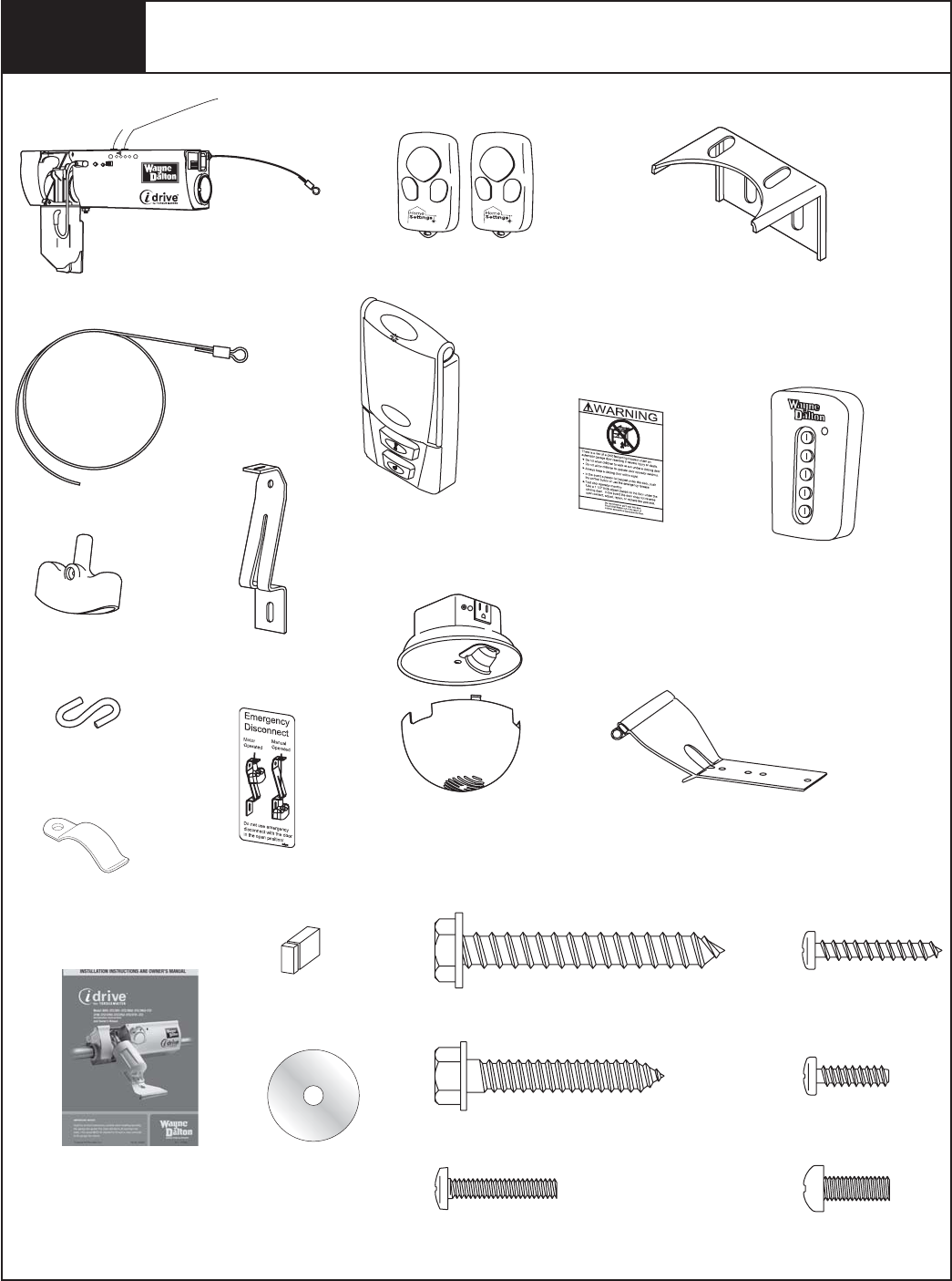
Package Contents
Key chain/Visor
Transmitter (2)
Opener
Deluxe Multi-function
Wireless Wall Station
Security Light with
Diffuser
Disconnect Handle
Disconnect
Handle Bracket
“S” Hook
1/4” x 1-1/2" Hex Head
Lag Screws (4)
#6 x 7/8" Phillips Pan
Head Screws (4)
Disconnect Cable
1/4” x 2" Hex Head Lag
Screws (2)
Owner’s Manual
Emergency
Disconnect Label
Installation DVD
Entrapment Label
5 Button Wireless
Keyless Entry
#6-20 x 1/2" Phillips
Pan Head Screw (1)
Lock Arm Assembly
Cable Clips (4)
#6-32 x 3/4" Phillips Pan Head
Screw (1)
(For Light Fixture)
5mm x .8mm x 12mm
Phillips Pan Head Screw (1)
(For Lock Arm)
Mounting Bracket
IPlease Do Not Return This Product To The Store. Call Us Directly! Our Trained Technicians Will Answer Your Questions and/or Ship Any Parts You May Need.
You can reach us Toll Free at 1-888-827-3667 for Consumer Assistance or online at www.wayne-dalton.com
Jumper
(Optional for Safety Sensors)
FPO

PRE-INSTALLATION INSPECTION OF YOUR GARAGE DOOR
PRIOR TO TORQUEMASTER® IDRIVE® INSTALLATION
Congratulations, you have just purchased one of the world’s safest garage door openers! By
design, this opener will detect obstructions and reverse rather than force the door through
obstructions. To ensure your new idrive® opener works as intended, your garage door must be
installed and balanced properly.
WHEN INSTALLING A NEW DOOR WITH AN IDRIVE®:
If you just nished installing a new garage door along with an idrive® opener, then proceed with
these instructions beginning with Step 15 on page 22. If you were referred to these instructions
as part of a new door installation, then proceed with these instructions beginning with Step 1
on page 7.
WHEN INSTALLING AN IDRIVE® ON AN EXISTING DOOR WITH TORQUEMASTER® OR
TORQUEMASTER® PLUS:
Before installing the idrive® opener, open and close you door manually to ensure that it
operates smoothly from top to bottom. A properly balanced door should not take a lot of effort
to open or close by hand. The door should stay in the open and in the closed position without
drifting down or creeping up. If a door opens fast going up, the door may need spring tension
reduced. If the door drops fast going down, the door may need spring tension increased.
If the operation of the door does not meet these criteria, you need to adjust the spring balance
per your door’s Installation Instructions and Owner’s Manual or call a professional installer to
make adjustments before installing idrive®.
If the door operates properly, check and record your Torquemaster® counterbalance spring
settings (for Torquemaster Plus spring settings, see warning tag(s) attached to the end
brackets or refer to your door Installation Instructions and Owner’s manual). Then proceed
with unwinding of the spring(s) for installation of your idrive®, carefully following the
instructions in STEP R1 of your idrive® Installation Instructions and Owner’s Manual. After the
idrive® is installed on the Torquemaster® tube, rewind the Torquemaster® or Torquemaster® Plus
to the previously recorded settings.
Instruction manuals are available for download on www.wayne-dalton.com. Use the web site
to also nd the location of your nearest professional dealer.
Check out the new idrive® installation video at www.wayne-dalton.com
Idrive® for Torquemaster®
http://www.wayne-dalton.com/idrive_TorqueMaster.asp
Look for this symbol.
II Please Do Not Return This Product To The Store. Call Us Directly! Our Trained Technicians Will Answer Your Questions and/or Ship Any Parts You May Need.
You can reach us Toll Free at 1-888-827-3667 for Consumer Assistance or online at www.wayne-dalton.com
S1 S2 S3 S4
Learn Delete
Controls
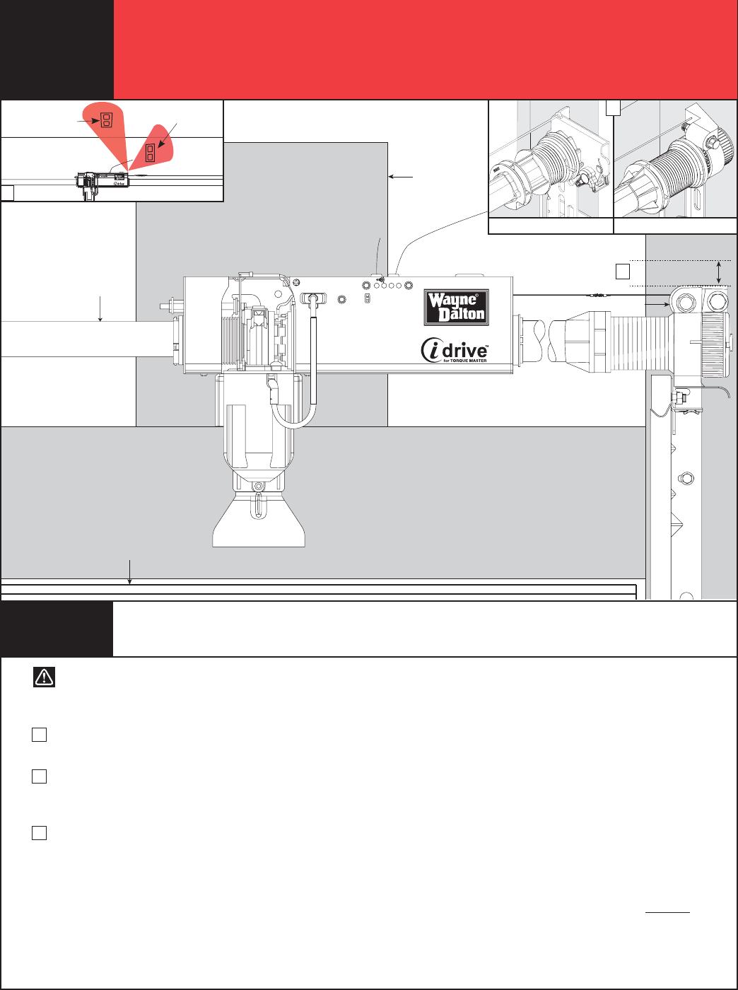
Torque Tube
1” Clearance for Motor
Top of
Door
End Bracket
Mounting Surface
Electrical outlet on the
wall is for opener
Electrical outlet on
the ceiling is for
light/opener
Pre-Installation Inspection
A. You must have a Wayne-Dalton Torquemaster® or Torquemaster®
Plus counterbalance system to install this opener (see A above).
B. The motor requires 1" of clearance above the top of the end
bracket for Torquemaster and 1-1/4” of clearance above the top
of the end bracket for Torquemaster plus.
C. Two electrical outlets are recommended for the idrive®
installation. One of these outlets needs to be located less than 6'
from the opener. The second outlet, for the light, can be located
at a position of your choice.
If, in the event that an electrical outlet is not located within 6' of
the opener, contact a local electrician for further options. As a
convenience, an electrical outlet is provided on the light fixture.
The 6’ opener cord can be used with this outlet.
D. Your door must not exceed 8' in height.
E. The idrive® opener will only work on sectional doors. Do not
install on one-piece doors.
F. Your garage door must be properly balanced (door must not be
heavy to lift, nor lift by itself).
G. Horizontal tracks should be raised 1" above level at rear of Track.
H. We do not recommend installing the idrive® opener on
Model 9700 door widths of 16’ - 18’.
I. Maximum door weight (without spring tension) must not
exceed 225 lb.
CAUTION: DO NOT INSTALL THIS OPENER ON YOUR DOOR UNLESS THE FOLLOWING REQUIREMENTS ARE MET.
USE THE ILLUSTRATION ABOVE AS A VISUAL AID.
III
Please Do Not Return This Product To The Store. Call Us Directly! Our Trained Technicians Will Answer Your Questions and/or Ship Any Parts You May Need.
You can reach us Toll Free at 1-888-827-3667 for Consumer Assistance or online at www.wayne-dalton.com
PRE-INSTALLATION INSPECTION
CAUTION! Do not install this opener on your door unless
the following requirements are met.
C
B
A
Torquemaster® Plus Torquemaster®
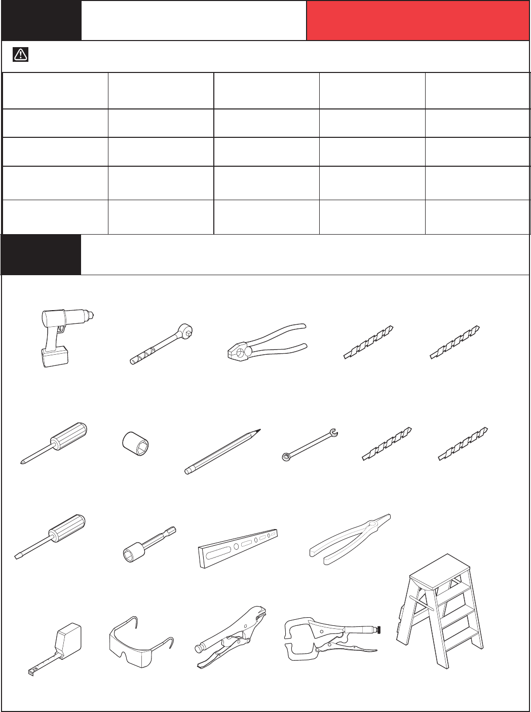
Safety Glasses
Phillips Head
Screwdriver
Step Ladder
Ratchet Wrench
7/16” Wrench 5/64” Drill Bit
3/16” Drill Bit
1/8” Drill Bit7/16” Socket
Flat Tip
Screwdriver
Needle Nose Pliers
Level7/16” Socket Driver
Pliers/Wire
Cutters
3/32” Drill Bit
Tape Measure
Pencil
Power Drill
CAUTION TO REDUCE THE RISK OF INJURY, USE THIS OPENER ONLY WITH THE FOLLOWING DOOR MODELS:
System Requirements
Locking Pliers
WAYNE-DALTON
DOOR MODEL
WAYNE-DALTON
SPRING SYSTEM TRACK (RADIUS) PHOTOELECTRIC
SAFETY SENSORS
LOW HEAD
ROOM KIT
9000 SERIES Torquemaster®
Torquemaster® Plus 10",12",14",15" Not Required Not Required
9000 SERIES Torquemaster®
Torquemaster® Plus 6" Low Head Room Not Required P/N 302883
Required
8000 SERIES Torquemaster®
Torquemaster® Plus 10",12",14",15" P/N’s 252118 or
301674 Required Not Required
8000 SERIES Torquemaster®
Torquemaster® Plus 6" Low Head Room P/N’s 252118 or
301674 Required
P/N 302883
Required
IV
Please Do Not Return This Product To The Store. Call Us Directly! Our Trained Technicians Will Answer Your Questions and/or Ship Any Parts You May Need.
You can reach us Toll Free at 1-888-827-3667 for Consumer Assistance or online at www.wayne-dalton.com
Vice Clamps
Tools Needed

Table of Contents
Package Contents ............................................................................... I.
Pre-Installation Inspection ................................................................... II, III
Tools Needed ...................................................................................... IV.
Important Safety Instructions .............................................................. V.
Retro-Fit Installations .......................................................................... 1-6.
idrive® for Torquemaster® Installation ................................................. 7-22.
Pre-Operation ...................................................................................... 22-33.
Operation ............................................................................................ 34-39.
Maintenance ....................................................................................... 39.
Programming Wireless Wall Stations or Transmitters to Opener .......... 41.
Troubleshooting ................................................................................... 42-43.
Warranty ............................................................................................. 44.
Customer Service Number .................................................................. 45.
INCORRECT INSTALLATION CAN
LEAD TO SEVERE OR FATAL
INJURY. FOLLOW THESE
INSTRUCTIONS CAREFULLY.
IMPORTANT SAFETY
INSTRUCTIONS
1. READ AND FOLLOW ALL INSTALLATION INSTRUCTIONS.
2. Do not connect the opener to electrical power until instructed
to do so.
3. Install the entrapment warning label next to the wall station in
a prominent location. Install the emergency disconnect label
next to the emergency disconnect.
4. Remove all ropes and remove, or make inoperative in the unlocked
position, all locks connected to the garage door before installing
the opener.
5. Do not wear rings, watches or loose clothing when installing
or servicing a garage door system.
6. It is important that you install all the components supplied with the
idrive® opener, i.e., wall stations, safety sensors, etc. Use
of parts not supplied by Wayne-Dalton Corp. may cause the
opener to malfunction and create unsafe conditions.
7. Wear safety glasses for eye protection when installing or servicing
the opener or door.
8. Install opener on a properly balanced and operating garage
door. Have a qualified service person make adjustments/repairs
to cables, spring assemblies, and other hardware before
installing the opener. An improperly balanced door could
cause severe injury.
9. Where possible, install the opener seven feet or more above the
floor. Mount the emergency disconnect six feet above the floor.
10. Locate the wall station: (a) within sight of door, (b) at a minimum
height of five feet, so small children cannot reach it, and (c) away
from all moving parts of the door.
11. After installing the opener, the door must reverse when it contacts
a 1-1/2” high object (or 2 x 4 board laid flat) on the floor.
12. Installation and wiring must comply with local building and
electrical codes. Connect the power cord to a properly grounded
outlet. Do not remove the ground pin from power cord.
AFTER INSTALLATION IS COMPLETE,
FASTEN THIS MANUAL NEAR GARAGE
DOOR. PERFORM MONTHLY OBSTRUCTION
TEST AND MAINTENANCE AS
RECOMMENDED. SEE PAGES 32, 33 AND 39.
WARNING
V
Please Do Not Return This Product To The Store. Call Us Directly! Our Trained Technicians Will Answer Your Questions and/or Ship Any Parts You May Need.
You can reach us Toll Free at 1-888-827-3667 for Consumer Assistance or online at www.wayne-dalton.com
Defi nition of key words used in this manual:
INDICATES A POTENTIALLY HAZARDOUS SITUATION
WHICH, IF NOT AVOIDED, COULD RESULT IN SEVERE
OR FATAL INJURY.
CAUTION: PROPERTY DAMAGE OR INJURY CAN RESULT FROM
FAILURE TO FOLLOW INSTRUCTIONS.
IMPORTANT: REQUIRED STEP FOR SAFE AND PROPER DOOR
OPERATION.
NOTE: Information assuring proper installation of the door.
WARNING
1
Please Do Not Return This Product To The Store. Call Us Directly! Our Trained Technicians Will Answer Your Questions and/or Ship Any Parts You May Need.
You can reach us Toll Free at 1-888-827-3667 for Consumer Assistance or online at www.wayne-dalton.com
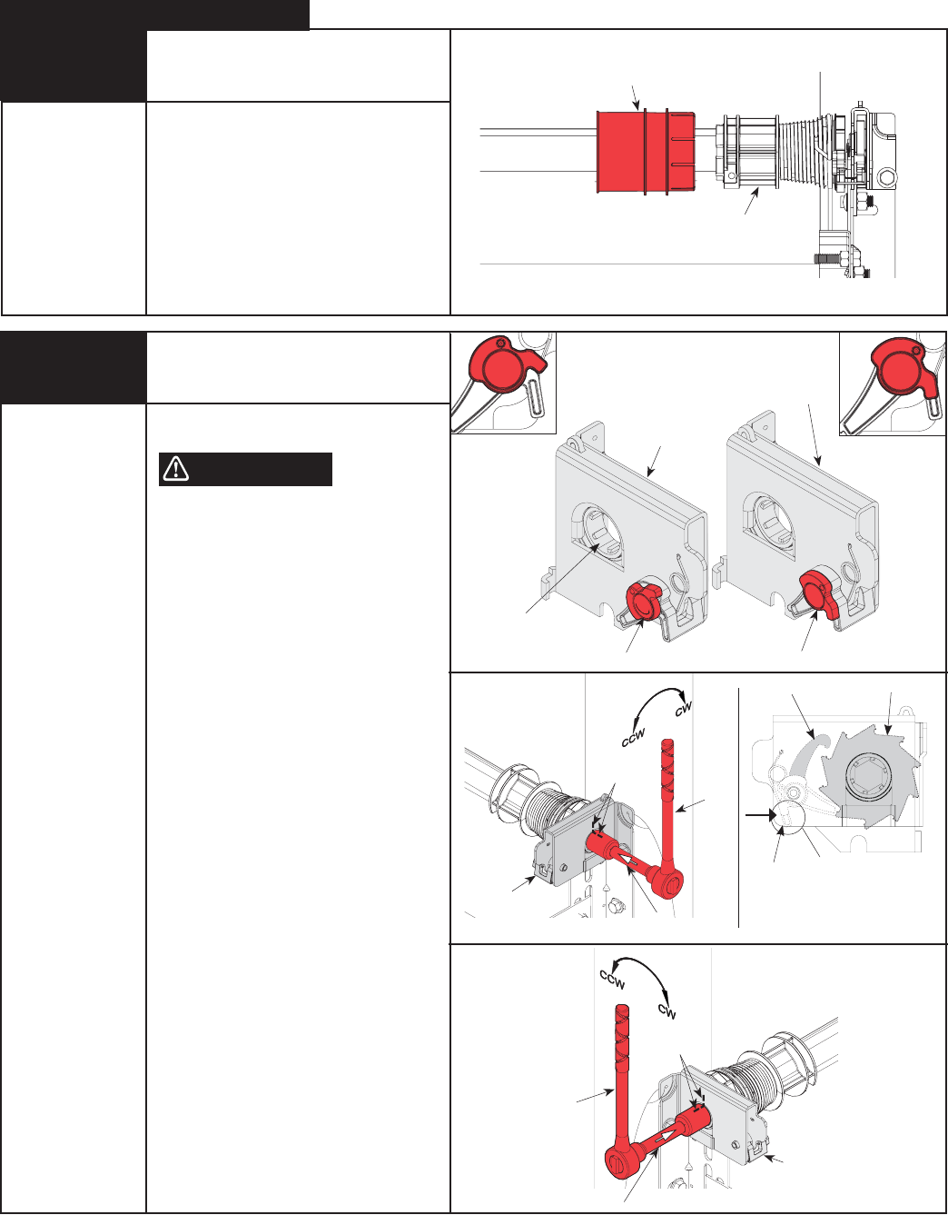
R2 Spring Tension Removal
Counterbalance spring tension must be
relieved before removing any hardware.
A POWERFUL SPRING RELEASING ITS
ENERGY SUDDENLY CAN CAUSE SEVERE
INJURY.
Starting with the right hand side, ensure
pawl knob is in upper position. Place a
ratchet with a 5/8” socket on the winding
shaft.
NOTE: A 3” extension is also recommended
for added clearance from the horizontal
angle.
To remove spring tension, ensure the ratchet
and socket is set so that it will add tension
(counter clockwise) on the right hand side
and (clockwise) on the left hand side. Rotate
ratchet to relieve pressure between the pawl
and the ratchet wheel. Push in on the pawl
to allow the ratchet wheel teeth to pass by.
NOTE: In the event of a broken spring, it
might not be necessary to unwind spring(s).
IMPORTANT! BE PREPARED TO HOLD THE
FULL TENSION OF THE SPRING.
Gently let the ratchet rotate upward, while
watching the number of teeth on the ratchet
wheel pass by the pawl. Remove 3/10 of a
turn (watch the 3 teeth of the ratchet wheel
pass the pawl). Release the pawl to allow it
to engage with the ratchet wheel. Repeat
this process until all spring tension has been
removed from spring(s). Cables should be
loose and the torque tube should be free to
rotate in either direction.
IMPORTANT! SPRING(S) ARE FULLY
UNWOUND WHEN COUNTERBALANCE
CABLES HAVE NO TENSION.
IMPORTANT! DO NOT USE AN IMPACT GUN
TO UNWIND THE SPRINGS.
Tools Needed:
Ratchet Wrench
5/8” Socket
3” Extension
Gloves
Step Ladder
INSTALLATION NOTICE: If installing the idrive® opener on a door currently installed with Torquemaster® or Torquemaster®
Plus counterbalance system, start the installation with Step: R1 below (for Torquemaster® Plus) or Step: R1 on page 3 (for
Torquemaster®).
WARNING
Rachet Bracket is under
EXTREME SPRING
TENSION.
To avoid possible severe or
fatal injury, DO NOT remove
fasteners from ratchet bracket
until spring(s) are fully
wnwound.
To safely unwind spring(s)
read
and follow the directions in the
installation instructions/owners
manual.
DO NOT REMOVE THIS TAG.
Pawl Knob In Upper Position
END BRACKET
Pawl Knob In Lower Position
END BRACKET
R1 Retro-Fit Installation
Drum Wrap & End Bracket
Removal
IMPORTANT! RIGHT AND LEFT HAND IS
ALWAYS DETERMINED FROM INSIDE THE
BUILDING LOOKING OUT.
NOTE: Warning tag removed for illustration
clarity.
Starting on the right hand side, remove the
drum wraps from the cable drums (if installed),
twist the drum wrap while pulling it away from
the drum. Repeat drum wrap removal for left
side.
Tools Needed:
Step Ladder
Retro-Fit TorqueMaster® Plus
Drum Wrap
Drum
WARNING
Ratchet
RIGHT HAND SIDE
LEFT HAND SIDE
Marks
3” Extension
Pawl
Marks
3” Extension
Ratchet
TORQUEMASTER® PLUS END BRACKET
(Right hand shown, left hand bracket symmetrically opposite)
PAWL KNOB
IN UPPER POSITION
PAWL KNOB
IN LOWER POSITION
Pawl
Ratchet Wheel
PAWL
RATCHET PAWL RATCHET WHEEL
Pushing in on Pawl Causes
Ratchet Pawl to move away
from Ratchet Wheel, allowing
wheel teeth to pass by.