Wayne Dalton 0001715 TORQUE MASTER i-DRIVE PRO User Manual INSTALLATION GUIDE 3
Wayne Dalton Corporation TORQUE MASTER i-DRIVE PRO INSTALLATION GUIDE 3
Contents
- 1. INSTALLATION GUIDE 1
- 2. INSTALLATION GUIDE 2
- 3. INSTALLATION GUIDE 3
- 4. INSTALLATION GUIDE 4
INSTALLATION GUIDE 3

5015 B.U. Bowman Drive Buford, GA 30518 USA Voice: 770-831-8048 Fax: 770-831-8598
Certification Test Report
908.42 MHz Low Power Communication Device Transceiver
372 MHz Discrete Receiver
FCC ID: KJ8-0001715
IC: 3540A-0001715
FCC Rule Part: 15.249
IC Radio Standards Specification: RSS-210
ACS Report Number: 07-0186 - 15C
Manufacturer: Wayne-Dalton Corporation
Model: 3790-Z
Installation Guide
Section3
11
Please Do Not Return This Product To The Store. Call Us Directly! Our Trained Technicians Will Answer Your Questions and/or Ship Any Parts You May Need.
You can reach us Toll Free at 1-888-827-3667 for Consumer Assistance or online at www.wayne-dalton.com
Loose
Winding
Shaft
Cable
Drum
Left Hand Side
Single Spring Application
Groove
Flagangle
Torsion
Tube
NOTE: If you just installed the
Torquemaster® Plus counterbalance,
continue with Step 5 on page 13. If you
have the Torquemaster® counterbalance
system, complete Steps 2-4 on pages 11
and 12.
Shake the torque tube gently to extend the
winding shafts out about 5" on each side.
For single spring applications, there will be
no left hand spring in the torque tube.
Lift the torque tube and rest it on the top of
the flagangles. Orient torque tube so that
back of opener is flat against header/
mounting surface.
NOTE: Cable drums and torque tube are
cam shaped to fit together only one way.
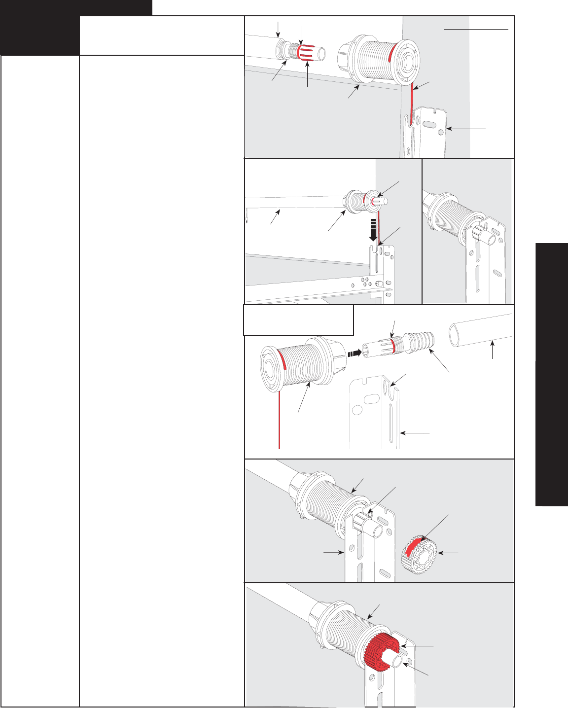
Pre-wrap the Torquemaster® cable drum
with the counter balance cable 1/2 wrap
(see illustrations).
To install the cable drum, slide the cable
drum over the winding shaft until the cable
drum seats against the torque tube. The
winding shaft must extend past the cable
drum far enough to expose the splines and
the groove.
Align the winding shaft groove with
the round notch in the flagangle.
Repeat for opposite side for double spring
applications.
For single spring applications, insert
the loose winding shaft into the left hand
cable drum prior to sliding the cable drum
over the torque tube.
NOTE: On single spring applications, take
care in handling the loose winding shaft
(left side) so that it does not slide back into
the torque tube.
Beginning with the right hand side, lubricate
entire circumference of the drive gear
with lubricating oil. Slide the drive gear onto
the winding shaft splines until it touches
the flagangle.
NOTE: On single spring applications,
no drive gear is required on the left side.
NOTE: If additional lubricating oil is
required “Dura-Lube Engine Oil Treatment”
is recommended.
Cable Drum/ Drive Gear
Installation
Torque
Tube
Winding
Shaft
Cable Drum
Counterbalance
Cable
Torque
Tube Cable Drum
Round
Notch
Winding
Shaft Groove
Winding
Shaft Splines
Lubricating
Oil
Drive
Gear
Flagangle
Drive
Gear
Winding
Shaft
Cable
Drum
Cable
Drum
Splines
Groove
Flag Angle
Round
Notch
2
TorqueMaster® Installation
Tools Needed:
Step Ladder
1/2 Wrap Shown
Winding
Shaft Groove
align and seated
in ro
IDRIVE
®
FOR TORQUEMASTER
®
INSTALLATION
12 Please Do Not Return This Product To The Store. Call Us Directly! Our Trained Technicians Will Answer Your Questions and/or Ship Any Parts You May Need.
You can reach us Toll Free at 1-888-827-3667 for Consumer Assistance or online at www.wayne-dalton.com
Tools Needed:
Step Ladder
End Bracket Installation
Counter Installation
IMPORTANT! WARNING TAGS MUST BE
SECURELY ATTACHED TO BOTH END
BRACKETS.
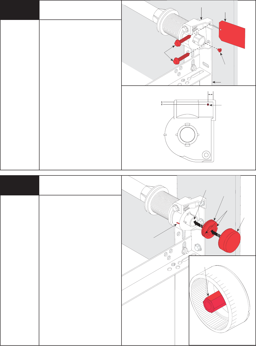
Slide the right hand end bracket over
the drive gear. Replace #10 phillips head
screw that was removed in Step R3. Secure
end bracket and the flagangle to the jamb
using (2) 5/16” x 1-5/8" lag screws.
NOTE: Older end brackets may not have
a hole needed for the opener’s emergency
disconnect cable. If the right hand end
bracket does not have a hole for the
disconnect cable, drill a 3/32" (3mm) hole
as shown prior to installing the end bracket.
Install the right side counter gear, with
the missing tooth toward the outside and
away from the end bracket. Press the
counter gear onto the end bracket until
snaps engage.
Select the right hand counter cover and
align the hex of the counter cam with
the end of the winding shaft. Also, align the
“0” on the counter cover with the raised rib
on the end bracket. Press the counter cover
against the counter gear until it locks into
place.
Repeat for left hand side for double
spring applications.
NOTE: No drive gear, counter gear or
counter cover is required on left hand side
for single spring applications. Only an end
bracket is needed.
IMPORTANT! AT THIS TIME DO NOT WIND
COUNTERBALANCE SPRINGS!
After completing this step, continue with
Step 5 on page 13.
Winding
Shaft Inside End
Bracket
Missing
Tooth
Raised Rib
Hex of the
Counter Cam
Counter
Cover
3/32” Hole
5/16 x 1-5/8”
Lag Screws
Counter
Gear
#10 Phillips
Head
Screw
Warning
Tag
1/4”
1/8”
Tools Needed:
Power Drill
3/32” Drill Bit
7/16”
Socket Driver
Phillips Head
Screwdriver
Step Ladder
End Bracket
Flagangle
3
4
13
Please Do Not Return This Product To The Store. Call Us Directly! Our Trained Technicians Will Answer Your Questions and/or Ship Any Parts You May Need.
You can reach us Toll Free at 1-888-827-3667 for Consumer Assistance or online at www.wayne-dalton.com
S1 S2 S3 S4
Learn Delete
Controls
S1 S2 S3 S4
Learn Delete
Controls
Positioning Support Bracket
NOTE: idrive® must be installed on a solid
mounting surface.
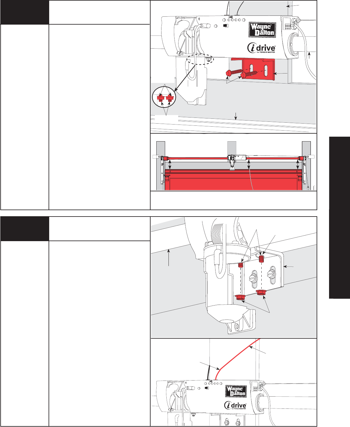
Locate the mounting surface. The mounting
surface is a vertical board running directly
above the center of the door. Remove
(2) 1/4”-20 flange nuts from bottom
of opener.
NOTE: Do not discard flange nuts.
Place the support bracket underneath
opener, to the right side of motor, centered
on mounting surface.
Using a tape measure, maintain equal
measurements between torque tube and top
of door at both ends and in center to ensure
torque tube is level. Once torque tube is
level, with idrive resting on support bracket,
drill 1/8” pilot holes for the lag screws.
Now secure support bracket to the mounting
surface with (2) 1/4” x 1-1/2" lag screws.
NOTE: If wood mounting surface is covered
with dry wall, use 1/4” x 2” lag screws.
1/4 x 1-1/2”
Lag Screws
Support
Bracket
1/4” - 20
Flange Nuts
Mounting
Studs
Mounting
Surface
(Header)
Top Of Door
Attaching Opener To
Support Bracket
Lift and slide the opener over the support
bracket, aligning the mounting studs with
the bracket slots. Loosely fasten to
mounting studs with the (2) 1/4”-20
flange nuts.
Alternately, the disconnect cable can be
pulled to allow motor to pivot up. This will
enable assembly of the support bracket to
the opener first, followed by leveling of the
torque tube and then attachment of support
bracket to mounting surface.
NOTE: Do not tighten 1/4”-20 flange
nuts to opener studs at this time.
Remove the orange label holding the
antenna wire. Straighten antenna wire and
angle it 45 degrees to the right.
NOTE: Do not coil the antenna wire. This
will reduce the radio signal range.
Antenna Wire
(2) 1/4”-20
Flange Nuts
Support
Bracket
Mounting
Studs
45° Angle
Tools Needed:
Step Ladder
Bracket
Slots
Torque Tube
Torque Tube
USING A TAPE MEASURE, MAINTAIN AN EQUAL MEASUREMENT “X” (TOP OF DOOR
TO BOTTOM OF TORQUEMASTER® TUBE) AT BOTH ENDS AND THE CENTER.
TOP SECTION
“X” “X” “X”
Tools Needed:
Power Drill
1/8” Drill Bit
7/16” Socket
Driver
Tape Measure
Step Ladder
5
6
IDRIVE
®
FOR TORQUEMASTER
®
INSTALLATION
14 Please Do Not Return This Product To The Store. Call Us Directly! Our Trained Technicians Will Answer Your Questions and/or Ship Any Parts You May Need.
You can reach us Toll Free at 1-888-827-3667 for Consumer Assistance or online at www.wayne-dalton.com
S1S2S3S4
LearnDelete
Controls
S1S2S3S4
LearnD
elete
Controls
Attaching Disconnect Cable
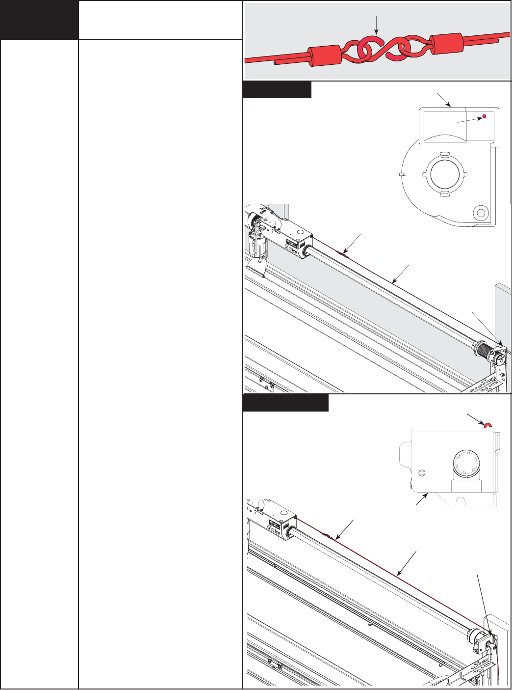
Attach the loose disconnect cable (located in
opener hardware bag) to the opener with the
“S” hook. Close both ends of the “S” hook
with pliers, to lock assembly together with
pliers.
Thread the disconnect cable (behind the
counterbalance cable) through the hole in
the right hand end bracket, and remove all
slack between opener and right end
bracket.
Close “S” Hook
Disconnect
Cable
S-Hook
Hole in Right
End Bracket
Hole in
End Bracket
Right Side of
End Bracket
Disconnect
Cable
S-Hook
Hole in Right
End Bracket
Hole in
End Bracket
Right Side of End
Bracket
7
Tools Needed:
Power Drill
1/8” Drill Bit
7/16” Socket
Driver
Tape Measure
Step Ladder
Torquemaster®
Torquemaster® Plus
15
Please Do Not Return This Product To The Store. Call Us Directly! Our Trained Technicians Will Answer Your Questions and/or Ship Any Parts You May Need.
You can reach us Toll Free at 1-888-827-3667 for Consumer Assistance or online at www.wayne-dalton.com
6ft
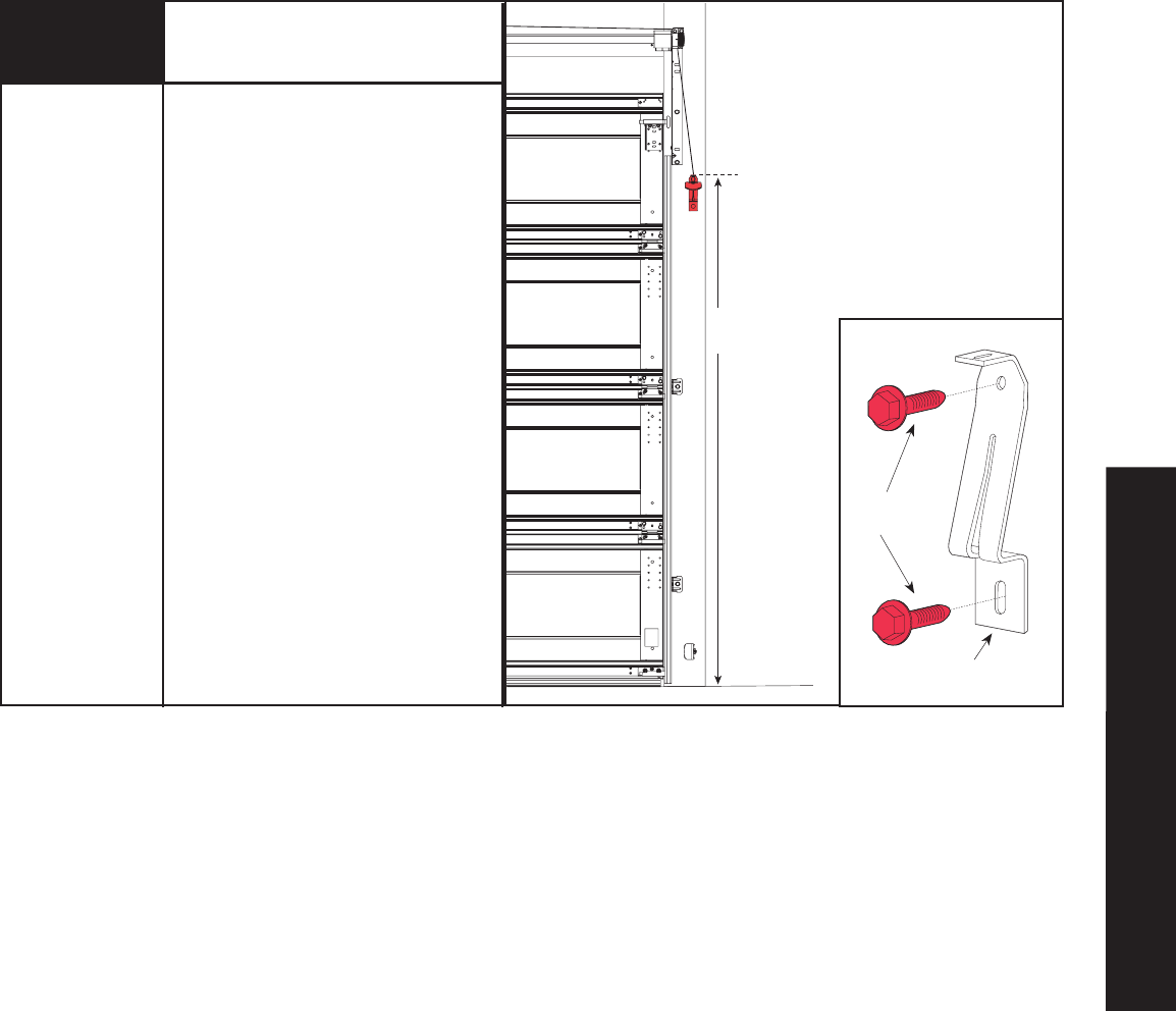
Mounting Disconnect
Handle Bracket
Mark a location on the right jamb, 6 feet
above the floor to mount the disconnect
handle bracket.
Pilot drill lag screw location using
1/8" drill bit.
Align top of the bracket with the mark.
Fasten bracket to the jamb with
(2) 1/4” x 1-1/2" lag screws.
1/4” x 1-1/2”
Lag Screws
Disconnect
Handle Bracket
Tools Needed:
Pencil
Tape Measure
Power Drill
1/8" Drill Bit
7/16” Socket
Driver
8
IDRIVE
®
FOR TORQUEMASTER
®
INSTALLATION
16 Please Do Not Return This Product To The Store. Call Us Directly! Our Trained Technicians Will Answer Your Questions and/or Ship Any Parts You May Need.
You can reach us Toll Free at 1-888-827-3667 for Consumer Assistance or online at www.wayne-dalton.com
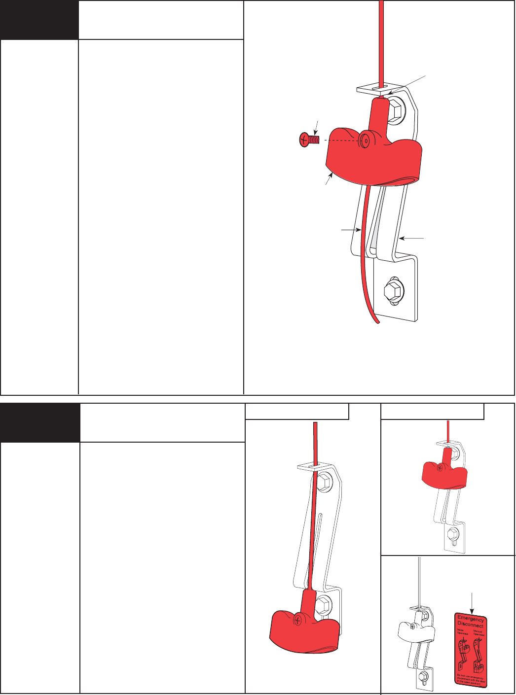
Attaching Disconnect Handle
#6-20 x 1/2”
Screw
Disconnect
Handle
Bracket
Disconnect
Cable
Disconnect
Handle
Upper
Position
Apply emergency disconnect label next to
the mounted bracket. Use mechanical
fasteners if adhesive will not adhere.
Using the emergency disconnect, pull down
on disconnect handle and place it in the
manual door operated position (use
disconnect label for reference). Motor will
be rotated 90° from its packaged position.
If motor does not pivot 90°, see
troubleshooting section in this manual.
Disconnect Handle Usage
Emergency
Disconnect
Label
Manual operated position Motor operated position
Tools Needed:
None
Tools Needed:
Phillips
Head
Screwdriver
Wire Cutters
Flat Blade
Screwdriver
NOTE: The motor must be in the fully down
position before setting handle position on
cable. Bring motor to the down position by
pulling the disconnect cable while pushing
the motor down. Insure opener disconnect
teeth are engaged before installing
disconnect handle. If motor is not fully
down when teeth are engaged, turn motor
shaft with screwdriver at back of motor
counter clockwise until motor is fully down.
NOTE: Do not use power drill to assemble
set screw to handle.
Start the #6-20 x 1/2" screw into the
disconnect handle. Thread the disconnect
cable through the top of the disconnect
handle bracket and then the disconnect
handle.
Locate the disconnect handle in full upper
position of disconnect handle bracket.
Remove all disconnect cable slack between
the opener and the top of the disconnect
handle bracket. Tighten #6-20 x 1/2"
screw into the disconnect handle until
snug, and then tighten screw an additional
1 to 1-1/2 turns to secure disconnect cable
to the disconnect handle. Trim off excess
cable from bottom of the disconnect
handle.
CAUTION: PULL CABLE ONLY TAUT
ENOUGH TO REMOVE THE CABLE SLACK.
PULLING THE CABLE MORE COULD CAUSE
OPENER TO DISCONNECT FROM THE
TORQUE TUBE AND CAUSE FAILURE OF
THE DISCONNECT.
9
10
17
Please Do Not Return This Product To The Store. Call Us Directly! Our Trained Technicians Will Answer Your Questions and/or Ship Any Parts You May Need.
You can reach us Toll Free at 1-888-827-3667 for Consumer Assistance or online at www.wayne-dalton.com
Cable Adjustments
Tools Needed:
Pliers/Wire
Cutter
Flat Tip
Screwdriver
Step Ladder
Cam Peak
Straight Up
11 Torquemaster®
Torquemaster® Plus
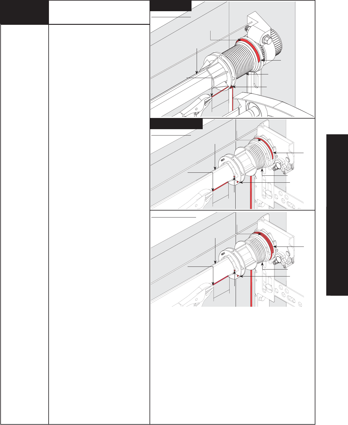
Counterbalance Cable
Starting on the right hand side, rotate the
cable drum until the set screw faces
directly away from the header. Torque tube
cam peak should be pointing straight up.
NOTE: Illustrations show the right hand
cable drum, left hand cable drum is
symmetrically opposite.
NOTE: Cable tension is set during the initial
door installation. If there is slack between
the counterbalance cable and the cable
drum or unequal tension between the right
and left hand counterbalance cables, the
counterbalance cables will have to be
readjusted. If there is no slack and cable
tension is equal, proceed to Step 12.
Loosen the set screw no more than 1/2
turn. Using locking pliers, pull on the end of
the cable to remove all cable slack.
IMPORTANT! A MINIMUM OF A 1/2 WRAP
IS REQUIRED FOR PROPER DOOR
OPERATION. CABLE MUST BE TAUT AND IN
THE SPIRAL, OR THREAD, OF THE CABLE
DRUM.
Check to ensure the cable is aligned and
seated in the first groove of the cable drum.
Snug the set screw, and then tighten an
additional 1-1/2 turns. Left side will be
adjusted in Step 13.
IMPORTANT! ENSURE THE CABLE IS
ALIGNED AND SEATED IN THE FIRST
GROOVE OF THE CABLE DRUM PRIOR TO
WINDING SPRINGS.
Measure approximately 6” of cable, cut off
excess cable, tuck end into cable drum
(Torquemaster®) or insert end in hole of
cable drum (Torquemaster® Plus).
First Groove
Right Hand Drum
Cut Cable Here
Set Screw
1/2 Wrap Shown
6”
1/2 Wrap Shown
1-1/2 Wrap Shown
6”
6”
Cut Cable Here
Cam Peak
Straight Up
Counterbalance Cable
First Groove
Right Hand Drum
Set Screw
Hole
Cut Cable Here
Cam Peak
Straight Up
Counterbalance Cable
First Groove
Right Hand Drum
Set Screw
Hole
IDRIVE
®
FOR TORQUEMASTER
®
INSTALLATION
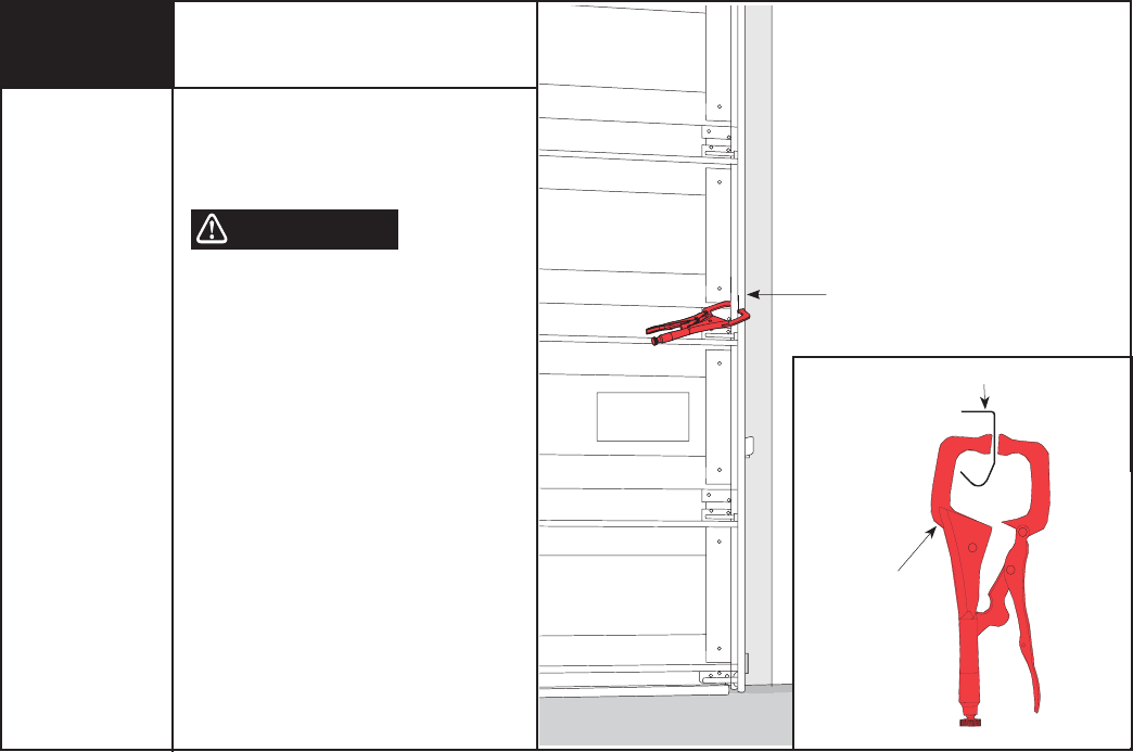
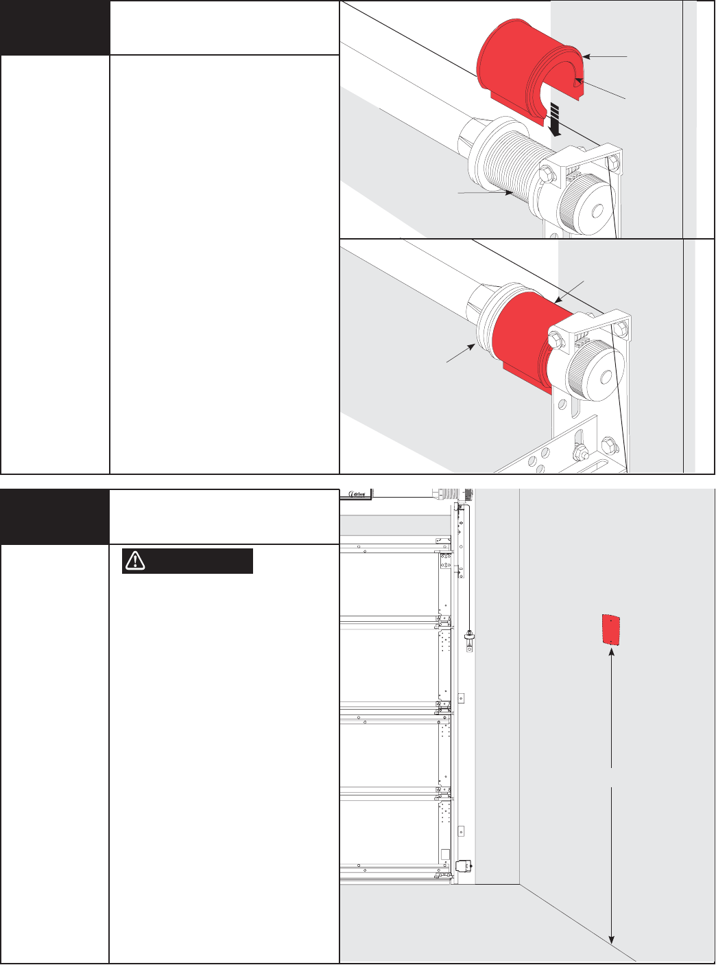
Place vice clamps onto both vertical tracks
just above the third roller. This is to prevent
the garage door from raising while winding
the springs.
FAILURE TO CLAMP TRACK CAN ALLOW
DOOR TO RAISE UNEXPECTEDLY,
RESULTING IN SEVERE OR FATAL
INJURY.
IMPORTANT! DO NOT USE IMPACT GUN
TO WIND SPRING(S)
Securing Door
for Spring Winding
Tools Needed:
Vice Clamps
WARNING
TRACK
VICE CLAMPS ATTACHED
TO INNER
RAIL OF TRACK
PLACE VICE CLAMPS
ABOVE 3RD ROLLER
12
18
Please Do Not Return This Product To The Store. Call Us Directly! Our Trained Technicians Will Answer Your Questions and/or Ship Any Parts You May Need.
You can reach us Toll Free at 1-888-827-3667 for Consumer Assistance or online at www.wayne-dalton.com
19
Please Do Not Return This Product To The Store. Call Us Directly! Our Trained Technicians Will Answer Your Questions and/or Ship Any Parts You May Need.
You can reach us Toll Free at 1-888-827-3667 for Consumer Assistance or online at www.wayne-dalton.com
Cable Drum
No space between Ratchet
Pawl and Cable Drum
indicates engagement
Cable Drum
Ratchet Pawl
ENGAGED SIDE VIEW
No space between
Ratchet Pawl and
Cable Drum
ENGAGED UNDERNEATH VIEW
Space between Ratchet Pawl
and Cable Dru
m
non-indica
tes
Cable Dru
m
Ratchet Pawl
DISENGAGED SIDE VIEW
No space between
Ratchet Pawl and
DISENGAGED UNDERNEATH VIEW
UPPER POSITION
Use these Illustration, in conjunction with the Instructions on the other side
this label.
WARNING
WARNING
Rachet Bracket is under
Rachet Bracket is under
EXTREME SPRING
EXTREME SPRING
TENSION
TENSION.
To avoid possible severe or
To avoid possible severe or
fatal injury,
fatal injury,
DO NOT
DO NOT
remove
remove
fasteners from ratchet bracket
fasteners from ratchet bracket
until spring(s) are fully
until spring(s) are fully
wnwound.
wnwound.
To safely unwind spring(s)
To safely unwind spring(s)
read
read
and follow the directions in the
and follow the directions in the
installation instructions/owners
installation instructions/owners
manual.
manual.
DO NOT REMOVE THIS TAG .
DO NOT REMOVE THIS TAG.
NOTE: If you have a Torquemaster®
counterbalance, skip this step and continue
with Step 13 on page 21.
NOTE: It is recommended that leather
gloves be worn while winding the
TorqueMaster® Plus springs.
FAILURE TO WEAR GLOVES MAY CAUSE
INJURY TO HANDS.
See chart on page 20 for proper spring
tension setting.
Double check to ensure the counterbalance
cable is aligned in the first groove of the
cable drum, as shown in Step 11.
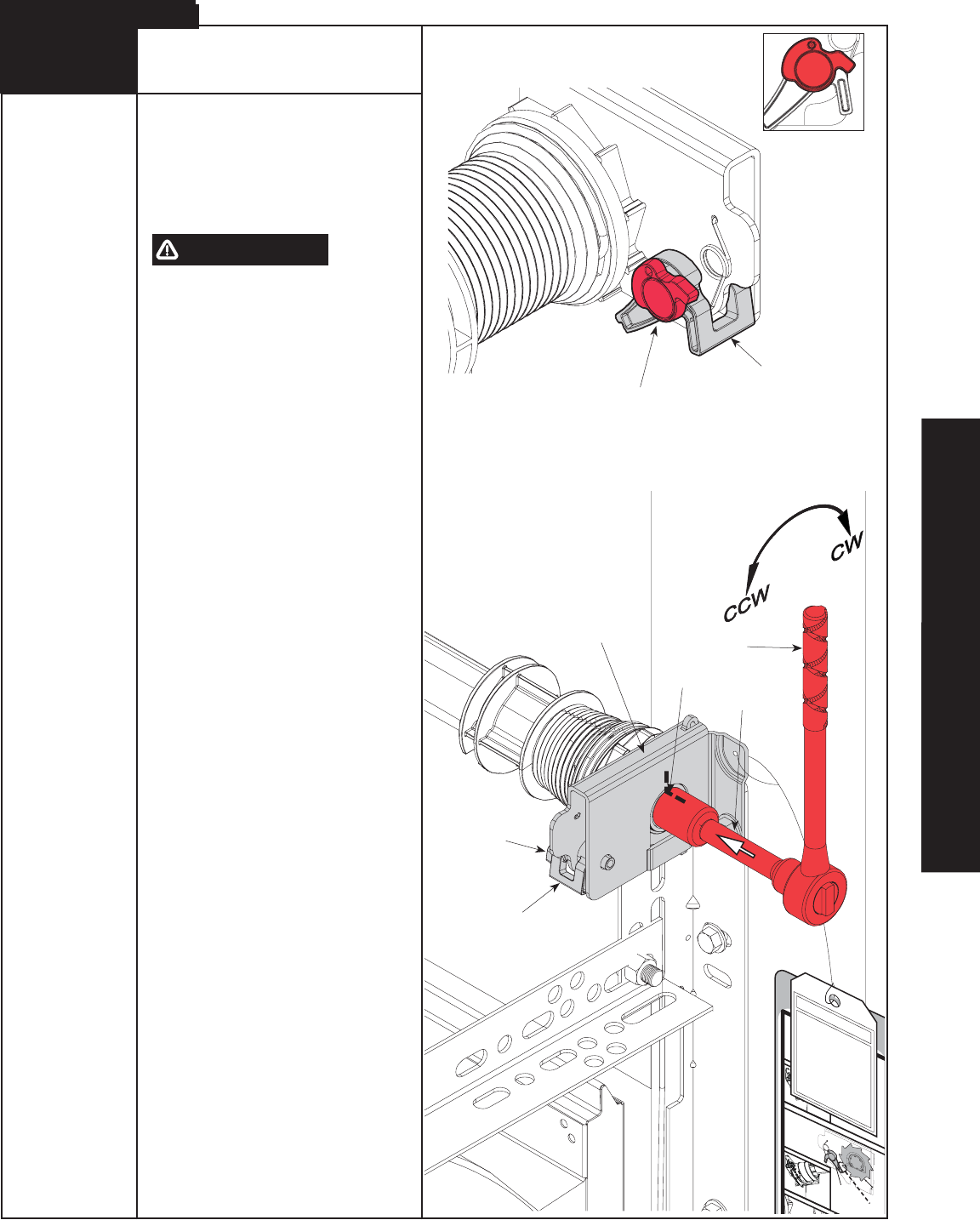
IMPORTANT! PAWL KNOB MUST BE IN
UPPER POSITION TO ADD/ REMOVE SPRING
TURNS. AFTER ADDING / REMOVING SPRING
TURNS, PAWL KNOB MUST BE PLACED
BACK IN LOWER POSITION.
Beginning with the right side, place a mark
on winding shaft (or socket) and end bracket.
Turn pawl knob on the end bracket to the
upper position. Using a ratchet with a 5/8”
socket,wind the spring by rotating the
winding shaft counter clockwise, while
watching the mark on the winding shaft.
NOTE: A 3” extension is also recommended
for added clearance from the horizontal
angle.
After 2-3 turns, remove the ratchet and
adjust the cable on the left side. Ensure the
cable is in the first groove of the cable
drums as shown in Step 11 and clear of any
obstructions.
NOTE: Single spring applications require no
spring winding on left hand side, but need
cable tension adjusted.
IMPORTANT! ENSURE COUNTERBALANCE
CABLE TENSION IS EQUAL FOR BOTH SIDES
PRIOR TO FULLY WINDING SPRING(S) TO
APPROPRIATE NUMBER OF TURNS. IF
CABLE TENSION IS UNEQUAL, REFER TO
STEP 11.
See the Spring Turn chart.
For SINGLE SPRING applications, return to
the right hand side and continue winding the
spring to the required number of turns for
your door or the number record during the
Pre-Installation Inspection on page II. Place
pawl knob in lower position.
For DOUBLE SPRING applications, place a
mark on the left hand winding shaft and end
bracket. Place the ratchet with 5/8” socket
onto the left hand winding shaft end.
Winding Spring(s)
Tools Needed:
5/8” Socket
Ratchet Wrench
3” Extension
Step Ladder
WARNING
Mark
Pawl Knob In Upper Position
Ratchet
3” Extension
Pawl Knob
End Bracket
13
TorqueMaster® Plus
PAWL KNOB
IN UPPER POSITION
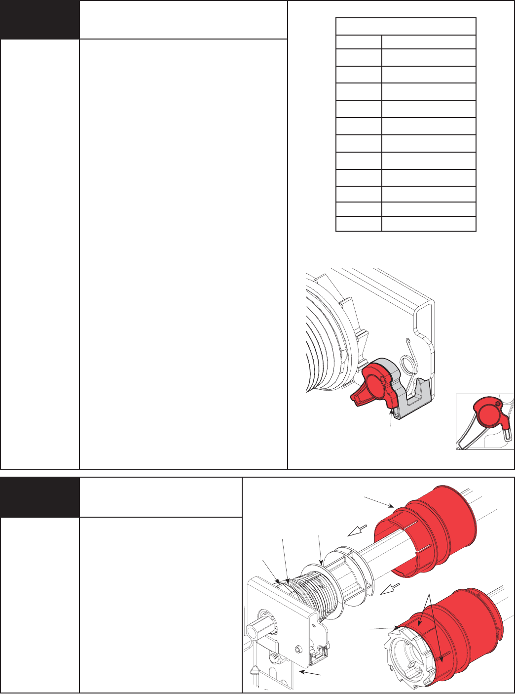
Pawl
Pawl
IDRIVE
®
FOR TORQUEMASTER
®
INSTALLATION
To wind the spring, rotate the winding shaft clockwise,
while watching the mark on the winding shaft (or
socket). Rotate the winding shaft to the required number
of turns for your door or the number recorded during the
Pre-Installation Inspection on page II. Place ratchet pawl
in lower position. Then return to the right hand side and
wind the right hand spring to the required number of
turns or the number recorded during the Pre-Installation
Inspection on page II. Place ratchet pawl in lower
position.
IMPORTANT! DO NOT OVERWIND SPRINGS.
NOTE: Since total turns to balance door can deviate
from spring turn chart values by ± 1/2 turns,
adjustments to the recommended number of spring
turns may be required AFTER rear hangers assembly is
completed.
IMPORTANT! HOLD THE DOOR DOWN TO PREVENT IT
FROM RAISING UNEXPECTEDLY IN THE EVENT THE
SPRING WAS OVERWOUND AND CAUTIOUSLY REMOVE
VICE CLAMPS FROM VERTICAL TRACKS.
IMPORTANT! ADJUSTMENTS TO THE RECOMMENDED
NUMBER OF TURNS MAY BE REQUIRED. IF DOOR
RAISES OFF THE FLOOR UNDER SPRING TENSION
ALONE, THEN REDUCE SPRING TENSION UNTIL DOOR
RESTS ON THE FLOOR. IF THE DOOR IS HARD TO RAISE
OR DRIFTS DOWN ON ITS OWN, THEN ADD SPRING
TENSION. AN UNBALANCED DOOR CAN CAUSE IDRIVE®
OPERATION PROBLEMS.
IMPORTANT! IF YOU ARE INSTALLING THE IDRIVE®
OPENER ON A NEW GARAGE DOOR, REAR SUPPORTS
WILL NEED TO BE FABRICATED/ INSTALLED TO
SUPPORT THE HORIZONTAL TRACKS. REAR SUPPORTS
ARE CONSTRUCTED USING PERFORATED ANGLES, HEX
HEAD BOLTS/NUTS AND THEN THE MUST BE SECURELY
ATTACHED TO SOUND FRAMING MEMBERS WITH LAG
SCREWS. FOR DETAILED INFORMATION ON
CONSTRUCTING/ SUPPORTING THE REAR SUPPORTS,
REFER TO YOUR DOORS INSTALLATION INSTRUCTIONS
AND OWNER’S MANUAL.
Winding Spring(s)
(Continued)
Pawl Knob In Lower Position
Drum Wrap
(Left Hand)
Drum
(Left Hand)
Groove
In Drum
Tabs
Tools Needed:
Tools Needed:
Step Ladder
To install drum wraps, position the left hand
drum wrap over the left hand drum, align
with counterbalance cable; slide groove in
drum wrap towards the left until tabs snap
over drum in between drum and Drum
gear. Repeat for right hand side.
IMPORTANT: Right and left hand are always
determined from inside the building looking
out.
After completing this Step, continue with
Step 15 on page 22.
Drum Wrap Installation
Counterbalance Cable
14
RECOMMENDED SPRING TURNS
Door Height Spring Turns
6’-0” 14
6’-3” 14-1/2
6’-5” 15
6’-6” 15
6’-8” 15-1/2
6’-9” 15-1/2
7’-0” 16
7’-3” 16-1/2
7’-6” 17
7’-9” 17-1/2
8’-0” 18
PAWL KNOB
IN LOWER POSITION
20 Please Do Not Return This Product To The Store. Call Us Directly! Our Trained Technicians Will Answer Your Questions and/or Ship Any Parts You May Need.
You can reach us Toll Free at 1-888-827-3667 for Consumer Assistance or online at www.wayne-dalton.com
Drum Gear
Groove in
Drum
Setting Spring Tension
See chart below for proper spring tension setting.
Beginning with the right hand side, ensure the
counterbalance cable is in the first groove of the cable
drum. NOTE: Apply light pressure to the canoe clip on
counter while winding springs.
Using a power drill (high torque/gear reduced to 1300
RPM preferred) with a 7/16" socket driver, carefully rotate
right hand winding bolt clockwise, until counter shows 2-3
turns. This will keep the counterbalance cable taut while
adjusting the left hand side counterbalance cable.
Adjust left hand counterbalance cable tension (Refer to
step 11).
NOTE: Single spring applications require no spring winding
on left hand side, but need cable tension adjusted.
IMPORTANT! Ensure counterbalance cable tension is
equal for both sides prior to fully winding spring(s) to
appropriate number of turns. If cable tension is unequal,
refer to Step 11.
See the Spring Turn chart.
For SINGLE SPRING applications, return to the right
hand side and carefully rotate the winding bolt head
clockwise until the counter shows the correct number of
turns for your door or the number record during the
Pre-Installation Inspection on page II.
For DOUBLE SPRING applications, remain on the left
hand side and carefully rotate the winding bolt head
clockwise until the counter shows the correct number of
turns for your door or the number record during the Pre-
Installation Inspection on page II. Then return to the right
hand side and wind the right hand spring to the required
number of turns for your door or the number recorded
during the Pre-Installation inspection on page II.
IMPORTANT! DO NOT OVERWIND.
After spring is wound, hold the lock nut (in back of end
bracket) stationary with a 7/16" wrench while rotating the
winding bolt clockwise until snug. Tightening of the lock
nut prevents spring from unwinding. Repeat for opposite
side on double spring Torquemaster® systems.
IMPORTANT! CAUTIOUSLY REMOVE VICE CLAMPS
FROM VERTICAL TRACKS. ADJUSTMENTS TO THE
RECOMMENDED NUMBER OF TURNS MAY BE REQUIRED.
IF DOOR RAISES OFF THE FLOOR UNDER SPRING
TENSION ALONE, THEN REDUCE SPRING TENSION UNTIL
DOOR RESTS ON THE FLOOR. IF THE DOOR IS HARD TO
RAISE OR DRIFTS DOWN ON ITS OWN, THEN ADD SPRING
TENSION. AN UNBALANCED DOOR CAN CAUSE IDRIVE®
OPERATION PROBLEMS.
IMPORTANT! IF YOU ARE INSTALLING THE IDRIVE®
OPENER ON A NEW GARAGE DOOR, REAR SUPPORTS
WILL NEED TO BE FABRICATED/ INSTALLED TO
SUPPORT THE HORIZONTAL TRACKS. REAR SUPPORTS
ARE CONSTRUCTED USING PERFORATED ANGLES, HEX
HEAD BOLTS/NUTS AND THEN THE MUST BE SECURELY
ATTACHED TO SOUND FRAMING MEMBERS WITH LAG
SCREWS. FOR DETAILED INFORMATION ON
CONSTRUCTING/ SUPPORTING THE REAR SUPPORTS,
REFER TO YOUR DOORS INSTALLATION INSTRUCTIONS
AND OWNER’S MANUAL.
RECOMMENDED SPRING TURNS
Door Height Doors 11’-11”
Wide or Less
Doors 12’ Wide or
Greater
6’-0” 13-1/2 14
6’-3” 14 14-1/2
6’-5” 14-1/2 15
6’-6” 14-1/2 15
6’-8” 15 15-1/2
6’-9” 15 15-1/2
7’-0” 15-1/2 16
7’-3” 16 16-1/2
7’-6” 16-1/2 17
7’-9” 17 17-1/2
8’-0” 17-1/2 18
NOTE: For 7’ high doors, 8’, 9’, 10’, 16’ or 18’
wide with windows, the recommended number of
spring turns is 15.
Tools Needed:
Power Drill
7/16" Socket
Driver
7/16" Wrench
Step Ladder
Canoe Clip
Winding
Bolt
Power
Drill
7/16”
Socket
Driver
15.5
Counter
(Sample Setting)
Winding
Bolt
Canoe Clip
13
TorqueMaster®
7/16”
Wrench
Lock Nut
IDRIVE
®
FOR TORQUEMASTER
®
INSTALLATION
21
Please Do Not Return This Product To The Store. Call Us Directly! Our Trained Technicians Will Answer Your Questions and/or Ship Any Parts You May Need.
You can reach us Toll Free at 1-888-827-3667 for Consumer Assistance or online at www.wayne-dalton.com
22 Please Do Not Return This Product To The Store. Call Us Directly! Our Trained Technicians Will Answer Your Questions and/or Ship Any Parts You May Need.
You can reach us Toll Free at 1-888-827-3667 for Consumer Assistance or online at www.wayne-dalton.com
TO PREVENT POSSIBLE INJURY, INSTALL
WALL STATION OUT OF THE REACH OF
CHILDREN AND IN A LOCATION WHERE
THE DOOR CAN BE SEEN WHEN THE
OPENER IS ACTIVATED. DO NOT MOUNT
WALL STATION NEAR OR NEXT TO
GARAGE DOOR.
NOTE: For proper operation, mount the wall
station on a flat surface.
The wall station can be mounted to a NEMA
standard electrical device box or directly to
any wall surface. No wiring is required.
Select appropriate place to mount wall
station. To keep wall station out of the reach
of children, locate it at least five feet up
from the floor.
Mounting Wall Station
5’ Min
Tools Needed:
Tape Measure
WARNING
15
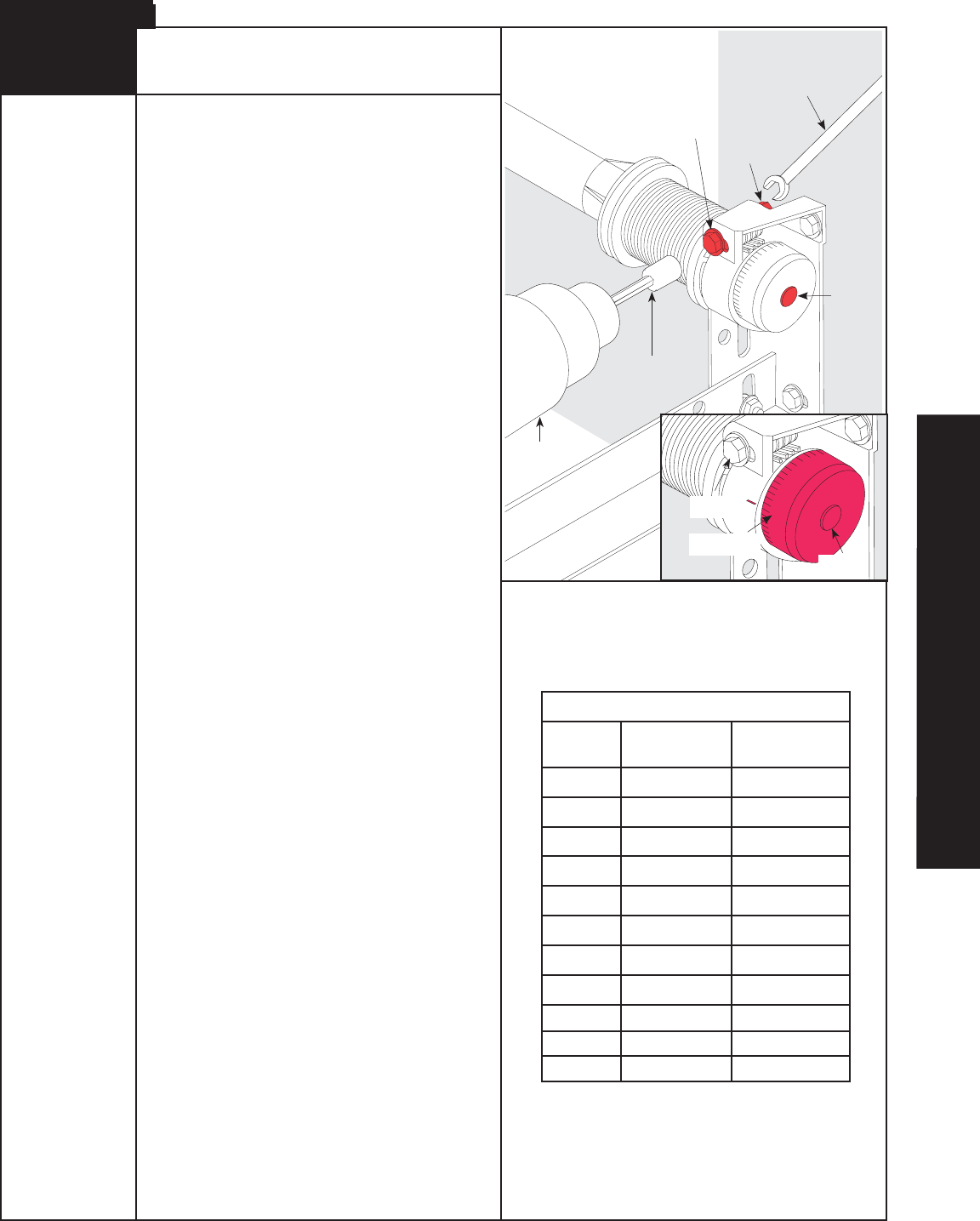
Drum Wrap Installation
Drum wraps (supplied with Torquemaster®
counterbalance systems) are identified as
right and left.
To install, place the drum wrap over the
cable drum and under the idrive® disconnect
cable. Align the outside flange over the
outside edge of the cable drum
and push the drum wrap down onto the
cable drum.
Drum
Wrap
Cable
Drum
Drum
Wrap
Cable
Drum
Tools Needed:
Step Ladder Outside
Flange
14
23
Please Do Not Return This Product To The Store. Call Us Directly! Our Trained Technicians Will Answer Your Questions and/or Ship Any Parts You May Need.
You can reach us Toll Free at 1-888-827-3667 for Consumer Assistance or online at www.wayne-dalton.com
Mounting Wall Station
(Continued)
Installing Battery
Press
Here
T
o
O
p
e
r
a
t
e
D
o
o
r
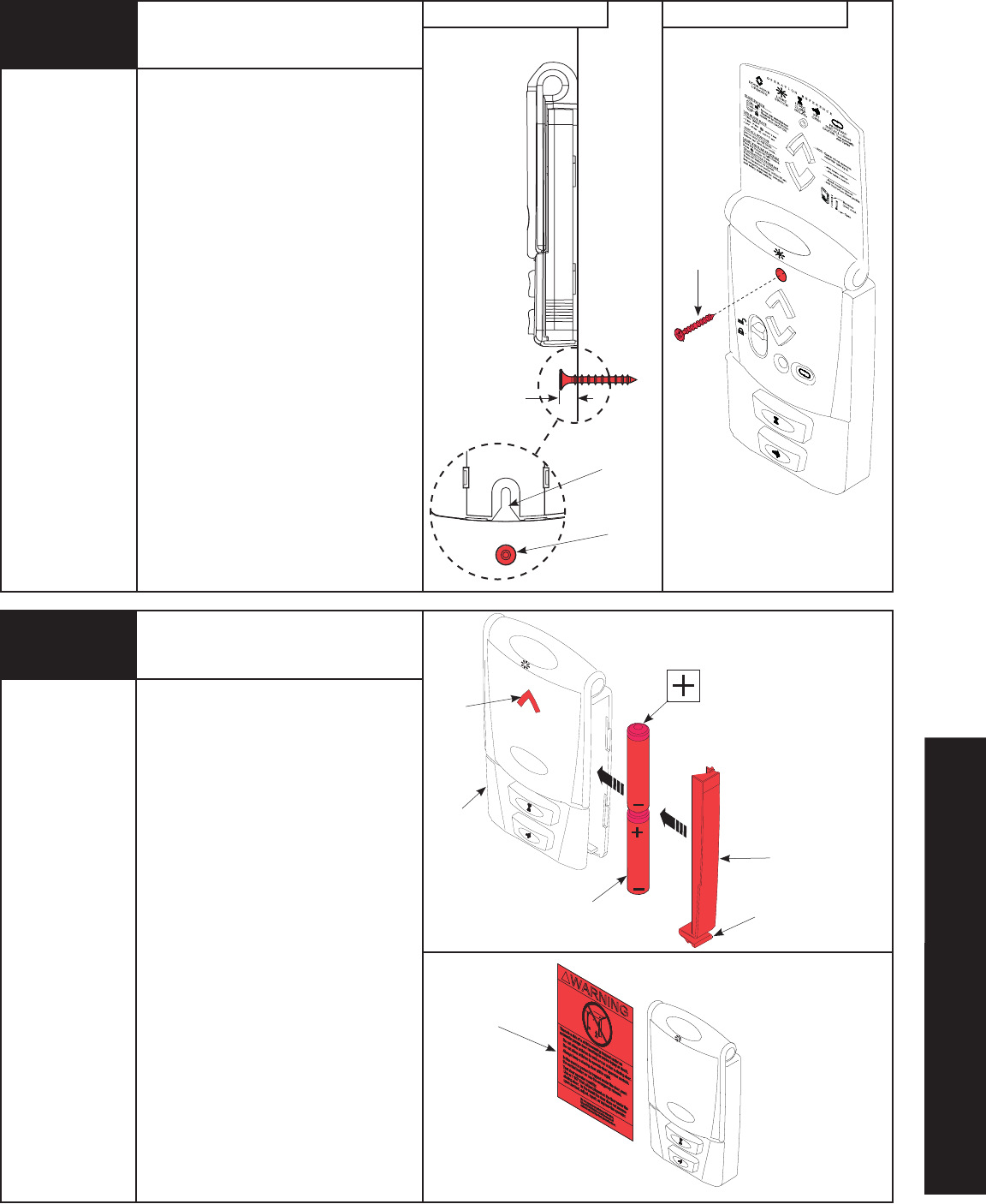
Lower Screw Installation Upper Screw Installation
T
o
O
p
e
r
a
t
e
D
o
o
r
Press
Here
Battery
Cover
Entrapment
Label
Keyhole
Slot
Phillips
Head Screw
Phillips
Head Screw
Wall
Station
(2) AAA
Batteries
Lower
Clip
Tools Needed:
Power Drill
3/16” or
3/32" Drill Bit
Phillips Head
Screwdriver
Tools Needed:
None
16
LED
Remove the battery cover (right-hand side
of wall station) by disengaging the battery
cover’s lower clip.
Install two AAA batteries into the wall
station observing the polarity, (+) and (-),
of both batteries. After about three seconds,
the red LED will begin to blink momentarily
every three seconds.
Re-install the battery cover by first inserting
its top into the wall station then inserting
and securing its bottom.
Apply entrapment warning label in a
convenient location next to the wall station.
Use mechanical fasteners if adhesive will
not adhere.
NOTE: To slow blink rate or turn off the red
LED, refer to wall station operation page 35
“Backlit LED Light”.
7/16”
If mounting to a NEMA electrical device box,
use machine thread screws provided in
place of the wood screws. No drilling is
required. If high voltage wiring is contained
in the box, a standard NEMA solid faceplate
must be installed between the box and the
wall station. If fastening into drywall or
concrete, use anchors provided. When
mounting to wood use a 3/32" drill bit and
the drilling template located on page 46.
Drill the two 3/32” mounting holes using the
drill template. Drill 3/16" holes if using
anchors.
Install lower screw leaving 7/16" of the
screw exposed. Slide wall station keyhole
slot onto the lower phillips head screw. Wall
station should slide onto screw, providing a
snug fit. If necessary remove wall station
and loosen or tighten lower phillips head
screw until a snug fit is achieved.
Once wall station is fitted on lower screw,
install upper screw. Do not over-tighten.
CAUTION: Over-tightening the upper screw
could deform plastic case.
PRE-OPERATION
24 Please Do Not Return This Product To The Store. Call Us Directly! Our Trained Technicians Will Answer Your Questions and/or Ship Any Parts You May Need.
You can reach us Toll Free at 1-888-827-3667 for Consumer Assistance or online at www.wayne-dalton.com
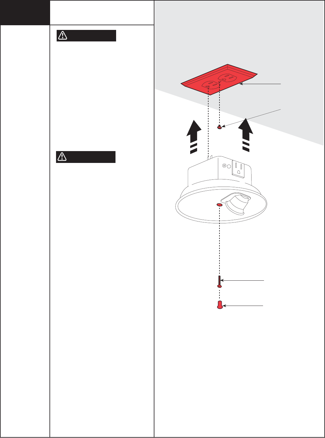
Receptacle Cover
#6-32 x 3/4”
Phillips Pan Head
Screw
Hole Plug
Remove Screw
Installing the Light Fixture
TO AVOID ELECTRICAL SHOCK
DISCONNECT POWER TO THE
RECEPTACLE AT THE FUSE/BREAKER
BOX, BEFORE PROCEEDING WITH THE
INSTALLATION OF THE LIGHT FIXTURE.
IMPORTANT! THIS LIGHT FIXTURE HAS A
GROUNDING TYPE PLUG WITH A THIRD
(GROUNDING) PIN. THIS PLUG WILL ONLY
FIT INTO A GROUNDING-TYPE OUTLET. IF
THE PLUG DOES NOT FIT INTO YOUR
OUTLET, CONTACT A QUALIFIED
ELECTRICIAN TO INSTALL THE PROPER
GROUNDING TYPE OUTLET. DO NOT ALTER
THE PLUG IN ANY WAY.
TO AVOID ELECTRICAL SHOCK/FIRE, DO
NOT MOUNT THE LIGHT FIXTURE TO A
RECEPTACLE WITH A METAL FACE
PLATE.
IMPORTANT! GARAGE DOOR MUST
CLEAR LIGHT FIXTURE WHEN THE DOOR IS
IN THE OPEN POSITION.
The light fixture is designed to mount
directly to a standard 120V duplex
receptacle.
Remove the screw in the receptacle
cover. Holding receptacle cover in place,
insert light fixture into the receptacle that
has the ground hole farthest from screw
hole.
Secure light fixture to receptacle with a
#6-32 x 3/4” phillips pan head screw.
Install hole plug into the screw hole in the
light fixture.
NOTE: For temperature protection, the
hole plug must be in place prior to using
the light fixture.
WARNING
WARNING
17
Tools Needed:
Phillips Head
Screwdriver
Flat Tip
Screwdriver
Step Ladder
FPO
25
Please Do Not Return This Product To The Store. Call Us Directly! Our Trained Technicians Will Answer Your Questions and/or Ship Any Parts You May Need.
You can reach us Toll Free at 1-888-827-3667 for Consumer Assistance or online at www.wayne-dalton.com
S1 S2 S3 S4
Learn Delete
Controls
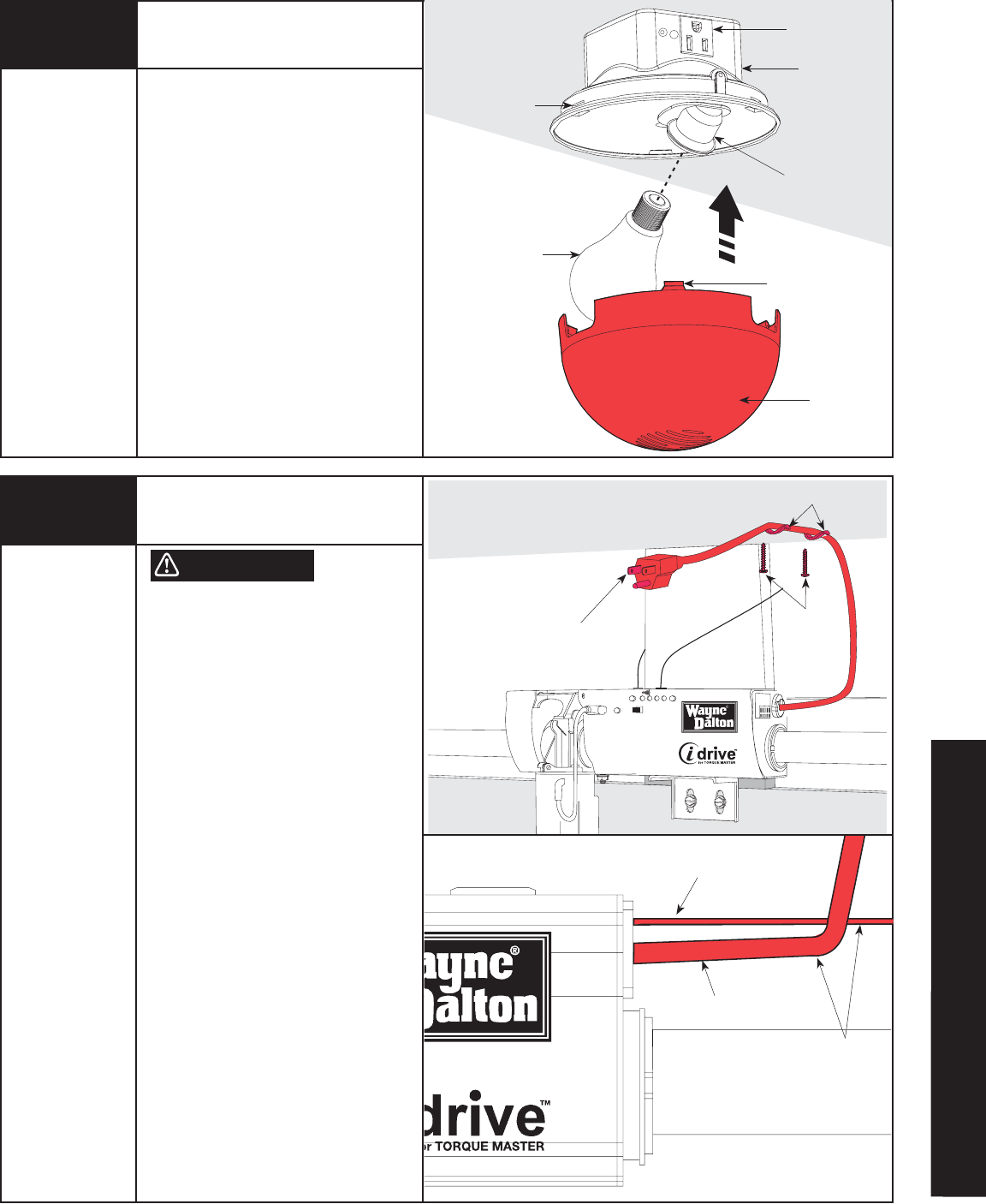
Light Fixture
Diffuser
75W (MAX)
Light Bulb
(Not Included)
Power Outlet
Snap Tabs
Mating Slots
Screw a 75W (maximum) light bulb into
light socket and snap diffuser into light
fixture.
When assembling diffuser, make sure all
three snap tabs are aligned and fully
snapped into the three mating slots of the
light fixture.
Turn receptacle power back on at fuse/
breaker box. The light should blink one
time when the power is turned back on.
NOTE: An accessory power outlet
receptacle (600 Watt Maximum) is
provided as part of the light fixture.
Attaching Diffuser
TO REDUCE THE RISK OF ELECTRICAL
SHOCK, DO NOT CHANGE THE POWER
CORD PLUG IN ANYWAY.
The opener can be permanently wired. To
permanently wire the unit, see Permanent
Wiring option on page 40.
Plug the end of the power cord into the
closest grounding type receptacle
Otherwise, contact a service person for
further options. Excess power cord length
must be routed and contained safely away
from any moving parts.
As soon as power is applied to the opener,
it should beep two times.
NOTE: Do not permanently attach power
cord to building!
NOTE: Use only the flexible cable clips
supplied with the opener.
Connecting Opener
Power Cord
Plug Into Nearest
Power Outlet
Cable Clips
#6 x 7/8
Wood Screws
No Interference
Between Power
Cord and
Disconnect Cable
(Ceiling)
Light Socket
WARNING
Disconnect
Cable
Power Cord
18
19
Tools Needed:
Step Ladder
Tools Needed:
Phillips Head
Screwdriver
Step Ladder
FPO
PRE-OPERATION
26 Please Do Not Return This Product To The Store. Call Us Directly! Our Trained Technicians Will Answer Your Questions and/or Ship Any Parts You May Need.
You can reach us Toll Free at 1-888-827-3667 for Consumer Assistance or online at www.wayne-dalton.com
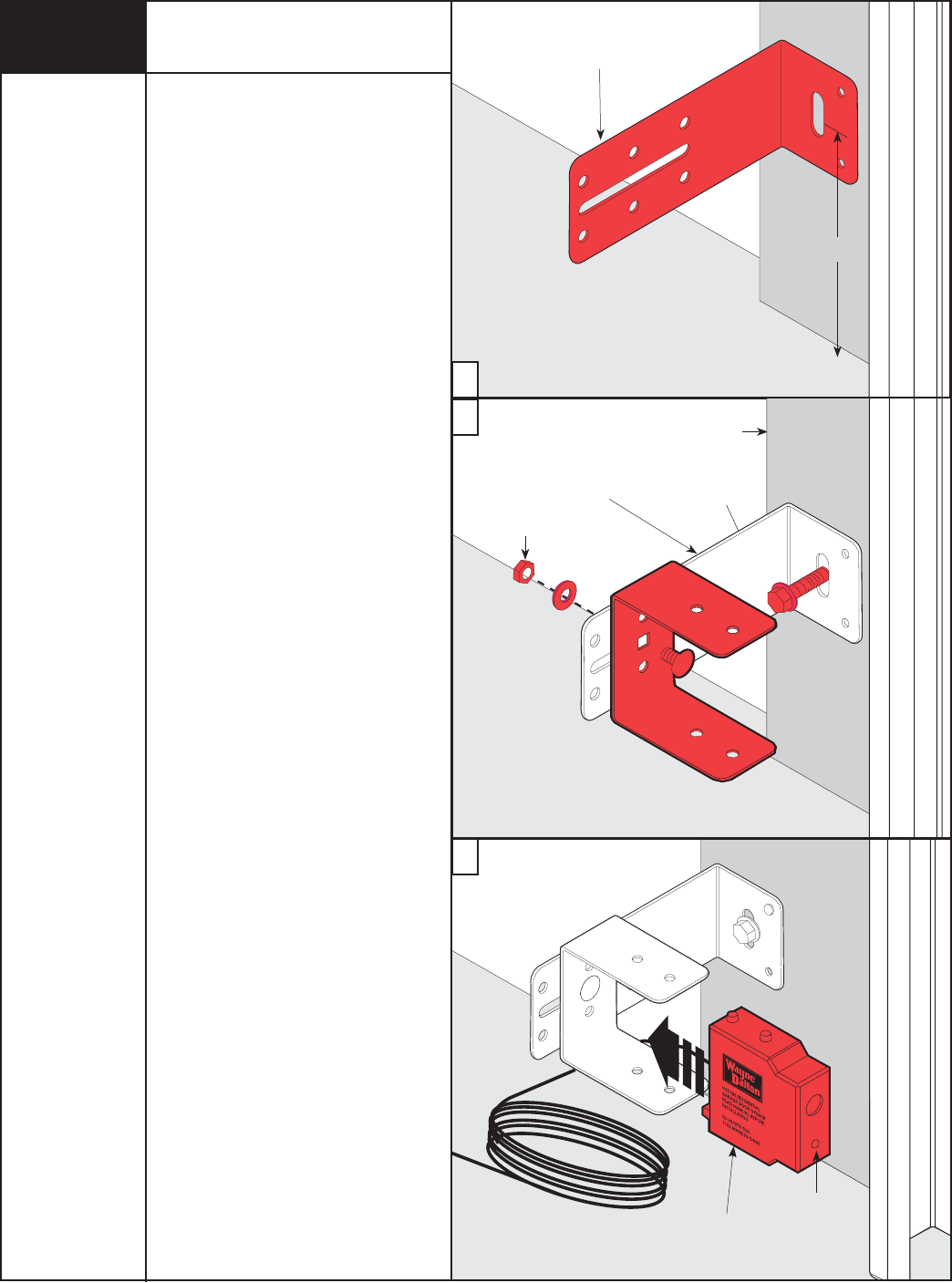
Receiving
Unit
LED
Washer
Nut
1/4”-20 x 1/2”
Carriage Bolt
5/16 x 1-1/2”
Lag Screw
Door Jam
U-Bracket
Wall Mounting
Bracket
NOTE (Per UL): Safety sensors are
required if opener is installed on a non-
pinch resistant door. If your door is pinch
resistant, skip this step and proceed with
Step 23.
a. Select and mark with a pencil, a suitable
mounting location no more than
5 inches above the floor to the center
line of wall mounting bracket. The safety
sensors should be mounted as close to
the door track or inside edge of the door
as possible to offer maximum entrapment
protection. It is very important that both
wall mounting brackets be mounted at
the same height for proper alignment.
IMPORTANT! BOTH WALL BRACKETS
MUST BE MOUNTED AT THE SAME HEIGHT
FOR PROPER ALIGNMENT.
b. Drill pilot holes, using a 3/16” drill bit.
Using two 5/16” x 1-1/2” lag screws,
permanently mount the wall mounting
brackets to both door jambs. In some
installations it may be necessary to
attach a wooden spacer to the wall to
achieve the required alignment.
Attach the “U” brackets to the wall
mounting brackets with 1/4”-20 x 1/2”
carriage bolts, washers and nuts.
Insert the bolts from the inside of the
“U” bracket and hand-tighten.
c. Attach the sending and receiving safety
sensors to the “U” brackets by inserting
all three tabs into the respective holes.
IMPORTANT! IDENTIFY WHICH SIDE OF
THE GARAGE DOOR IS EXPOSED TO THE
MOST SUNLIGHT. MOUNT THE SENDING
UNIT (UNIT WITHOUT LED) ON THE SIDE
WHICH IS EXPOSED TO THE MOST SUN.
SUNLIGHT MAY AFFECT THE SAFETY
SENSORS, AND THIS POSITIONING WILL
HELP REDUCE THE ADVERSE EFFECT
SUNLIGHT MAY HAVE ON THE SENSOR UNIT.
Safety Sensors Installation
8000 Series Doors
(Not Required On 9000 Series Doors)
a
b
c
Wall Mounting
Bracket
5”
20
Tools Needed:
Tape Measure
Power Drill
3/16" Bit
7/16” Socket
Driver
7/16” Wrench
Pencil