Wayne Dalton 0001715 TORQUE MASTER i-DRIVE PRO User Manual INSTALLATION GUIDE 4
Wayne Dalton Corporation TORQUE MASTER i-DRIVE PRO INSTALLATION GUIDE 4
Contents
- 1. INSTALLATION GUIDE 1
- 2. INSTALLATION GUIDE 2
- 3. INSTALLATION GUIDE 3
- 4. INSTALLATION GUIDE 4
INSTALLATION GUIDE 4

5015 B.U. Bowman Drive Buford, GA 30518 USA Voice: 770-831-8048 Fax: 770-831-8598
Certification Test Report
908.42 MHz Low Power Communication Device Transceiver
372 MHz Discrete Receiver
FCC ID: KJ8-0001715
IC: 3540A-0001715
FCC Rule Part: 15.249
IC Radio Standards Specification: RSS-210
ACS Report Number: 07-0186 - 15C
Manufacturer: Wayne-Dalton Corporation
Model: 3790-Z
Installation Guide
Section4
27
Please Do Not Return This Product To The Store. Call Us Directly! Our Trained Technicians Will Answer Your Questions and/or Ship Any Parts You May Need.
You can reach us Toll Free at 1-888-827-3667 for Consumer Assistance or online at www.wayne-dalton.com
P
E
12
S1S2 S3 S4
Learn
D
Controls
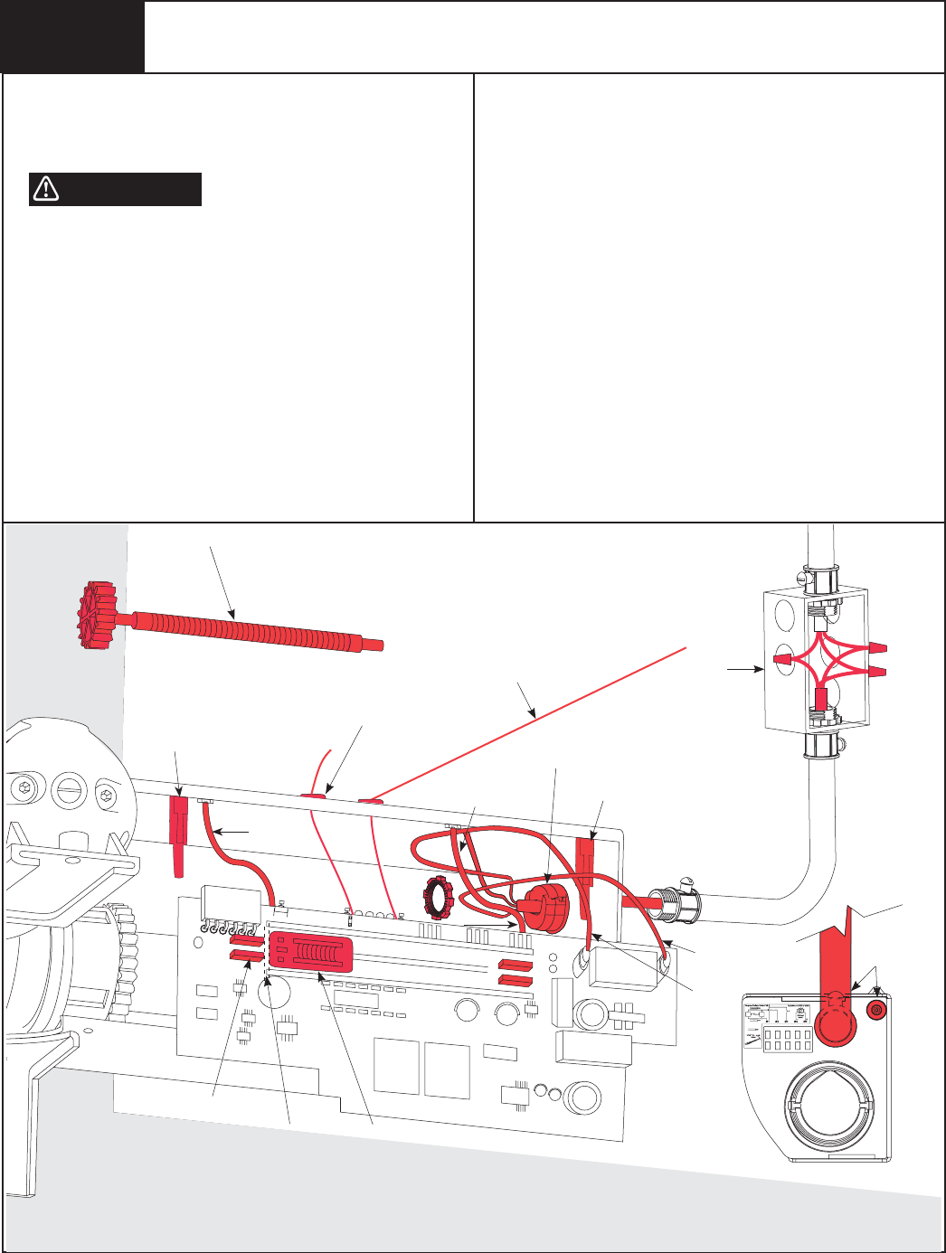
Wire Routing
21
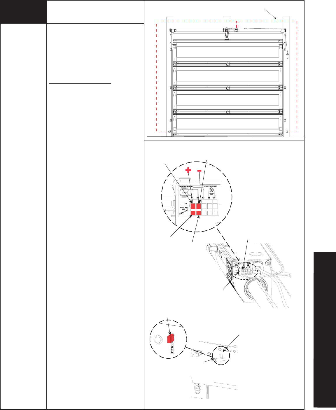
Uncoil wires from photoelectric sensors and route
wires up garage wall and along door header
towards the right side of the opener
.
Route wires behind torque tube and tack wires in
place with insulated staples (not supplied).Take
care to run wires in a location where they will not
interfere with the operation of the door.
Do Not Staple Through Wire.
NOTE: If wires must be lengthened or spliced
use wire nuts or suitable connectors.
NOTE: Take care to run wires in a location where
they will not interfere with the operation of the
door and do not staple through wire.
Connect photoelectric sensors to the opener
terminal block on right side of the opener. Sepa-
rate wire ends and strip about 1/2” of insulation
off each of the wire ends.
Insert a 3/32” (2.5mm) max. width fl atblade
screwdriver into the lower hole #1 of the
terminal block. Twist screwdriver to open wire
clamp in upper hole #1 of terminal block. Insert
both sender and receiver solid white wires into
upper hole #1 until the wires bottom out and
release screwdriver tension. Insert and twist
screwdriver in lower hole #2 and insert both
sender and receiver wires (white with black
stripe) into upper hole #2 until wires bottom
out and release screwdriver tension. Be sure to
observe polarity.
Once wires are connected, install jumper
through the front opener cover on to the pins
labeled PE.
IMPORTANT! KEEP SENDER/RECEIVER WIRES
AWAY FROM MOVING COMPONENTS.
Lightly pull on external wires to test for secure
connection. Check that the wires are stapled in
place and staples have not cut wire
insulation.
Insert screw
driver into
lower hole #1
Insert wires
into upper
hole #2
Insert wires
into upper
hole #1
Insert screw
driver into lower
hole #2
White wires with
black stripe
Solid white wires
RIGHT HAND SIDE VIEW OF OPENER
Jumper
installed
Jumper
Pins labeled
“PE”
VIEW OF THE OPENER FROM THE FRONT
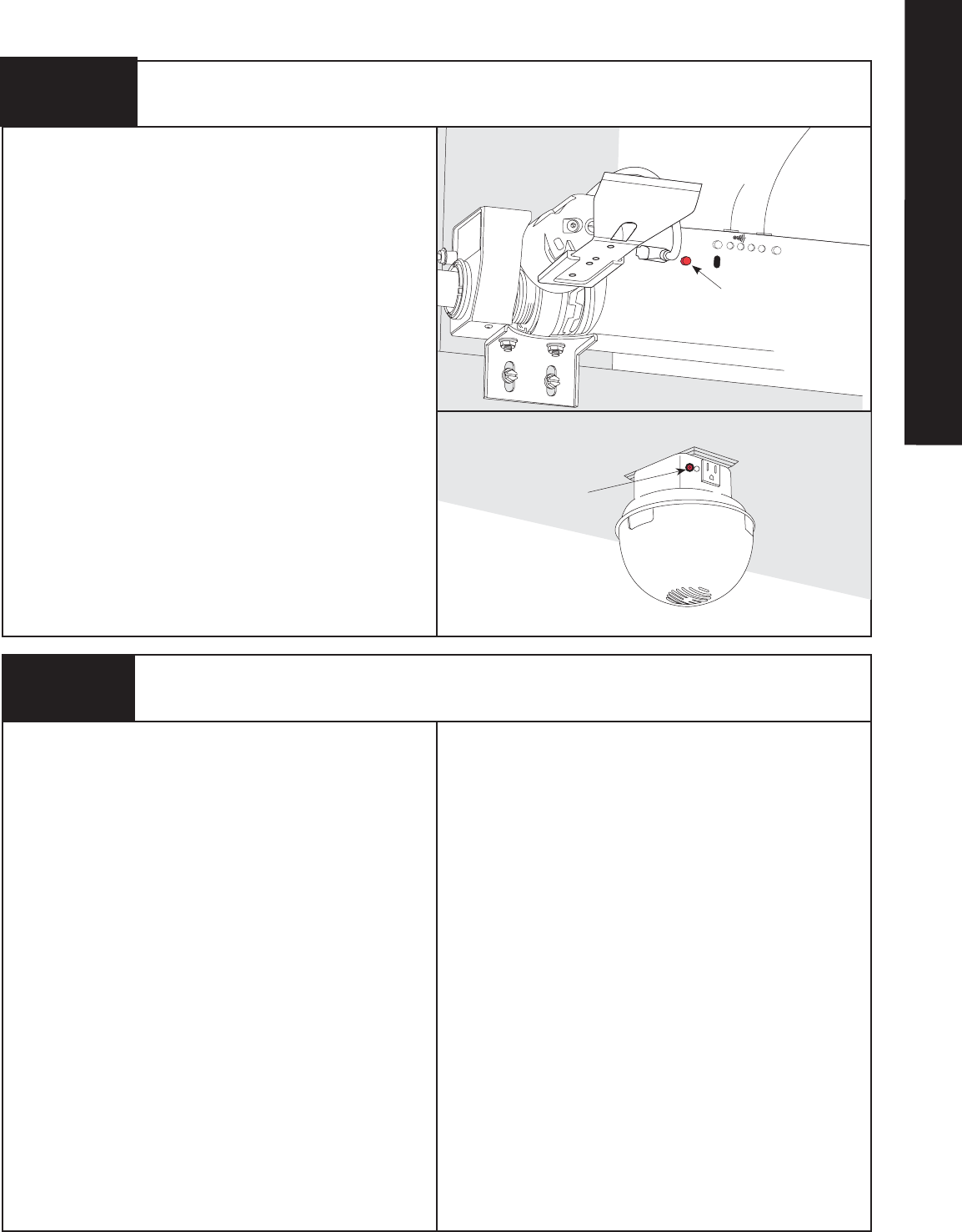
Tools Needed:
Flat Tip
Screwdriver
Pliers/Wire
Cutters
Sensor Wire Installation
(Required on 8000 Series Doors)
PRE-OPERATION
28 Please Do Not Return This Product To The Store. Call Us Directly! Our Trained Technicians Will Answer Your Questions and/or Ship Any Parts You May Need.
You can reach us Toll Free at 1-888-827-3667 for Consumer Assistance or online at www.wayne-dalton.com
S1 S2 S3 S4
Learn Delete
Controls
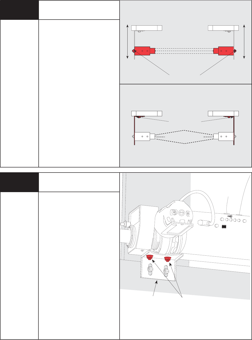
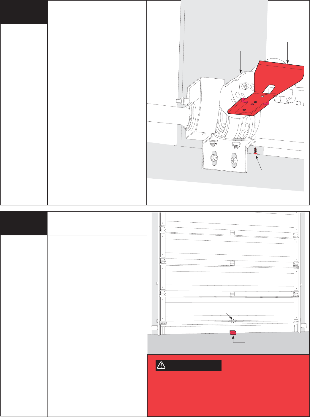
With the emergency disconnect still in the
manual door operated position, manually
raise the door to the fully open position.
Then, manually lower the door to the fully
closed position verifying freedom of
movement and good door balance.
Tighten both 1/4”-20 flange nuts, securing
the opener to the support bracket.
NOTE: Good door balance and freedom of
movement are essential for proper opener
performance. If door is heavy to lift, hard to
close or if door sticks or binds in
the track, make proper adjustments now.
Securing the Opener
and Checking for Obstructions
Align the safety sensors by moving the
sending and receiving units in or out until
the alignment light on the receiving unit
comes on. The 1/4”-20 carriage bolt can be
loosened to move the safety sensor in or
out, as required. If you have difficulty
aligning the beams, check that both
mounting brackets are mounted at the
same height and remount if necessary.
Additional minor adjustments can be made
by slightly bending the mounting brackets.
Once the alignment light comes on, tighten
all bolts and mounting screws. Finish
securing all wires making sure not to break
or open any of the conductors. Loop and
secure any excess wire.
Safety Sensor Alignment
1/4”-20 Carriage
Bolts
In
Out
In
Out
Top View
Top View
For this adjustment, bend
Bracket at wall mount
1/4” - 20
Flange Nuts
Support
Bracket
Tools Needed:
Pliers
22
23
Tools Needed:
7/16” Wrench
Step Ladder
29
Please Do Not Return This Product To The Store. Call Us Directly! Our Trained Technicians Will Answer Your Questions and/or Ship Any Parts You May Need.
You can reach us Toll Free at 1-888-827-3667 for Consumer Assistance or online at www.wayne-dalton.com
T
o
O
p
e
r
a
t
e
D
o
o
r
Press
Here
TO AVOID INJURY, NO ONE SHOULD
CROSS THE PATH OF A MOVING DOOR!
The profile routine automatically sets the
door open and close limits and calibrates
obstruction sensing. During the profile
routine, the door will move up and down
twice.
NOTE: If an object such as a ceiling beam
obstructs the door from opening completely,
skip this step. Set a Custom Upper Limit, see
Step 26.
NOTE: The door must be in its fully closed
position and the disconnect handle must
be in the motor operated position (upper
position) to initiate the profile routine.
NOTE: Profile routine will not run if safety
sensors are not aligned (only if required
installation).
Press and hold the profile button for
five (5) seconds. The opener will beep
twice, release the profile button, indicating
the activation of the profile routine. The door
will now move to the fully open position and
stop, beep twice and then the door will close
completely.
Next, the door will go through one more up/
down cycle. Once this is complete, the door
limits are set and the profile is complete.
NOTE: Upon successful completion proceed
to Step 27.
Profile Routine
(Standard Upper Limit)
Programming Light Fixture Program Button
Light Button
Profile
Button
Tools Needed:
None
LED
WARNING
Press the red program button on the light
fixture. The LED on the light fixture will turn
on and remain on for 30 seconds
or until a opener is learned to the light
fixture. The incandescent lamp will also turn
on when program button is pushed.
Press the light button on the wall station.
This must be done within 30 seconds of
pressing the program button on the light
fixture. The light fixture lamp and LED will
blink three times to indicate successful
programming. The light fixture can now be
turned on and off from this wall station.
NOTE: In order to program the opener to
the light fixture, the installer must have the
wall station already programmed to the
opener.
24
25
Tools Needed:
Step Ladder FPO
PRE-OPERATION
30 Please Do Not Return This Product To The Store. Call Us Directly! Our Trained Technicians Will Answer Your Questions and/or Ship Any Parts You May Need.
You can reach us Toll Free at 1-888-827-3667 for Consumer Assistance or online at www.wayne-dalton.com
Detent Pin
Adjustment Screw
TO AVOID INJURY, NO ONE SHOULD
CROSS THE PATH OF A MOVING DOOR!
NOTE: If no obstruction interferes with a
standard upper limit, skip this step.
NOTE: The door must be in its fully closed
position and the disconnect handle must be
in the motor operated position (upper
position) to initiate the profile routine.
NOTE: Install profile will not run if safety
sensors are not aligned (Only if required for
your door).
Press and hold the profile button for
five (5) seconds. The opener will beep
twice, release the profile button, indicating
the activation of the profile routine.
When the door moves to the desired upper
limit, press and hold the Up/Down button on
the wall station until the door stops. Next,
the door will close completely. The Up/Down
button (when door is closed) can be
activated by pressing center of flip cover.
Next, the door will go through one more Up/
Down cycle. Once this is complete, the door
limits are set and the profile is complete.
Alternately, once an profile routine has been
successfully completed, disconnect door
and manually move to desired upper limit.
Re-connect door and press and hold the
profile button for five (5) seconds. The
door will close, open and close to complete
the profile routine with the new custom
upper limit.
NOTE: For a more precise location of the
custom upper limit, see “Customizing the
Settings” on page 39.
The amount of pressure the opener
uses to pivot the motor downward is
preset at the factory via the detent pin
adjustment screw.
Due to variations in door installations,
a detent pin adjustment may need to
be made in order to insure proper pivoting
of the motor.
IMPORTANT! FOR SYSTEM SECURITY:
THE MOTOR IS DESIGNED TO PIVOT DOWN
AFTER THE DOOR CLOSES COMPLETELY. IF
THE MOTOR DOES NOT PIVOT OR PIVOTS
TOO SOON, THE DETENT PIN ADJUSTMENT
SCREW MAY NEED TO BE ADJUSTED IN
ORDER FOR THE DOOR LOCK FEATURE TO
WORK PROPERLY.
Adjusting Detent
Install Routine
(Custom Upper Limit)
Profile
Button
Up/Down
Button
Tools Needed:
None
WARNING
26
27
Tools Needed:
Flat Tip
Screwdriver
Step Ladder
31
Please Do Not Return This Product To The Store. Call Us Directly! Our Trained Technicians Will Answer Your Questions and/or Ship Any Parts You May Need.
You can reach us Toll Free at 1-888-827-3667 for Consumer Assistance or online at www.wayne-dalton.com
NOTE: If you have a low headroom double
track system, skip this step and continue
with Step 29.
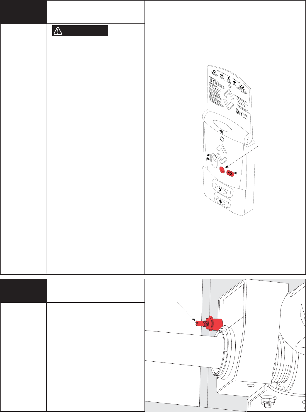
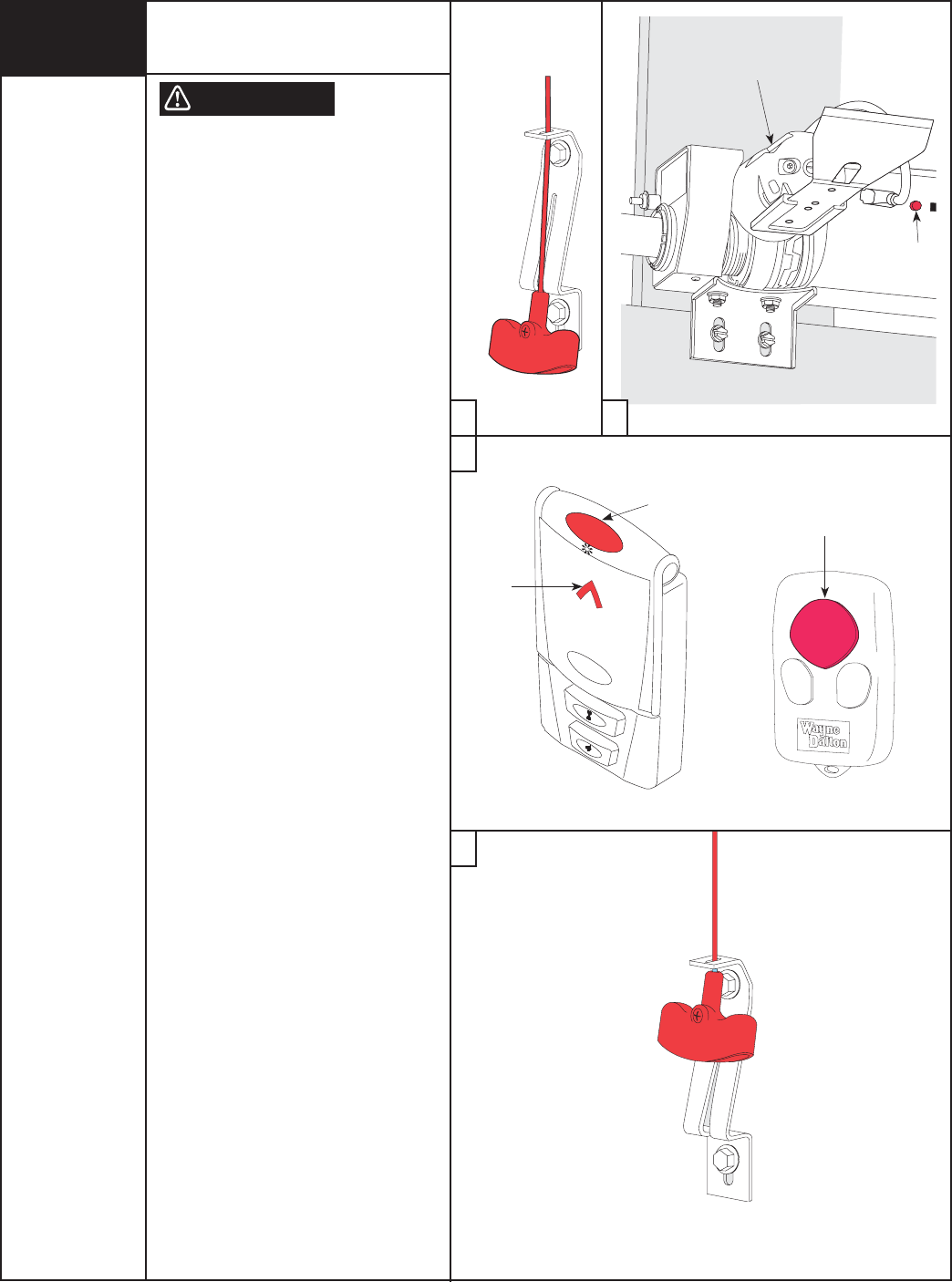
Place the emergency disconnect in the manual
operated position, Motor will pivot to the up
position (see Step 10).
Insert the lock arm into the motor groove and
align with the proper hole depending on your
track radius. To determine the Wayne-Dalton
track radius being used, measure the length of
the flagangle and Torquemaster® end bracket
and compare to the diagram on the right (all
Portland tracks are stamped with radius on the
side of the track).
Mt. HOPE/
PENSACOLA
15” RADIUS
21-1/8”
Mt. HOPE/
PENSACOLA
12” RADIUS
19-3/4”
PORTLAND
TRACK
20-3/4”
Lock
Arm
Position
Track Type
WD - Mt. Hope &
Pensacola
PO - Portland
Track Radius Door Model
1
WD
WD
PO
PO
15”(380mm)
12”(305mm)
12”
10”
9700
8000, 9000
9000 Series
8000, 9000
2 PO 12” 8000 Series
3WD
PO
15”(308mm)
14”
8000, 9000
9000 Series
4 PO 14” 8000 Series
Adjusting Detent
(Continued)
Tools Needed: a. If the motor does not pivot down, or only
pivots down partially, the detent pin is set
too hard.
Using a flat tip screwdriver, turn the
detent pin counterclockwise in 1/8
turn increments.
Operate the door to confirm adjustment.
Repeat procedure until motor pivots
to full down position when the door
is completely closed.
b. If the motor pivots down prematurely
(before the door is completely closed) or
if the motor is “slapping” too aggressively
against the top of the door, the detent pin
is set too soft.
Using a flat tip screwdriver, turn the
detent pin clockwise in 1/8 turn
increments. Operate the door to
confirm adjustment.
Repeat procedure until motor pivots
to full down position when the door
is completely closed.
Lock Arm Installation
a
b
1
2
Lock
Arm
Motor
3
4
Motor
Groove
28
Tools Needed:
Tape Measure
Step Ladder
PRE-OPERATION
32 Please Do Not Return This Product To The Store. Call Us Directly! Our Trained Technicians Will Answer Your Questions and/or Ship Any Parts You May Need.
You can reach us Toll Free at 1-888-827-3667 for Consumer Assistance or online at www.wayne-dalton.com
Lock Arm Installation
(Continued)
Once track radius has been determined,
secure the lock arm to the motor with
(1) 5mm x .8mm phillips pan head screw.
NOTE: If unsure of track radius, begin with
lock arm in position 1.
After assembly of the lock arm, manually
raise and lower the door and verify that the
lock arm does not interfere with the door. If
there is interference between the door and
the lock arm, see Page 43 for lock arm
troubleshooting.
NOTE: Do not operate the door or opener if
there is interference between the lock arm
and the door.
Reconnect the door to the motor operated
position. Activate a motor operated up/down
cycle to confirm clearance.
Lock Arm
Motor
5mm x 8mm
Phillips
Pan Screw
Tools Needed:
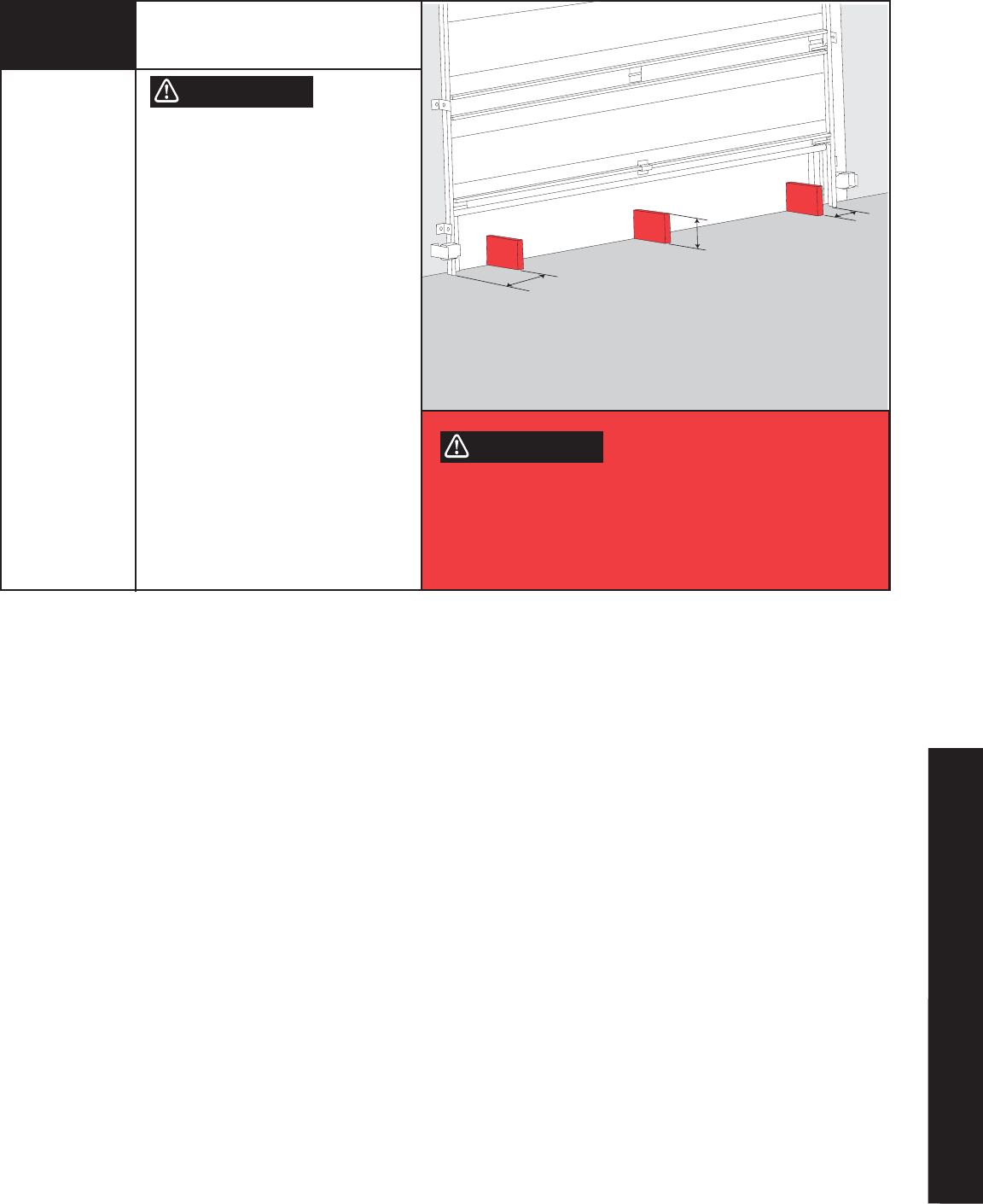
Contact Obstruction Test
After installing the opener, the door must
reverse when it contacts a 1-1/2” high
object (or a 2 x 4 board laid flat) on the
garage floor.
Using the wall station, activate the door
to the fully open position.
Place a 2 x 4 board flat on the garage
floor, under the door path.
Activate the door to the closed position
with the wall station. Upon contacting the
2 x 4 board, the door should stop, then
reverse direction within two seconds and
travel to the full open position.
If the door does not respond to the
required tests, repeat install routine Step
25 or 26, making sure the door is in the
fully closed position prior to activation.
Center Of Door
2 x 4 Laid Flat
On Floor
WARNING
Tools Needed:
2 x 4 Board
IF OPENER DOES NOT RESPOND PROPERLY TO THESE TESTS (STEPS
29 AND 30), DO NOT USE DOOR UNTIL A QUALIFIED SERVICE PERSON
HAS MADE NECESSARY ADJUSTMENTS/REPAIRS, OR SEVERE OR FATAL
INJURY COULD RESULT FROM OPERATING THE DOOR/OPENER.
29
33
Please Do Not Return This Product To The Store. Call Us Directly! Our Trained Technicians Will Answer Your Questions and/or Ship Any Parts You May Need.
You can reach us Toll Free at 1-888-827-3667 for Consumer Assistance or online at www.wayne-dalton.com
Tools Needed:
6” Height Object WHEN PERFORMING THIS PART OF THE
TEST, DO NOT PLACE YOURSELF UNDER
DESCENDING DOOR, OR SEVERE OR
FATAL INJURY MAY RESULT.
Starting with the door fully open, place
a 6” high object on the floor, in line with
sensors, one foot from the left side of
the door.
Activation of the opener with the wall
station Up/Down button should cause the
door to move no more than one foot, stop
and then reverse to fully open position.
Repeat this test with the 6” high object
placed at the center of the door and then
one foot from the right side of the door.
The 6” high object, when placed on the
floor in line with sensors, while door is
closing, should also cause the door to
reverse.
Testing the Safety Sensors
(If Installed)
12”
6”
12”
IF OPENER DOES NOT RESPOND PROPERLY TO THESE TESTS (STEPS
29 AND 30), DO NOT USE DOOR UNTIL A QUALIFIED SERVICE PERSON
HAS MADE NECESSARY ADJUSTMENTS/REPAIRS, OR SEVERE OR FATAL
INJURY COULD RESULT FROM OPERATING THE DOOR/OPENER.
WARNING
WARNING
30
PRE-OPERATION

❉
TO REDUCE THE RISK OF SEVERE
INJURY OR DEATH:
1. READ AND FOLLOW ALL INSTRUCTIONS.
2. Never let children operate or play with the door controls.
Keep remote controls away from children.
3. Always keep a moving door in sight and keep people and objects
away until it is completely closed. NO ONE SHOULD CROSS THE
PATH OF A MOVING DOOR.
4. NEVER GO UNDER A STOPPED, PARTIALLY OPEN DOOR.
5. Test the Door/Opener monthly. The garage door MUST reverse on
contact with a 1-1/2” high object (or a 2 x 4 board laid flat) on the
floor. The door MUST also reverse when a 6” high object is placed on
the floor in line with safety sensors. If Door/Opener fails these tests,
have adjustments/repairs made immediately. Failure to make
adjustments/repairs may cause severe or fatal injury.
6. When possible, use the Emergency Disconnect only when the door is
in the closed position. Be very cautious using the Emergency
Disconnect when the door is open. Weak or broken spring(s) may
allow the door to fall rapidly, causing a severe or fatal injury.
7. KEEP THE GARAGE DOOR PROPERLY BALANCED. See the owner’s
manual included with the door. An improperly balanced door could
cause a severe or fatal injury. Have a qualified service person make
repairs to the cables, spring assemblies, and other hardware.
8. SAVE THESE INSTRUCTIONS.
Door activation:
Upon activation by either the Wall Station Up/Down Button or
Transmitter, the door will move in the following manner:
1. If closed, the door will open. If open completely, the door will close. If
partially open, the door will close.
2. If closing, the door will stop, reverse, and return to the open position.
Next activation will close the door.
3. If opening, the door will stop. Next activation will close the door.
4. If an obstruction is encountered or an out-of-balance condition is
detected while the door is closing, the door will reverse, return to the
open position, and the opener will beep 3 or 4 times. The next
activation will close the door.
5. If an obstruction is encountered or an out-of-balance condition is
detected while opening the door, the door will stop. The next
activation will close the door.
6. When door is in motion any button on the wall station functions the
same as the Up/Down button.
ALWAYS KEEP MOVING DOOR IN SIGHT AND KEEP PEOPLE AND
OBJECTS AWAY UNTIL IT IS COMPLETELY CLOSED. TO PREVENT A
SEVERE OR FATAL INJURY, AVOID STANDING IN A OPEN DOOR WAY
OR WALKING THROUGH THE DOORWAY WHILE THE DOOR IS
MOVING.
NEVER LET CHILDREN OPERATE DOOR OR PLAY WITH THE DOOR
CONTROLS. KEEP REMOTE CONTROLS AWAY FROM CHILDREN.
FATAL INJURY COULD RESULT SHOULD A CHILD BECOME TRAPPED
BETWEEN THE DOOR AND FLOOR.
KEEP THE GARAGE DOOR PROPERLY BALANCED. AN IMPROPERLY
BALANCED DOOR COULD CAUSE SEVERE OR FATAL INJURY. HAVE A
QUALIFIED SERVICE PERSON MAKE ADJUSTMENTS/REPAIRS TO
CABLES, SPRING ASSEMBLIES, AND OTHER HARDWARE.
Emergency Disconnect:
THE EMERGENCY DISCONNECT SHOULD ONLY BE USED WHEN DOOR
IS CLOSED. USE EXTREME CAUTION IF OPERATING THE EMERGENCY
DISCONNECT ON AN OPEN DOOR. WEAK OR BROKEN SPRING(S) MAY
ALLOW THE DOOR TO FALL RAPIDLY, CAUSING SEVERE OR FATAL
INJURY.
The opener is equipped with an emergency disconnect that allows the
door to be moved manually and independently from the opener.
With the door closed, pull down on the disconnect handle and place the
handle under the lower section of the handle bracket. This motion
causes the motor on the opener to pivot upwards and the opener to
disconnect from the torque tube.
Releasing the disconnect handle from the lower section on the handle
bracket and returning the handle to its original position will reconnect
the opener to the torque tube.
NOTE: The motor will not pivot down completely when the handle is
released. After one motorized up/down door cycle, the motor will once
again pivot down, and all cable slack will be taken up. The garage door
is not secured from forced entry until the motor is back in the down
position.
Disconnect Label: The label is located next to the disconnect handle.
The label shows the handle in both the motor operated and manual
operated positions. View on the left side of the label shows the handle
position when the opener is engaged to the torque tube. The view on the
right side of the label shows the handle when the opener is disconnected
from the torque tube.
IMPORTANT SAFETY INSTRUCTIONS
WARNING WARNING
WARNING
WARNING
WARNING
34
Please Do Not Return This Product To The Store. Call Us Directly! Our Trained Technicians Will Answer Your Questions and/or Ship Any Parts You May Need.
You can reach us Toll Free at 1-888-827-3667 for Consumer Assistance or online at www.wayne-dalton.com
❉
Up-Down Button:
Momentarily pressing the Up/Down button activates the door. If an
out-of-balance condition causes the door to stop while opening or
reverses the door while closing, apply constant pressure to the
Up/Down button until the door is fully open or closed. This will allow
the opener to move the door in an out of balance condition, until the
problem is corrected (see Troubleshooting). The Up/Down button
(when unit is closed) can be activated by pressing flip cover.
THE SEVERE OUT-OF-BALANCE CONDITION MUST BE CORRECTED
IMMEDIATELY. FAILURE TO MAKE ADJUSTMENTS/REPAIRS, COULD
RESULT IN SEVERE OR FATAL INJURY.
Light Button:
Momentarily pressing the Light Button turns on the light fixture. The
light fixture will remain on until either the Light Button is pressed again
or the door is activated. The light fixture automatically turns on with a
door activation and remains on for five minutes. Pressing the light
fixture button before the five minutes has elapsed will turn off the light
fixture. While the door is in motion, the Light Button functions identically
as the Up/Down button, stopping or reversing the door immediately.
Timer Button:
Momentarily pressing the Timer Button causes a delayed activation of a
stationary fully open door. The opener will signal seven beeps (approx.
8 seconds) then beep constantly for two seconds prior to closing the
door, allowing time to exit the garage when the opener is in the timer
mode. Pressing any button, except for the profile button while the
opener is beeping cancels the timer mode.
NOTE: The Timer feature will only function with the door in the
full open position. Pressing the Timer Button with a stationary
door in any other position will cause the opener to beep four
times and the door will not be activated.
While the door is in motion, the Timer Button functions identically as
the Up/Down button, stopping or reversing the door immediately.
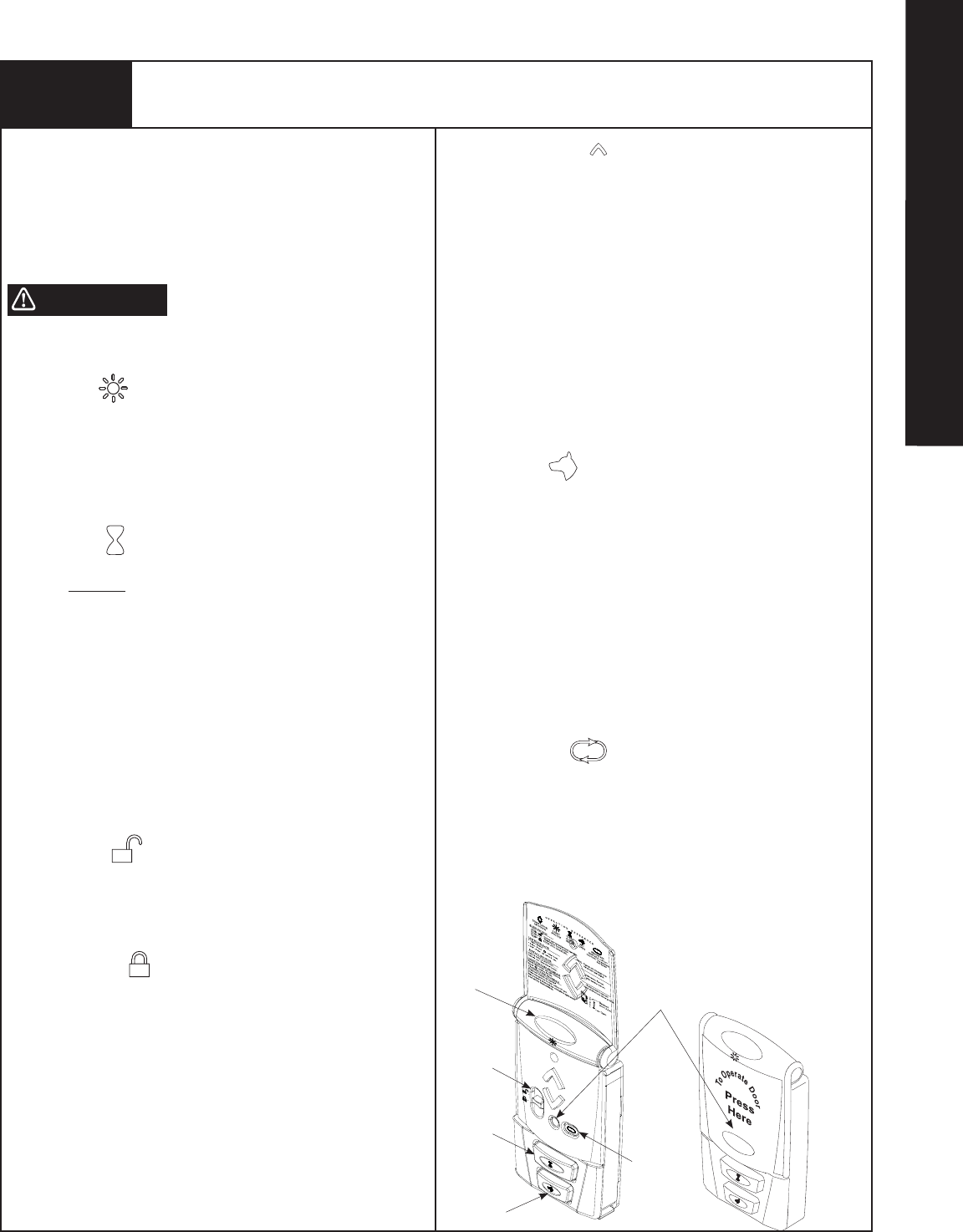
Slide Switch:
The Slide Switch has two positions: Normal, and Door lock.
Normal position:
Move the Slide Switch to normal position for all normal functions of the
opener. The normal position will cancel the door lock feature.
NOTE: When the Slide Switch is moved to the unlocked
position the opener will beep once.
Door Lock position:
If the door is stopped (fully open, fully closed or partially open) move
the Slide Switch to the door lock position to suspend all normal
functions of the opener. The opener will remain completely disabled
and non-operational in this mode. All wall stations, transmitters and
keyless entry units are ignored until the Slide Switch is moved to the
normal position. If the door is moving when the Slide Switch is moved
to the door lock position, the door lock mode is not activated and all
functions of the opener remain active.
NOTE: When the Slide Switch is moved to the locked position
the opener will beep twice.
Operating the Wireless Wall Station
Backlit LED Light:
The red LED blinks intermittently to help you locate the wall
station in a dark garage. This blink rate can be changed for longer
battery life or can be turned off. The default blink rate is one blink
every 3 seconds. For longer battery life the blink rate can be
changed to blink once every 6 seconds. To change the blink rate,
remove the battery cover and remove one battery. Re-install the
battery and within 2 seconds, press the Light button. Re-install
the battery cover.
For longest battery life, the blink can be turned off. To turn off
the blink, remove the battery cover and remove one battery.
Re-install the battery and within 2 seconds, press the pet button.
Re-install the battery cover.
NOTE: The wall stations red LED will light while any wall
station button remains pressed.
Pet Position:
Pressing the Pet button opens a closed door to a preset position
between eight and thirty inches above the floor, allowing pets to
enter and exit the garage without the door being fully open. The
door must be fully closed to activate the pet open feature.
Pressing the Pet button with a stationary door in the pet open
position will cause the door to close. Pressing the Up/Down
button while the door is in the pet position will cause the door to
open. While the door is in motion, the pet button functions
identically to the Up/Down button, stopping or reversing the door
immediately. The pet feature allows for custom setting of the pet
position door height. See Customizing the Settings on page 38.
NOTE: A door in the “pet position” (open 8-30 inches) is not
locked and should not be used as a secured door position.
Profile Routine:
Press and hold the Profile button for 5 seconds to initiate the
“Profile Routine”. See Customizing the Settings on page 38.
NOTE: The wall stations red LED will light while any wall station
button remains pressed. See Maintenance section for battery
replacement.
Pet Button
Light Button
Up/Down Button
Timer Button
Profile Button
Slide Switch
WARNING
35 Please Do Not Return This Product To The Store. Call Us Directly! Our Trained Technicians Will Answer Your Questions and/or Ship Any Parts You May Need.
You can reach us Toll Free at 1-888-827-3667 for Consumer Assistance or online at www.wayne-dalton.com
OPERATION

❉Programming HomeLink® System to the Torquemaster® idrive® (Primary)
Programming/Training HomeLink® Unit
GARAGE DOOR MAY OPERATE DURING PROGRAMMING. TO AVOID
POSSIBLE SEVERE OR FATAL INJURY, PLACE THE EMERGENCY
DISCONNECT HANDLE IN THE MANUAL OPERATED POSITION.
1. Pull the manual disconnect to put the opener in the disengaged
position.
2. Verify the HomeLink® unit has an empty channel – press the
desired HomeLink® button and observe the LED – if it flashes
slowly, the channel is empty and ready for programming. If
pressing the desired channel/button causes the LED to blink
rapidly, or come on without blinking this channel is already
programmed. You either need to choose a different channel/
button on the HomeLink®, or perform Step 3 below.
3. OPTIONAL – To completely clear all channels on the HomeLink®
unit, press and hold the two outside buttons on the HomeLink®
unit until the HomeLink® LED light begins to flash rapidly
(approx. 20 seconds), then release both buttons. (Do not perform
this step to train additional hand-held transmitters.) NOTE: This
operation erases all previously learned transmitters and you will
need to re-teach any other transmitters to your HomeLink® unit.
4. Hold the end of the Wayne Dalton hand-held transmitter
approximately 1 to 3 inches away from the HomeLink® surface –
keeping the HomeLink® indicator light in view.
5. Simultaneously press and hold the Wayne Dalton transmitter
large button and desired button on the HomeLink® module,
continue to hold both buttons. In less than 10 seconds the LED
on the HomeLink® module will either go solid or give a single
quick flash, release both buttons when either occur.
NOTE: If this procedure is unsuccessful, perform Alternate procedure
on next page.
Teaching HomeLink® to the idrive® opener
6. Press and release the red program button on the idrive® opener.
The idrive® unit will beep once, indicating that it is ready to learn.
NOTE: The idrive® will remain in the learn mode for 30 seconds.
7. Press the HomeLink® button used in Step 5 above for 1 to 3
seconds. The idrive® will beep indicating a successful learn.
8. Return the manual disconnect to the engaged position.
9. Press the HomeLink® button once more to operate the door.
NOTE: The first transmitter command after programming will only move
the door through a six inch up/down cycle. Normal door operations will
occur on the second use of the transmitter.
NOTE: This step can only be done on automobiles equipped with the
HomeLink® system.
NOTE: Programming HomeLink® requires a Wayne-Dalton Transmitter
that is programmed to the opener (the wallstation and transmitter(s)
supplied with the opener, come pre-programmed from the factory). Any
additional wallstation(s) or transmitter(s) will need to be programmed to
the opener, see page 41.
IMPORTANT! Use the programming instructions provided with your
vehicle first. Follow these instructions if the HomeLink® unit does not
learn the transmitter, when using the vehicle’s instructions.
NOTE: If Primary programming does not work then use the Alternate
procedure on next page.
NOTE: Vehicle may need to be in accessory position when
programming. Check car owner’s manual.
NOTE: HomeLink® is a registered trademark of Johnson Controls.
WARNING
36
Please Do Not Return This Product To The Store. Call Us Directly! Our Trained Technicians Will Answer Your Questions and/or Ship Any Parts You May Need.
You can reach us Toll Free at 1-888-827-3667 for Consumer Assistance or online at www.wayne-dalton.com

❉Programming HomeLink® System to the Torquemaster® idrive® (Alternate)
Programming/Training HomeLink® Unit
GARAGE DOOR MAY OPERATE DURING PROGRAMMING. TO AVOID
POSSIBLE SEVERE OR FATAL INJURY, PLACE THE EMERGENCY
DISCONNECT HANDLE IN THE MANUAL OPERATED POSITION.
1. Pull the manual disconnect to put the opener in the disengaged
position.
2. Press and hold the two outside buttons on the HomeLink®
unit until the HomeLink® light begins to flash rapidly (approx. 20
seconds), then release both buttons. (Do not perform this step to
train additional hand-held transmitters.) NOTE: This operation
erases all previously learned transmitters and that you need to
re-teach any other transmitters to your HomeLink® unit by
repeating steps 3 - 6 below.
3. Hold the end of the Wayne®Dalton hand-held transmitter
approximately 1 to 3 inches away from the HomeLink® surface –
keeping the HomeLink® indicator light in view.
4. Use the large button on the Wayne Dalton transmitter.
Simultaneously press and hold desired Homelink® button and the
Wayne Dalton transmitter large button. Continue to press both
buttons counting LED flashes on the HomeLink® module;
between 50 to 60 LED flashes the LED will either come on solid
or do one “quick flash”; when either of these occur release both
Wayne Dalton transmitter and HomeLink® buttons.
Teaching HomeLink® to the idrive® Opener
5. Press and release the red program button on the idrive® opener.
The idrive® unit will beep, indicating that it is ready to learn.
NOTE: The idrive® will remain in the learn mode for 30 seconds.
6. Press the HomeLink® button used in Step 4 above for 1 to 3
seconds. The idrive® will beep indicating a successful learn.
7. Return the manual disconnect to the engaged position.
8. Press the HomeLink® button once more to operate the door.
NOTE: The first transmitter command after programming will only move
the door through a six inch up/down cycle. Normal door operations will
occur on the second use of the transmitter.
NOTE: This Step can only be done on automobiles equipped with the
HomeLink® system.
NOTE: Programming HomeLink® requires a Wayne-Dalton Transmitter
that is programmed to the opener (the wallstation and transmitter(s)
supplied with the opener, come pre-programmed from the factory). Any
additional wallstation(s) or transmitter(s) will need to be programmed to
the opener, see page 41.
IMPORTANT! Use the programming instructions provided with your
vehicle first. Follow these instructions if the HomeLink® unit does not
learn the transmitter, when using the vehicle’s instructions.
NOTE: Vehicle may need to be in accessory position when
programming. Check car owner’s manual.
NOTE: HomeLink® is a registered trademark of Johnson Controls.
WARNING
37 Please Do Not Return This Product To The Store. Call Us Directly! Our Trained Technicians Will Answer Your Questions and/or Ship Any Parts You May Need.
You can reach us Toll Free at 1-888-827-3667 for Consumer Assistance or online at www.wayne-dalton.com
OPERATION
❉Customizing the Settings
Custom pet position:
Normal install routine sets the pet position to approximately 8 inches
above the ground. The pet opening height may be changed to open
anywhere between 8” and 30” above the ground. To change the
automatic pet opening height refer to the following procedure:
a. After completion of the normal install routine, with the door in the
closed position, place the disconnect handle in the manual operated
position.
Manually position the door to the desired pet opening height
(between 8” and 30” above ground) and return disconnect handle to
the motor operated position.
b. Move the slide switch from the NORMAL (Unlock) position to
the DOOR LOCK (Lock) position and then back to the NORMAL
(Unlock) position. The opener will beep once. The pet button is
now programmed to automatically open the door to this custom
height.
NOTE: The opener will NOT accept programmed pet lock position if
door is below 8” or higher than 30”.
NOTE: Activation of the normal install routine will reset the pet position
to the default 8” target height. For use of the pet button see operation
section.
Multi-Door Programming:
Momentarily pressing the button programmed in the transmitter
programming step activates the door. Other buttons can also be
programmed to activate different doors, for multi-door installations.
Each button or a combination of two buttons pressed simultaneously
can be programmed to activate a different door. Only one button at a
time can be programmed to activate a specific opener.
Custom Upper Limits
Disconnect door and manually move it to the desired upper limit.
NOTE: The door must be positioned more than halfway open.
Reconnect door.
Press and hold the profile button for 5 seconds. The opener will beep
twice, indicating the activation of the profile routine. The door will now
move to the closed position. Then, the door will open to the new upper
limit.
Next, the door will go down to the closed position. Once this is
complete, the door limits are set and the installation is complete.
For more profile options go to page 29 and 30.
NOTE: Before performing custom upper limit, first profile must be done
from closed position.
Pet Button
Profile Button
Up/Down Button
Up/Down Button
NORMAL
DOOR LOCK
38
Please Do Not Return This Product To The Store. Call Us Directly! Our Trained Technicians Will Answer Your Questions and/or Ship Any Parts You May Need.
You can reach us Toll Free at 1-888-827-3667 for Consumer Assistance or online at www.wayne-dalton.com
39
Please Do Not Return This Product To The Store. Call Us Directly! Our Trained Technicians Will Answer Your Questions and/or Ship Any Parts You May Need.
You can reach us Toll Free at 1-888-827-3667 for Consumer Assistance or online at www.wayne-dalton.com
S1 S2 S3 S4
LearnDelete
Controls
❉
Erasing Remote Controls:
CAUTION: MANUALLY DISCONNECT THE DOOR FROM OPENER
USING THE EMERGENCY DISCONNECT HANDLE PRIOR TO ERASING
REMOTE CONTROLS.
To clear programming of all remote control devices, press and hold
the opener’s red program button for approximately 10 seconds.
When the opener beeps 3 times, all remote controls are erased.
Multi Opener Light Control:
A single light fixture can be controlled by up to 6 openers. Follow
the procedure outlined on Step 24 to program additional openers.
Erasing Light Fixtures:
To clear programming of all openers from a light fixture, press
and hold the light fixture program button for approximately 10
seconds. When the light fixture lamp and LED flash 3 times, all
openers are erased.
Maintenance
Customizing the Settings (Continued)
Program Button
Red
Program
Button
❉
Monthly Maintenance:
1. Lubricate hinges and rollers of garage door.
2. Inspect the door for loose fasteners, worn or frayed
counterbalance cables and the presences of legible safety labels/
tags. Have repairs made by a qualified service person.
Contact customer assistance for safety labels/ tags.
3. With door fully closed, move the emergency disconnect to the
manual door operated position and manually operate door. If the
door feels unbalanced or binds, have a qualified service person
make necessary adjustments or repairs to the door.
4. Perform the contact/obstruction tests. See Steps 29 and 30 for
the contact/obstruction test instructions. If Door/Opener fails
Contact/Obstruction test run install routine Steps 25 or 26
making sure door is completely closed prior to activation. If
opener still fails, have a qualified service person make
adjustments/repairs or this could result in severe or fatal injury.
5. Failure of Door/Opener to respond to transmitter or wall station
may be due to a weak or dead battery. Replace the battery.
Battery replacement for Wall Station:
Remove the battery cover completely (right-hand side of wall
station) by disengaging the battery cover’s lower clip. Install two
AAA batteries into the wall station observing the polarity, (+) and (-),
of both batteries. After a few seconds, the red LED will begin to
blink every three seconds. If it is desired to slow the red LED blink
rate refer to the wall station operation section on page 35 “Backlit
LED Light”. Re-install the battery cover by first inserting its top into
the wall station then inserting and securing its bottom.
Note: Use only 2 AAA batteries.
Battery replacement for Transmitter:
Insert a coin in the coin slot of the transmitter and twist coin to
access the dead battery. Replace the battery, being careful to match
the positive (+) symbols on the circuit boards with the battery.
Note: Use (1) CR2016 or equivalent battery.
Note: Dispose of dead battery properly.
FPO
OPERATION
40 Please Do Not Return This Product To The Store. Call Us Directly! Our Trained Technicians Will Answer Your Questions and/or Ship Any Parts You May Need.
You can reach us Toll Free at 1-888-827-3667 for Consumer Assistance or online at www.wayne-dalton.com
Power Connection — Permanent Wiring Option
If required by local codes, the opener can be permanently
wired. Services of a licensed electrician should be obtained,
to permanently wire the Unit. Disconnect electrical power at
fuse/breaker box.
TO AVOID ELECTRICAL SHOCK, DISCONNECT POWER AT FUSE/
BREAKER BOX BEFORE PROCEEDING.
a. Using a phillips head screwdriver, remove the two screws from the
right hand cover and unplug motor power cable. Remove right
hand cover from the opener to expose electronics and wiring.
b. Remove potentiometer gear. Unsnap the circuit board from the
chassis stand-offs and lower the circuit board as shown.
NOTE: Do not disconnect the two ground wires (A & B) from the
circuit board or the chassis.
c. Using pliers, compress 3 snaps of the strain relief fitting inside
the chassis and push fitting out of the chassis . Cut opener power
cord to a length that will leave 6” inside of the junction box.
d. Route opener power cable through the conduit. Strip 2 to 3
inches of outer jacket off power cable, insuring individual wire
insulation is not nicked or cut. Strip approximately 3/4” of
insulation off each individual wire. Using wire nuts, splice each
conduit wire with the corresponding wire inside the opener as
follows: opener black (line), opener white (neutral), and opener
yellow and green (ground).
NOTE: Select 1/2” conduit fitting/ J-box that will not interfere with
the opener disconnect cable fittings when disconnect is pulled.
e. Reinstall the circuit board back into the opener chassis and snap
the board back into the chassis stand-offs.
NOTE: Make sure antenna wire is routed through the chassis
grommet and angled 45 degrees to right when board is installed.
f. Confirm pot nut position* shown below.
g. Reinstall the potentiometer gear, right hand cover, and screws.
h. Reconnect Power
❉
WARNING
“A”
“B”
Antenna
Potentiometer Gear
Grommet
Green and Yellow
(Ground)
Chassis
Standoff
Black
(Line)
White
(Neutral)
*Position Pot Nut
1/8” - 3/16” Away
from Left Stop
*Potentiometer
Gear Clip 1/8” – 3/16”
Gap
Strain
Relief Fitting
Junction
Box
View Of Right Hand Side
No Interference
Between Conduit
And Disconnect
Chassis
Standoff
41
Please Do Not Return This Product To The Store. Call Us Directly! Our Trained Technicians Will Answer Your Questions and/or Ship Any Parts You May Need.
You can reach us Toll Free at 1-888-827-3667 for Consumer Assistance or online at www.wayne-dalton.com
T
o
O
p
e
r
a
t
e
D
o
o
r
Press
Here
TO AVOID POSSIBLE SEVERE OR FATAL
INJURY, MANUALLY DISCONNECT THE
OPENER, USING THE EMERGENCY
DISCONNECT HANDLE PRIOR TO
PROGRAMMING REMOTE CONTROLS.
NOTE: The opener can be activated by up
to six remote control devices (including
Wall Station, Transmitter, and Keyless Entry
Devices). If a seventh control is
programmed, the first of the program
controls will be overwritten and will no
longer activate the opener.
a. Pull the emergency disconnect handle to
the manual door operated position (lower
position).
b. On the front cover of the opener, press
and release the red program button; the
opener will beep once, indicating
activation of the program mode. The
opener will remain in program mode for
30 seconds. If at the end of 30 seconds
the opener has not learned an RF
device, the opener will beep once,
indicating the learn mode is no longer
active.
c. Press and hold the desired transmitter
button or wall station light button until
the opener beeps once. The transmitter
of wall station is now programmed.
No beeping response from the opener
during the transmitter or wall station
programming indicates a programming
failure. Repeat programming Steps a-c.
d. Return the emergency disconnect
handle to the motor operated position
(upper position).
NOTE: The first transmitter command
after programming will only move the
door through a six inch up/down cycle.
Normal door operations will occur on the
second use of the transmitter or wall
station.
Handle In Manual
Door Operated
Position
Red Program
Button
Motor in
Up Position
Handle In Motor
Operated
Position
ab
c
d
LED
Light Button
WARNING
Tools Needed:
None
❉
Large Button
Programming Wireless Wall
Station(s) or Transmitter(s)
to Opener

42 Please Do Not Return This Product To The Store. Call Us Directly! Our Trained Technicians Will Answer Your Questions and/or Ship Any Parts You May Need.
You can reach us Toll Free at 1-888-827-3667 for Consumer Assistance or online at www.wayne-dalton.com
Troubleshooting
✓
Symptom Probable Cause Corrective Action
Opener does not respond to the Wall Station or
Transmitter.
No power to the Opener.
Controls are not programmed.
Check the Opener Power Cord to outlet connection.
See Activation and Programming section.
Opener works from the Wall Station but not from the
Transmitter.
Transmitter is not programmed.
Weak or dead Transmitter battery.
See Activation and Programming section.
See Maintenance section for battery replacement.
Opener works from the Transmitter but not from the
Wall Station.
Wall Station is not programmed.
Weak or dead Wall Station battery.
See Activation and Programming section.
See Maintenance section for battery replacement.
Door does not move and the Opener beeps two times. The install routine has not been performed. Perform the install routine.
Door does not move with a Wall Station or Transmitter
command and no beeps come from the Opener.
Blown fuse or tripped circuit breaker.
No power to the Opener.
Reset the circuit breaker or contact a qualified service
person for fuse information.
Check Power Cord connection.
Door does not move with a Wall Station or Transmitter and
Opener beeps one time.
Possible loose Motor connection. Check Motor plug connection.
Door stops or reverses, and the Opener beeps three or four
times.
Obstruction encountered.
Safety Sensor misalignment (if applicable).
Out-of-balance condition detected.
Clear the door path.
Re-align Safety Sensors Step 22.
Run new Install Routine Steps 25 or 26.
Door does not close properly. Counterbalance Cables are not on the Cable Drums
properly.
Apply constant pressure to the Wall Station’s
Up/Down Button to close the door.
Door will not close. Thermal delay: The door has cycled eight times
in a five-minute period.
Safety Sensor misalignment (if applicable).
Contact obstruction test failure.
Door will operate after a one-minute waiting period.
Re-align Safety Sensors Step 22.
Apply constant pressure to Wall Station Up/Down
Button until door is closed
Repeat the install routine Steps 25 or 26 or contact a
qualified service person.
Door does not travel to the full open or full close position. Door is out of balance.
Door limits are set improperly.
Adjust the springs to correct the balance or call a qualified
service person.
Repeat the install routine Steps 25 or 26.
Door is not sealing to the floor. Bottom door limit is set too high.
Outside door seal is set too tightly against the face of the
door.
Disconnect the Opener and force the door to the floor.
Reconnect the Opener and activate the install routine Steps
25 or 26.
Adjust weather seal position.
Motor does not pivot up fully when door is opening. Counterbalance springs have too much tension. Adjust the springs to correct the balance or call a qualified
service person.
Install routine may have to be rerun. Steps 25 or 26.
Door is reversing at or near the floor. Outside door seal is too tight against the face
of the door.
Counterbalance springs have too much tension (torsion).
Vertical Track is spaced too close to the bottom door
section, causing the door to bind.
Reinstall the door seal so as to be not so tight against the
face of the door.
Adjust Track away from the door until binding is removed.
Contact a qualified service person.
43
Please Do Not Return This Product To The Store. Call Us Directly! Our Trained Technicians Will Answer Your Questions and/or Ship Any Parts You May Need.
You can reach us Toll Free at 1-888-827-3667 for Consumer Assistance or online at www.wayne-dalton.com
Symptom Probable Cause Corrective Action
The door interferes with the Lock Arm when
manually verifying clearance.
Lock Arm is set too far out.
The Torque Tube is not level (Opener needs to be raised).
The door top brackets and/or track configuration are not
set correctly (Set top brackets higher).
Motor not fully rotated up to Detent Pin engaged position.
Ensure the Lock Arm is mounted using the correct hole
location stated in Step 28.
Remount the Opener per Steps 5 and 6 , ensuring the
Opener and Torque Tube are level prior to fastening.
For new door and Opener installations, refer back to the
instructions included with the door for top bracket and/or
track configurations.
For retro-fit installations on current doors, refer back to
the section of this manual titled: Retro fit installation for
idrive, for top bracket and/or track configurations.
Remount the Disconnect Handle per Step 9, ensuring
proper Cable tension between the Opener and the Handle.
Troubleshooting (Continued)
Symptom Probable Cause Corrective Action
Light fixture will not light during the door operation or by
pressing the Wall Station light button.
Faulty light bulb.
No power to receptacle.
Opener not programmed to light.
Install new bulb (75W Max).
Check circuit breakers.
Program per Step 24.
Motor does not pull fully up when using the Emergency
Disconnect.
Disconnect Cable has slipped inside of Handle. Re-install Handle per instructions in Step 9.
Motor starts but the door will not move. Opener is disconnected from the Torque Tube. Ensure Disconnect Handle is in the Motor Operated Position.
Re-install Handle per instructions in Step 9.
Motor does not pivot down.
Motor pivots partially after the door closes.
Detent Pin is set too hard. Using a Flat Tip Screwdriver, rotate the Detent Pin counter-
clockwise in 1/8 turn increments until the Motor fully pivots
down after the door closes see Steps 27.
Motor pivots down prematurely (before the door closes
completely).
Detent Pin is set too soft. Using a Flat Tip Screwdriver, rotate Detent Pin clockwise in 1/8
turn increments until Motor fully pivots down after door closes,
and Opener immediately shuts off Steps 27.
Light Kit will work with light control but Wall Station will
not move the door when Up/Down Button is pressed and
the overhead light blinks three times.
Opener is in the vacation mode. Move wall switch to the “Lock” position, wait 5 seconds return
slide switch to “Normal” (Unlock) position to unlock vacation
mode. Opener will emit one beep. Opener will now move the
door. If not, try again.
If Opener now emits two beeps when commanded
then Opener needs to be profiled. See Opener profiling page
29 or 30.
Wall Station not operational. Wall Station mounted incorrectly.
Low battery.
Ensure Wall Station is mounted on a fl at surface.
Change battery see page 39.
Lock Arm Troubleshooting
✓
✓
TROUBLESHOOTING

44 Please Do Not Return This Product To The Store. Call Us Directly! Our Trained Technicians Will Answer Your Questions and/or Ship Any Parts You May Need.
You can reach us Toll Free at 1-888-827-3667 for Consumer Assistance or online at www.wayne-dalton.com
Lifetime Limited Warranty
idrive® for TorqueMaster® and TorqueMaster® Plus
Subject to the terms and conditions contained in this Lifetime Limited Warranty, Wayne-Dalton Corp. (“Manufacturer”) warrants the opener,
including electronic components (Batteries are not warranted), which is described at the top of this page, for a period of FIVE (5) YEARS
from the date of installation against:
(i) Any defects in material or workmanship.
The Manufacturer provides a Lifetime Limited Warranty on the motor only, against defects in material and workmanship.
After a period of TWENTY(20) YEARS, from time of installation, replacement of Lifetime Limited Warranty materials will be
pro-rated at 50 per cent of Manufacturer’s published list pricing at time of claim, and you must pay this amount.
This Limited Warranty is extended only to the person who purchased the product and continues to own the premises (where the
opener is installed) as his/her primary residence (“Buyer”).This Limited Warranty does not apply to residences other than primary, or to
commercial or industrial installations, or to installations on rental property (even when used by a tenant as a residence). This Limited
Warranty is not transferable to any other person (even when the premises. is sold), nor does it extend benefits to any other person. As a result
this Limited Warranty does NOT apply to any person who purchases the product from someone other than an authorized Wayne-
Dalton dealer or distributor.
The Manufacturer will not be responsible for any damage attributable to improper storage, improper installation, or any alteration
of the opener or its components, abuse, damage from corrosive fumes or substances, salt spray or saltwater air, fire, Acts of God, failure to
properly maintain the opener, or attempt to use the opener, its components or related products for other than its intended purpose and its
customary usage. This Limited Warranty does not cover ordinary wear.
THIS LIMITED WARRANTY COVERS A CONSUMER PRODUCT AS DEFINED BY THE MAGNUSON-MOSS ACT. NO WARRANTIES,
EXPRESS OR IMPLIED (INCLUDING BUT NOT LIMITED TO THE WARRANTY OF MERCHANTABILITY OR FITNESS FOR A PARTICULAR
PURPOSE) WILL EXTEND BEYOND THE TIME PERIOD SET FORTH IN UNDERSCORED BOLD FACE TYPE IN THIS LIMITED WARRANTY, ABOVE.
• Some States do not allow limitations on how long an implied warranty lasts, so the above limitations may
not apply to you.
Any claim under this Limited Warranty must be made in writing, within the applicable warranty period, to the dealer from which the
product was purchased. Unless the dealer is no longer in business, a written claim to the Manufacturer will be the same as if no claim had
been made at all.
At the Manufacturer’s option, a service representative may inspect the product on site, or Buyer may be required to return the
product to the Manufacturer at Buyer’s expense. Buyer agrees to cooperate with any representative of the Manufacturer and to give such
representative full access to the product with the claimed defect and full access to the location of its installation.
If the Manufacturer determines that the claim is valid under the terms of this Limited Warranty, the Manufacturer will repair or
replace the defective product. The decision about the manner in which the defect will be remedied will be at the discretion of the
Manufacturer, subject to applicable law. THE REMEDY WILL COVER ONLY MATERIAL. THIS LIMITED WARRANTY DOES NOT COVER OTHER
CHARGES, SUCH AS FIELD SERVICE LABOR FOR REMOVAL, INSTALLATION, SHIPPING, ETC.
Any repairs or replacements arranged by Manufacturer will be covered by (and subject to) the terms, conditions, limitations and
exceptions of this Limited Warranty; provided, however, that the installation date for the repaired or replaced product will be deemed to be
the date the original product was installed, and this Limited Warranty will expire at the same time as if there had been no defect. If a claim
under this Limited Warranty is resolved in a manner other than described in the immediately preceding paragraph, then neither this Limited
Warranty nor any other warranty from the Manufacturer will cover the repaired or replaced portion of the product.
THE REMEDIES FOR THE BUYER DESCRIBED IN THIS LIMITED WARRANTY ARE EXCLUSIVE and take the place of any other remedy.
The liability of the Manufacturer, whether in contract or tort, under warranty, product liability, or otherwise, will not go beyond the Manufactur-
er’s obligation to repair or replace, at its option, as described above. THE MANUFACTURER WILL NOT UNDER ANY
CIRCUMSTANCES BE LIABLE FOR SPECIAL, INCIDENTAL, OR CONSEQUENTIAL DAMAGES, including (but not limited to) damage or loss of
other property or equipment, personal injury, loss of profits or revenues, business or service interruptions, cost of capital , cost of purchase or
replacement of other goods, or claims of third parties for any of the foregoing.
• Some States do not allow the exclusion or limitation of incidental or consequential damages, so the above limitation or
exclusion may not apply to you.
No employee, distributor, dealer, representative, or other person has the authority to modify any term or condition contained in this
Limited Warranty or to grant any other warranty on behalf of or binding on the Manufacturer, and anyone’s attempt to do so will be null and
void.
Buyer should be prepared to verify the date of installation to the satisfaction of the Manufacturer.
The rights and obligations of the Manufacturer and Buyer under this Limited Warranty will be governed by the laws of the State of
Ohio, USA, to the extent permitted by law.
• This Limited Warranty gives you specific legal rights and you may also have other rights, which may vary
from State to State.
®
®

45
Please Do Not Return This Product To The Store. Call Us Directly! Our Trained Technicians Will Answer Your Questions and/or Ship Any Parts You May Need.
You can reach us Toll Free at 1-888-827-3667 for Consumer Assistance or online at www.wayne-dalton.com
Call Us Directly! Our Trained Technicians Will Answer
Your Questions and /or Ship Any Parts You May Need
Call Us Toll-Free:
(888) 827-3667
Thank you for your purchase
www.wayne-dalton.com
Please Do Not Return This Product To The Store
46
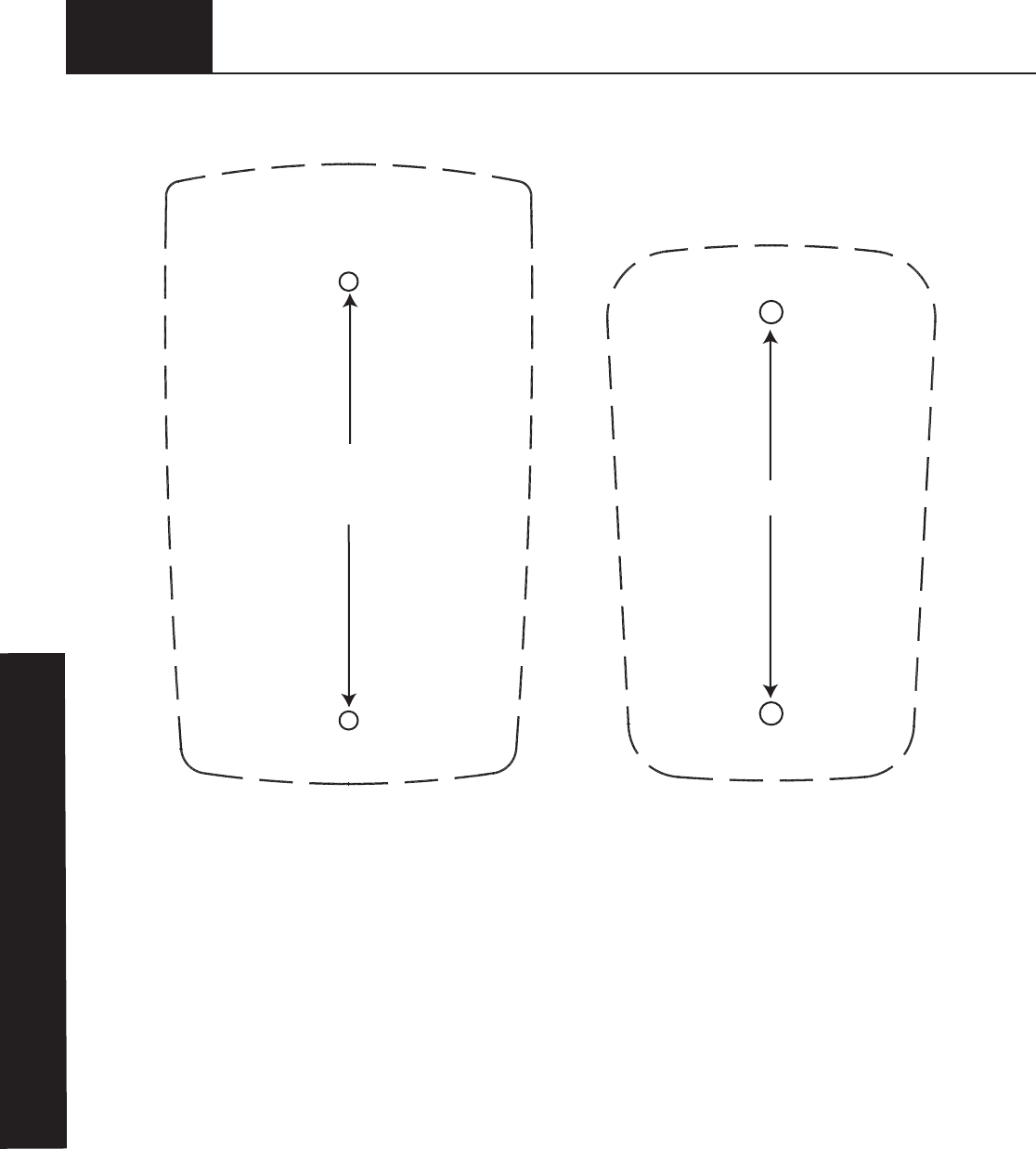
Pre-drill 5/64” pilot hole
Pre-drill 3/32” pilot hole
Cut-Out Template to Aid Installation
Wall Station Template Keyless Entry Template
✁
DRILL TEMPLATE

FCC and IC Statement
FCC Regulatory Information:
This device complies with Part 15 of the FCC Rules. Operation is subject to the following two conditions: (1) this
device may not cause harmful interference, and (2) this device must accept any interference received, including
interference that may cause undesired operation.
IC Regulatory Information:
Operation is subject to the following two conditions: (1) this device may not cause interference, and (2) this device
must accept any interference, including interference that may cause undesired operation of the device.
NOTE: This equipment has been tested and found to comply with limits for a Class B digital device, pursuant to
Part 15 of FCC Rules. These limits are designed to provide reasonable protection against harmful interference in
a residential installation. This equipment generates, uses and can radiate radio frequency energy and, if not
installed and used in accordance with these instructions, may cause harmful interference to radio communication;
however, there is no guarantee that interference will not occur in a particular installation. If this equipment does
cause harmful interference to radio or television reception, which can be determined by turning equipment off and
on, user is encouraged to try to correct interference by one or more of the following measures: Reorient or
relocate receiving antenna. Increase separation between equipment and receiver. Connect equipment into an
outlet on a circuit different from that which receiver is connected. Consult your dealer or/and experienced radio/
television technician for help.
WARNING: Changes or modifications to this unit not expressly approved by party responsible for compliance
could void user’s authority to operate this equipment.
Patent Information
Models:
3790/3790-Z/3791/3791-Z
Covered under one or more of the following U.S. patents: D413,579; D466,141; D472,568; D472,910;
D473,573; D473,574; D474,215; D505,393; D517,580; 5,929,580; 6,078,249; 6,145,570; 6,164,014;
6,253,824; 6,263,947; 6,325,134; 6,326,751; 6,326,754; 6,401,792; 6,561,255; 6,561,256; 6,568,454;
6,588,156; 6,605,910; 6,667,591; 6,739,372; 6,845,804; 6,851,465; 6,873,127; 6,880,609; 6,903,650;
7,053,571; 7,061,197; 7,075,256; 7,109,677; 7,123,128; 7,143,804; 7,173,389; 7,173,514; 7,173,516;
7,183,732; 7,190,266; 7,193,502; 7,207,142; 7,211,975. other U.S. and foreign patents pending