Wayne Dalton 0001715 TORQUE MASTER i-DRIVE PRO User Manual INSTALLATION GUIDE 2
Wayne Dalton Corporation TORQUE MASTER i-DRIVE PRO INSTALLATION GUIDE 2
Contents
- 1. INSTALLATION GUIDE 1
- 2. INSTALLATION GUIDE 2
- 3. INSTALLATION GUIDE 3
- 4. INSTALLATION GUIDE 4
INSTALLATION GUIDE 2

5015 B.U. Bowman Drive Buford, GA 30518 USA Voice: 770-831-8048 Fax: 770-831-8598
Certification Test Report
908.42 MHz Low Power Communication Device Transceiver
372 MHz Discrete Receiver
FCC ID: KJ8-0001715
IC: 3540A-0001715
FCC Rule Part: 15.249
IC Radio Standards Specification: RSS-210
ACS Report Number: 07-0186 - 15C
Manufacturer: Wayne-Dalton Corporation
Model: 3790-Z
Installation Guide
Section2
2Please Do Not Return This Product To The Store. Call Us Directly! Our Trained Technicians Will Answer Your Questions and/or Ship Any Parts You May Need.
You can reach us Toll Free at 1-888-827-3667 for Consumer Assistance or online at www.wayne-dalton.com
R3 End Bracket Removal
To remove end brackets, start with the right
hand end bracket and remove the lower lag
screw and carriage bolt.
Repeat for left hand end bracket.
CAUTION: THE WINDING SHAFT MAY
ROTATE WHEN REMOVING THE END
BRACKET AND GEAR.
Tools Needed:
Power Drill
7/16” Socket
Driver
1/2” Wrench
Step Ladder
Center Bracket & Cable Drum
Removal
To remove the cable drum/center bracket,
follow the steps below:
a. Remove the two 1/4" lag screws from
the center bracket. slide center bracket
to the right side of the torque tube.
Lift the right side of the torque tube up
and slide the cable drum and center
bracket off the end of the torque tube.
discard the center bracket.
b. Drape the cable drum over the flagangle
by the counterbalance cable and re-align
the groove in the winding shaft with the
round notch in the flagangle.
Once aligned, lower the winding shaft
and torque tube onto the flagangle.
Repeat cable drum removal for left side.
After completing this step, continue with
Step R5 on page 5.
R4
a
b
1/4”
Lag Screws
Center
Bracket
Torque
Tube
Tools Needed:
Power Drill
7/16" Socket
Driver
Step Ladder
Cable Drum
No space between Ratchet
Pawl and Cable Drum
indicates engagement
Cable Drum
Ratchet Pawl
ENGAGED SIDE VIEW
No space between
Ratchet Pawl and
Cable Drum
ENGAGED UNDERNEATH VIEW
Space between Ratchet Pawl
and Cable Drum
non-indicates engagement
Cable Drum
Ratchet Pawl
DISENGAGED SIDE VIEW
No space between
Ratchet Pawl and
DISENGAGED UNDERNEATH VIEW
UPPER POSITIONLOWER POSITION
LOWER POSITION SIDE VIEW
UPPER POSITION SIDE VIEW
Ratchet Pawl in Lower Position
Ratchet Pawl in Upper Position
Use these Illustration, in conjunction with the Instructions on the other side of
this label.
WARNING
WARNING
Rachet Bracket is under
Rachet Bracket is under
EXTREME SPRING
EXTREME SPRING
TENSION
TENSION.
To avoid possible severe or
To avoid possible severe or
fatal injury,
fatal injury,
DO NOT
DO NOT
remove
remove
fasteners from ratchet bracket
fasteners from ratchet bracket
until spring(s) are fully
until spring(s) are fully
wnwound.
wnwound.
To safely unwind spring(s)
To safely unwind spring(s)
read
read
and follow the directions in the
and follow the directions in the
installation instructions/owners
installation instructions/owners
manual.
manual.
DO NOT REMOVE THIS TAG.
DO NOT REMOVE THIS TAG.
5/16” X 1-5/8”
Hex Head Lag
End Bracket
(Right Hand)
5/16”-18 Hex Nut
5/16” - 18 X 3/4”
Carriage Bolt
Winding Shaft
Cable
Drum
Groove
Round Notch
Flagangle
Splines
3
Please Do Not Return This Product To The Store. Call Us Directly! Our Trained Technicians Will Answer Your Questions and/or Ship Any Parts You May Need.
You can reach us Toll Free at 1-888-827-3667 for Consumer Assistance or online at www.wayne-dalton.com
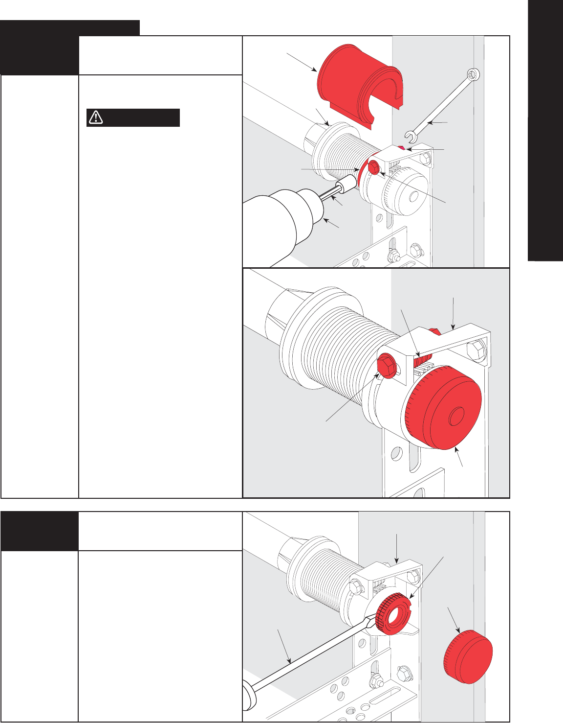
R1 Retro-Fit Installation
Spring Tension Removal
Counterbalance spring tension must be
relieved before removing any hardware.
A POWERFUL SPRING RELEASING ITS
ENERGY SUDDENLY CAN CAUSE SEVERE,
EVEN FATAL INJURY.
NOTE: Warning tag removed for illustration
clarity.
Place door in the fully closed position and
remove drum wraps from cable drums (if
installed).
Using a 7/16" wrench, loosen lock nut on
the back of the end bracket. Using a power
drill (high torque/gear reduced to 1300 RPM
preferred), with a 7/16" socket driver,
unwind the right hand winding bolt counter
clockwise until the counter cover shows “0”
(zero). If the door has two springs, repeat
this process for the left hand side.
NOTE: A door with only one spring will not
have a counter assembly on the left hand
side.
NOTE: Spring(s) is/are fully unwound when
counterbalance cables have no tension.
CAUTION: DO NOT USE AN IMPACT GUN
TO UNWIND THE SPRINGS!
NOTE: It is recommended that cable drums
and end bracket assemblies get updated to
current designs for optimal performance.
current end brackets are made of metal
instead of plastic, and counter cover and
worm gears are made of grey plastic, instead
of black and white plastic. If new parts are
required, contact Wayne-Dalton customer
service.
Tools Needed:
Flat Tip
Screwdriver
Step Ladder
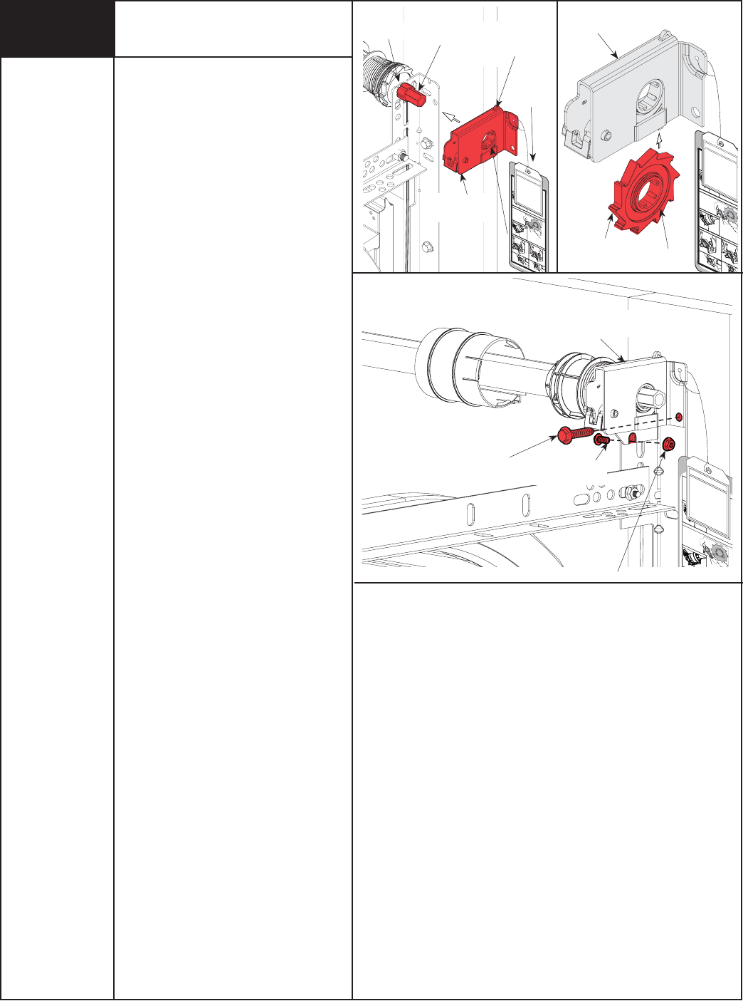
R2 Right Hand Counter Removal
IMPORTANT! RIGHT AND LEFT HAND IS
ALWAYS DETERMINED FROM INSIDE THE
GARAGE LOOKING OUT.
Remove the counter cover. Slide a flat tip
screwdriver between the end bracket and
the counter gear.
Gently pull the counter gear away from the
end bracket. If the door has two springs,
repeat this process for the opposite side.
7/16”
Wrench
Lock Nut
Power
Drill
Counter
Balance
Cable
Drum
Wrap
End Brackets
(Metal)
Counter
Cover
Worm
Gear
Counter
Gear
Flat Tip
Screwdriver
End Brackets
(Metal)
Counter
Cover
WARNING
Winding
Bolt
Winding
Bolt
Tools Needed:
7/16" Wrench
Power Drill
7/16"
Socket Driver
Step Ladder
Cable
Drum
7/16”
Socket Driver
Retro-Fit TorqueMaster®
RETRO-FIT TORQUEMASTER
®
PLUS
4Please Do Not Return This Product To The Store. Call Us Directly! Our Trained Technicians Will Answer Your Questions and/or Ship Any Parts You May Need.
You can reach us Toll Free at 1-888-827-3667 for Consumer Assistance or online at www.wayne-dalton.com
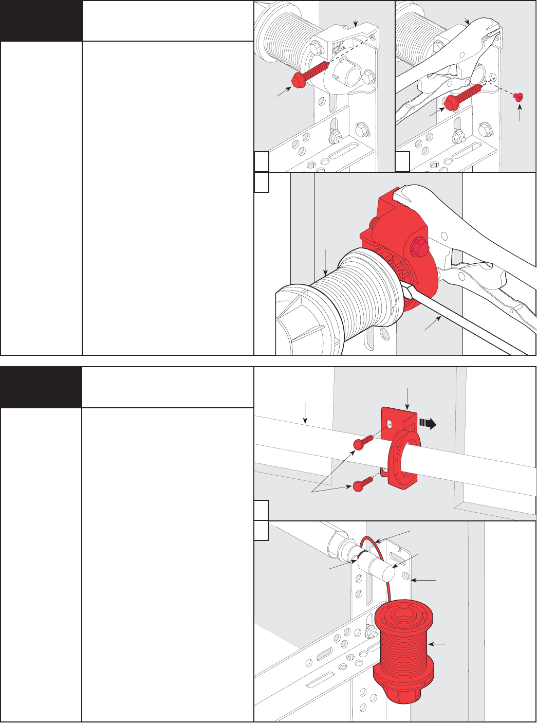
R3 End Bracket Removal
To remove the end brackets, follow the
steps below starting with the right hand
end bracket first:
a. Remove the upper lag screw from the
end bracket.
b. Attach a pair of locking pliers to the
upper portion of the end bracket and
hold the end bracket steady while
removing the lower lag screw.
If present, remove and save the #10
phillips head screw.
c. Holding the end bracket with the locking
pliers, carefully pry the end bracket from
the cable drum with a flat tip
screwdriver.
Repeat for left hand end bracket.
CAUTION: THE WINDING SHAFT MAY
ROTATE WHEN REMOVING THE END
BRACKET AND GEAR.
Center Bracket & Cable Drum
Removal
To remove the cable drum/center bracket,
follow the steps below:
a. Remove the two 1/4" lag screws from
the center bracket. Slide center bracket
to the right side of the torque tube.
Lift the right side of the torque tube up
and slide the cable drum and center
bracket off the end of the torque tube.
Discard the center bracket.
b. Drape the cable drum over the flagangle
by the counterbalance cable and re-align
the groove in the winding shaft with the
round notch in the flagangle.
Once aligned, lower the winding shaft
and torque tube onto the flagangle.
Repeat cable drum removal for left side.
After completing this step, continue with
Step R5 on page 5.
R4
Upper
Lag Screw
Lower
Lag Screw #10 Phillips
Head
Screw
Flat Tip
Screwdriver
a b
c
a
b
1/4”
Lag Screws
Center
Bracket
Torque
Tube
Winding
Shaft
Round Notch
in Flagangle
Cable
Drum
Cable
Drum
Tools Needed:
Locking Pliers
Phillips Head
Screwdriver
Flat Tip
Screwdriver
Power Drill
7/16” Socket
Driver
Step Ladder
Tools Needed:
Power Drill
7/16" Socket
Driver
Step Ladder
End
Bracket
Locking
Pliers
Flagangle
Counterbalance
Cable
5
Please Do Not Return This Product To The Store. Call Us Directly! Our Trained Technicians Will Answer Your Questions and/or Ship Any Parts You May Need.
You can reach us Toll Free at 1-888-827-3667 for Consumer Assistance or online at www.wayne-dalton.com
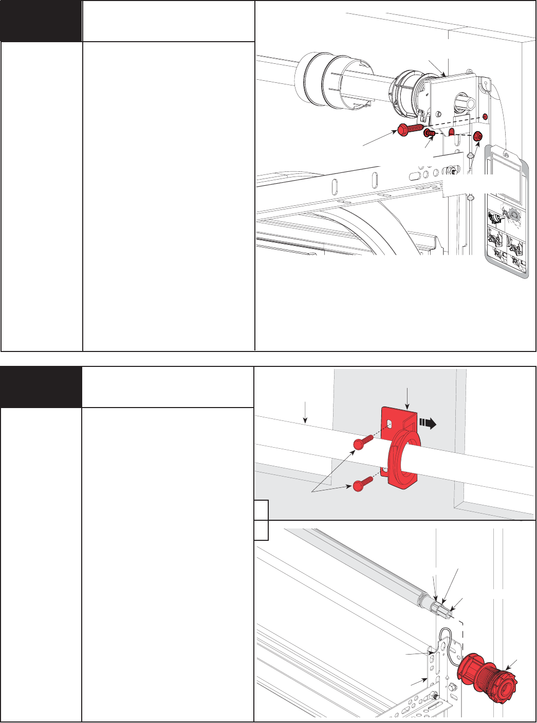
If installing an idrive® opener on an installed
9100 door, the top bracket and roller
location will have to be adjusted for the
opener to work properly.
Loosen the (2) 1/4”-20 nuts from the top
bracket slide.
Remove the (4) 1/4”-14 x 5/8" self-tapping
screws from the top bracket.
Raise the top bracket to align the bottom
slots with the second set of holes in the
end cap.
Re-attach top bracket to the end cap with
the (4) 1/4”-14 x 5/8" self-tapping screws.
Re-align the top roller in the horizontal track
by moving the top bracket slide out to force
the door section against the weather seal.
Tighten (2) 1/4”-20 Nuts.
Repeat for the opposite side.
NOTE: The 9100 doors have a painted steel face, foam insulation and
white paper backing. If your door does not match this description you may
skip this step.
CAUTION: TO AVOID THE TOP PANEL FROM FALLING, COMPLETE RE-
INSTALLATION ON ONE SIDE BEFORE BEGINNING THE OTHER.
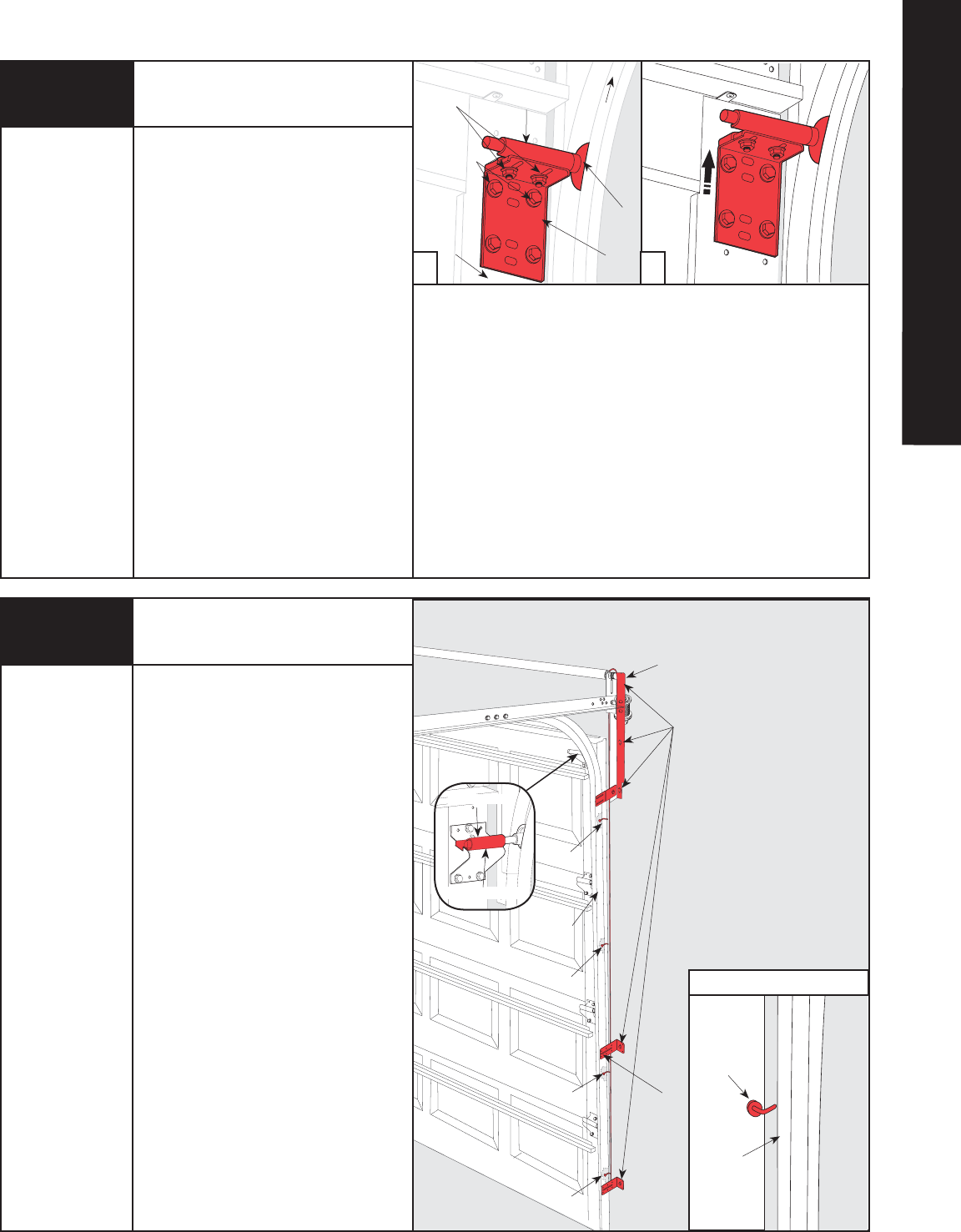
R5 9100 Top Bracket
Re-Install (If Necessary)
NOTE: The door must be in the fully closed
position.
If installing an idrive® opener on an
8000/8100/8200 door, the top roller location
and track height will have to be modified for
the opener to work properly. Perform the
following steps:
NOTE: The bottom edge of the track needs to
be spaced 1” above the floor. If the track is
already spaced off the floor 1”, skip this step.
Fasten a nail in the door jamb, between the
door and the track at the ends of each
section. Bend the nail over each section to
hold them in place.
Remove the lag screws from the flagangle and
each jamb bracket. Using a 7/16" socket
driver, loosen the flange nut on the Top
bracket slide. Place a mark 1" up from one of
the tops of one of the jamb brackets. Raise
the track up and align the jamb bracket with
this line. With the track relocated, re-attach
the flagangle, end bracket, and jamb brackets
to the header and/or door jamb. Make certain
to maintain spacing between edge of door and
vertical track.
NOTE: Pilot drill all lag screw locations.
8000/8100/8200 Track
Vertical Track Height Adjustment
(If Required)
a b
Top
Bracket
Slide
1/4” - 20
Carriage Bolts
and Nuts
1/4” - 14 x 5/8”
Self-Tapping
Screws
Top
Roller
Horizontal
Track
Top
Bracket
Remove
Lag Screws
Jamb
Bracket
Flagangle
Nail
Nail
Nail
Nail
Nail Placement
End Cap
Track
Track
Nail bent
over door
section
Tools Needed:
Power Drill
7/16" Socket
Driver
Step Ladder
Tools Needed:
Power Drill
7/16" Socket
Drive
Pencil
Tape Measure
Step Ladder
Flange Nut
Top Bracket Slide
(Door Section)
R6
RETRO-FIT TORQUEMASTER
®
6Please Do Not Return This Product To The Store. Call Us Directly! Our Trained Technicians Will Answer Your Questions and/or Ship Any Parts You May Need.
You can reach us Toll Free at 1-888-827-3667 for Consumer Assistance or online at www.wayne-dalton.com
1"
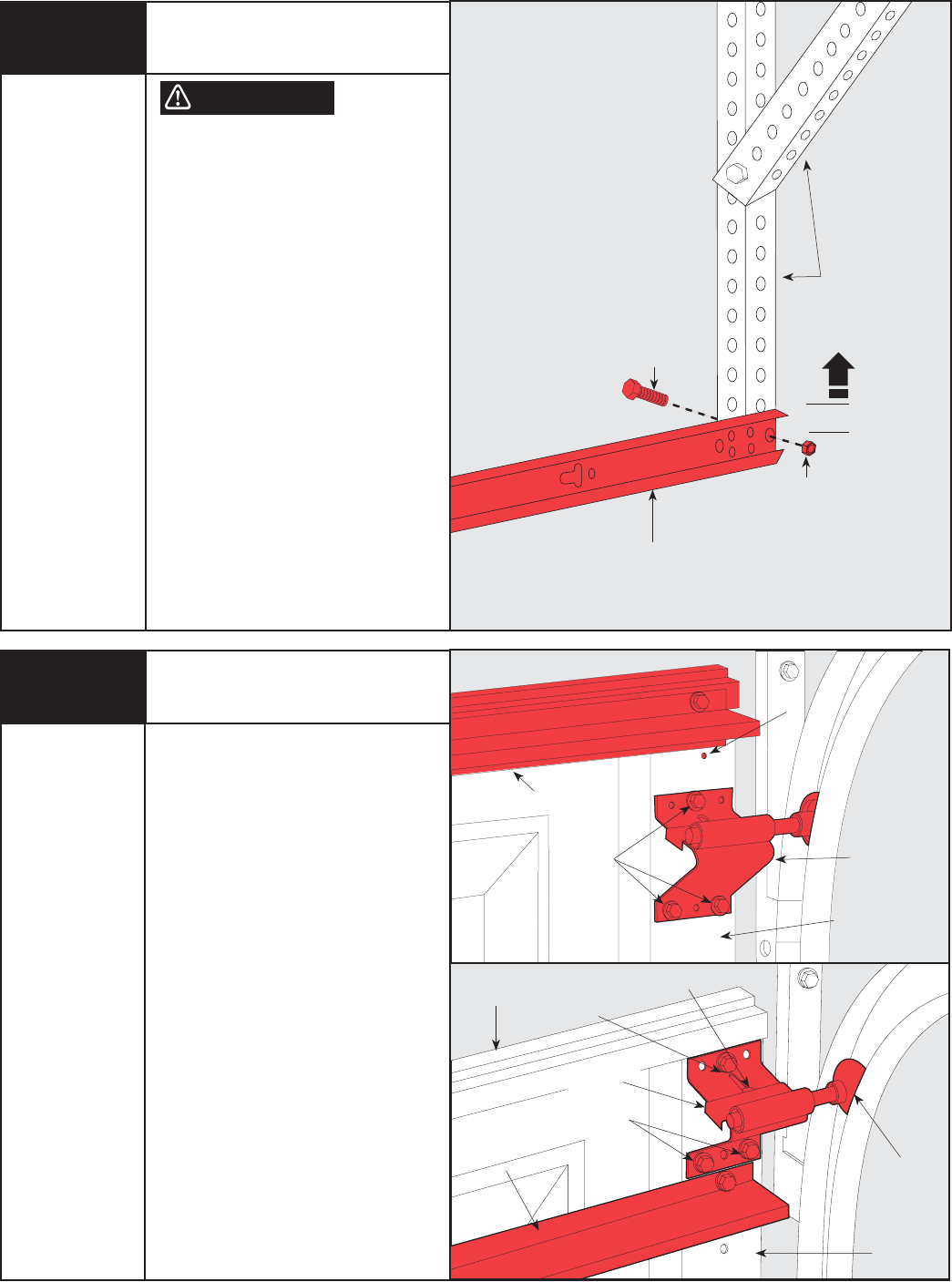
FAILURE TO RE-ATTACH HORIZONTAL
TRACKS TO THE SUPPORT BEFORE
OPENING DOOR CAN CAUSE DOOR
TO FALL FROM OVERHEAD POSITION,
POSSIBLY CAUSING SEVERE OR FATAL
INJURY.
NOTE: Door must be in the fully closed
position.
If the vertical track was raised then the
horizontal track will need to be adjusted.
Remove bolt securing back of horizontal
track to the perforated angle and reposition
horizontal track UP 1” (25mm) from it’s
original position.
Re-attach the horizontal track to the
perforated angle with the same
bolt and nut.
Assemble bolt and nut from the direction
shown so bolt will extend inside of track.
8000/8100/8200 Track
Horizontal Track Height
Adjustment (If Required)
Remove the (3) self-tapping screws from
the top bracket.
Align the top hole of the top bracket with
the #2 hole in the end cap and re-attach the
top bracket to the end cap with the same
three self-tapping screws. It may be
necessary to relocate the top strut (if
installed) to correctly place the top bracket
in its new location.
Re-align the top roller in the track by
moving top bracket slide out until door
section is straight up and down. Tighten the
flange nut.
Repeat for opposite side.
8000/8100/8200 Track
Top Roller Adjustment
(If Necessary)
Perforated
Angles
Top
Strut
Self-tapping
Screws
#2 Hole
Top
Bracket
End Cap
#2 Hole with
Self-tapping
Screw
Self-tapping
Screws
Top
Strut
End Cap
Tools Needed:
Level
1/2” Wrench
Step Ladder
Tools Needed:
Power Drill
7/16" Socket
Driver
Step Ladder
Flange Nut
Door Section
Top Roller
Horizontal
Track
Bolt
Nut
Top Bracket
Slide
WARNING
R7
R8
7
Please Do Not Return This Product To The Store. Call Us Directly! Our Trained Technicians Will Answer Your Questions and/or Ship Any Parts You May Need.
You can reach us Toll Free at 1-888-827-3667 for Consumer Assistance or online at www.wayne-dalton.com
S1 S2 S3 S4
Learn Delete
Controls
S3S
4Delete
n
trols
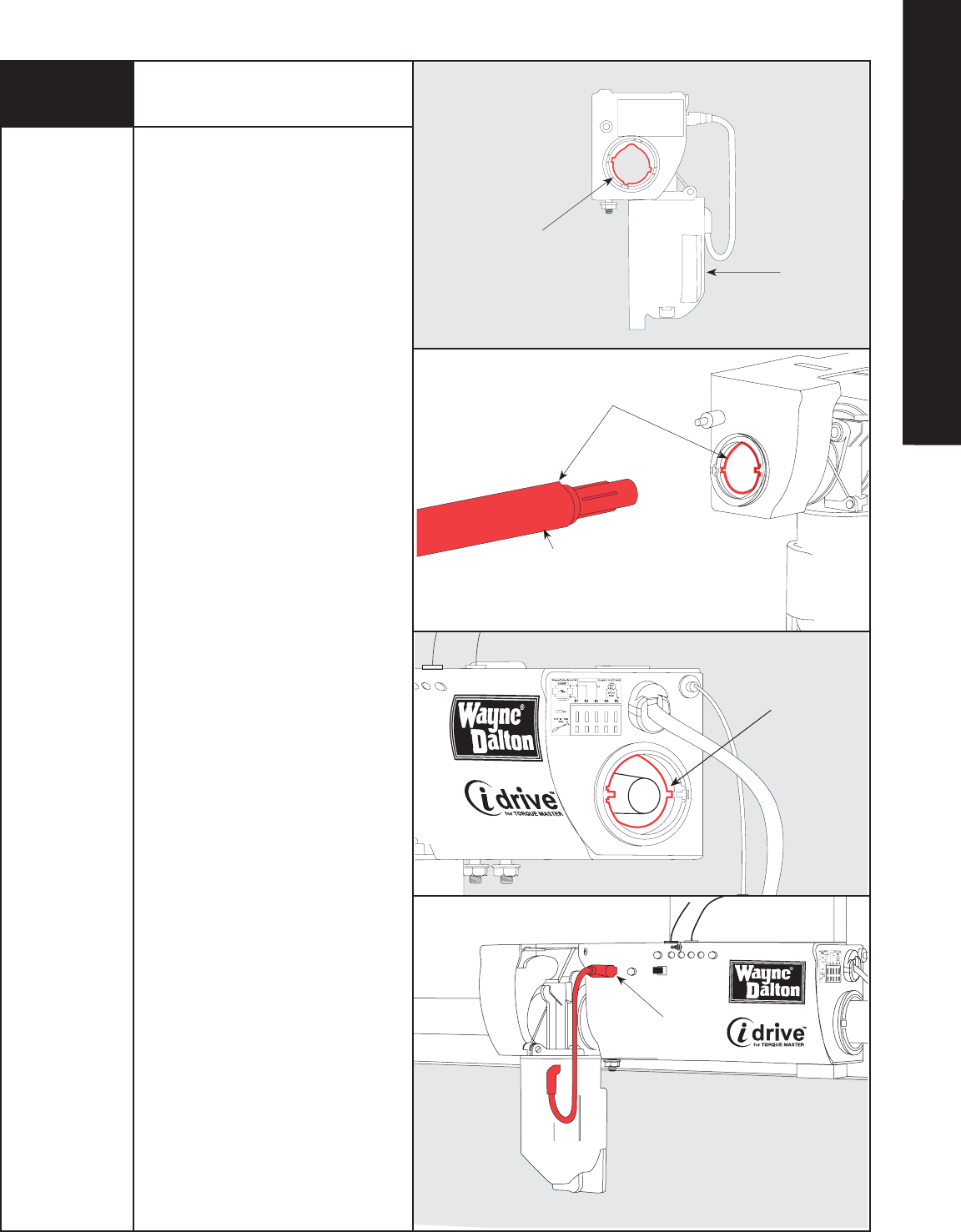
IMPORTANT! RIGHT AND LEFT HAND IS
ALWAYS DETERMINED FROM INSIDE THE
GARAGE LOOKING OUT.
NOTE: Older versions of the torque tube
have a label applied on the right side that
the opener will not slide over. Check the
location of the label on the torque tube. If
your torque tube has the label located on
the right side, document the information on
the label, then remove it completely using
an adhesive remover or mineral spirits. If
your torque tube has the label located on
the left side, proceed with the following
instructions.
Lay the torque tube on the floor (inside
garage) in front of the door with the labeled
end to the left.
Look into the opener’s left side to ensure
the left hand bearing and the internal (black)
sleeve are aligned with the torque tube
profile.
IMPORTANT! HOLD OPENER BY THE MAIN
BODY. DO NOT HOLD BY THE MOTOR.
Once aligned, slide the opener onto the
right hand end of the torque tube. As the
right end of the torque tube enters the
internal (black) sleeve, rotate the opener
back and forth slightly to help aid alignment.
Continue sliding the opener onto the torque
tube. Align the right hand bearing with the
torque tube and slide the opener completely
onto the torque tube until the torque tube
exits the opener right hand bearing.
NOTE: Do not force the opener onto the
torque tube if misalignment occurs.
Continue sliding the opener to the center
of the torque tube.
Plug the motor power cord into the opener.
After completing this step, continue with
Step 2 on page 8 for Torquemaster® Plus;
Step 2 on page 11 for Torquemaster®.
Tools Needed:
None
Idrive® for Torquemaster®
Installation
Assembling Opener
Left Hand Side
Torque Tube and
Bearing profiles
aligned
Right Hand End
of Torque Tube
Right Hand Side
Torque Tube and
Bearing profiles
aligned
Align Torque Tube profile
with Bearing profile
Plug-in Motor
Power Cord
Motor
1
RETRO-FIT INSTALLATIONS
8Please Do Not Return This Product To The Store. Call Us Directly! Our Trained Technicians Will Answer Your Questions and/or Ship Any Parts You May Need.
You can reach us Toll Free at 1-888-827-3667 for Consumer Assistance or online at www.wayne-dalton.com
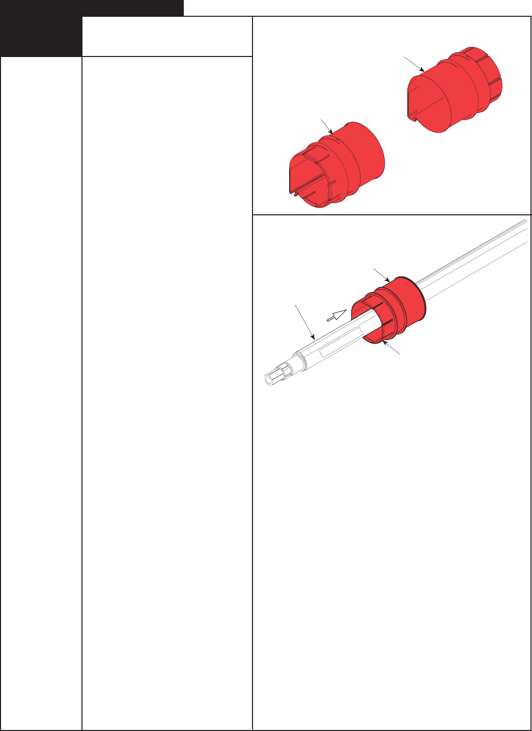
NOTE: If you have a Torquemaster®
counterbalance, skip this step and continue
with Step 2 on page 11. If you have a
Torquemaster® Plus counterbalance system,
complete Steps 2-4 on pages 8, 9 and 10.
IMPORTANT! RIGHT AND LEFT HAND IS
ALWAYS DETERMINED FROM INSIDE THE
GARAGE LOOKING OUT.
Drum wraps are identifi ed as right and left
hand.
Slide the left hand drum wrap over the
left side of the TorqueMaster® spring tube
assembly with the tabs facing left. Continue
sliding the left hand drum wrap towards the
center of the TorqueMaster® spring tube
assembly.
Slide the right hand drum wrap over the
right side of the TorqueMaster® spring
tube assembly with the tabs facing right.
Continue sliding the right hand drum wrap
towards the center of the TorqueMaster®
TorqueMaster® Spring Tube
Assembly
Tabs
Left Hand Drum Wrap
Left Hand Drum Wrap
Right Hand Drum Wrap
Drum Wraps
2
Tools Needed:
None
TorqueMaster® Plus Installation
9
Please Do Not Return This Product To The Store. Call Us Directly! Our Trained Technicians Will Answer Your Questions and/or Ship Any Parts You May Need.
You can reach us Toll Free at 1-888-827-3667 for Consumer Assistance or online at www.wayne-dalton.com
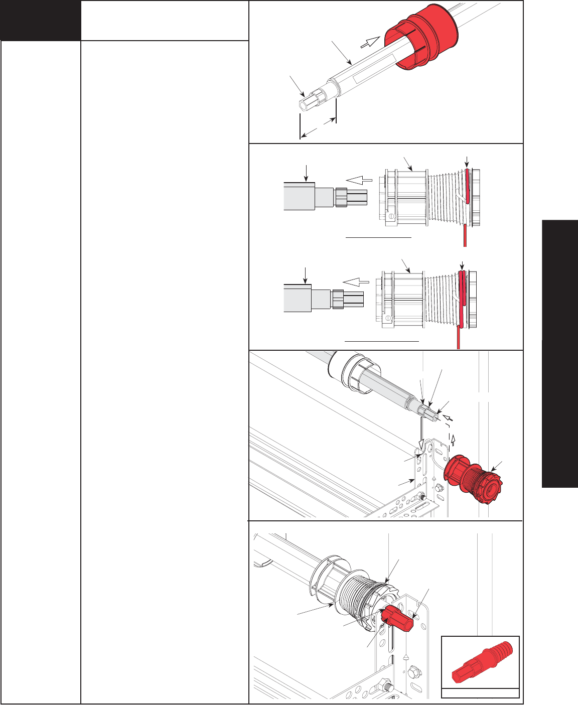
IMPORTANT! RIGHT AND LEFT HAND IS
ALWAYS DETERMINED FROM INSIDE THE
GARAGE LOOKING OUT.
Shake the TorqueMaster® spring tube
assembly gently to extend the winding shafts
out about 5" on each side. For single spring
applications, there will be no left hand spring
in the TorqueMaster® spring tube assembly.
Lift the TorqueMaster® spring tube assembly
and rest it on the top of the flagangles.
NOTE: Cable drums are marked right and
left hand. Cable drums and TorqueMaster®
spring tube assembly are cam shaped to fit
together only one way.
Pre-wrap the Torquemaster® Plus cable
drum with the counter balance cable either
1/2 or 1-1/2 wraps (see illustrations).
To install the cable drum, slide the correct
cable drum over the winding shaft until the
cable drum seats against the TorqueMaster®
spring tube assembly.
The winding shaft must extend past the
cable drum far enough to expose the splines
and the groove. Align the winding shaft
groove with the round notch in the flagangle.
For double spring applications, repeat for
opposite side.
For single spring applications, insert
the loose winding shaft into the left hand
cable drum prior to sliding the cable drum
over the TorqueMaster® spring tube
assembly.
NOTE: On single spring applications, take
care in handling the loose winding shaft (left
side) so that it does not slide back into the
TorqueMaster® spring tube assembly.
Winding Shaft
Right Drum
5”
Winding Shaft
Cable
Drum
Groove
Round Notch
Flagangle
Splines
Counterbalance Cable
Cable Drum
Winding Shaft
Splines
Groove
2Cable Drums
Loose Winding Shaft
Tools Needed:
Tape Measure
Step Ladder
TorqueMaster® Spring Tube
Assembly
TorqueMaster® Spring Tube
Assembly
3
Right Drum
TorqueMaster® Spring Tube
Assembly
1/2 Wrap Shown
1-1/2 Wrap Shown
Counterbalance Cable
Counterbalance Cable
RETRO-FIT INSTALLATIONS
10 Please Do Not Return This Product To The Store. Call Us Directly! Our Trained Technicians Will Answer Your Questions and/or Ship Any Parts You May Need.
You can reach us Toll Free at 1-888-827-3667 for Consumer Assistance or online at www.wayne-dalton.com
Cable Drum
No space betwe
e
Pawl and Ca
b
indicates eng
a
C
a
Ratchet Pawl
ENGAGED SIDE VIEW
No space between
Ratchet Pawl and
Cable Drum
ENGAGED UNDERNEATH VIEW
Space between
R
and Cable
non-indicates e
Ratchet Pawl
DISENGAGED SIDE VIEW
No space between
Ratchet Pawl and
DISENGAGED UNDERNEATH VIEW
UPPER POSITIONLOWER POSITION
L
UPPER POSITION SIDE VIEW
Ratchet Pawl in Lower
P
Ratchet Pawl in Upper Position
Use these Illustration, in conjunction with the Instructions on the o
t
this label.
WARNING
WARNING
Rachet Bracket is under
Rachet Bracket is under
EXTREME SPRING
EXTREME SPRING
TENSION
TENSION.
To avoid possible severe or
To avoid possible severe or
fatal injury,
fatal injury,
DO NOT
DO NOT
remove
remove
fasteners from ratchet bracket
fasteners from ratchet bracket
until spring(s) are fully
until spring(s) are fully
wnwound.
wnwound.
To safely unwind spring(s)
To safely unwind spring(s)
read
read
and follow the directions in the
and follow the directions in the
installation instructions/owners
installation instructions/owners
manual.
manual.
DO NOT REMOVE THIS TAG.
DO NOT REMOVE THIS TAG.
Cable Drum
No space between Ratchet
Pawl and Cable Drum
indicates engagement
Cable Drum
Ratchet Pawl
ENGAGED SIDE VIEW
No space between
Ratchet Pawl and
Cable Drum
ENGAGED UNDERNEATH VIEW
Space between Ratchet Pawl
and Cable Drum
non-indicates engagement
Cable Drum
Ratchet Pawl
DISENGAGED SIDE VIEW
No space between
Ratchet Pawl and
DISENGAGED UNDERNEATH VIEW
UPPER POSITION LOWER POSITION
LOWER POSITION SI
DEVI
UPPER POSITION SIDE VIEW
Ratchet Pawl in Lower Position
Ratchet Pawl in Upper Position
Use these Illustration, in conjunction with the Instructions on the other side of
this label.
WARNING
WARNING
Rachet Bracket is under
Rachet Bracket is under
EXTREME SPRING
EXTREME SPRING
TENSION
TENSION.
To avoid possible severe or
To avoid possible severe or
fatal injury,
fatal injury,
DO NOT
DO NOT
remove
remove
fasteners from ratchet bracket
fasteners from ratchet bracket
until spring(s) are fully
until spring(s) are fully
wnwound.
wnwound.
To safely unwind spring(s)
To safely unwind spring(s)
read
read
and follow the directions in the
and follow the directions in the
installation instructions/owners
installation instructions/owners
manual.
manual.
DO NOT REMOVE THIS TAG.
DO NOT REMOVE THIS TAG.
IMPORTANT! WARNING TAGS MUST BE
SECURELY ATTACHED TO BOTH END
BRACKETS.
End brackets are right and left hand. You
can identify the right hand end bracket by
the disconnect cable guide hole in the top
of the bracket.
Attach TorqueMaster® Plus warning tags to
both end brackets prior to installing.
Beginning with either side, slide the end
bracket onto the winding shaft so that the
grooves in the ratchet wheel fit onto the
winding shaft splines.
Secure end bracket to the flag with (1)
5/16”-18 x 3/4” carriage bolt and hex nut
and then secure to the jamb with 5/16” x
1-5/8” hex head lag screw.
Repeat for other end bracket.
NOTE: No ratchet wheel is required on the
left hand side for single spring applications.
Only an end bracket is needed.
After completing this step, continue with
Step 5 on page 13.
Splines Winding
Shaft
Groove
Disconnect Cable
Guide Hole
Right End
Bracket
Warning Tag
Right End
Bracket
Ratchet Wheel
Teeth Pointing Upward
3End Brackets
No space between Ratch
e
Pawl and Cable Drum
indicates engagement
Cable Dru
m
Ratchet Pawl
ENGAGED SIDE VIEW
No space between
Ratchet Pawl and
Cable Drum
ENGAGED UNDERNEATH VIEW
C
able
Ratchet Pa
wl
DISENGAGED SIDE VIEW
N
DISENGAGED UNDERNEATH VIEW
Use these Illustration, in conjunction with the Instructions on the other si
d
this label.
WARNING
WARNING
Rachet Bracket is under
Rachet Bracket is under
EXTREME SPRING
EXTREME SPRING
TENSION
TENSION.
To avoid possible severe or
To avoid possible severe or
fatal injury,
fatal injury,
DO NOT
DO NOT
remove
remove
fasteners from ratchet bracket
fasteners from ratchet bracket
until spring(s) are fully
until spring(s) are fully
wnwound.
wnwound.
To safely unwind spring(s)
To safely unwind spring(s)
read
read
and follow the directions in the
and follow the directions in the
installation instructions/owners
installation instructions/owners
manual.
manual.
DO NOT REMOVE THIS TAG.
DO NOT REMOVE THIS TAG.
5/16” x 1-5/8”
Hex Head Lag
End Bracket
(Right Hand)
5/16”-18 Hex Nut
5/16” - 18 X 3/4”
Carriage Bolt
Tools Needed:
Power Drill
7/16” Socket
Driver
1/2” Wrench
Step Ladder
4