Wayne Fueling Systems VISTA RF ID Tag Reader User Manual 06206 10 FCC Vista
Wayne Fueling Systems LLC RF ID Tag Reader 06206 10 FCC Vista
Contents
- 1. user manual 1 of 2
- 2. user manual 2 of 2
- 3. user manual statement
user manual 2 of 2

47
March 2003 Part No. 920365 Rev B
5 OPERATOR MAINTENANCE
5.1 Preventive Maintenance
The safety precautions described in Section 1.3 apply to the following preventive maintenance procedures. A
correctly installed dispenser, given proper preventive maintenance attention, will seldom require emergency
service. Perform the following checks on a regular basis:
• Check the dispenser for internal and external leaks regularly. Check nozzles, swivels, hoses, filters, and
joints for leaks and wear. Have all defects repaired immediately.
• Do not abuse the hose by trying to stretch it to reach an automobile. This will cause early failure at the cou-
plings.
• Keep the dispenser clean at all times. Use only mild soap and water with a soft cloth. Do not use gasoline or
other petroleum-based products to clean the dispenser. Do not use abrasive cleaners on any part of the dis-
penser. All stainless steel surfaces require polishing with a non-abrasive silicone wax a minimum of three
times per year to maintain a bright finish and prevent corrosion. If it is necessary to just wipe off the dis-
penser, use a damp cloth. See Section 5.3 for additional information on cleaning and corrosion prevention.
NOTE: Do not spray the dispenser with water.
• Before removing the bezel, wipe off any water lying along the top edge of the dispenser so it will not run
inside when the bezel is removed.
• If the bezels must be removed during rainy weather, take care to prevent rain from getting inside the
dispenser.
• Test the tank for water regularly. Water in petroleum is not only a source of engine trouble but will also
cause damage to the dispenser.
• Check the nozzle boot switch operation. If this does not operate easily, too much force may be applied on
the switch mechanisms, causing premature failure.
• Periodically check and lubricate all key lock cylinders and locking mechanisms.
5.2 Strainer/Filter
A dirty strainer screen and/or fuel filter will slow down the delivery of product. See Figure 2-3 for location. If
the underground installation is new, it may be necessary to replace the filter and clean the strainer screen two or
three times during the first few days of operation to remove installation debris and pipe sealant. After this, filter
replacement and strainer cleaning should be performed periodically.
WARNING
Before removing the filter and strainer turn the power to the dispenser and submersible pump(s) off and
close the emergency shut-off valves on the dispenser being serviced. Failure to do so may result in a haz-
ardous condition that can result in serious injury. Loosen strainer cap or spin-on filter slightly and allow
gasoline to drain into a plastic container until pressure is relieved. Return product to the appropriate under-
ground tank.

48
Part No. 920365 Rev B March 2003
5.1 Preventive Maintenance, continued
• The fuel filter is removed by unscrewing it (the same way an oil filter is removed from a car
engine). Place a container under the filter to catch the product and sediment. To install the new
filter, first apply a film of oil to the gasket and hand turn until gasket contacts base, then tighten
one half turn. Open the emergency shut-off valve(s), turn the electrical power ON and check for
leaks.
• Remove the strainer for cleaning by unscrewing the filter (or cap) and then pulling out the
strainer. Place a container under the filter or cap to catch the petroleum and sediment. Wash the
screen in gasoline and dislodge lint and other foreign particles with compressed air. Install the
clean strainer and a new filter. Open the emergency shut-off valve(s), turn the electrical power
ON and check for leaks.
NOTE: Replacement fuel filters must be UL recognized.
5.3 Cleaning And Corrosion Prevention Instructions
To properly care for your dispenser:
Step 1 Wash the dispenser frequently with a non-abrasive cloth and warm water mixed with a mild
household cleaner (such as dishwashing liquid). The dispenser should then be wiped down
with a clean damp cloth. Do not use a hose to rinse off the dispenser.
NOTE: Do not direct pressurized water (even from a garden hose) at the dispenser.
Under no circumstances should power washers be used to clean the
dispensers. This can force water into the electronic head and cause damage
to the electronic components in the dispenser rendering it inoperative.
Do not use all-purpose cleaners on the surfaces of the dispenser. They may
scratch the clear plastic, as well as break down the corrosion resistance of
painted and stainless steel surfaces.
NOTE: Do not use gasoline or other petroleum-based products to clean the
dispenser.
Step 2 Exposure to contaminants can cause a discoloration of the stainless steel panels (doors,
column covers, etc.). If the discoloration persists after washing (as instructed above), the
use of an abrasive powder cleaner is very effective in restoring the original shine.
Step 3 Two cleaners in particular are very effective and practical to use: Zud Heavy Duty Cleaner
and Bar Keepers Friend. They can both be found in most hardware/grocery stores. Follow
the manufacturers’ instructions for use and always rub in the direction of the brush finish to
prevent scratching the stainless steel.
Periodic waxing of the dispenser surfaces is essential to maintain the original finish and inhibit corro-
sion. Stainless steel surfaces should be polished with a non-abrasive silicone wax. Painted surfaces
should be waxed with an automotive wax or polish. We recommend that these surfaces be waxed or
polished at least three times a year.

49
March 2003 Part No. 920365 Rev B
5.4 Vapor Recovery
All hoses, nozzles, breakaways, etc., must be CARB certified for use on Wayne vapor recovery dis-
pensers.
5.4.1 Wayne Vac
See Section 2.15 and the Compliance Testing and Preventative Maintenance manual, p/n 917947.
5.4.2 Balance
Tears and slits and the balance nozzle vapor bellows will cause the vapor system to be in
non-compliance. Replace or repair the nozzles as necessary.
The bellows face-plate (where nozzle seals on vehicle fuel tank) must make a good seal when
inserted into the fuel tank. Damaged or warped faces are not acceptable and will cause the system to
be in non-compliance. Replace or repair as necessary.
Wire clamps at top of the bellows may have critical placement to requirement to maintain compli-
ance. If clamp is loose or broken, it must be replaced or repaired according to the nozzle manufac-
turer instructions.
To ensure on-going compliance of the balance system, once per year checks of the pressure drop and
tightness of the system are recommended. These test are discussed in Section 2.14.
5.5 Meter Maintenance Issue
It is recommended that Wayne Fuel Meters be periodically checked for acceptable accuracy based
on NCWM Handbook 44 under the General Code, G-UR.4 Maintenance Requirements and Liquid
Measuring Device Code, Section 3.30.
If adjustment need to be made, one would follow the prescribed procedure in the service manuals for
the respective equipment. All adjustments shall be made in accordance with G-UR.4 Maintenance
Requirements of Handbook 44.

50
Part No. 920365 Rev B March 2003
51
March 2003 Part No. 920365 Rev B
APPENDIX A
CAT SELF-TEST PROCEDURE
The following are instructions for testing the CAT (Customer Activated Terminal) on the dispenser.
1. CAT SYSTEM SELF-TEST
The following paragraphs provide instructions for testing and setting the address of the CAT. During the
self-test, the system is designed to pause 25 seconds for a response to self-test prompts. When the 25 second
time limit expires, the system automatically advances to either the next self-test or returns to the on-line
mode.
1.1. ENTERING SELF-TEST MODE
Step 1 Power down the CAT.
Step 2 Power up the CAT while holding down any key on the keypad until the alternating message below
appears on the display.
Step 3 Press the indicated key or press ENTER to continue to the next screen prompt.
1.2. SOFTWARE REVISION LEVEL AND DATA LINK ADDRESS
Step 1 Continue holding the key down until the “REV” message below appears on the display, then
release. Once the system displays the “REV” message, the module has successfully entered the
self-test mode.
The top row of information in the “REV” message display represents the module software revision.
The bottom row is the current terminal address for the data link. Data link addresses are assigned to
the module using the same number as the fueling point.
Step 2 If the CAT’s data link address is correct, press the ENTER key. To change the address, enter the
correct address number on the keypad and press ENTER (if the CAT is equipped with a DES
keypad, the keypad revision will be displayed).
CONTRAST ADJUST
PRESS NEXT TO EXIT
YES = DARKER
NO = LIGHTER
REV XXX MM/DD/YY
ADDRESS = YY
52
Part No. 920365 Rev B March 2003
1.2 CAT SELF TEST, continued
Step 3 Verify that the Keypad revision and BCB revision levels are displayed on the screen. The
BCB revision displayed will be the software revision of the BCB board or the QCAT board
whichever applies.
Step 4 Press ENTER to continue.
1.3. CONFIGURE CARD READER
When the system displays the prompt below, proceed as follows:
Answering YES to the prompt causes the screen to display the prompt below
or
press NO on the keypad and the system automatically proceeds to the "Offline msg" prompt.
To answer the “Track 1 or 3" prompt, perform the following steps:
Step 1 Press 1 on the keypad.
Step 2 Press the ENTER key and the following prompt will be displayed.
KEYPAD REV __
BCB REV __
*CONFIGURE CARD READER
(Y/N)
TRACK 1 OR 3
(1/3)
53
March 2003 Part No. 920365 Rev B
1.3 Configure Card Reader, continued
Step 3 Answer NO to the above prompt.
Step 4 Answer the following prompts as they appear:
Answering YES to the above prompt will begin the display, printer and card reader self test as discussed on
the following pages.
Answering NO to the above prompt will display the Exit Prompt shown below.
Answer YES to the above prompt to exit and return the CAT to normal operation.
Answer NO to the above prompt to return to the beginning of the Self Test mode.
Offline msg: Out
of Service (Y/N)
Long Receipts?
(Y/N)
Fixed Length Scanner?
(Y/N)
Self Test?
(Y/N)
Exit Test Mode?
(Y/N)
54
Part No. 920365 Rev B March 2003
1.4. DISPLAY SELF-TEST
A series of actions appear on the screen for the display self-test. Two rows of black squares followed
by numbers and letters scroll from right to left across the screen during the display self-test.
1.5. PRINTER SELF-TEST
The message shown below appears continuously on the display screen during the printer self-test.
The printer self-test performs the following actions in sequence:
1. Advance the paper one half inch.
2. Print CAT information (ROM version, processor type, etc.)
3. Print five rows of characters followed by five more rows of slashes (\ and /).
4. Advance the paper one inch and cut the paper.
Once the paper is cut, the system automatically activates the card reader self-test.
1.6. CARD READER SELF-TEST
Any type of valid credit card can be used for the card reader test. The card reader self-test begins
with the screen prompt shown below.
Step 1 Insert the card.
Once the credit card is inserted into the card reader, the CAT computer reads data from the
card.
Step 2 Remove the credit card in one smooth continuous motion when the above prompt appears
on the display screen.
PRINTING TEST
INSERT CARD
PULL IT OUT

55
March 2003 Part No. 920365 Rev B
1.6. CARD READER SELF-TEST, continued
A series of digits appear on lines 1 and 2 of the display screen. This information is the card data.
Step 3 Press the NEXT key and continue to the keypad self-test.
If either of the following prompts appear on the display screen, “TRACK READ ERROR” or
“CARD READ ERROR”, the credit card is invalid. Depending on the type of invalid credit card, one
or two rows of digits may appear on the display screen. To complete the card reader self-test, select a
different credit card and repeat procedure. If the error message continues to be displayed, the card
reader may need replacing.
1.7. KEYPAD SELF-TEST
Testing the CAT keypad requires the operator to select keys on the keypad and verify the information
on the display screen. Refer to the Keypad Test table on the following page.
Complete the following steps to test the keypad.
Step 1 Press a key listed under the column heading Native Mode Key.
Step 2 Verify the two digit number on the display screen with the number listed under the column
heading Keypad Coordinate.
The screen does not display a two digit number when the NEXT key is pressed. This key
remains functional during the keypad self-test.
Step 3 Repeat Steps 1 and 2 until all of the keys are tested.
Step 4 Press the NEXT key to proceed to the memory self-test.
TRACK READ ERROR
CARD READ ERROR
56
Part No. 920365 Rev B March 2003
1.7 KEYPAD SELF-TEST, continued
1.8. SYSTEM MEMORY SELF-TEST
A successful memory self-test will display the message below.
An unsuccessful memory self-test will display one of the following: “BIT 0" through “BIT 7".
A BIT error message is an indication of a defective board in the CAT system. An example of a
BIT error message that may appear on the display screen is shown below.
KEYPAD TEST
Native Mode Key Keypad Coordinate
CLEAR 00
7 01
4 02
1 03
0 10
8 11
5 12
2 13
ENTER 20
9 21
6 22
3 23
CANCEL 30
NO 32
YES 33
NEXT Proceed to memory test.
MEMORY OK
BIT 4

57
March 2003 Part No. 920365 Rev B
1.9. EXIT SELF-TEST MODE
Once the system successfully completes the memory self-test, the exit prompt shown below appears
on the screen.
Complete one of the following steps:
Press the YES key to exit the self-test mode,
or
Press the NO key to begin the self-test mode again.
EXIT TEST MODE
(Y/N)

58
Part No. 920365 Rev B March 2003

59
March 2003 Part No. 920365 Rev B
APPENDIX B
SECTION RESERVED FOR FUTURE USE

60
Part No. 920365 Rev B March 2003

61
March 2003 Part No. 920365 Rev B
APPENDIX C ENGINEERING DRAWINGS
3/Vista models have different base layouts (footprints) than previous Vista models, however,
the installation wiring diagrams are the same.
Dispenser drawings appear in this section in the following order:
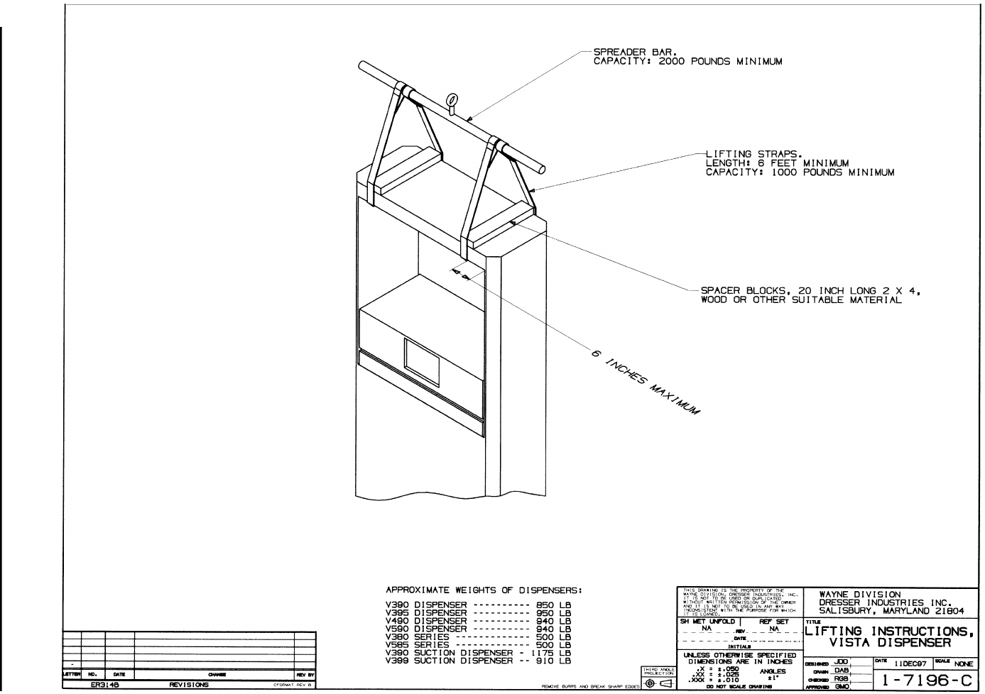
Model Number Type Drawing Number Description
1-7196-C Lifting Instructions
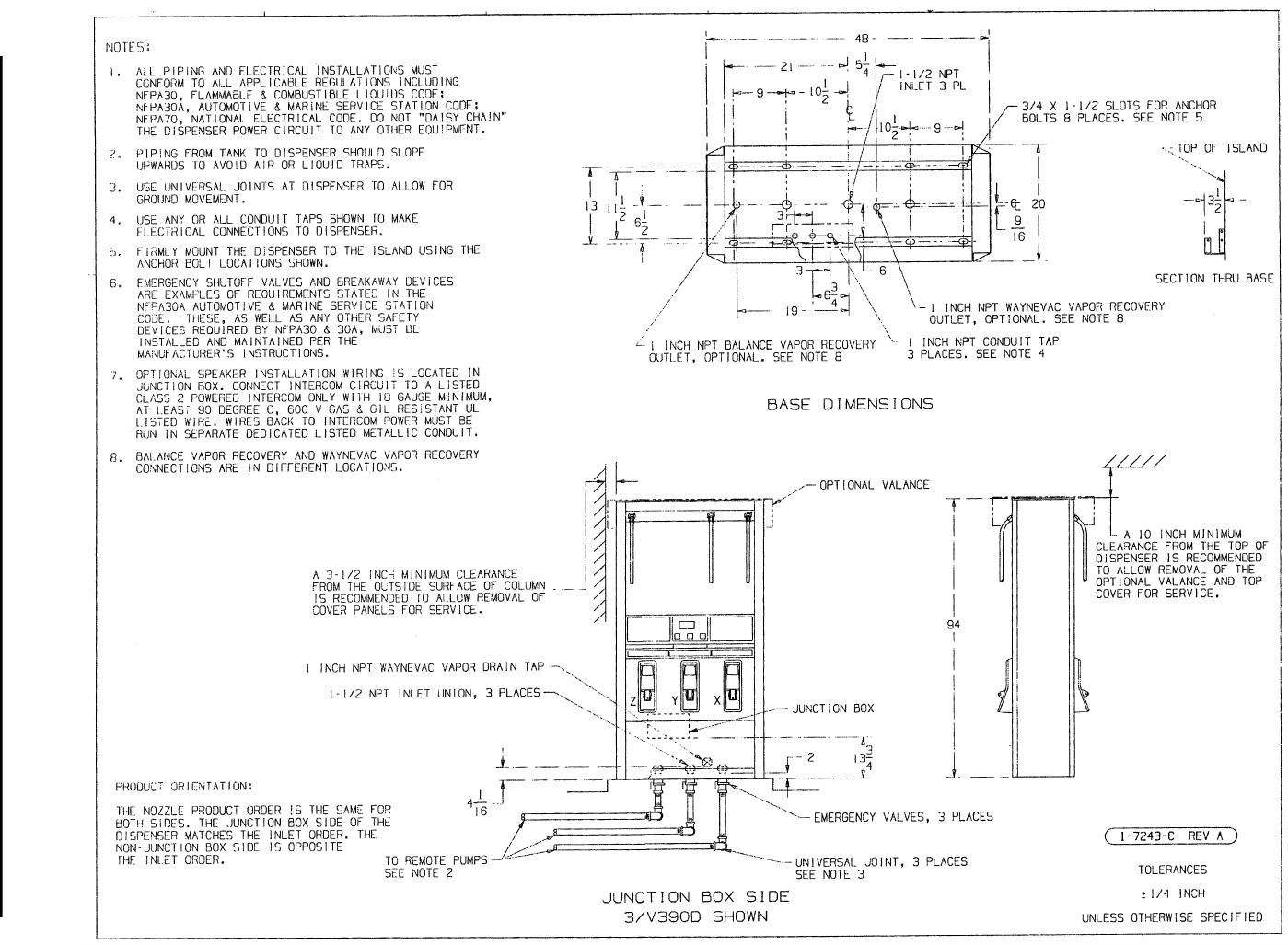
3/V390D, 3/V390D/U Remote 1-7243-C Footprint
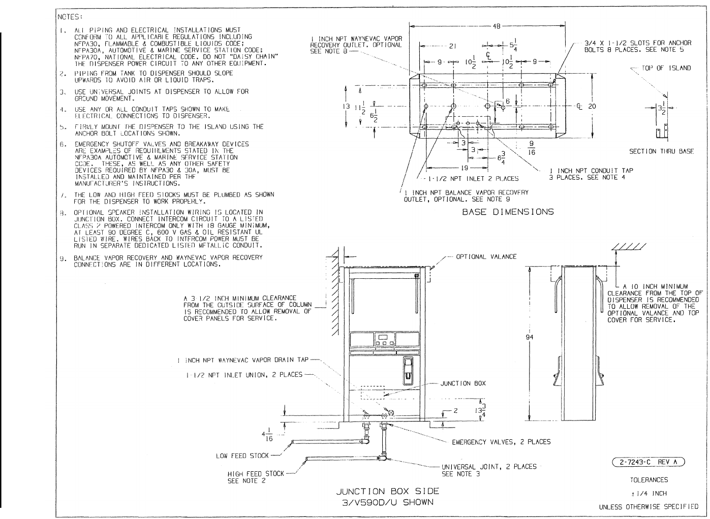
3/V590D/U, 3/V595D/U Remote 2-7243-C Footprint
3/V399D Remote 3-7243-C Footprint
3/V490D/U Remote 4-7243-C Footprint
3/V387D Remote 5-7243-C Footprint
3/V388D, 3/V389D Remote 6-7243-C Footprint
3/V580D, 3/V585D Remote 7-7243-C Footprint
3/V595D, except D/U Remote 8-7243-C Footprint
3/V490D, except D/U Remote 9-7243-C Footprint
3/V590D, except D/U Remote 10-7243-C Footprint
3/V591D Remote 11-7243-C Footprint
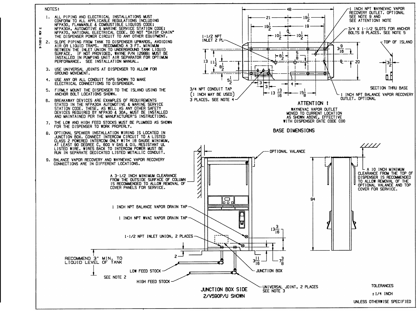
3/V590P/U, 3/V595P/U Suction 9-7193-C Footprint
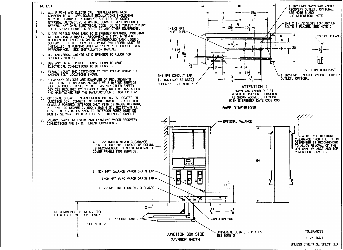
3/V390P, 3/V390P/U Suction 10-7193-C Footprint
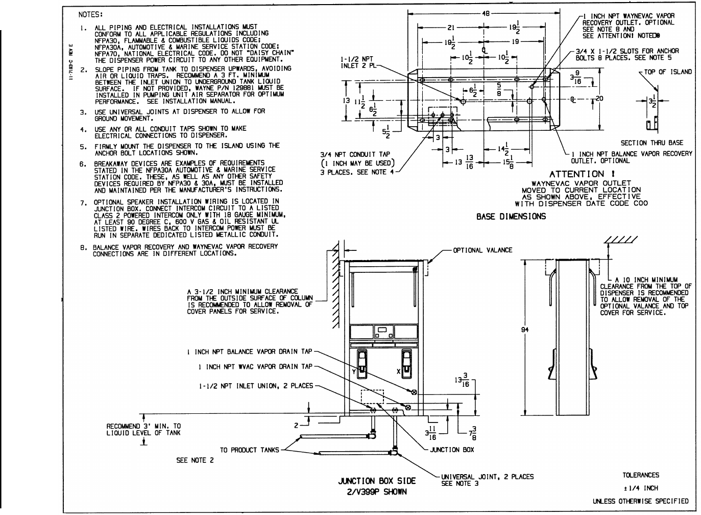
3/V399P Suction 11-7193-C Footprint
3/V591P, 3/V595P, except P/U Suction 12-7193-C Footprint
3/V387P Suction 13-7193-C Footprint
3/V389P Suction 14-7193-C Footprint
3/V580P, 3/V585P Suction 15-7193-C Footprint
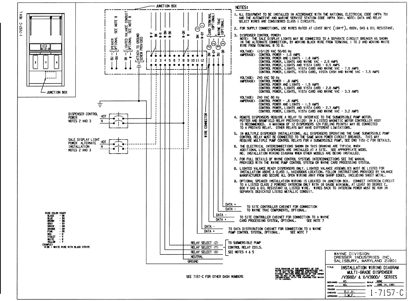
3/V390D, except D/U Remote 1-7157-C Wiring Diagram
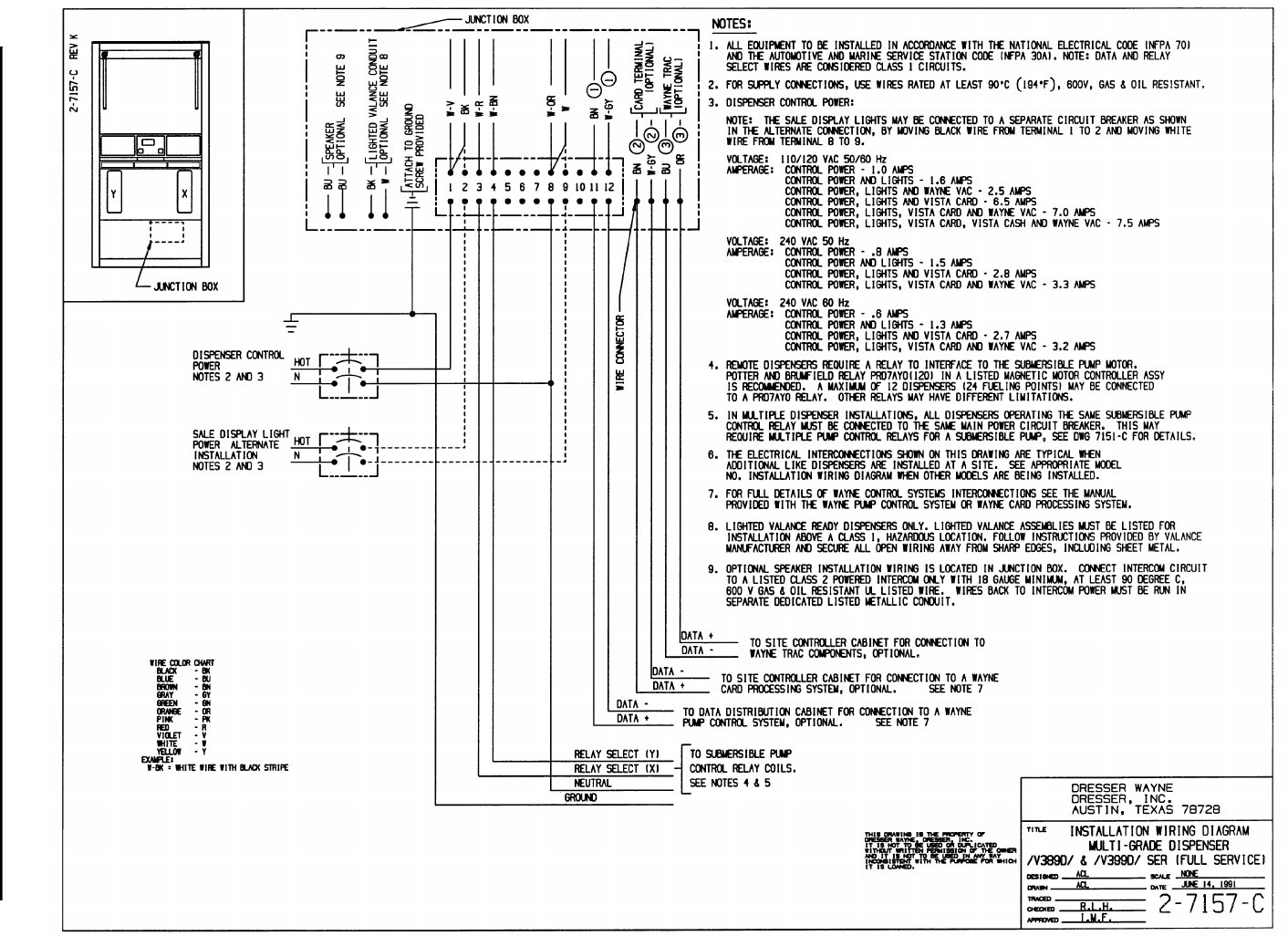
3/V389D, 3/V399D Remote 2-7157-C Wiring Diagram
3/V490D Remote 3-7157-C Wiring Diagram
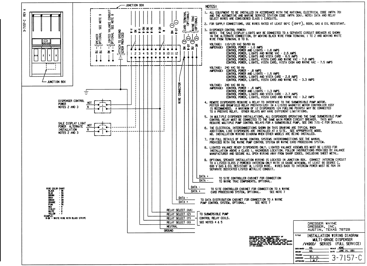
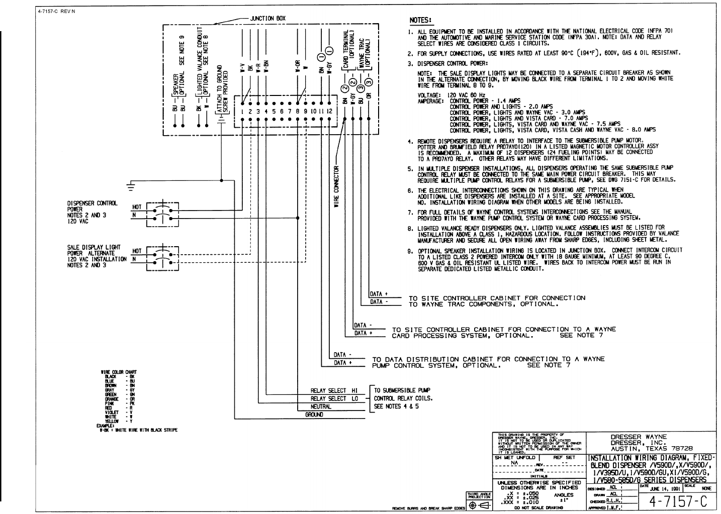
Blenders, except 591D, 595D Remote 4-7157-C Wiring Diagram
3/V387D Remote 5-7157-C Wiring Diagram
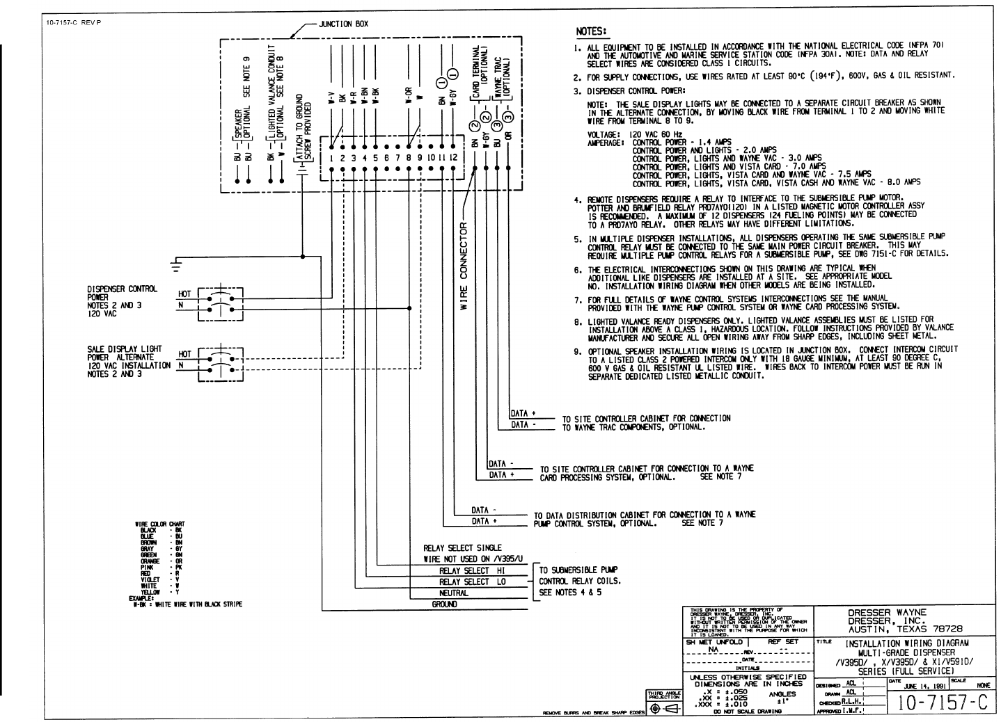
3/V591D, 3/V595D, except D/U Remote 10-7157-C Wiring Diagram
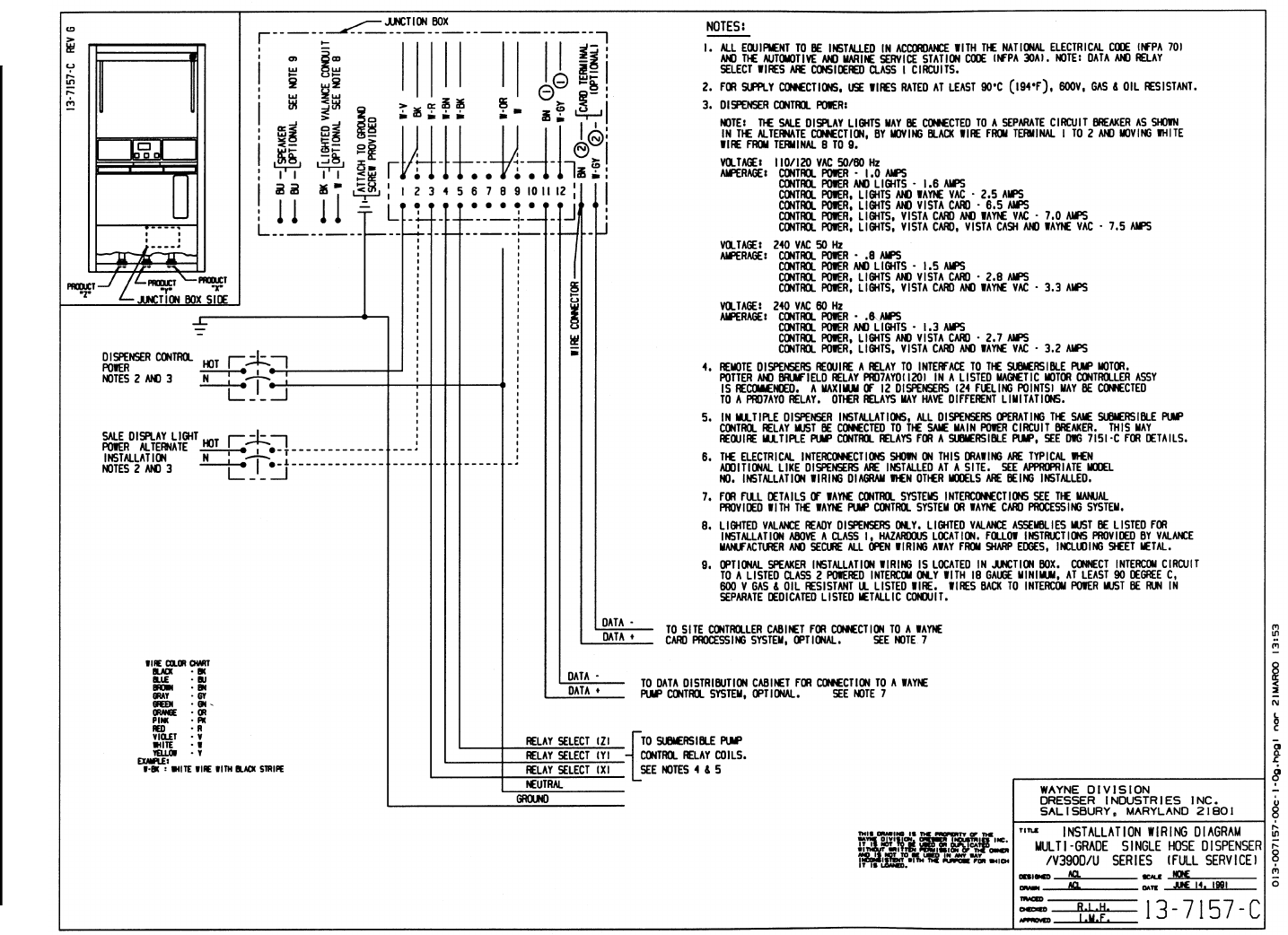
3/V390D/U Remote 13-7157-C Wiring Diagram
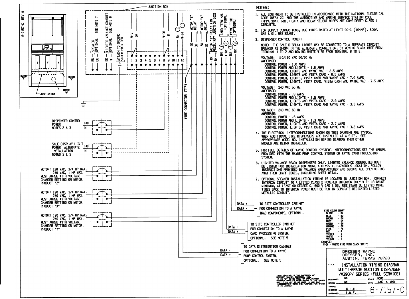
3/V390P Suction 6-7157-C Wiring Diagram
3/V389P, 3/V399P Suction 9-7157-C Wiring Diagram
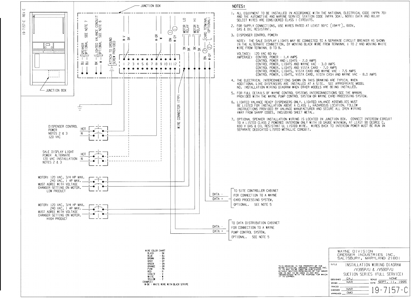
3/V590P/U, 3/V595P/U Suction 19-7157-C Wiring Diagram
-7151-C Typ Disp Site Wiring
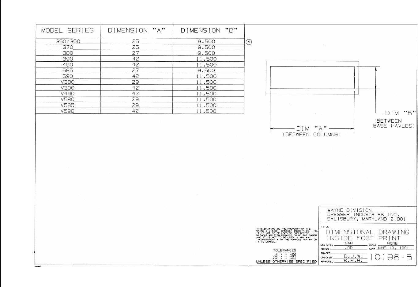
10196-B Dimensional Drawing
62
March 2003 Part No. 920365 Rev B
Figure C-1. 1-7196-C Vista Field Lifting Instruction
63
March 2003 Part No. 920365 Rev B
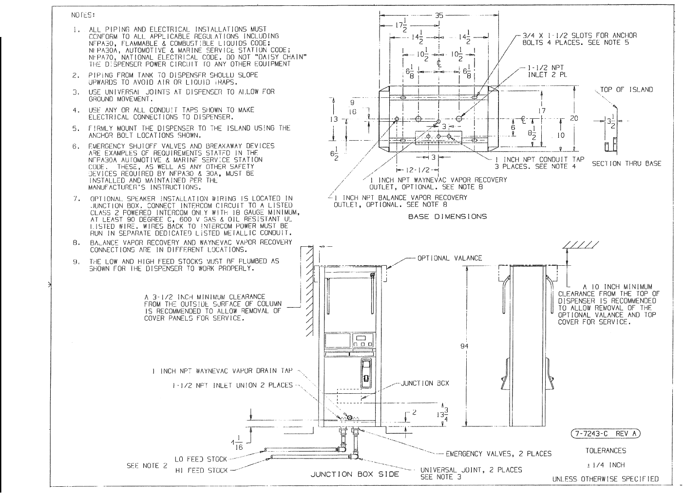
Figure C-2. 1-7243-C Installation Instructions - 3/V390D and 3/V390D/U (Remote)
64
March 2003 Part No. 920365 Rev B
Figure C-3. 2-7243-C Installation Instructions - 3/V590D/U and 3/V595D/U (Remote)
65
March 2003 Part No. 920365 Rev B
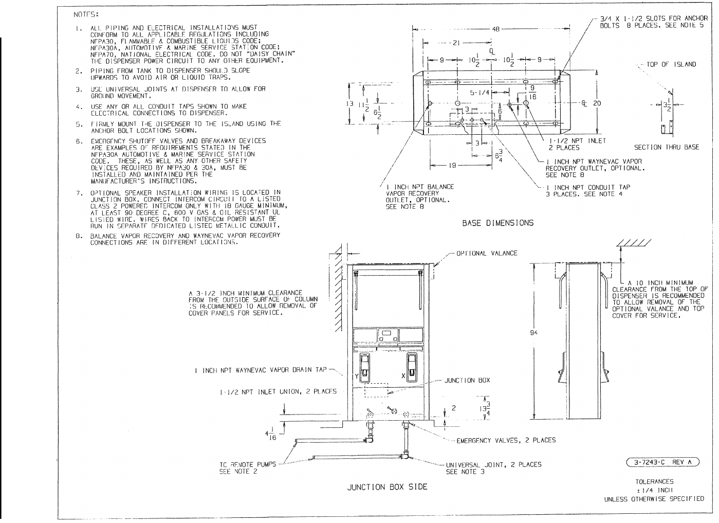
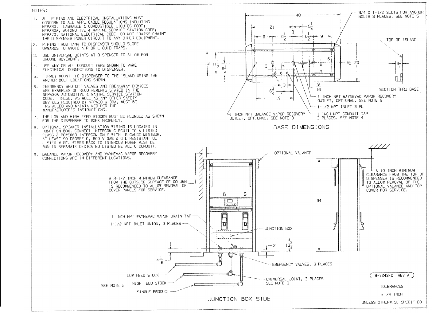
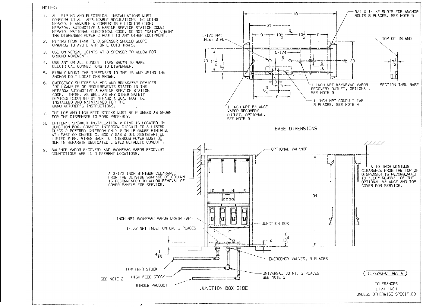
Figure C-4. 3-7243-C Installation Instructions - 3/V399D (Remote)
66
March 2003 Part No. 920365 Rev B
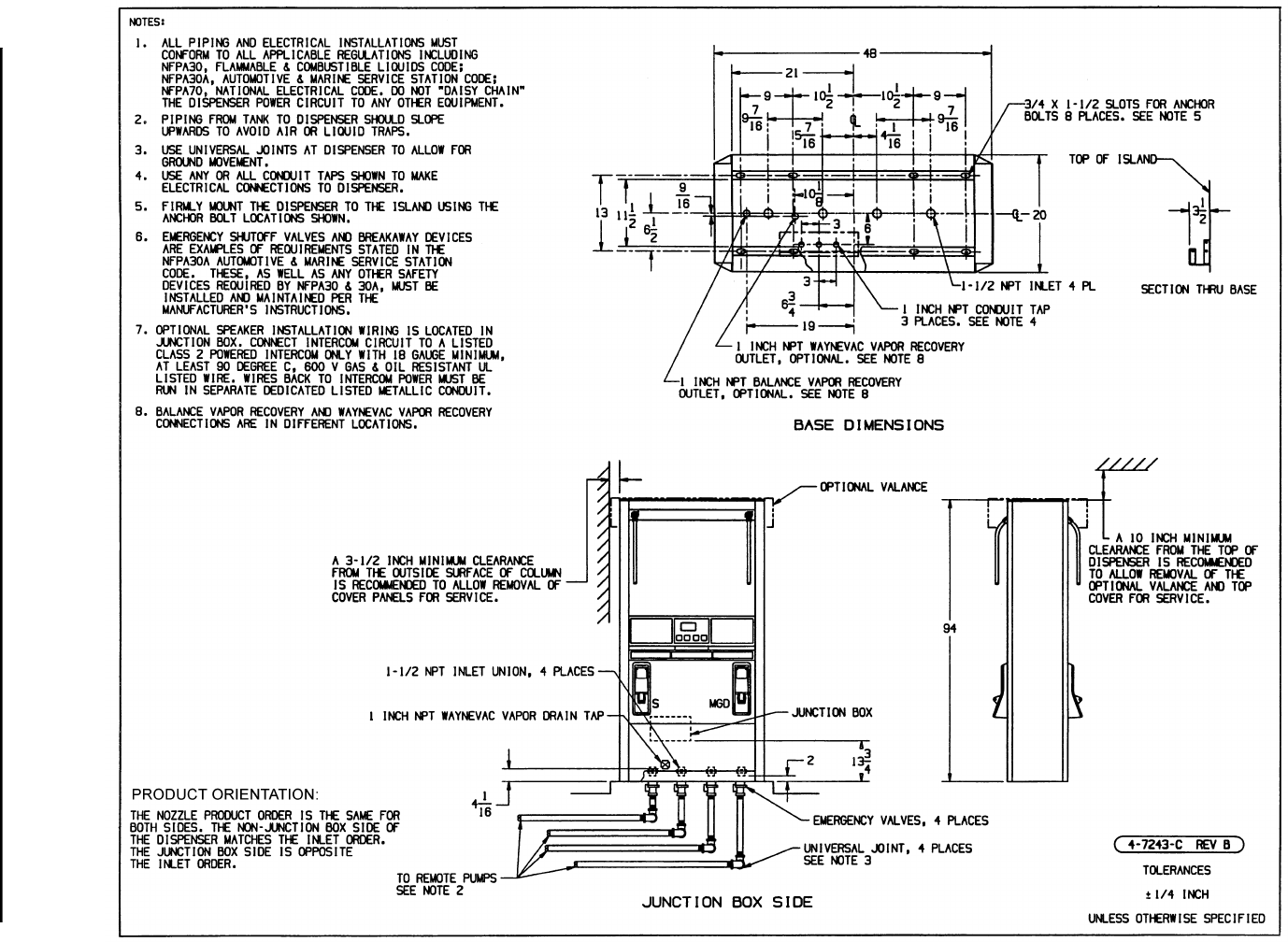
Figure C-5. 4-7243-C Installation Instructions - 3/V490D/U (Remote)
67
March 2003 Part No. 920365 Rev B
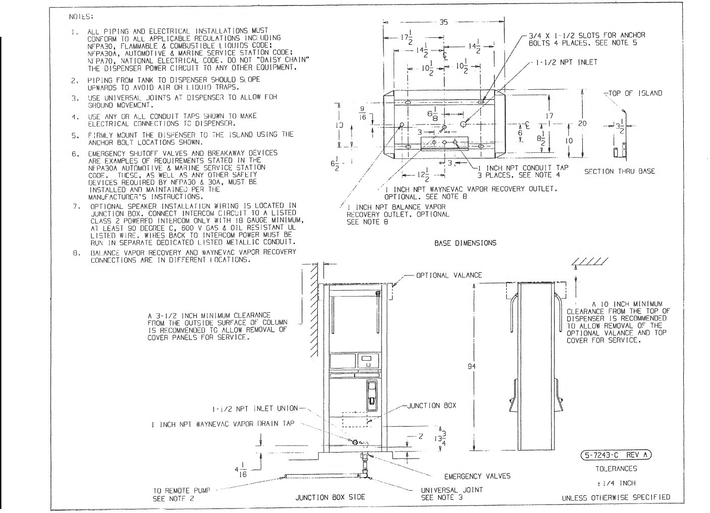
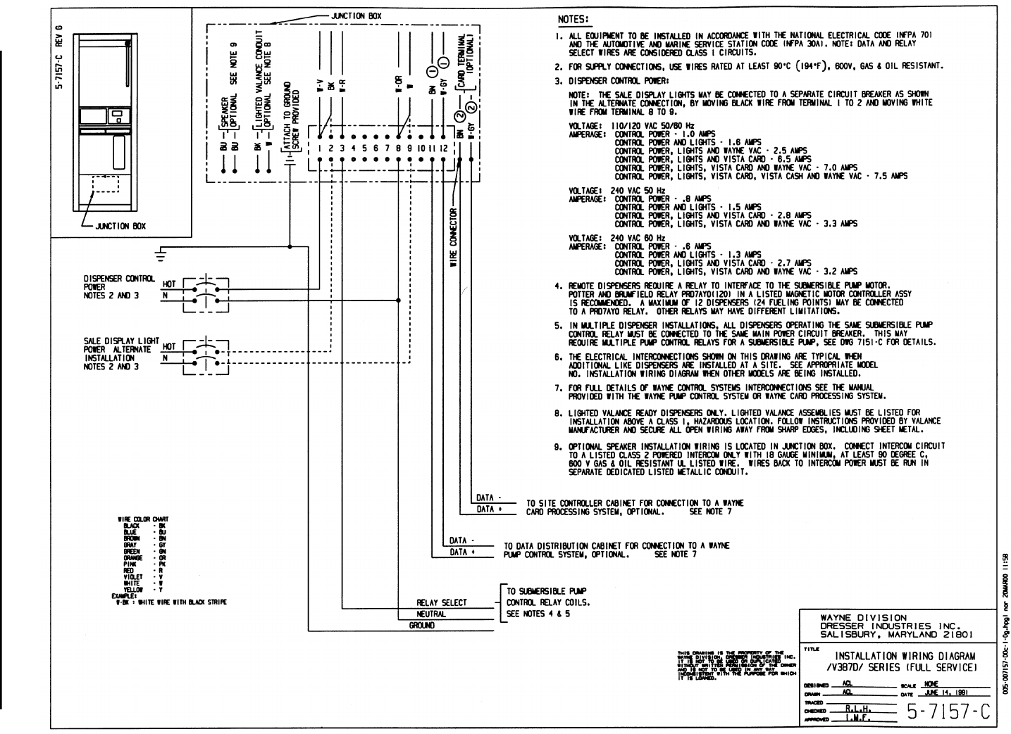
Figure C-6. 5-7243-C Installation Instructions - 3/V387D (Remote)
68
March 2003 Part No. 920365 Rev B
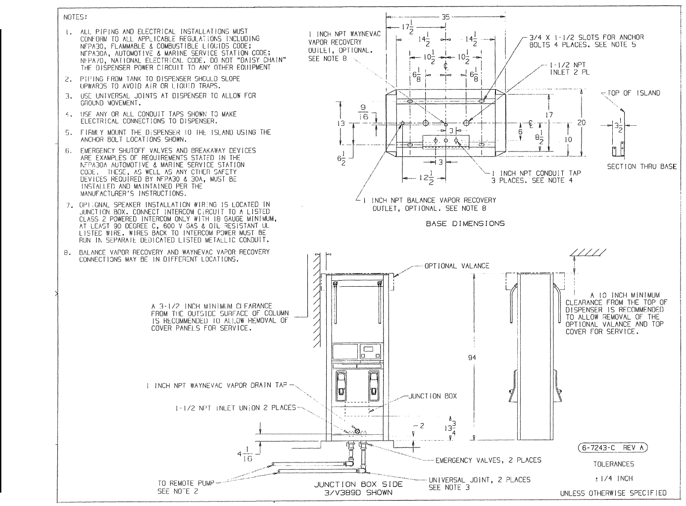
Figure C-7. 6-7243-C Installation Instructions - 3/V388D and 3/V389D (Remote)
69
March 2003 Part No. 920365 Rev B
Figure C-8. 7-7243-C Installation Instructions - 3/V580D and 3/V585D (Remote)
70
March 2003 Part No. 920365 Rev B
Figure C-9. 8-7243-C Installation Instructions - 3/V595D (Remote) - Except 3/V595D/U See 2-7243-C
71
March 2003 Part No. 920365 Rev B
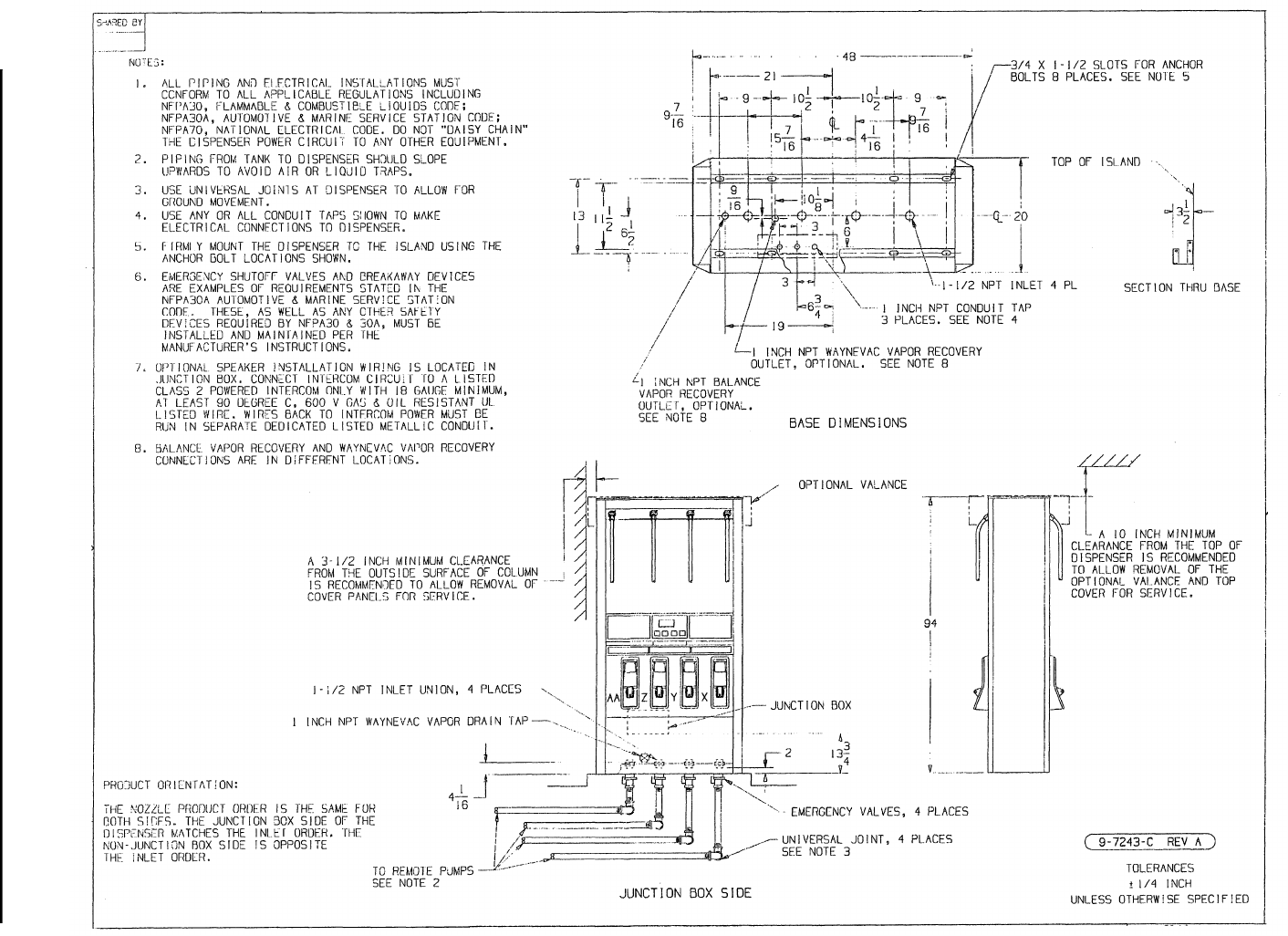
Figure C-10. 9-7243-C Installation Instructions - 3/V490D (Remote) - Except 3/V490D/U See 4-7243-C
72
March 2003 Part No. 920365 Rev B
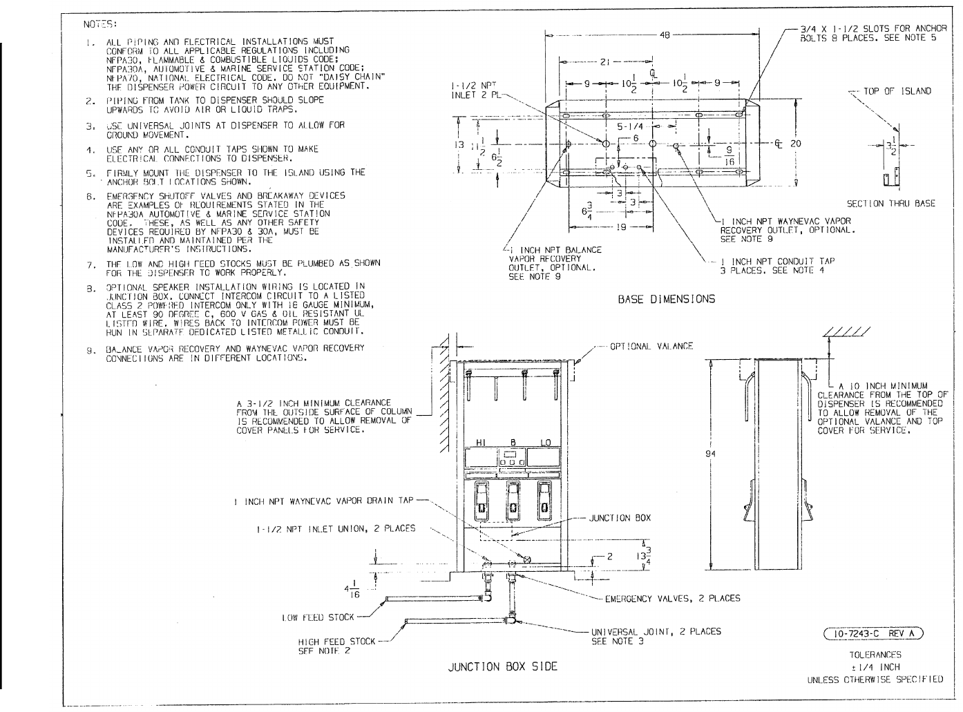
Figure C-11. 10-7243-C Installation Instructions - 3/V590D (Remote) - Except 3/V590D/U See 2-7243-C
73
March 2003 Part No. 920365 Rev B
Figure C-12. 11-7243-C Installation Instructions - 3/V591D (Remote)
74
March 2003 Part No. 920365 Rev B
Figure C-13. 9-7193-C Installation Instructions - 3/V590P/U and 3/V595P/U (Suction)
75
March 2003 Part No. 920365 Rev B
Figure C-14. 10-7193-C Installation Instructions - 3/V390P and 3/V390P/U (Suction)
76
March 2003 Part No. 920365 Rev B
Figure C-15. 11-7193-C Installation Instructions - 3/V399P (Suction)
77
March 2003 Part No. 920365 Rev B
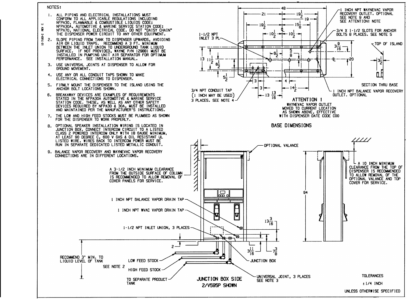
Figure C-16. 12-7193-C Installation Instructions - 3/V591P and 3/V595P (Suction) - Except 3/V595P/U See 9-7193-C
78
March 2003 Part No. 920365 Rev B
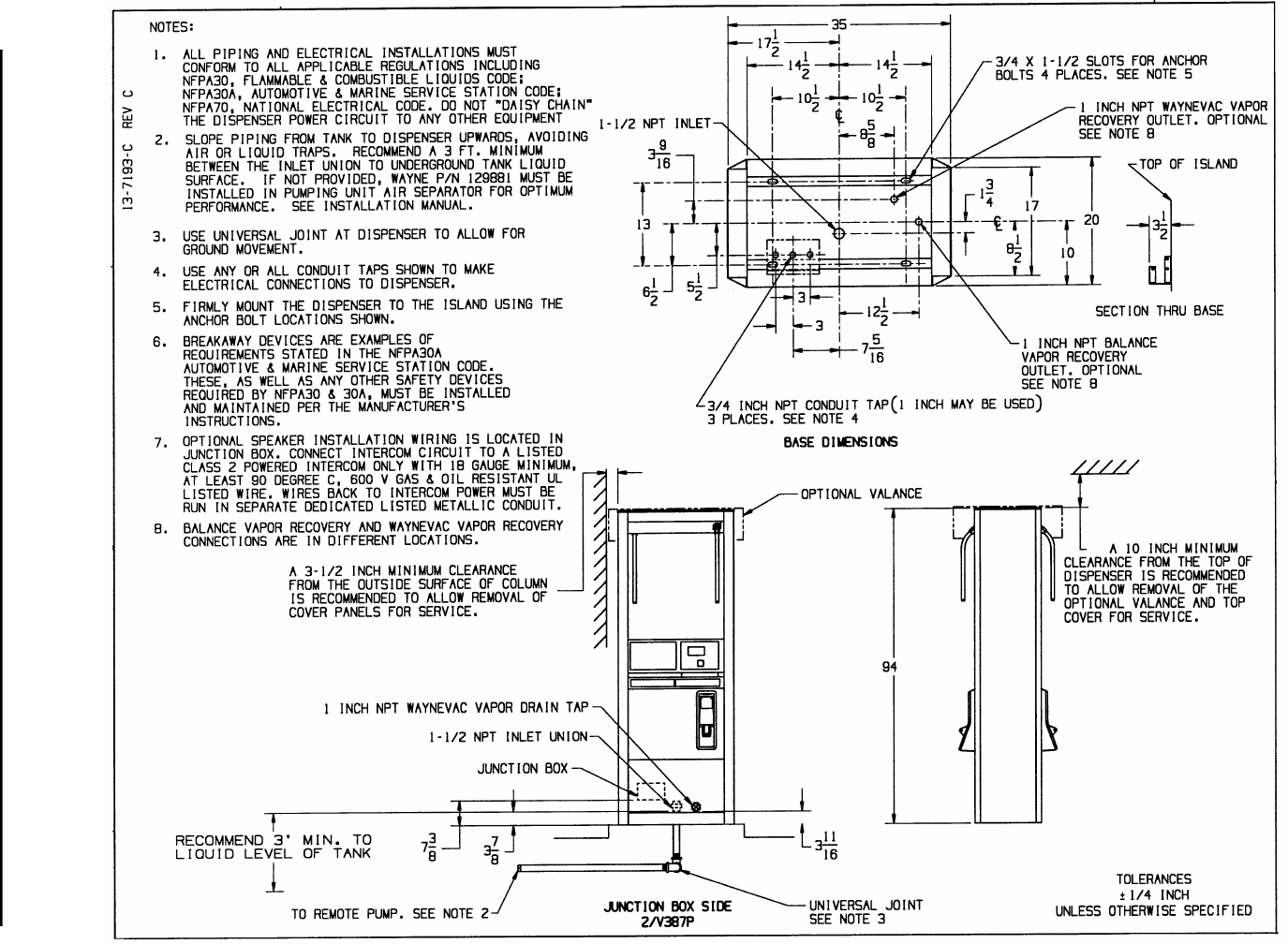
Figure C-17. 13-7193-C Installation Instructions - 3/V387P (Suction)
79
March 2003 Part No. 920365 Rev B
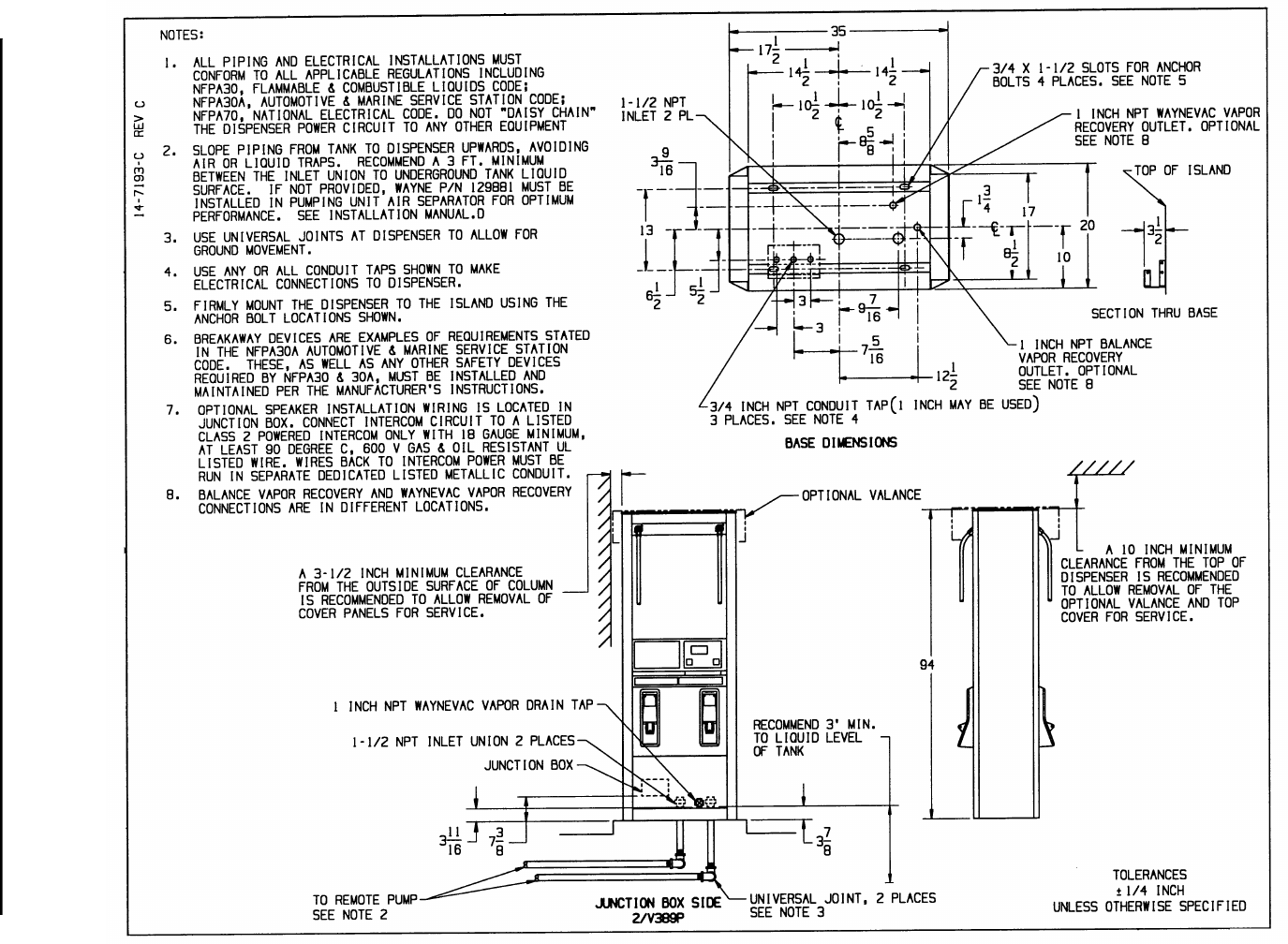
Figure C-18. 14-7193-C Installation Instructions - 3/V389P (Suction)
80
March 2003 Part No. 920365 Rev B
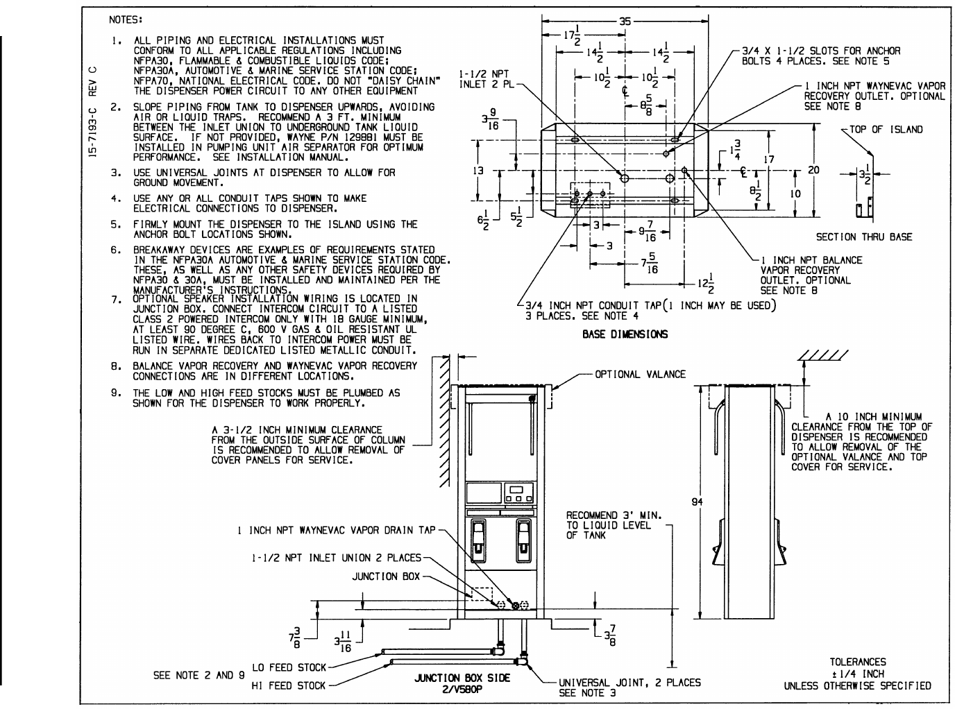
Figure C-19. 15-7193-C Installation Instructions - 3/V580P and 3/V585P (Suction)
81
March 2003 Part No. 920365 Rev B
Figure C-20. 1-7157-C Installation Wiring - 3/V390D (Remote) - Except 3/V390D/U See 13-7157-C
82
March 2003 Part No. 920365 Rev B
Figure C-21. 2-7157-C Installation Wiring - 3/V389D and 3/V399D (Remote)
83
March 2003 Part No. 920365 Rev B
Figure C-22. 3-7157-C Installation Wiring - 3/V490D (Remote)
84
March 2003 Part No. 920365 Rev B
Figure C-23. 4-7157-C Installation Wiring - All Remote Blender Models - Except 3/V591D and 3/V595D See 10-7157-C.
85
March 2003 Part No. 920365 Rev B
Figure C-24. 5-7157-C Installation Wiring - 3/V387D (Remote).
86
March 2003 Part No. 920365 Rev B
Figure C-25. 10-7157-C Installation Wiring - 3/V591D and 3/V595D (Remote) - Except 3/V595D/U See 4-7157-C
87
March 2003 Part No. 920365 Rev B
Figure C-26. 13-7157-C Installation Wiring - 3/V390D/U (Remote)
88
March 2003 Part No. 920365 Rev B
Figure C-27. 6-7157-C Installation Wiring - 3/V390P (Suction).
89
March 2003 Part No. 920365 Rev B
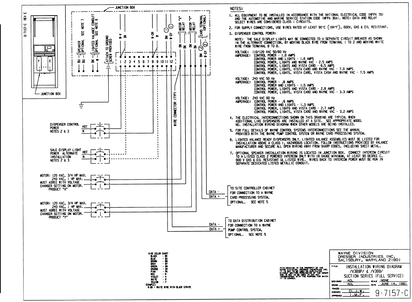
Figure C-28. 9-7157-C Installation Wiring - 3/V389P and 3/V399P (Suction).
90
March 2003 Part No. 920365 Rev B
Figure C-29. 19-7157-C Installation Wiring - 3/V590P/U and 3/V595P/U (Suction)
91
March 2003 Part No. 920365 Rev B
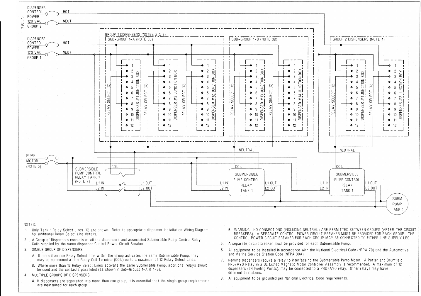
Figure C-30. 7151-C Typical Dispenser Site Wiring Diagram
92
March 2003 Part No. 920365 Rev B
Figure C-31. 10196-B Dispenser Dimensional Drawing - Inside Footprint

93
March 2003 Part No. 920365 Rev B
APPENDIX D SITE INTERCONNECTION DIAGRAMS
94
Part No. 920365 Rev B March 2003
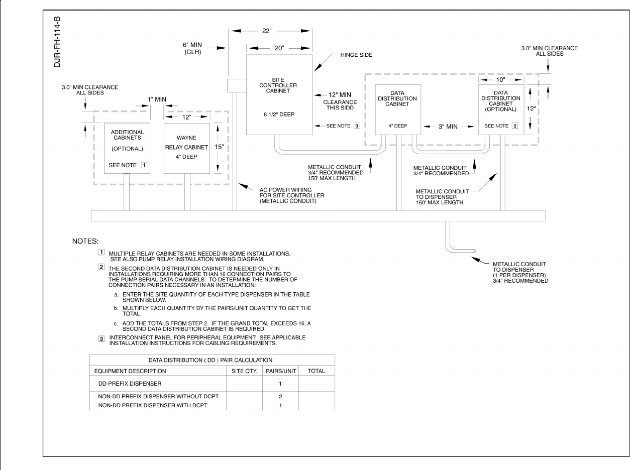
Figure D-1 Backroom Installation - Wayne Management Control System.
95
March 2003 Part No. 920365 Rev B
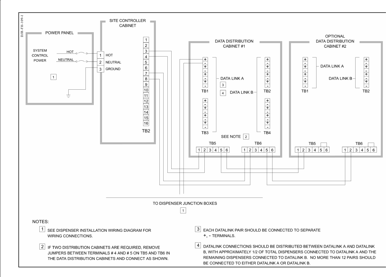
Figure D-2 Interconnection Wiring Diagram - Data Distribution Cabinet To Dispensers.
96
Part No. 920365 Rev B March 2003
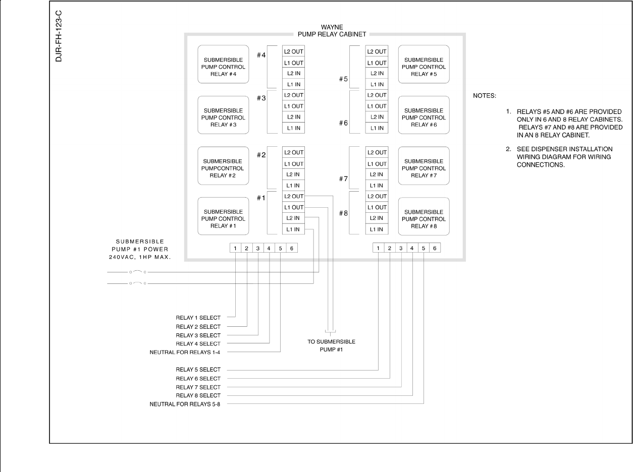
Figure D-3 Pump Relay Installation Wiring Diagram.
97
March 2003 Part No. 920365 Rev B
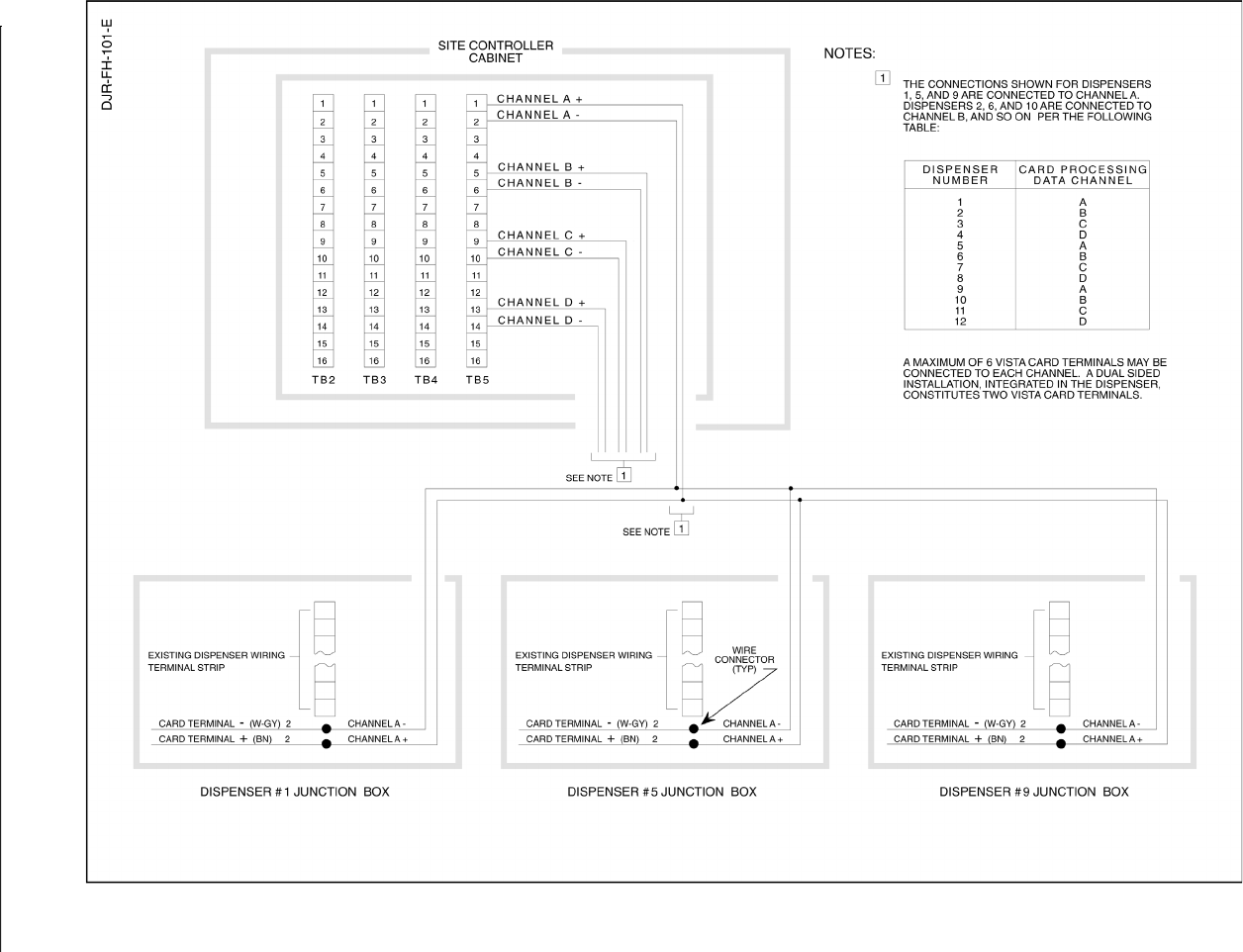
Figure D-4 Interconnection Wiring Diagram - Dispenser Card Processing (CATs) .

98
Part No. 920365 Rev B March 2003

INSTALLATION & OPERATION MANUAL
3/Vista Series Blending and Non-blending
Suction Pumps and Remote Dispensers
Written by S. G. Martin
This manual was produced on a personal computer using Adobe® FrameMaker® and Photoshop®
Page design uses Times New Roman and Arial Fonts
Manuals were electronically produced on a Xerox Docutech Publishing System
Copyright © 2003 Dresser, Inc.
All rights reserved.
Printed in the United States of America.
Adobe® FrameMaker® and Photoshop®are trademarks of Adobe Systems, Inc.
This manual and the software described within are furnished under license and may be used or copied only in
accordance with the terms of such license.
No part of this publication may be electronically or mechanically reproduced, stored in a retrieval system, or
transmitted, in any form or by any means, except as permitted by such license. Translation of this material to
another language without express written permission of Dresser, Inc. is prohibited.
The information in this publication is for informational use only and is subject to change without notice. The
contents should not be construed as a commitment by Dresser, Inc. who assumes no responsibility or liability
for inaccuracies that may appear in this publication.
Dresser Wayne, Dresser, Inc., is located at 3814 Jarrett Way, Austin TX 78728.
Wayne’s general telephone number is (512)-388-8311.

Dresser Wayne, Dresser, Inc. 3814 Jarrett Way, Austin, TX 78728 (512) 388-8311
Part No. 920365 Rev B ©2003 Dresser, Inc. 100/03/03
NOTE: “This equipment has been tested and found to comply with the
limits for a Class A digital device, pursuant to Part 15 of the FCC Rules.
These limits are designed to provide reasonable protection against
harmful interference when the equipment is operated in a commercial
environment. This equipment generates, uses, and can radiate radio
frequency energy and, if not installed and used in accordance with the
instruction manual, may cause harmful interference to radio communi-
cations. Operation of this equipment in a residential area is likely to
cause harmful interference in which case the user will be required to cor-
rect the interference at his own expense.”