Wayne Fueling Systems WAYNETRACII User Manual Sec 2

Wayne Fueling Systems LLC Sec 2

Contents

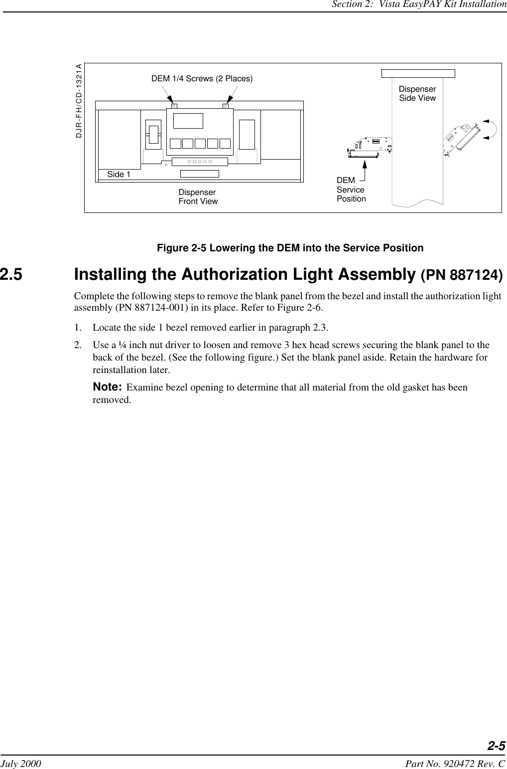
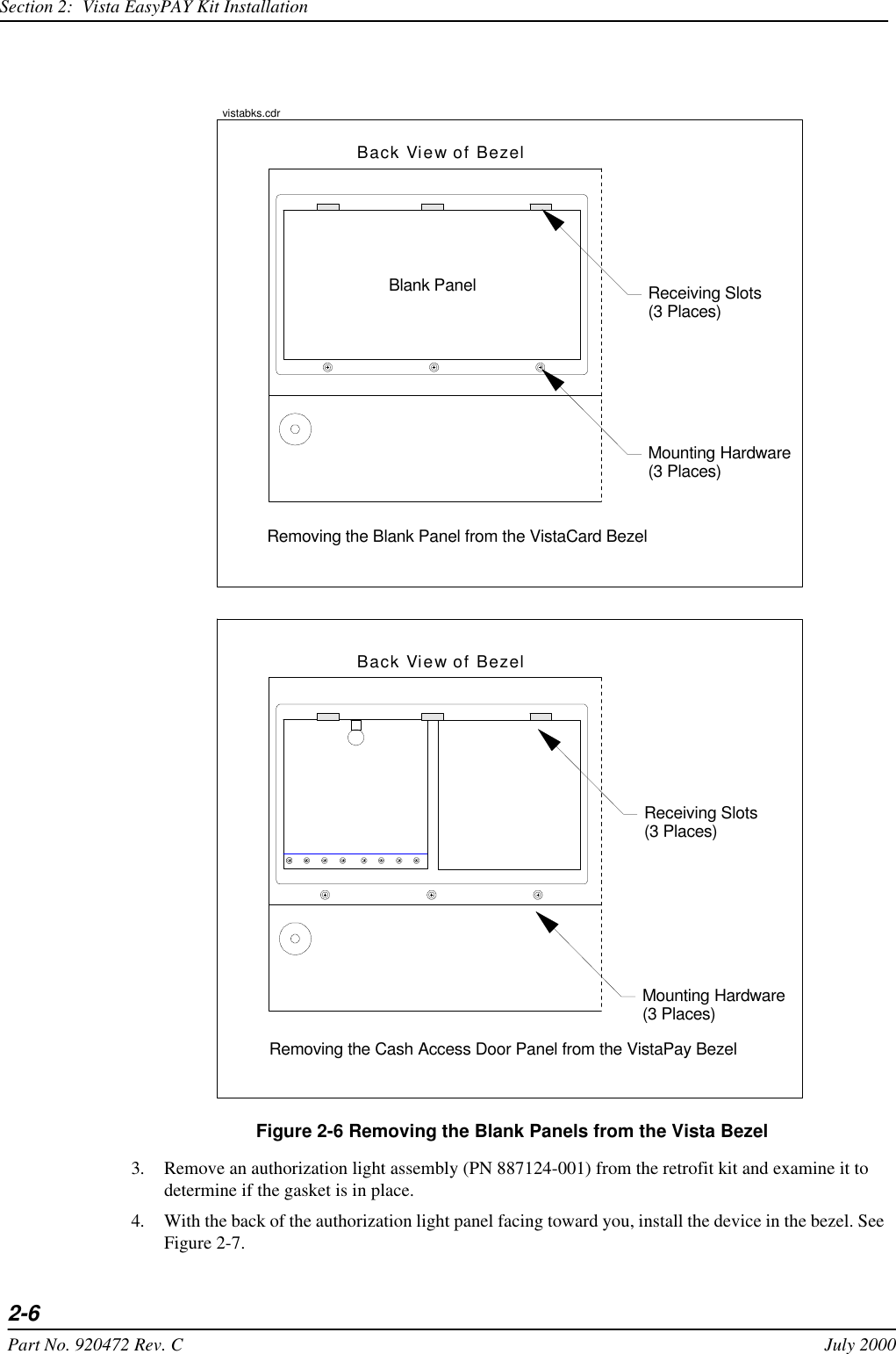
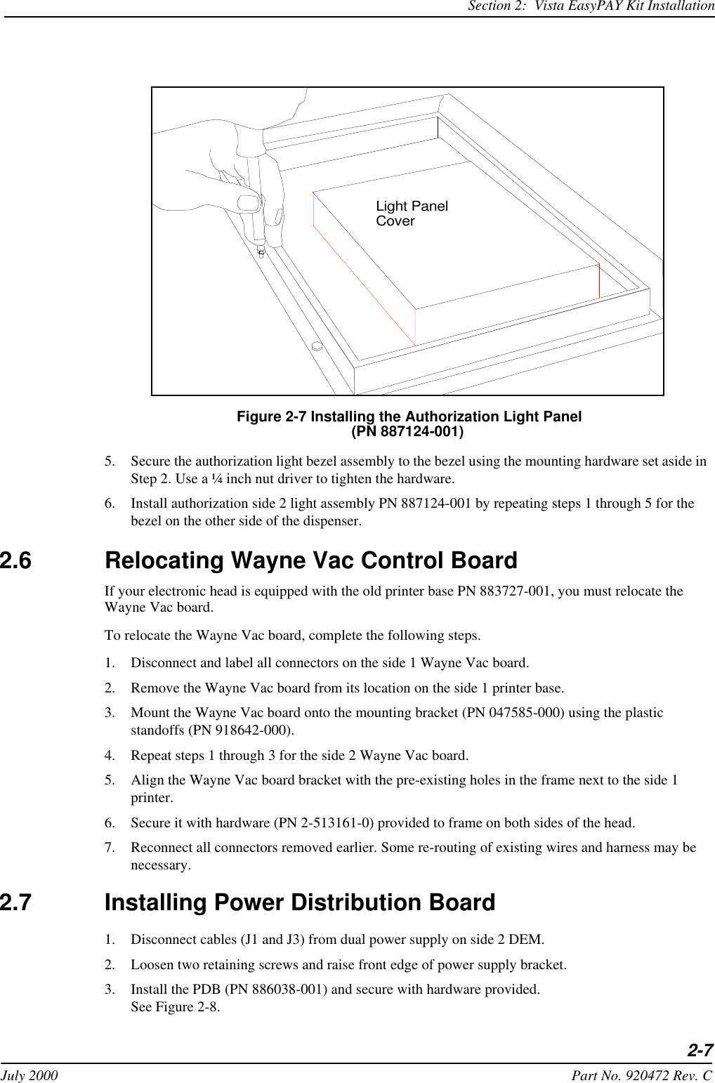
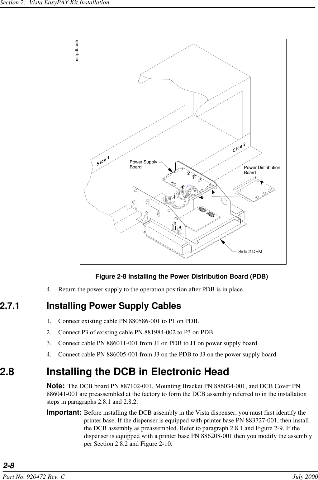
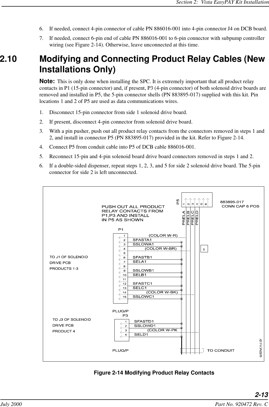
correction for installation manual section two

2-1July 2000 Part No. 920472 Rev. C Section     2Vista EasyPAY Kit Installation2.1 IntroductionThe information in this chapter explains how to install the EasyPAY retrofit kit (PN 887122-001). Note: It is necessary to identify Side 1 and Side 2 of the dispenser in order to carry out the instructions that follow.  Note that the dispenser ID plate is located on the lower left corner of the chassis frame on Side 1.  See Figure 2-16 for illustration.2.2 Removing Dispenser PowerBefore you begin installing the retrofit kit, perform the following steps to protect the kit assemblies from damage. 1. Close station to fuel purchases.2. Disconnect the power from dispensers at the power panel. Post a warning sign at the power panel stating that the equipment is being serviced.
2-2Part No. 920472 Rev. C July 2000Section 2:  Vista EasyPAY Kit Installation2.3 Removing the BezelsComplete the following steps to remove the bezels from the dispenser.1. Remove and save any temporary advertisement or instructional attachments from the bezel face. 2. Place an anti-static wrist strap (PN 916962 or equivalent) on your wrist and attach the other end of the wrist strap to an earth grounding point.3. Disengage the advertisement (ad) panels. Unsnap the ad panel by pulling forward firmly on the top edge of the panel. Refer to Figure 2-1. Figure 2-1 Removing the Ad Panel4. If necessary, unlock the function switch door.5. Turn the wing fasteners on the left and right side of bezel counter clockwise. Refer to Figure 2-2.WAYNEWayne1112323Tilt the ad panel out and down toward you.1/4 Turn Phillips Head ScrewsAd PanelBlank PanelDJR-FH/CD-1302ALift For ReceiptLift For Receipt
Section 2:  Vista EasyPAY Kit Installation2-3July 2000 Part No. 920472 Rev. C Figure 2-2 Wing Fasteners on Bezel6. Rest the lower edge of the bezel on the dispenser and disconnect the following cables from the back of the bezel. a. If the bezel is equipped with a graphic display, disconnect the graphic display heater cable (PN 882827-001) plugged in the 2-conductor black connector that routes on the right side of the graphic display. See Figure 2-3. Figure 2-3 Disconnecting Cables on Back of Graphic Display Bezelb. Disconnect the cable assembly (PN 881524-001) installed in J5 on the annunciator interface board. Refer to Figure 2-3 and Figure 2-4 for the following steps. c. If the bezel is equipped with a Push-to-Start (PTS) bar, disconnect the cable assembly (PN 881692-01 or 881693-01) plugged in the 13-pin connector on the back of the bezel.d. If the bezel is equipped with a CPM and a DES keypad, disconnect the cable assembly (PN 880963-02) plugged in the 4-pin connector on the DES keypad cable.e. If the bezel is equipped with KDC and a DES keypad is present, disconnect the cable assembly (PN 880963-01) plugged in the 4-pin DES keypad cable.WAYNE2211334432PTS BarAreaAd Panel (lowered)Ad Panel FastenersWing FastenersFunction Switch Door LockDJR-CD-1303ALift For ReceiptRear View of CPM BezelJ3JP1J5DJR-FH/CD-1304AGraphic Display Adapter Board(Part No. 882440-xxx)DES Keypad4-Pin DES Keypad CableVista Annunciator InterfaceBoard (Part No. 883074-xx)
2-4Part No. 920472 Rev. C July 2000Section 2:  Vista EasyPAY Kit Installationf. Repeat steps 3 through 6 to remove the bezel on the other side of the dispenser.2.4 Lowering the DEMsPerform the following steps to lower the DEM(s) (Display Electronic Modules) to the service position.1. Use a slotted screwdriver to loosen two ¼ turn screws located at the top of the DEM. Refer to Figure 2-5.2. Lower the DEM to the service position.3. Repeat steps 1 and 2 for the DEM on the other side of the dispenser. Figure 2-4 Disconnecting Cables on Bezel BackDJR-FH/CD-1107ARear View of KDC BezelRear View of CPM BezelJ4J2J5J9J3Captive Screw(5 Places)Rain CatcherJ1J10Display BoardDisplay BracketMounting Screw(4 Places)J4 on AnnunciatorInterface Board(Part No. 880869-xx)J4J5J2 J1Display BracketMounting Screw(4 Places)Display BoardAnnunciator Interface Board(Part No. 881182-xxor 883072-xx)
Section 2:  Vista EasyPAY Kit Installation2-5July 2000 Part No. 920472 Rev. C Figure 2-5 Lowering the DEM into the Service Position2.5 Installing the Authorization Light Assembly (PN887124)Complete the following steps to remove the blank panel from the bezel and install the authorization light assembly (PN 887124-001) in its place. Refer to Figure 2-6. 1. Locate the side 1 bezel removed earlier in paragraph 2.3.2. Use a ¼ inch nut driver to loosen and remove 3 hex head screws securing the blank panel to the back of the bezel. (See the following figure.) Set the blank panel aside. Retain the hardware for reinstallation later. Note: Examine bezel opening to determine that all material from the old gasket has been removed.DEM 1/4 Screws (2 Places)DispenserFront ViewSide 1 DEMServicePositionDispenserSide ViewDJR-FH/CD-1321A
2-6Part No. 920472 Rev. C July 2000Section 2:  Vista EasyPAY Kit Installation Figure 2-6 Removing the Blank Panels from the Vista Bezel3. Remove an authorization light assembly (PN 887124-001) from the retrofit kit and examine it to determine if the gasket is in place.4. With the back of the authorization light panel facing toward you, install the device in the bezel. See Figure 2-7. Blank PanelBack View of BezelReceiving Slots(3 Places)Mounting Hardware(3 Places)Back View of BezelMounting Hardware(3 Places)Receiving Slots(3 Places)Removing the Blank Panel from the VistaCard BezelRemoving the Cash Access Door Panel from the VistaPay Bezelvistabks.cdr
Section 2:  Vista EasyPAY Kit Installation2-7July 2000 Part No. 920472 Rev. C Figure 2-7 Installing the Authorization Light Panel (PN 887124-001)5. Secure the authorization light bezel assembly to the bezel using the mounting hardware set aside in Step 2. Use a ¼ inch nut driver to tighten the hardware. 6. Install authorization side 2 light assembly PN 887124-001 by repeating steps 1 through 5 for the bezel on the other side of the dispenser.2.6 Relocating Wayne Vac Control BoardIf your electronic head is equipped with the old printer base PN 883727-001, you must relocate the Wayne Vac board. To relocate the Wayne Vac board, complete the following steps. 1. Disconnect and label all connectors on the side 1 Wayne Vac board.2. Remove the Wayne Vac board from its location on the side 1 printer base.3. Mount the Wayne Vac board onto the mounting bracket (PN 047585-000) using the plastic standoffs (PN 918642-000). 4. Repeat steps 1 through 3 for the side 2 Wayne Vac board.5. Align the Wayne Vac board bracket with the pre-existing holes in the frame next to the side 1 printer.6. Secure it with hardware (PN 2-513161-0) provided to frame on both sides of the head.7. Reconnect all connectors removed earlier. Some re-routing of existing wires and harness may be necessary. 2.7 Installing Power Distribution Board1. Disconnect cables (J1 and J3) from dual power supply on side 2 DEM.2. Loosen two retaining screws and raise front edge of power supply bracket.3. Install the PDB (PN 886038-001) and secure with hardware provided. See Figure 2-8.Light PanelCover
2-8Part No. 920472 Rev. C July 2000Section 2:  Vista EasyPAY Kit Installation Figure 2-8 Installing the Power Distribution Board (PDB)4. Return the power supply to the operation position after PDB is in place. 2.7.1 Installing Power Supply Cables 1. Connect existing cable PN 880586-001 to P1 on PDB.2. Connect P3 of existing cable PN 881984-002 to P3 on PDB.3. Connect cable PN 886011-001 from J1 on PDB to J1 on power supply board.4. Connect cable PN 886005-001 from J3 on the PDB to J3 on the power supply board.2.8 Installing the DCB in Electronic HeadNote: The DCB board PN 887102-001, Mounting Bracket PN 886034-001, and DCB Cover PN 886041-001 are preassembled at the factory to form the DCB assembly referred to in the installation steps in paragraphs 2.8.1 and 2.8.2.Important: Before installing the DCB assembly in the Vista dispenser, you must first identify the printer base. If the dispenser is equipped with printer base PN 883727-001, then install the DCB assembly as preassembled. Refer to paragraph 2.8.1 and Figure 2-9. If the dispenser is equipped with a printer base PN 886208-001 then you modify the assembly per Section 2.8.2 and Figure 2-10.Power SupplyBoardSide 2 DEMinstpdb.cdrPower DistributionBoard
Section 2:  Vista EasyPAY Kit Installation2-9July 2000 Part No. 920472 Rev. C2.8.1 Installing DCB Assembly in Electronic Heads Equipped with Printer Base PN 883727-001If you are installing the DCB in a Vista with the "old" printer base PN 883727-001, refer to Figure 2-9. Figure 2-9 EasyPAY Assembly for Use With Old Printer Base PN 883727-0011. If there are any ground wires attached to the lower DCPT frame, be sure to disconnect them before installing the DCB assembly. Once the DCB is in place, then reconnect.2. Install the new DCB assembly such that it is facing the heater fan.
2-10Part No. 920472 Rev. C July 2000Section 2:  Vista EasyPAY Kit Installation3. Secure the DCB assembly to frame on both sides of head with screws (PN 2-513161-0) provided in kit.2.8.2 Installing DCB Assembly in Electronic Heads Equipped with Printer Base PN 886208-001To install the DCB assembly board in an electronic head equipped with the "Z" printer base Mounting Bracket, complete the following steps. Refer to Figure 2-10, Figure 2-11, and Figure 2-12.1. Wearing a suitable grounding strap attached to an earth ground, disassemble the DCB assembly by removing and discarding the Mounting Bracket PN 886034-001 and DCB Cover PN 886041-001 from the DCB board PN 887102-001, retaining the hardware.2. Attach four standoffs PN 5002001 provided in kit to the DCB board mounting holes (on component side) with screws retained from the previous step. Figure 2-10 Securing Stand-offs to DCBImportant: For the following step, make sure the 6 white connectors on the DCB board face side 2 of the head. This allows correct installation of the interface and power cables. See Figure 2-11.3. Be sure to disconnect any ground wires attached to the lower electronic head frame before installing the DCB. Once DCB is installed, then reconnect any ground wires.4. From side 1, place the DCB board beside the printer "Z" base located to the right of the DEM.5. Align the DCB board standoffs with the four pre-existing holes in the "Z" printer bracket and secure with nuts (PN 6019401) provided.
Section 2:  Vista EasyPAY Kit Installation2-11July 2000 Part No. 920472 Rev. C Figure 2-11 Installing DCB in Vista with Printer Base PN 886208-001 (Viewed from Side 1) Figure 2-12 DCB Mounted in Vista Printer Base PN 886208-001 (Viewed from Side 2)Install with connectors toward side 2 ofelectronic head.Install DCB on heater fan side of "Z" bracket.
2-12Part No. 920472 Rev. C July 2000Section 2:  Vista EasyPAY Kit Installation Figure 2-13 DCB Connections2.9 Installing Cables in Electronic Head Complete the following steps to install the new cables in the dispenser head. Refer to Figure 2-13 and Figure A-1 (Interconnection Wiring Diagram).Note: You may have to remove one or more existing tie-wraps to allow cables to reach appropriate locations when re-routed during this installation.2.9.1 Installing Power and DCB Assembly Cables (Refer to Appendix A Wiring Diagram and Figure 2-13)1. Route cable PN 886012-001 from side 1 DEM and plug into J4 of Power Distribution Board (PDB). Lay cable under printer support bracket.2. Route existing cable PN 884146-001 under printer bracket to side 1 and connect to J5 on PDB.3. Connect cable PN 886013-001 to J2 on PDB, route across center of dispenser and connect to J3 on DCB.4. Connect cable PN 886014-001 to DCB 6-pin connector J7 and route to side 1.5. Connect second cable PN 886014-001 to DCB 6-pin connector J8 and route to side 2.J7J8J4J9J10J11J12J3
Section 2:  Vista EasyPAY Kit Installation2-13July 2000 Part No. 920472 Rev. C6. If needed, connect 4-pin connector of cable PN 886016-001 into 4-pin connector J4 on DCB board.7. If needed, connect 6-pin end of cable PN 886016-001 to 6-pin connector with subpump controller wiring (see Figure 2-14). Otherwise, leave unconnected at this time.2.10 Modifying and Connecting Product Relay Cables (New Installations Only)Note: This is only done when installing the SPC. It is extremely important that all product relay contacts in P1 (15-pin connector) and, if present, P3 (4-pin connector) of both solenoid drive boards are removed and installed in P5, the 5-pin connector shells (PN 883895-017) supplied with this kit. Pin locations 1 and 2 of P5 are used as data communications wires.1. Disconnect 15-pin connector from side 1 solenoid drive board.2. If present, disconnect 4-pin connector from solenoid drive board.3. With a pin pusher, push out all product relay contacts from the connectors removed in steps 1 and 2, and install in connector P5 (PN 883895-017) provided in the kit. Refer to Figure 2-14. 4. Connect P5 from conduit cable into P5 of DCB cable 886016-001. 5. Reconnect 15-pin and 4-pin solenoid board drive board connectors removed in steps 1 and 2.6. If a double-sided dispenser, repeat steps 1, 2, 3, and 5 for side 2 solenoid drive board. The 5-pin connector for side 2 is left unconnected. Figure 2-14 Modifying Product Relay Contactssoldrvcn.cdr
2-14Part No. 920472 Rev. C July 2000Section 2:  Vista EasyPAY Kit Installation2.11 Addressing LightboardsThe lightboards must be addressed before the system will operate successfully. Refer to the following table for lightboard dipswitch settings. Table 2-1 Dipswitch Settings for Addressing Lightboards2.12 Connecting Bezel Wiring and Reinstalling the BezelsComplete the following steps to reconnect cables, reinstall the DEMs, bezels, and tune antenna.1. Return the side 1 DEM to the operating position. Make sure you do not bind or crimp wires.2. Secure the side 1 DEM to the pumphead using a slotted screwdriver to tighten two ¼ turn screws located at the top of the DEM. Refer to paragraph 2.4.3. Rest the side 1 bezel on the base frame of the electronic head.4. Reconnect all bezel cables that were removed in paragraph 2.3.5. For side 1 bezel, connect cable PN 886012-001 to J1 on light board assembly.6. Connect cable PN 886014-001 to J3 of the light board assembly.7. Unbundle the ground strap found attached to the light board bezel housing.8. Slip  the small hole on the ground strap over the end of the lock screw.9. Turn the lock screw to thread the ground strap as far as possible onto the screw.10. Close bezel and secure locking screws.11. Repeat steps 1 through 4 and steps 7 through 9 for side 2 bezel.12. For side 2 bezel, connect cable PN 884146-001 to J1 on light board assembly.13. Return power to CAT by setting DCPT power switch to ON.14. Snap ad panels back in place.Dip SwitchDecimal2 3 4 5AddressON OFF OFF OFF 1OFF ON OFF OFF 2ON ON OFF OFF 3OFF OFF ON OFF 4ON OFF ON OFF 5OFF ON ON OFF 6ON ON ON OFF 7OFF OFF OFF ON 8ON OFF OFF ON 9OFF ON OFF ON 10ON ON OFF ON 11OFF OFF ON ON 12ON OFF ON ON 13OFF ON ON ON 14ON ON ON ON 15
Section 2:  Vista EasyPAY Kit Installation2-15July 2000 Part No. 920472 Rev. C2.13 Reapplying Power15. Reapply power to dispenser and refer to the test instructions in Chapter 4 and the service manual "System Tests for Dispenser Electronics" (PN 920353).2.14 Installing Patent and Serial Number DecalRefer to Figure 2-15 for the following steps:1. Remove EasyPAY serial number and FCC decals from kit.2. Locate the Dispenser ID plate on the lower left corner of side 1 on the chassis frame.3. Clean area of dirt and oil before you apply decals.4. Affix decals securely onto dispenser adjacent to existing ID plate. Figure 2-15 Dispenser Decal LocationModelIDPlateCIDSerial No.DecalFCCDecal
2-16Part No. 920472 Rev. C July 2000Section 2:  Vista EasyPAY Kit Installation2.15 System Power-UpComplete the following steps.1. To add power to the dispensers, turn power ON at the control power circuit breaker.2. To turn power ON to the CAT, complete one of the following steps:a. For dual sided dispensers, turn power ON to the CAT at the function switch located on the side 2 DEM. b. For single sided dispensers, turn power ON to the CAT at the function switch located on the side 1 DEM. Note: If the CAT retrofit unit does not respond to power-up, check all connections. Replace any defective components.

Navigation menu