Wireless Seismic 00104 Wireless Seismic Sensor User Manual DeploymentGuide
Wireless Seismic, Inc. Wireless Seismic Sensor DeploymentGuide
UserManual.wiki
>
Wireless Seismic
>
00104 User Manual
>
Users Manual Rev 1 Part 2 of 2
Contents
1.
Users Manual Rev 1 Part 1 of 2
2.
Users Manual Rev 1 Part 2 of 2
Users Manual Rev 1 Part 2 of 2
Navigation menu
Upload a User Manual
Namespaces
Wiki Guide
HTML
PDF
Info
Views
User Manual
Discussion / Help
Navigation
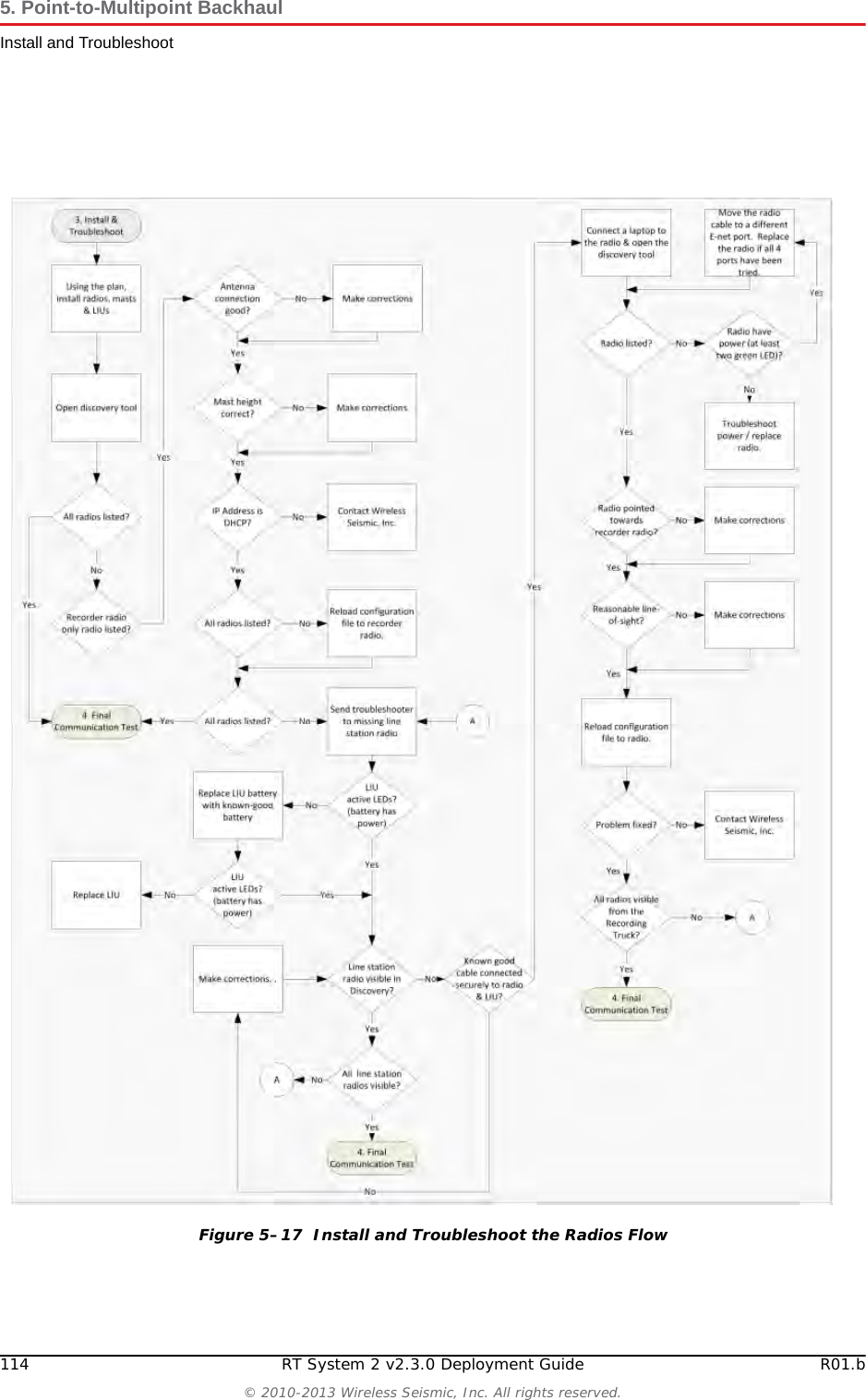
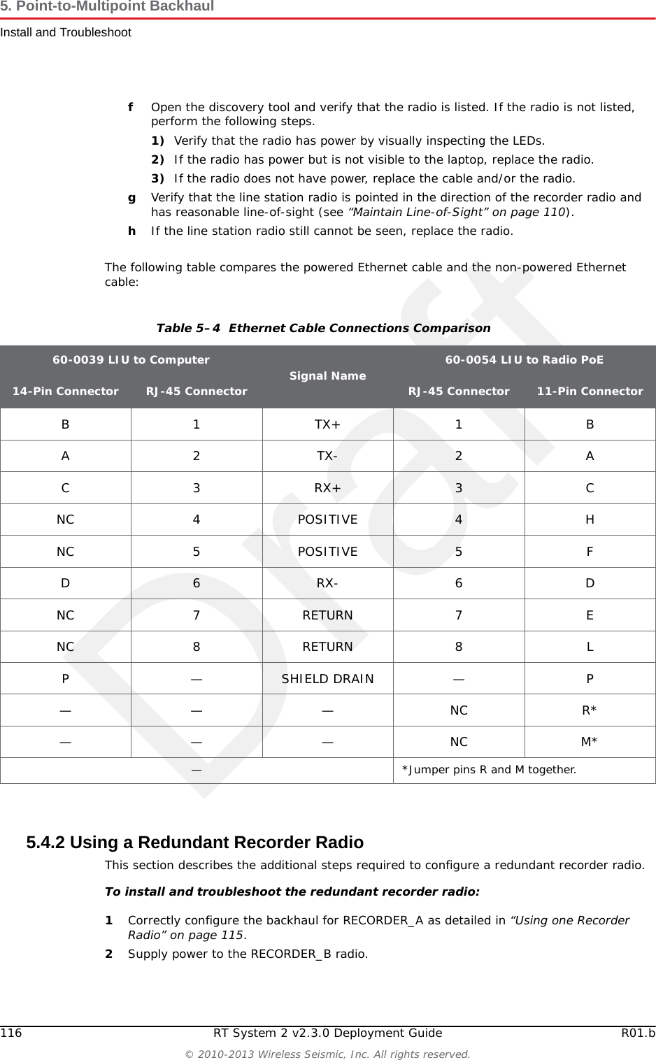


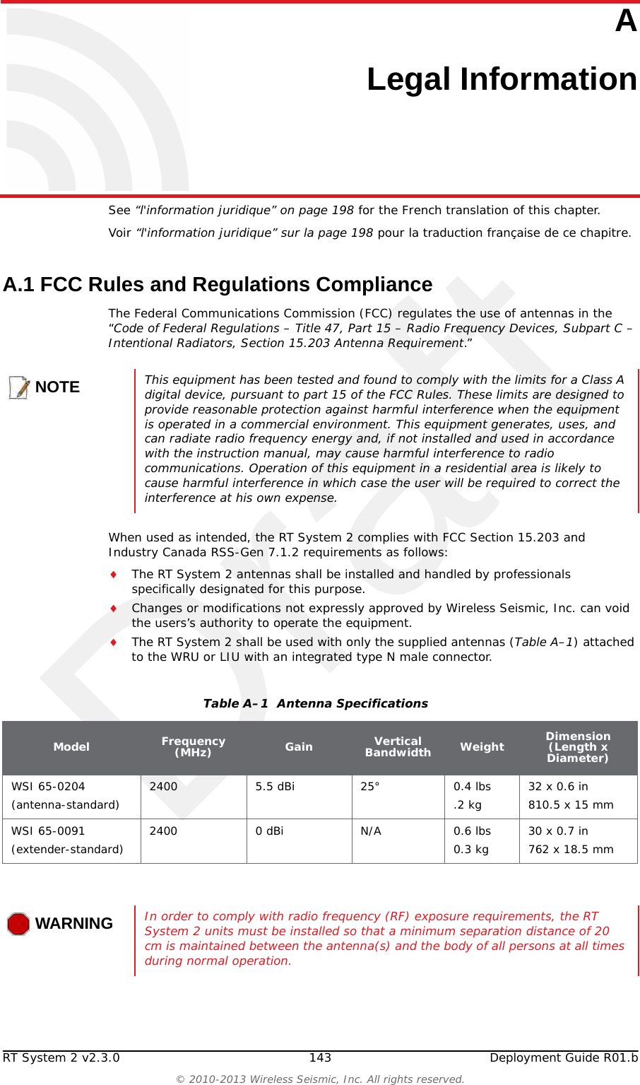
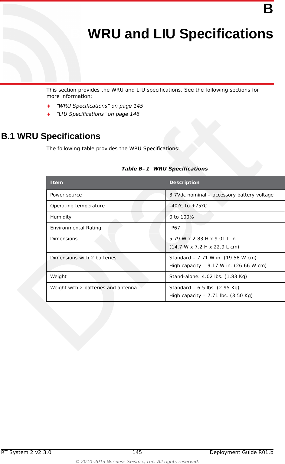
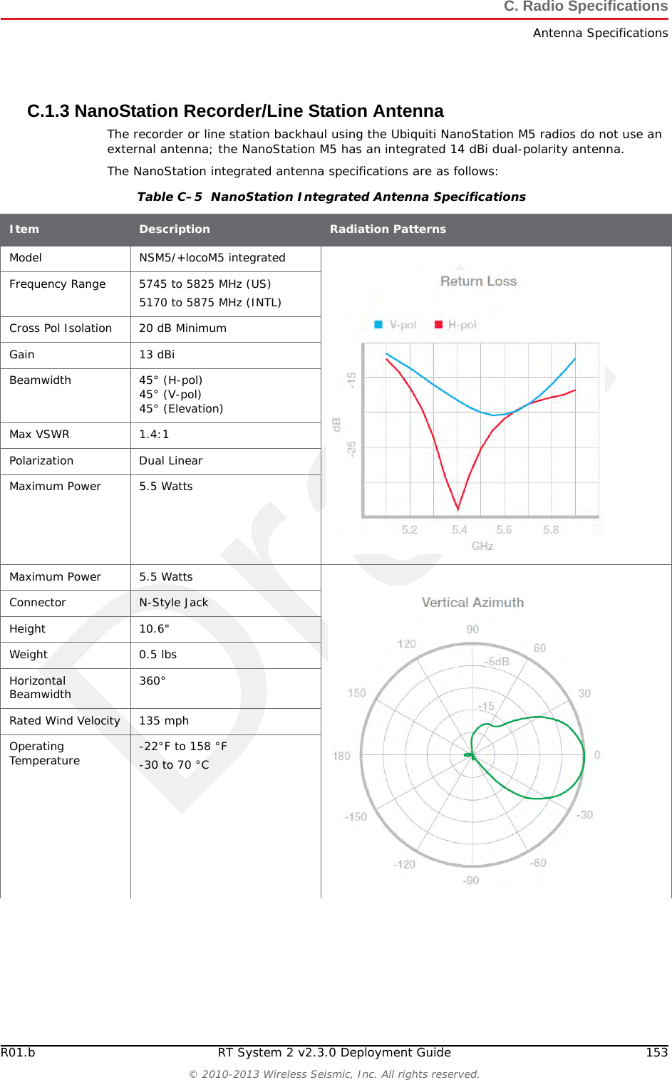
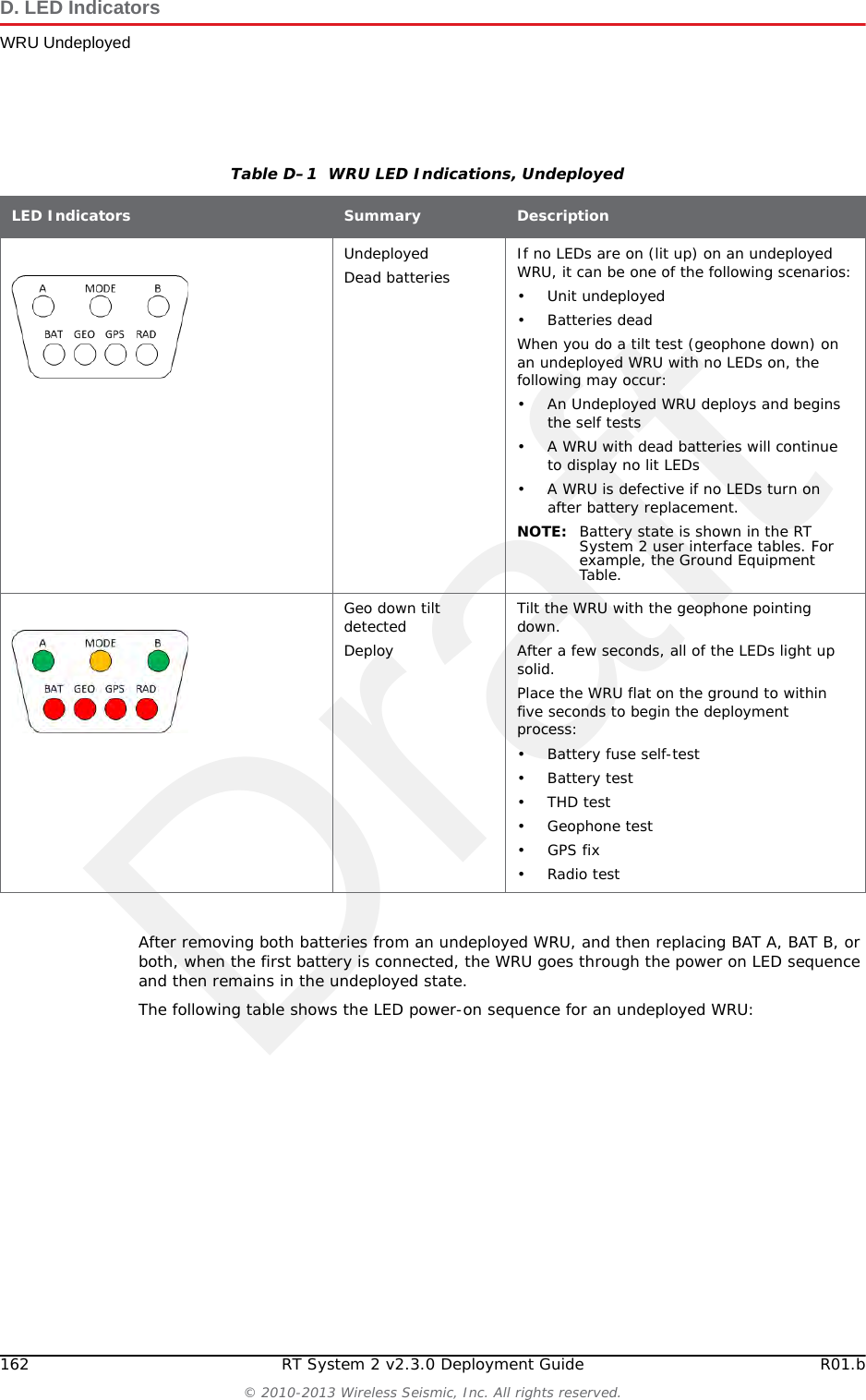
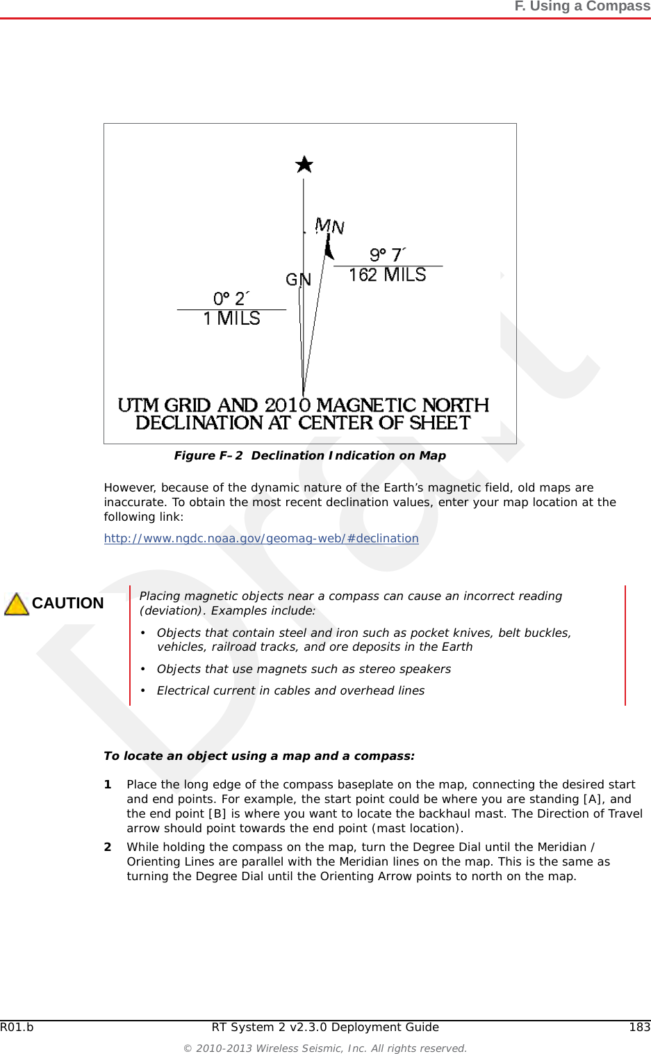
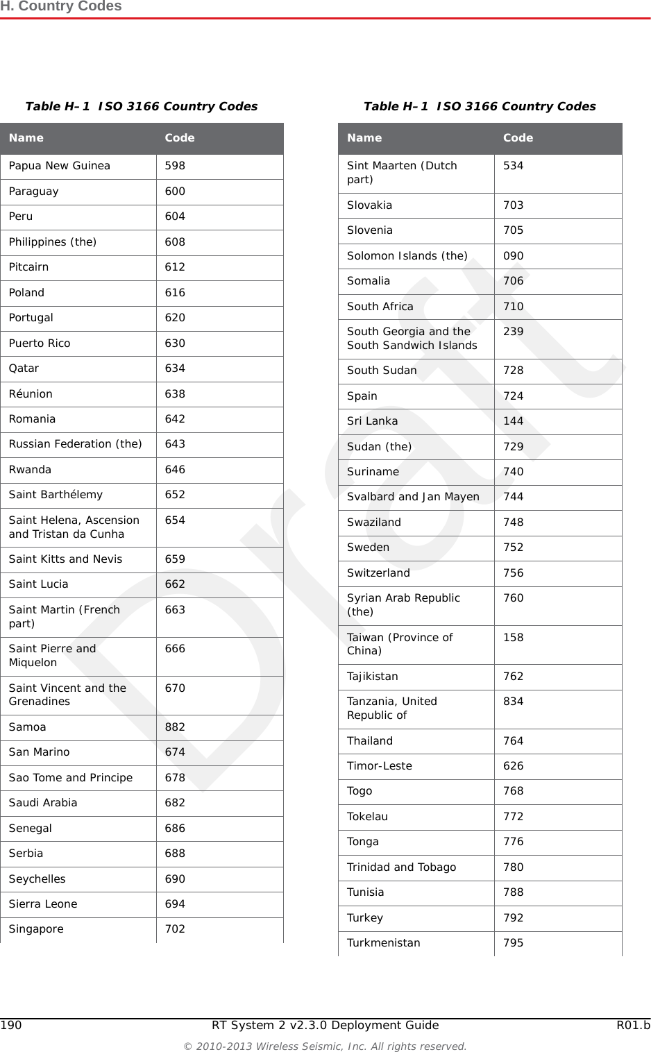
![DraftR01.b RT System 2 v2.3.0 Deployment Guide 183© 2010-2013 Wireless Seismic, Inc. All rights reserved.F. Using a CompassHowever, because of the dynamic nature of the Earth’s magnetic field, old maps are inaccurate. To obtain the most recent declination values, enter your map location at the following link:http://www.ngdc.noaa.gov/geomag-web/#declination To locate an object using a map and a compass:1Place the long edge of the compass baseplate on the map, connecting the desired start and end points. For example, the start point could be where you are standing [A], and the end point [B] is where you want to locate the backhaul mast. The Direction of Travel arrow should point towards the end point (mast location). 2While holding the compass on the map, turn the Degree Dial until the Meridian / Orienting Lines are parallel with the Meridian lines on the map. This is the same as turning the Degree Dial until the Orienting Arrow points to north on the map. Figure F–2 Declination Indication on MapCAUTIONPlacing magnetic objects near a compass can cause an incorrect reading (deviation). Examples include:• Objects that contain steel and iron such as pocket knives, belt buckles, vehicles, railroad tracks, and ore deposits in the Earth• Objects that use magnets such as stereo speakers• Electrical current in cables and overhead lines](https://usermanual.wiki/Wireless-Seismic/00104.Users-Manual-Rev-1-Part-2-of-2/User-Guide-2154857-Page-83.png)
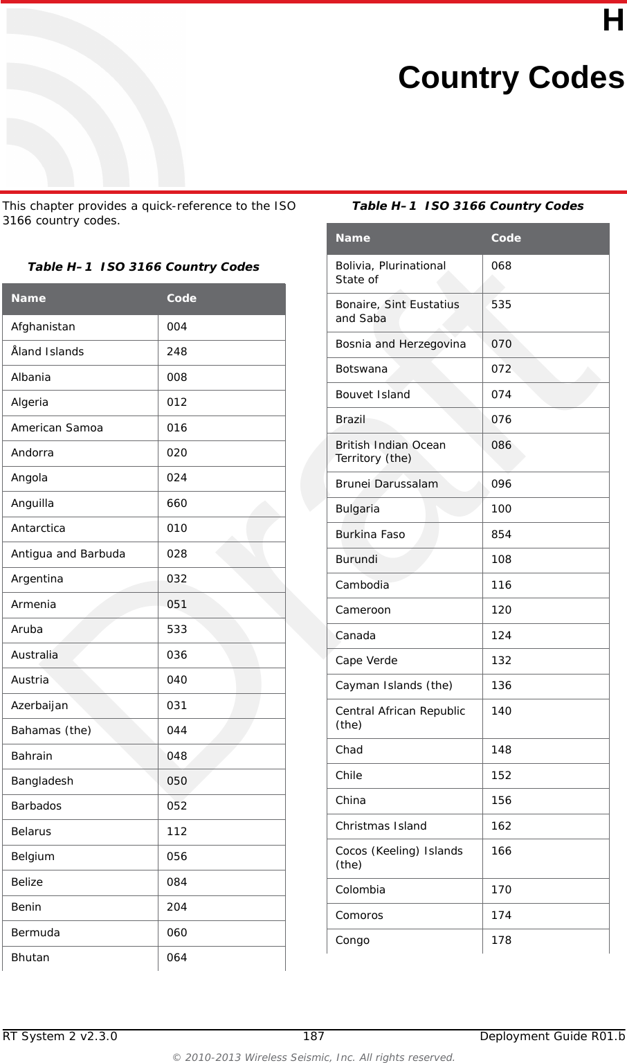
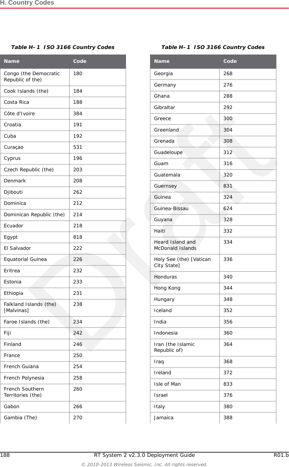
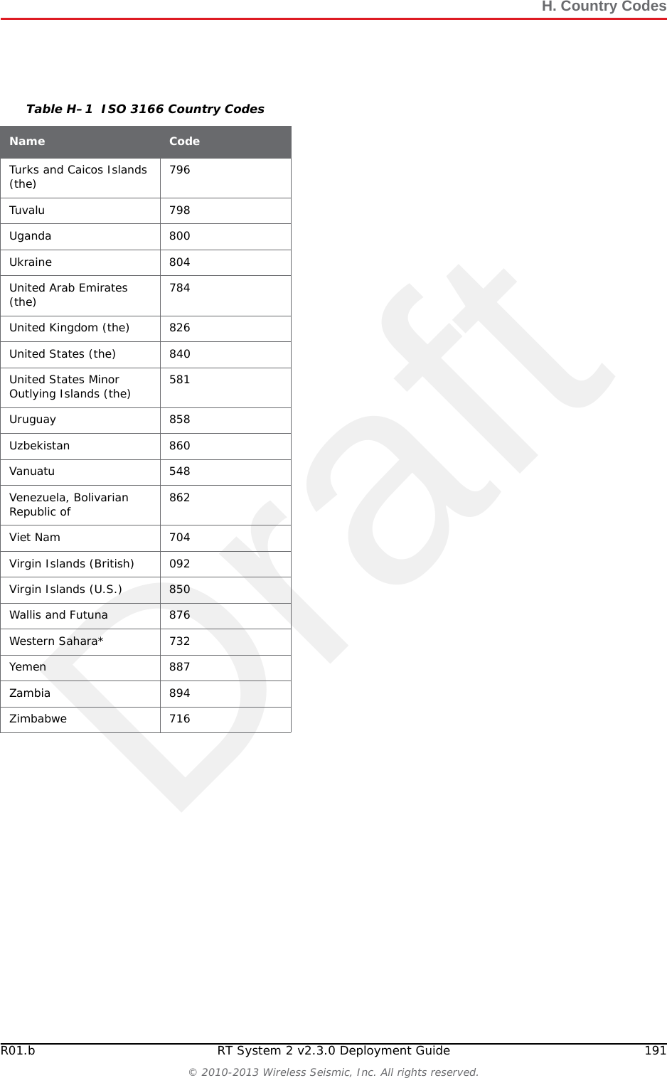
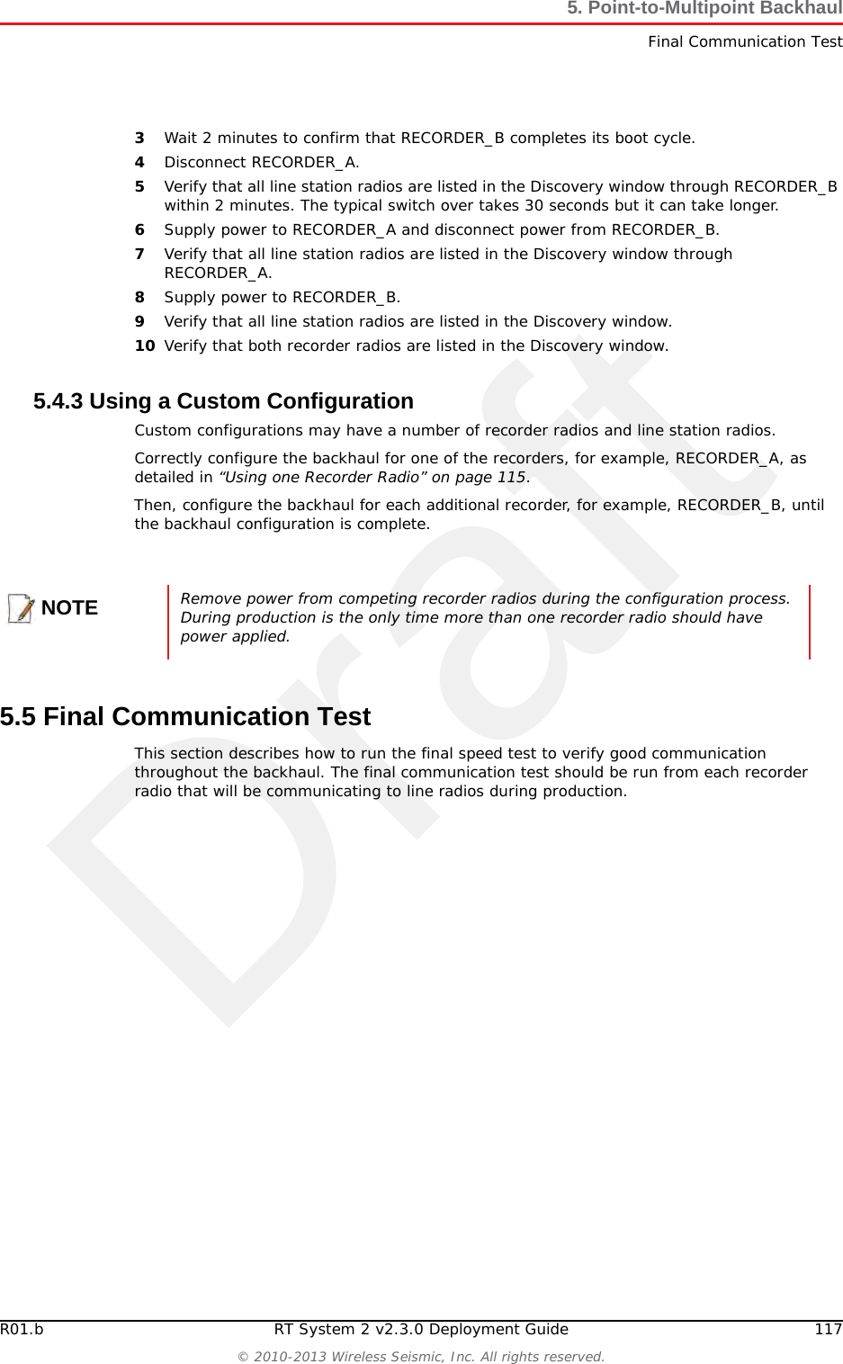
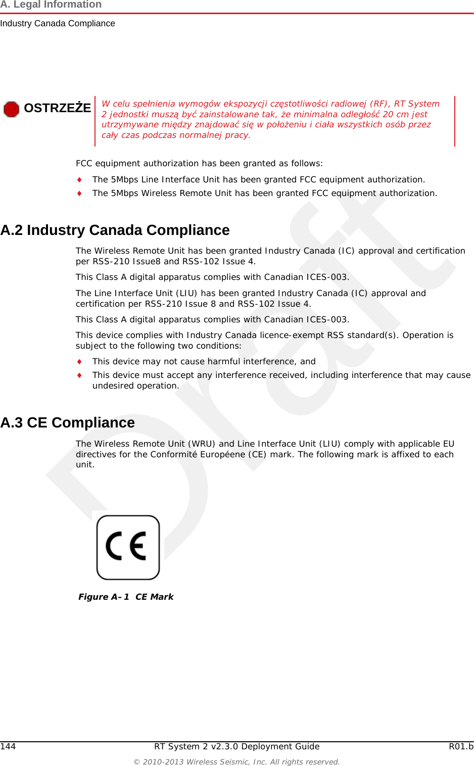
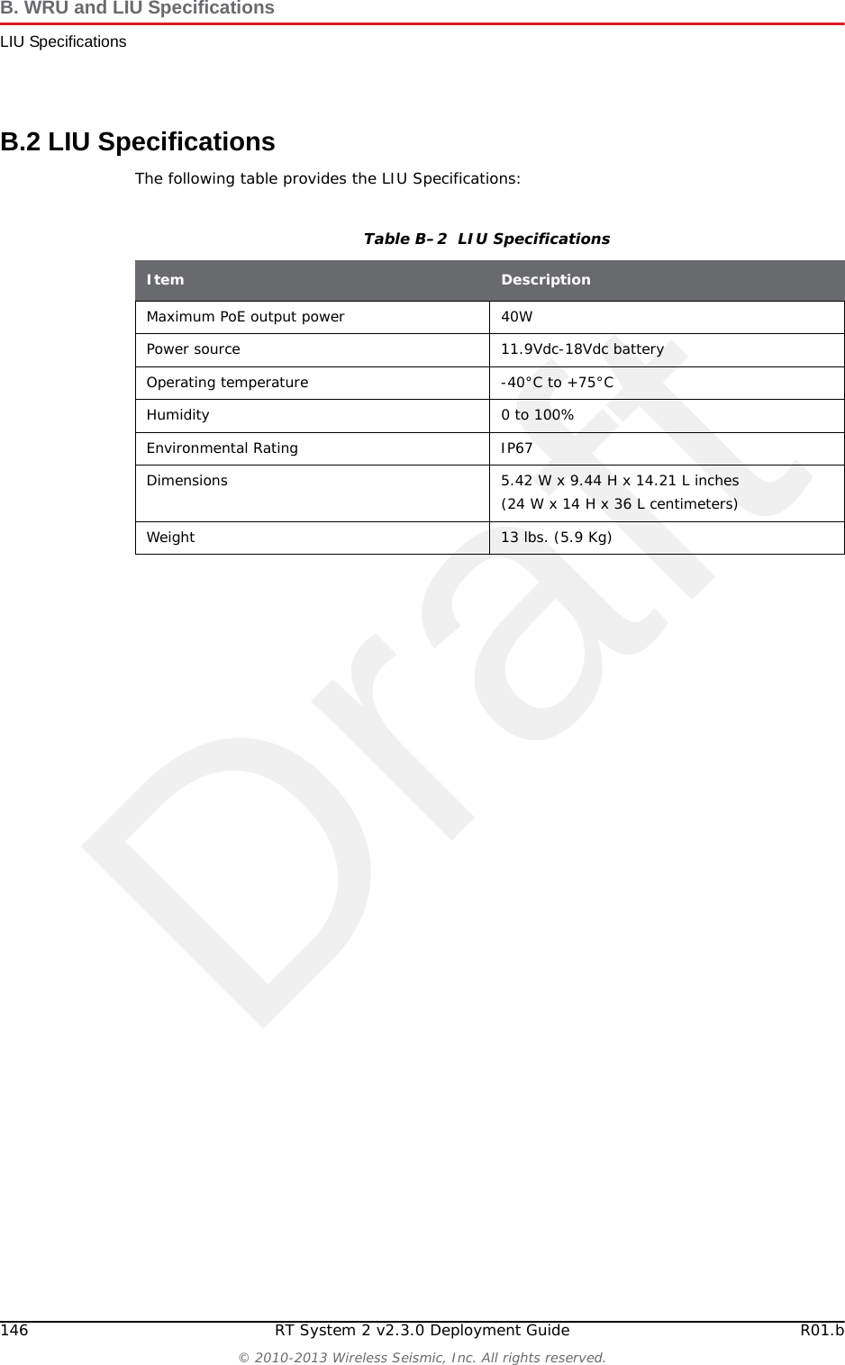
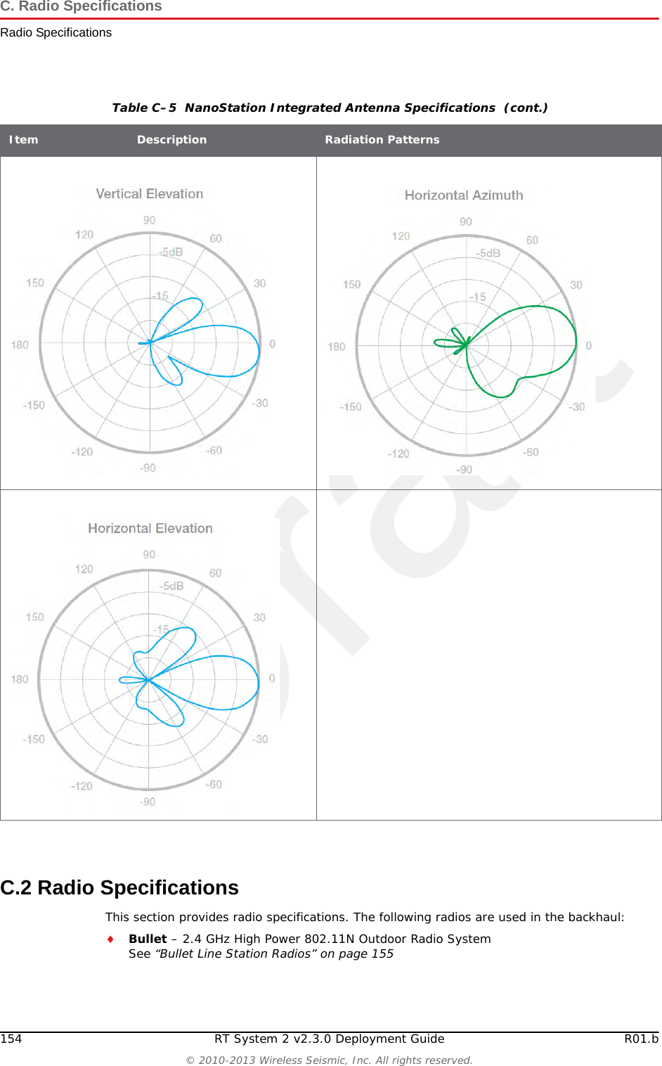
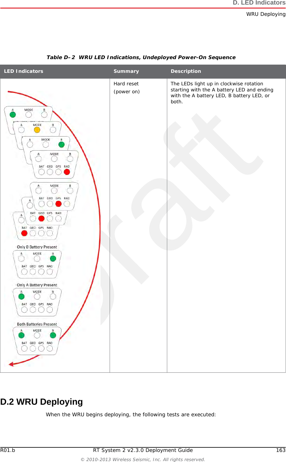
![DraftH. Country Codes188 RT System 2 v2.3.0 Deployment Guide R01.b© 2010-2013 Wireless Seismic, Inc. All rights reserved.Congo (the Democratic Republic of the) 180Cook Islands (the) 184Costa Rica 188Côte d'Ivoire 384Croatia 191Cuba 192Curaçao 531Cyprus 196Czech Republic (the) 203Denmark 208Djibouti 262Dominica 212Dominican Republic (the) 214Ecuador 218Egypt 818El Salvador 222Equatorial Guinea 226Eritrea 232Estonia 233Ethiopia 231Falkland Islands (the) [Malvinas] 238Faroe Islands (the) 234Fiji 242Finland 246France 250French Guiana 254French Polynesia 258French Southern Territories (the) 260Gabon 266Gambia (The) 270Table H–1 ISO 3166 Country CodesName CodeGeorgia 268Germany 276Ghana 288Gibraltar 292Greece 300Greenland 304Grenada 308Guadeloupe 312Guam 316Guatemala 320Guernsey 831Guinea 324Guinea-Bissau 624Guyana 328Haiti 332Heard Island and McDonald Islands 334Holy See (the) [Vatican City State] 336Honduras 340Hong Kong 344Hungary 348Iceland 352India 356Indonesia 360Iran (the Islamic Republic of) 364Iraq 368Ireland 372Isle of Man 833Israel 376Italy 380Jamaica 388Table H–1 ISO 3166 Country CodesName Code](https://usermanual.wiki/Wireless-Seismic/00104.Users-Manual-Rev-1-Part-2-of-2/User-Guide-2154857-Page-88.png)