Wireless Seismic 00104 Wireless Seismic Sensor User Manual DeploymentGuide
Wireless Seismic, Inc. Wireless Seismic Sensor DeploymentGuide
Contents
- 1. Users Manual Rev 1 Part 1 of 2
- 2. Users Manual Rev 1 Part 2 of 2
Users Manual Rev 1 Part 2 of 2
Draft
102 RT System 2 v2.3.0 Deployment Guide R01.b
© 2010-2013 Wireless Seismic, Inc. All rights reserved.
5. Point-to-Multipoint Backhaul
Preparation
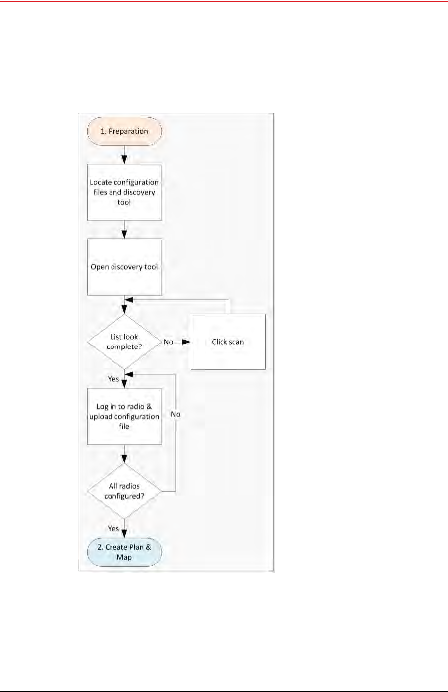
5.2 Preparation
This section provides the steps required to prepare the radios for placement in the field.
Figure 5–6 Preparation Troubleshooting Flow
Draft
R01.b RT System 2 v2.3.0 Deployment Guide 103
© 2010-2013 Wireless Seismic, Inc. All rights reserved.
5. Point-to-Multipoint Backhaul
Preparation
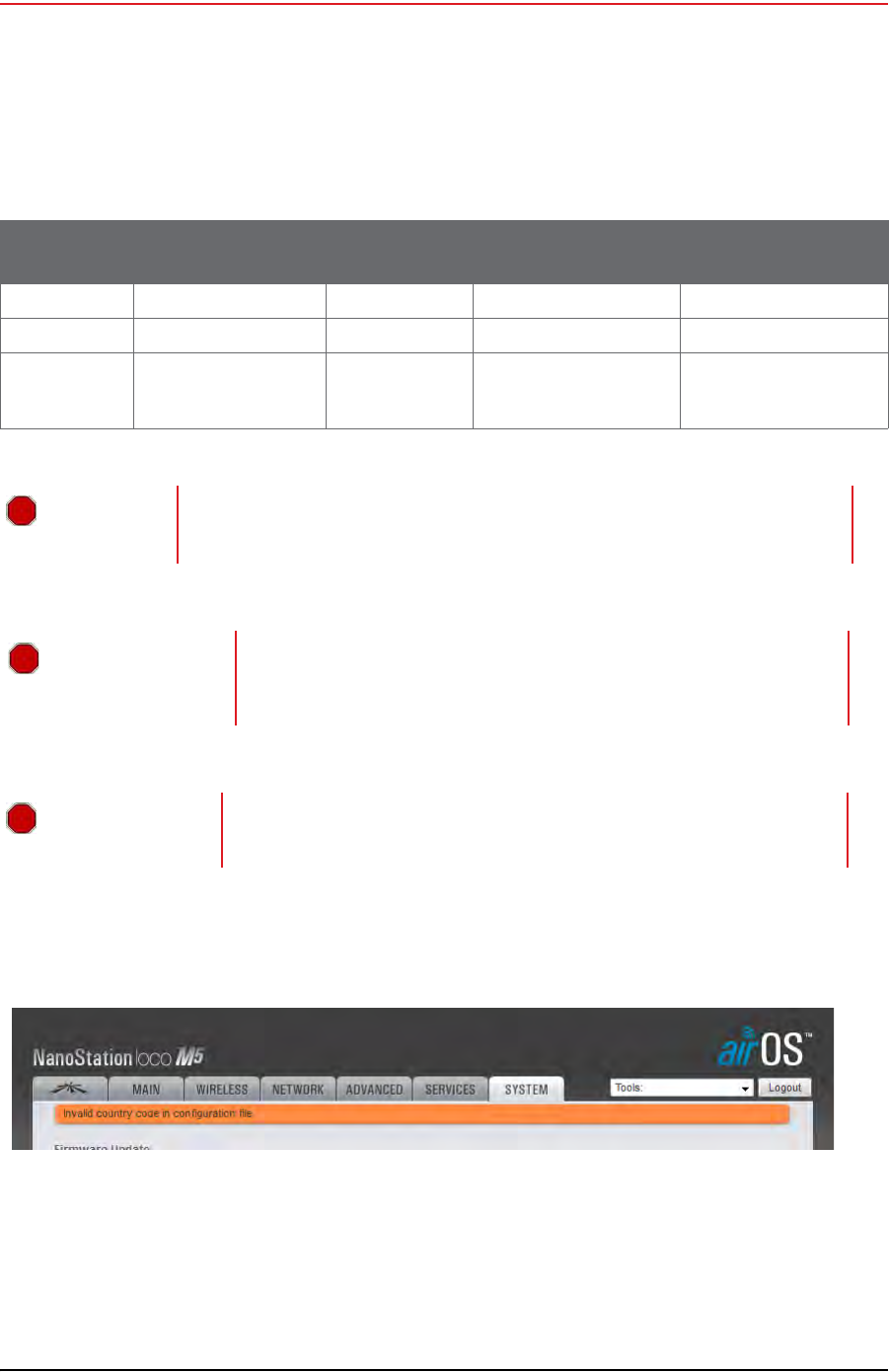
There are two versions of the radios. one for use in the United States of America and
Canada, and one for use internationally. Verify that you are using the correct radio and
configuration files for your location.
If you use an international configuration file with a United States radio, or a United States
configuration file with an international radio, an error message is displayed:
Table 5–1 Supported Backhaul Radios
Radio Antenna Use For US
5745 - 5825 MHz INTL
5470 - 5825 MHz
Rocket External Omni Recorder 15-0052 15-0054
Bullet External Directional Line Station 56-0019 56-0024
NanoStation Internal Directional Recorder
-or-
Line Station
56-0035 56-0032
WARNING
WARNING
Operating outside of the allowed frequency range could result in sanctions by
governmental regulatory agencies. Verify that all radios are correct for the
market in which they will be used.
AVERTISSEMENT
Le fait de faire marcher à l'extérieur de la bande de fréquences permise
pourrait s'ensuivre dans les sanctions par les agences gouvernementales
de contrôle. Vérifiez que toutes les radios sont correctes pour le marché
dans lequel ils seront utilisés.
OSTRZEŻENIE
Działających poza zakres częstotliwości dozwolonych może skutkować
sankcjami przez rządowe agencje regulacyjne. Sprawdź, czy wszystkie
radia są poprawne dla rynku, w którym będą one wykorzystywane.
Figure 5–7 Invalid Country Code Error Message

Draft
104 RT System 2 v2.3.0 Deployment Guide R01.b
© 2010-2013 Wireless Seismic, Inc. All rights reserved.
5. Point-to-Multipoint Backhaul
Preparation
To discover and configure the radios:
→RT System 2 Windows computer
1Verify that the configuration files for the radios and the discovery tool are on the RT
System 2 Windows computer. The configuration files and the Ubiquiti Discovery Tool
files are provided as a ZIP file. Extract the files if necessary.
The following table provides example file names for the common installation
configurations. The files provided to you may have a different naming convention based
on the specific job requirements; however, there will be one or more configuration files
for the recorder radios and one or more configuration files for the line station radios:
TIP
Country codes are three-digit codes defined in ISO 3166-1. See the following link
for more information:
http://www.iso.org/iso/home/standards/country_codes.htm
See “H. Country Codes” on page 187 for a list of codes.
TIP
Use a Rocket radio at the recording truck in the following cases:
• You need an omni-directional antenna
–or–
• Bullet radios are used at the line stations
Use a NanoStation radio at the recording truck when you need a directional
antenna.
Table 5–2 Example File Names
Standard
Configuration Redundant
Configuration Custom Configuration
RECORDER_A.cfg RECORDER_A.cfg RECORDER_A.cfg
LINE_RADIO_1.cfg RECORDER_B.cfg RECORDER_B.cfg
LINE_RADIO_2.cfg LINE_RADIO_1.cfg RECORDER_C.cfg
LINE_RADIO_3.cfg LINE_RADIO_2.cfg LINE_RADIO_1_RECORDER_A.cfg
LINE_RADIO_4.cfg LINE_RADIO_3.cfg LINE_RADIO_2_RECORDER_B.cfg
LINE_RADIO_5.cfg LINE_RADIO_4.cfg LINE_RADIO_3_RECORDER_C.cfg
LINE_RADIO_6.cfg LINE_RADIO_5.cfg LINE_RADIO_4_RECORDER_A.cfg
LINE_RADIO_7.cfg LINE_RADIO_6.cfg LINE_RADIO_5_RECORDER_B.cfg
LINE_RADIO_8.cfg LINE_RADIO_7.cfg LINE_RADIO_6_RECORDER_C.cfg
Draft
R01.b RT System 2 v2.3.0 Deployment Guide 105
© 2010-2013 Wireless Seismic, Inc. All rights reserved.
5. Point-to-Multipoint Backhaul
Preparation
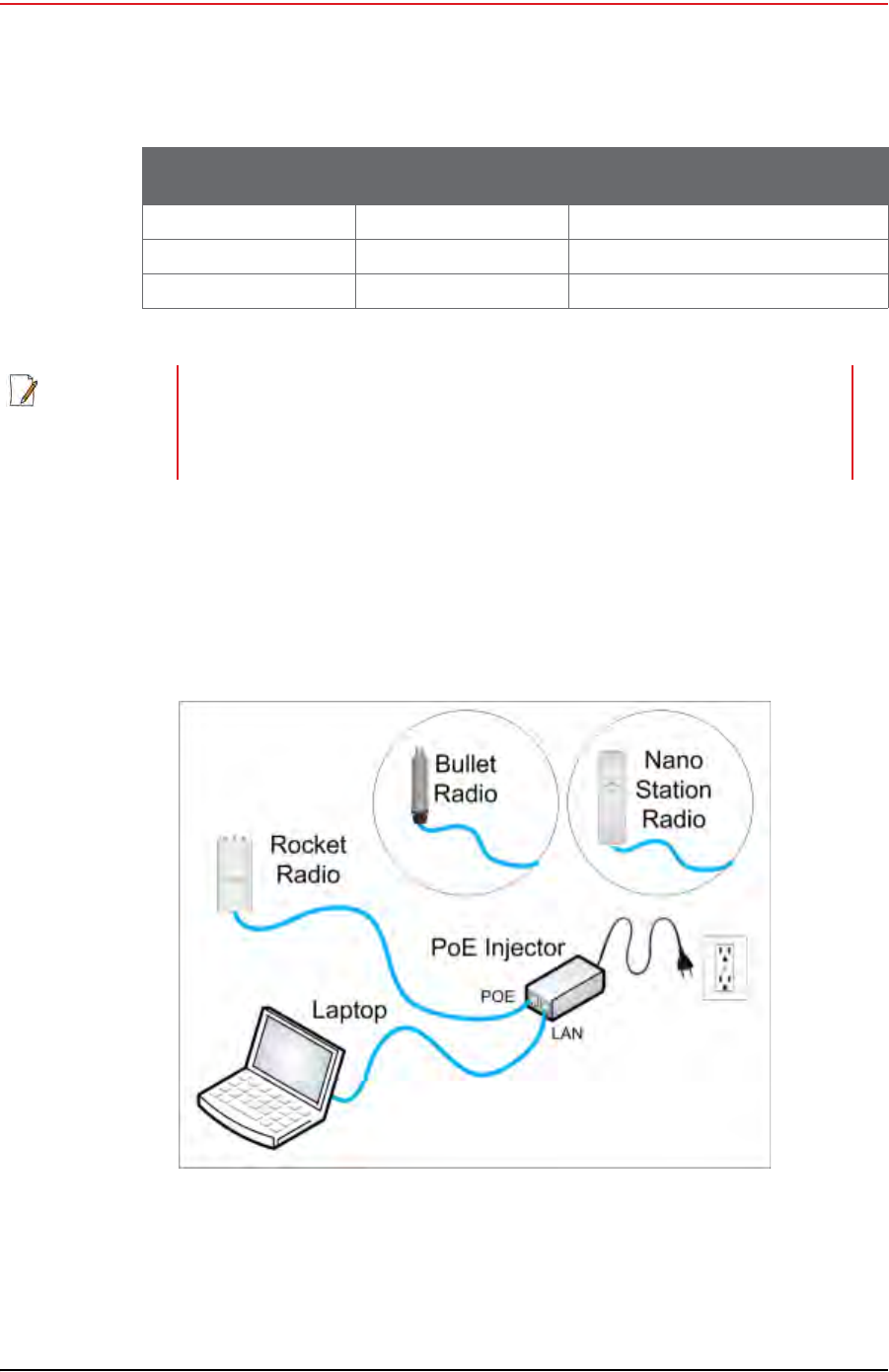
2Configure the computer to be a private network with a static IP address of
192.168.1.100. See the Troubleshooting Guide, Additional Information chapter,
Setting a Static IP Address section if you need instructions on setting the IP address
(Control Panel → Network and Internet → Network and Sharing → Change
adapter settings → LAN → Properties → IPv4 → Properties).
3Connect a single radio to the computer.
4Open the Ubiquiti Discovery Tool by double-clicking the shortcut on the desktop.
LINE_RADIO_9.cfg LINE_RADIO_8.cfg LINE_RADIO_7_RECORDER_A.cfg
LINE_RADIO_10.cfg LINE_RADIO_9.cfg LINE_RADIO_8_RECORDER_B.cfg
LINE_RADIO_11.cfg LINE_RADIO_10.cfg LINE_RADIO_9_RECORDER_C.cfg
NOTE
When using a radio link (pendant) to the recording truck, the following
configuration files are also required:
• Recorder-AP.cfg
•Recorder-S.cfg
Figure 5–8 Ubiquiti Rocket/Bullet Private Network Connection
Table 5–2 Example File Names
Standard
Configuration Redundant
Configuration Custom Configuration

Draft
106 RT System 2 v2.3.0 Deployment Guide R01.b
© 2010-2013 Wireless Seismic, Inc. All rights reserved.
5. Point-to-Multipoint Backhaul
Preparation
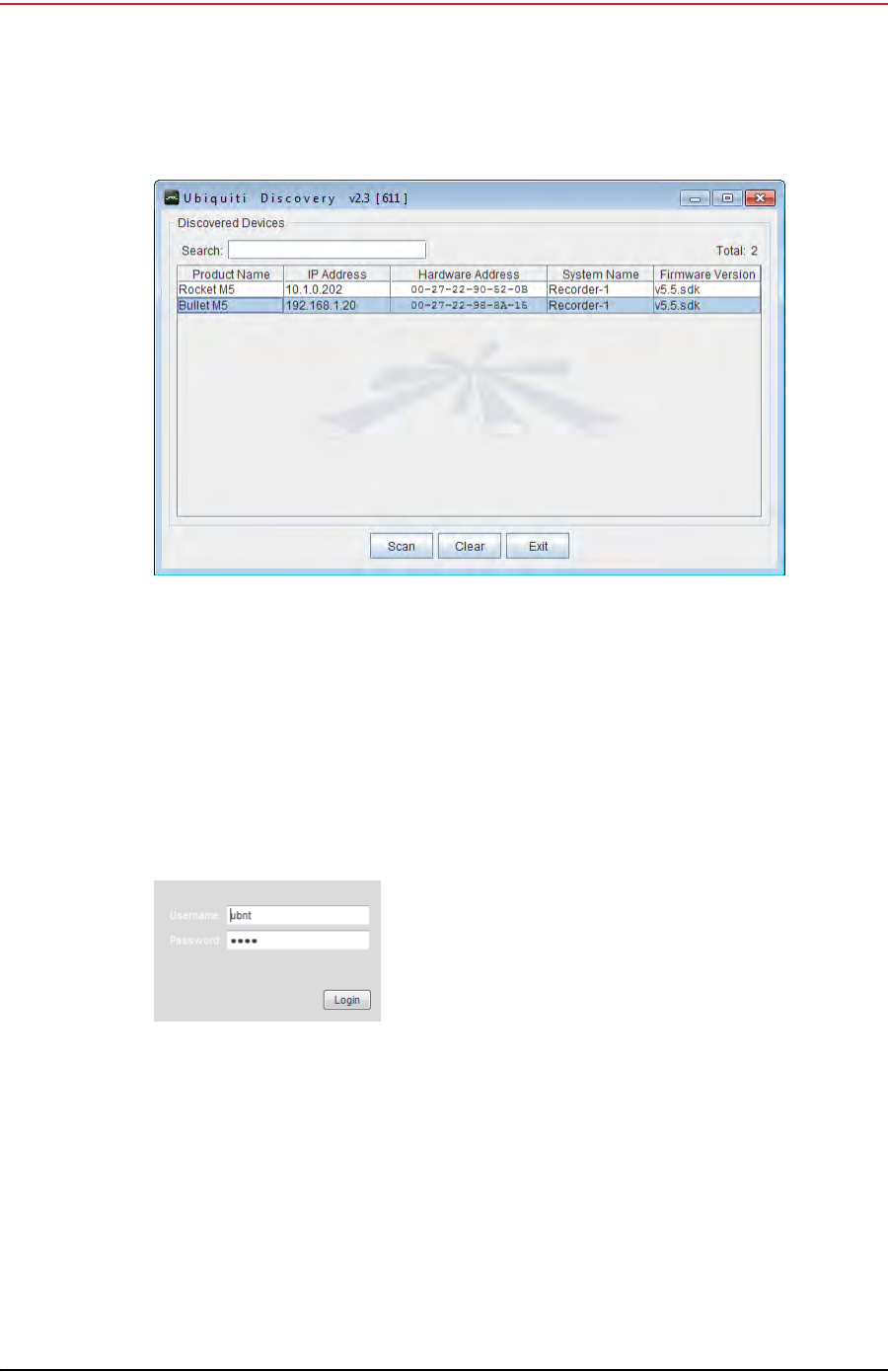
5The Discovery window opens and displays a list of all Discovered Devices:
Figure 5–9 Ubiquiti
Discovery Tool Icon
TIP
Ensure that the .bat file and the .jar file are in the same directory.
NOTE
The discovery tool can also be downloaded from the following location:
http://www.ubnt.com/download#app
Extract the files from the downloaded ZIP file to the desktop.
NOTE
The factory default IP address for the radios is 192.168.1.20. Configure the
radios one at a time.
Draft
R01.b RT System 2 v2.3.0 Deployment Guide 107
© 2010-2013 Wireless Seismic, Inc. All rights reserved.
5. Point-to-Multipoint Backhaul
Preparation
6If the list does not look correct, click Scan.
7Right-click one of the radios and then click Web UI. For example, right-click the
following row:
Bullet M5 | 192.168.1.20 | 00-27-22-98-8A-15 | Recorder-1
and then click Web UI. The airOS login window opens:
8Type the following credentials and click Login:
●Username: ubnt
●Password: ubnt
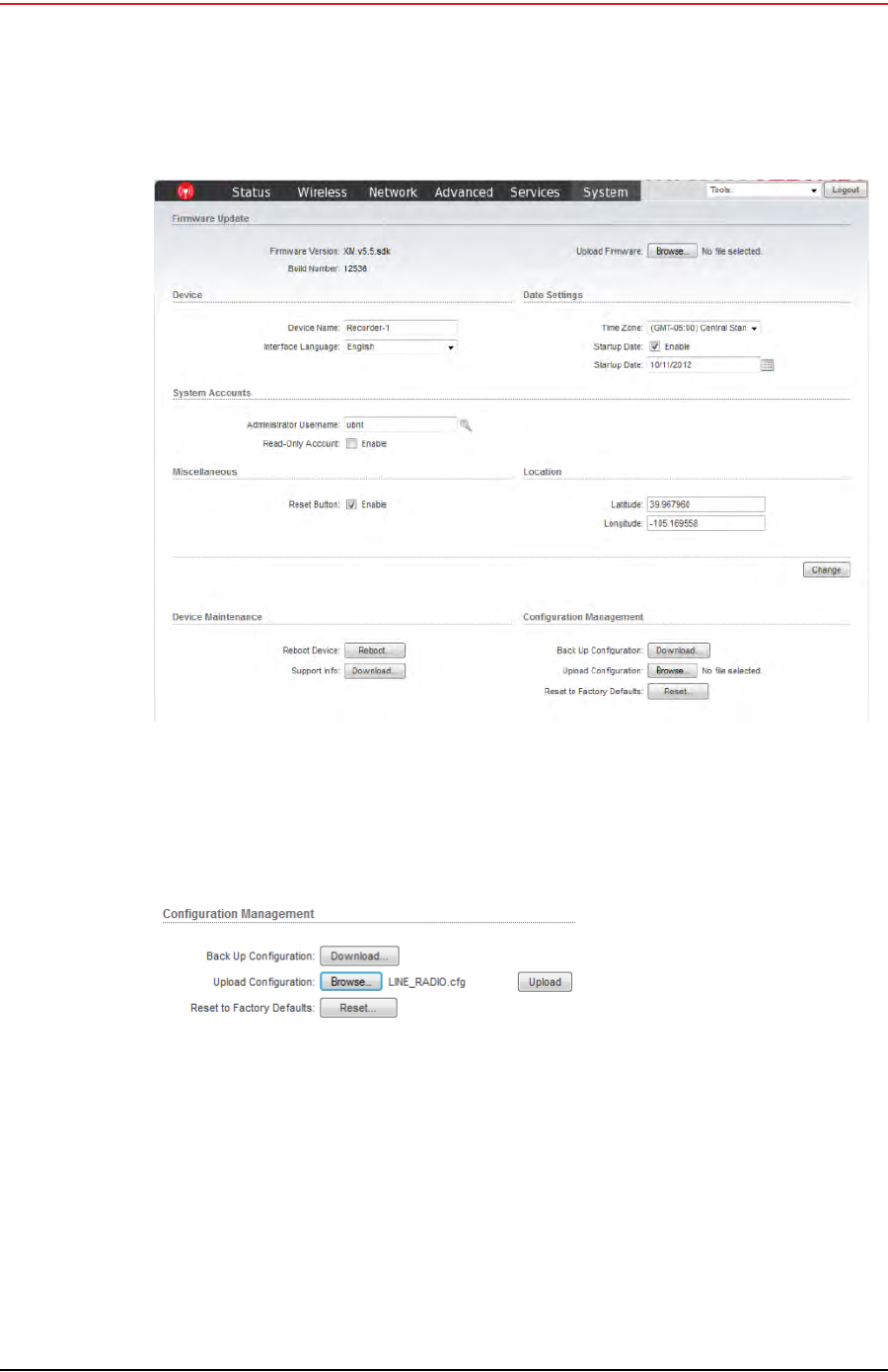
9The radio configuration window opens. Click the System tab.
Figure 5–10 Ubiquiti Discovery Window
Figure 5–11 Ubiquiti Login
Window
Draft
108 RT System 2 v2.3.0 Deployment Guide R01.b
© 2010-2013 Wireless Seismic, Inc. All rights reserved.
5. Point-to-Multipoint Backhaul
Preparation
10 In the Device Maintenance → Upload Configuration area, click Browse. Browse to
the configuration file (for example LINE_RADIO_1.cfg), and then click Upload.
11 Click Apply.
Figure 5–12 Ubiquiti Rocket/Bullet Window, System Tab
Figure 5–13 Upload Configuration File
Draft
R01.b RT System 2 v2.3.0 Deployment Guide 109
© 2010-2013 Wireless Seismic, Inc. All rights reserved.
5. Point-to-Multipoint Backhaul
Create Plan and Map
12 The radio reboots and obtains a new IP address if a DHCP server is active. The current
session of airOS is no longer valid since the IP address of the radio has changed.
13 Close the browser window.
14 Disconnect the radio. It is now ready for deployment.
15 Continue connecting radios and uploading configuration files until they are all
configured.
16 Configure a second recorder radio (RECORDER_B) if you are creating a redundant setup.
17 Configure any backup recorder radios if required.
5.3 Create Plan and Map
Using the documents provided for the job (survey, planned LIU locations, and so on), create
a plan to plot radio locations and map the layout of the radios.
Keep the following in mind as you create the layout plan:
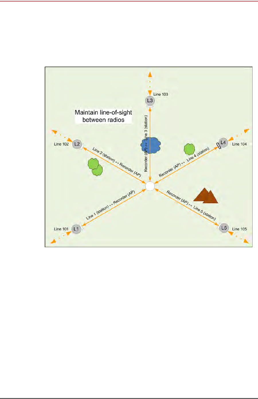
Point the radio pairs directly at each other whenever possible maintaining line-of-sight
around obstructions (see “Maintain Line-of-Sight” on page 110).
Use a tool such as Google Earth or Global Mapper to create an Elevation Profile to assist
with determining the best locations for radio towers. See “Creating a Google Earth
Elevation Profile” on page 111 for an example.
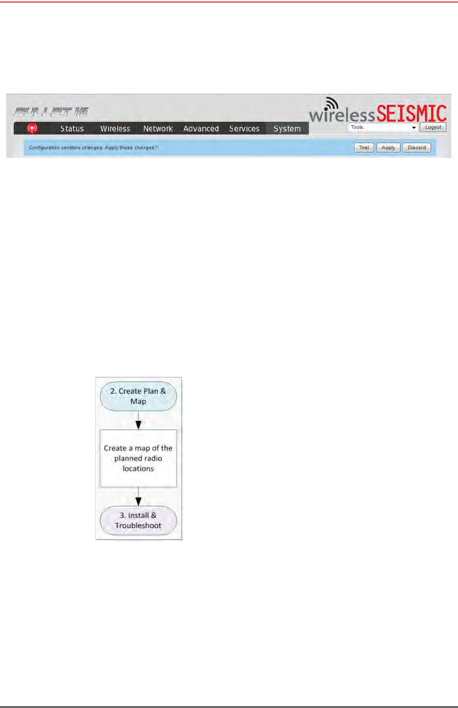
Figure 5–14 System Tab, Apply Changes
Figure 5–15 Create Plan and
Map Troubleshooting Flow
Draft
110 RT System 2 v2.3.0 Deployment Guide R01.b
© 2010-2013 Wireless Seismic, Inc. All rights reserved.
5. Point-to-Multipoint Backhaul
Create Plan and Map
An Access Point communicates only with a Station. An Access Point cannot communicate
with an Access Point, and a Station cannot communicate with a Station.
Figure 5–16 Maintain Line-of-Sight
Draft
R01.b RT System 2 v2.3.0 Deployment Guide 111
© 2010-2013 Wireless Seismic, Inc. All rights reserved.
5. Point-to-Multipoint Backhaul
Create Plan and Map
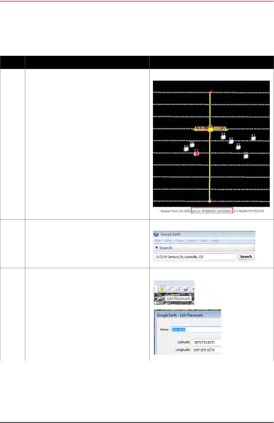
Table 5–3 Creating a Google Earth Elevation Profile
Step Instructions Example Image
1 In the RT System 2 Spread Manager, make a note
of the Lat/Lon coordinates for the starting and
ending point of the planned backhaul.
For example:
• Line101, Receiver Point 1030
Lat/Lon = 39.9660626/-105.1693101
• Line 110, Receiver Point 1030
Lat/Lon = 39.9701155/-105.1692904
2 Open Google Earth and navigate to your survey
location. For example, type an address or Lat/Lon
coordinates in the text box and then click Search.
3 Add a placemark for the beginning and ending
points of the planned backhaul.
•Click Add Placemark.
•Type a Name, Latitude, and Longitude. The
decimal value entered is automatically
converted to degrees/minutes/seconds.
•Click OK.
Draft
112 RT System 2 v2.3.0 Deployment Guide R01.b
© 2010-2013 Wireless Seismic, Inc. All rights reserved.
5. Point-to-Multipoint Backhaul
Create Plan and Map
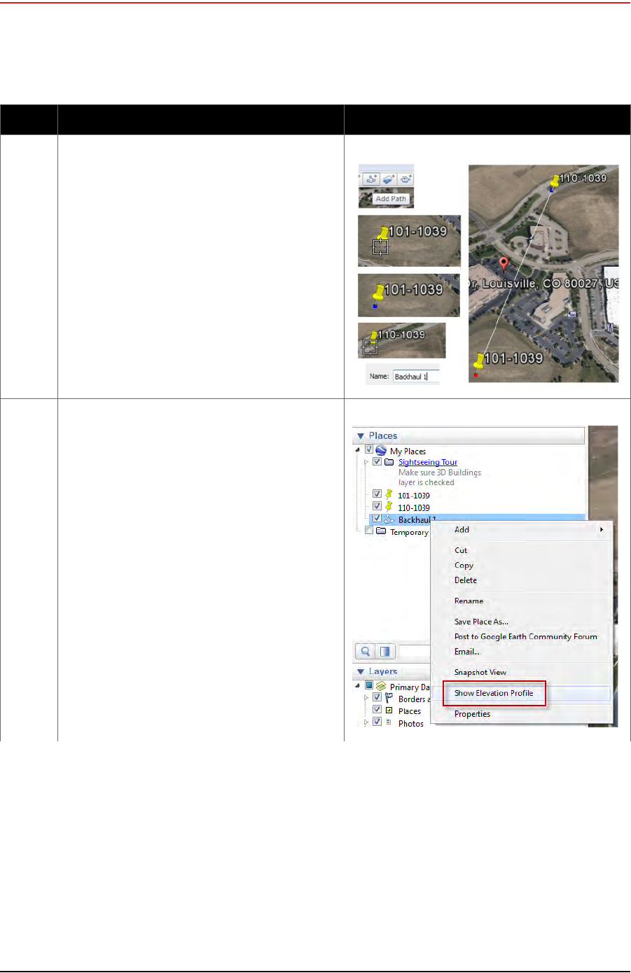
4 Add a path between the placemarks.
•Click Add Path
• Click the first placemark.
• Click the second placemark. A line is drawn
between the two placemarks.
•Type a Name and then click OK.
5 Right-click the saved path and then click Show
Elevation Profile.
Table 5–3 Creating a Google Earth Elevation Profile (cont.)
Step Instructions Example Image
Draft
R01.b RT System 2 v2.3.0 Deployment Guide 113
© 2010-2013 Wireless Seismic, Inc. All rights reserved.
5. Point-to-Multipoint Backhaul
Install and Troubleshoot
5.4 Install and Troubleshoot
This section describes how to install the radios and troubleshoot the radio communications.
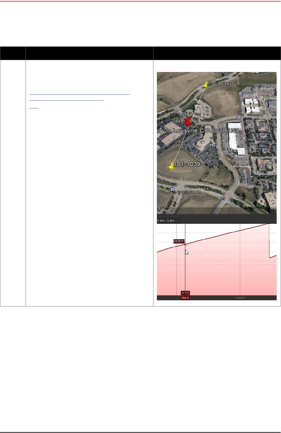
6 Refer to the elevations and numbers displayed
when planning the tower locations and heights.
See the following link for more assistance in
creating and using Google Earth Elevation Profiles.
https://support.google.com/earth/answer/
181393?hl=en&ref_topic=2376
756
Table 5–3 Creating a Google Earth Elevation Profile (cont.)
Step Instructions Example Image

Draft
114 RT System 2 v2.3.0 Deployment Guide R01.b
© 2010-2013 Wireless Seismic, Inc. All rights reserved.
5. Point-to-Multipoint Backhaul
Install and Troubleshoot
Figure 5–17 Install and Troubleshoot the Radios Flow

Draft
R01.b RT System 2 v2.3.0 Deployment Guide 115
© 2010-2013 Wireless Seismic, Inc. All rights reserved.
5. Point-to-Multipoint Backhaul
Install and Troubleshoot
5.4.1 Using one Recorder Radio
This section describes how the steps to configure one recorder radio, and multiple line station
radios.
To install and troubleshoot the radios:
1Using the plan created in “Create Plan and Map” on page 109, install all of the radios,
masts, and LIUs. Point radio pairs directly at each other where possible (see “Maintain
Line-of-Sight” on page 110). Some inaccuracy is tolerable; however, align the radios as
close as possible using binoculars or compass bearing.
2If your configuration includes a redundant recorder radio, do not supply power to it yet
(RECORDER_B).
3From the recording truck, open the Ubiquiti Discovery Tool. Verify that all of the radios
are listed, and verify that each of the radios has a valid IP Address. Note the following:
●If a radio is listed, that means there is an Ethernet path to the radio.
●If a line station radio has a valid IP address that means the DHCP is active, DHCP is
being accepted by the radios, and DHCP is being passed from the recorder radio.
►DHCP server-assigned IP addresses are 10.xxx.xxx.xxx
►Non-DHCP server-assigned IP addresses are 192.168.1.xxx
4If the recorder radio is the only radio listed, the problem is probably at the recorder
radio. Perform the following steps:
aVerify that the recorder radio is connected to the antenna.
bVerify that the antenna mast is elevated to the correct height
cVerify that the recorder radio has DHCP by validating the IP address displayed in the
Ubiquiti Discovery tool. It should not be 192.168.1.20 (factory default). If it is
192.168.1.20, contact Wireless Seismic for DHCP support.
dReload the configuration file on the recorder radio.
eIf the recorder radio is still the only radio listed, proceed to the line station radios.
5If a line station radio is not listed, send a troubleshooter to the radio that is not listed
and perform the following steps:
aVerify that the line station radio is securely connected to the LIU with a known-good
cable.
bVerify that the LIU has active LED lights (the battery has power).
cVerify that the LIU has a flashing LNK LED. Note the following:
►A flashing LNK LED confirms that the LIU can communicate over the network and
obtain an IP address through DHCP.
►This step helps identify the exact location in the network where communications
are broken by proving the network is active between the two radios on a specific
pole.
►If the LNK LED is not flashing, replace the Ethernet cable.
►If the LNK LED is still not flashing, replace the battery.
►If the LNK LED is still not flashing, reload the radio configuration file.
►If the LNK LED is still not flashing, replace the LIU.
dVerify that a known-good Ethernet cable is securely attached to the radio.
eConnect a laptop to the LIU.
IMPORTANT: The Ethernet ports on the LIU are PoE enabled. When connecting a
laptop computer to the LIU, use a non-powered cable (60-0039) to protect the
computer’s Ethernet port. Do not use a powered Ethernet cable (60-0054). See
“Ethernet Cable Connections Comparison” on page 116 for more information.

Draft
116 RT System 2 v2.3.0 Deployment Guide R01.b
© 2010-2013 Wireless Seismic, Inc. All rights reserved.
5. Point-to-Multipoint Backhaul
Install and Troubleshoot
fOpen the discovery tool and verify that the radio is listed. If the radio is not listed,
perform the following steps.
1) Verify that the radio has power by visually inspecting the LEDs.
2) If the radio has power but is not visible to the laptop, replace the radio.
3) If the radio does not have power, replace the cable and/or the radio.
gVerify that the line station radio is pointed in the direction of the recorder radio and
has reasonable line-of-sight (see “Maintain Line-of-Sight” on page 110).
hIf the line station radio still cannot be seen, replace the radio.
The following table compares the powered Ethernet cable and the non-powered Ethernet
cable:
5.4.2 Using a Redundant Recorder Radio
This section describes the additional steps required to configure a redundant recorder radio.
To install and troubleshoot the redundant recorder radio:
1Correctly configure the backhaul for RECORDER_A as detailed in “Using one Recorder
Radio” on page 115.
2Supply power to the RECORDER_B radio.
Table 5–4 Ethernet Cable Connections Comparison
60-0039 LIU to Computer Signal Name 60-0054 LIU to Radio PoE
14-Pin Connector RJ-45 Connector RJ-45 Connector 11-Pin Connector
B1TX+1B
A2TX-2A
C3RX+3C
NC 4 POSITIVE 4 H
NC 5 POSITIVE 5 F
D6RX-6D
NC 7 RETURN 7 E
NC 8 RETURN 8 L
P — SHIELD DRAIN — P
———NCR*
———NCM*
— *Jumper pins R and M together.

Draft
R01.b RT System 2 v2.3.0 Deployment Guide 117
© 2010-2013 Wireless Seismic, Inc. All rights reserved.
5. Point-to-Multipoint Backhaul
Final Communication Test
3Wait 2 minutes to confirm that RECORDER_B completes its boot cycle.
4Disconnect RECORDER_A.
5Verify that all line station radios are listed in the Discovery window through RECORDER_B
within 2 minutes. The typical switch over takes 30 seconds but it can take longer.
6Supply power to RECORDER_A and disconnect power from RECORDER_B.
7Verify that all line station radios are listed in the Discovery window through
RECORDER_A.
8Supply power to RECORDER_B.
9Verify that all line station radios are listed in the Discovery window.
10 Verify that both recorder radios are listed in the Discovery window.
5.4.3 Using a Custom Configuration
Custom configurations may have a number of recorder radios and line station radios.
Correctly configure the backhaul for one of the recorders, for example, RECORDER_A, as
detailed in “Using one Recorder Radio” on page 115.
Then, configure the backhaul for each additional recorder, for example, RECORDER_B, until
the backhaul configuration is complete.
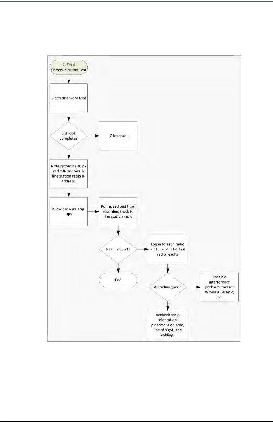
5.5 Final Communication Test
This section describes how to run the final speed test to verify good communication
throughout the backhaul. The final communication test should be run from each recorder
radio that will be communicating to line radios during production.
NOTE
Remove power from competing recorder radios during the configuration process.
During production is the only time more than one recorder radio should have
power applied.
Draft
118 RT System 2 v2.3.0 Deployment Guide R01.b
© 2010-2013 Wireless Seismic, Inc. All rights reserved.
5. Point-to-Multipoint Backhaul
Final Communication Test
To run the speed test:
1Verify that all radios are listed in the Ubiquiti Discovery Tool as described in step 3 on
page 115 through step 5 on page 115
Figure 5–18 Final Communication Test Flow
Draft
R01.b RT System 2 v2.3.0 Deployment Guide 119
© 2010-2013 Wireless Seismic, Inc. All rights reserved.
5. Point-to-Multipoint Backhaul
Final Communication Test
2Make a note of the line segment radio IP addresses, or keep the Discovery window open
for easy reference:
______.______.______.______
______.______.______.______
______.______.______.______
______.______.______.______
3The speed test should be run from the recording truck radio to the line segment radios.
Log in to the recording truck radio as described in step 2 on page 105 through step 8 on
page 107.
4Verify that browser pop-ups are allowed:
►Firefox – Tools → Options → Content → clear the Block pop-up
windows check box →click OK
►Internet Explorer – Tools → Internet Options → Privacy → clear the
Turn on Pop-up Blocker check box → click OK
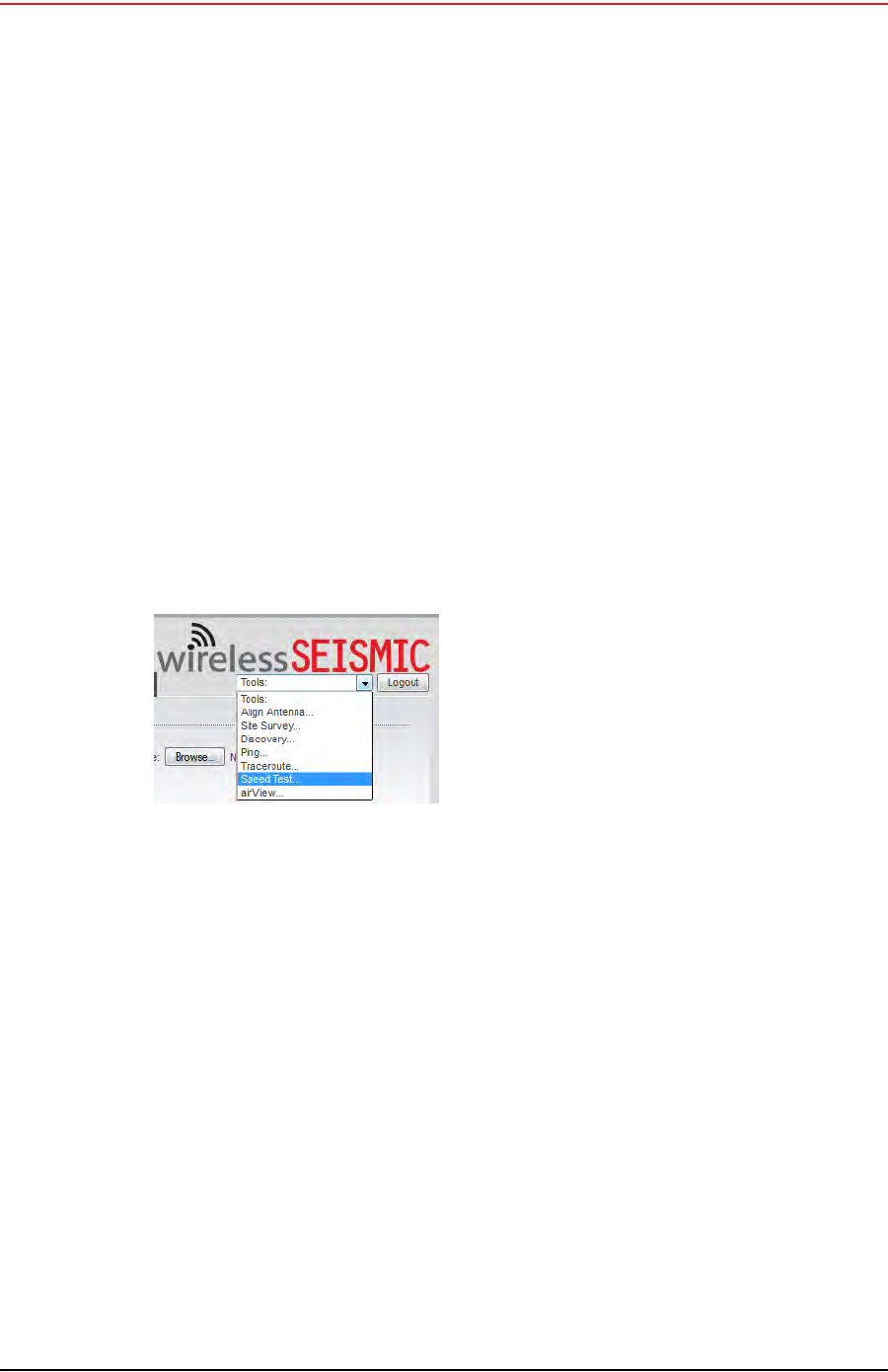
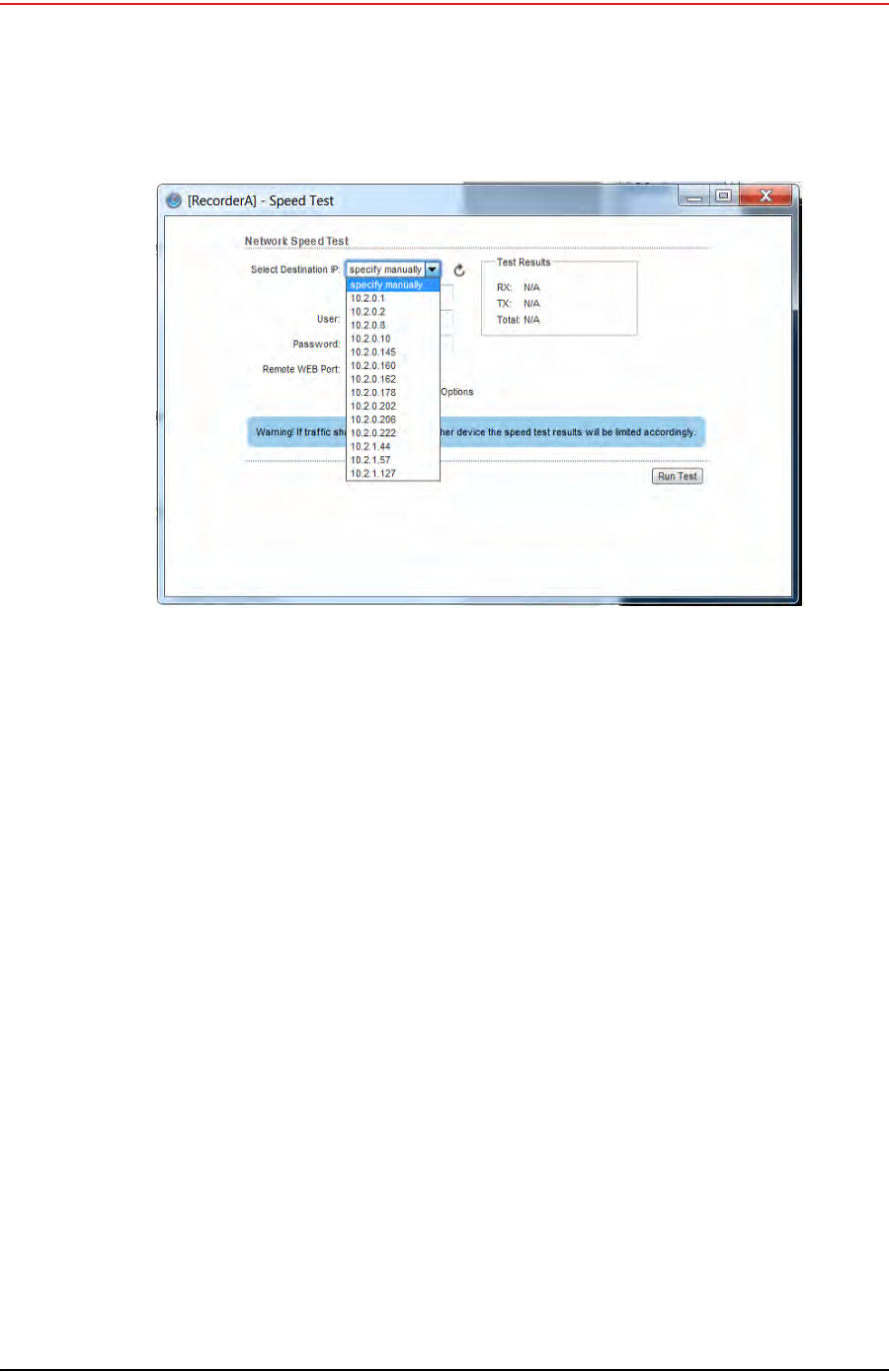
5Click Tools → Speed Test.
6In the Speed Test window, perform the following steps:
aClick the IP address for a line segment radio in the Select Destination IP list:
Figure 5–19 Tools, Speed Test
Draft
120 RT System 2 v2.3.0 Deployment Guide R01.b
© 2010-2013 Wireless Seismic, Inc. All rights reserved.
5. Point-to-Multipoint Backhaul
Final Communication Test
bType ubnt in the User text box.
cType ubnt in the Password text box.
dType 80 in the Remote WEB Port text box.
eThe default test Direction is duplex; the test is performed for both transmit and
receive. If you want to run the test in only one direction, perform the following steps:
1) Select the Show Advanced Options check box.
2) Select transmit or receive.
fClick Run Test.
gIf the following error is displayed, type 443 in the Remote WEB Port text box and
click Run Test.
Error: Invalid remote port or web server is not running.
hGood Test Results are as follows:
►RX (receive) only = 70+ Mbps
►TX (transmit) only = 70+ Mbps
►Total (duplex) = 90+ Mbps
–RX = 40+ Mbps
–TX = 40+ Mbps
7Click another line segment radio IP address in the Select Destination IP list, click Run
Test, and then check results. Repeat for all line station radios.
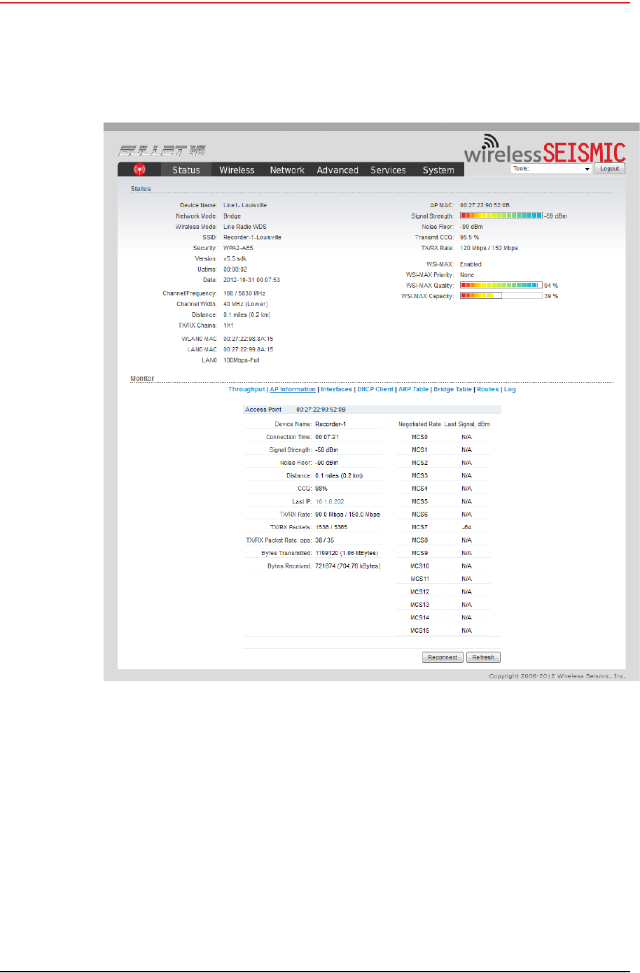
8If Speed Test results are low, perform the following steps for a Bullet radio. (Go to step
9 on page 122):
aLog in to the line station radio that displayed low Speed Test results.
bClick the Status tab and verify the following values:
►WSI-MAX (AirMax) Quality > 80%. If the value is < 80%, check the following:
Figure 5–20 Speed Test Window

Draft
R01.b RT System 2 v2.3.0 Deployment Guide 121
© 2010-2013 Wireless Seismic, Inc. All rights reserved.
5. Point-to-Multipoint Backhaul
Final Communication Test
–Poor line-of-sight
–Bad antenna connection
–Faulty hardware (cable and/or antenna)
►WSI-MAX (AirMax) Capacity >40%. If the value is < 40%, note the following:
–The maximum capacity for the titanium bullet is 50%
–Capacity is a reflection of quality. If the quality improves, the capacity
should also improve.
–Poor capacity is typically the result of a misaligned antenna.
►Click AP Information in the Monitor area. Verify that the Access Point Signal
Strength is between -80 dBm and -65 dBm.
cVerify that line station radios are pointing in the correct direction.
dRaise the mast towers to provide the least obstructed view as is reasonable.
eCheck the condition of the antenna panels.
fCheck for frayed cables or water intrusion.
Draft
122 RT System 2 v2.3.0 Deployment Guide R01.b
© 2010-2013 Wireless Seismic, Inc. All rights reserved.
5. Point-to-Multipoint Backhaul
Final Communication Test
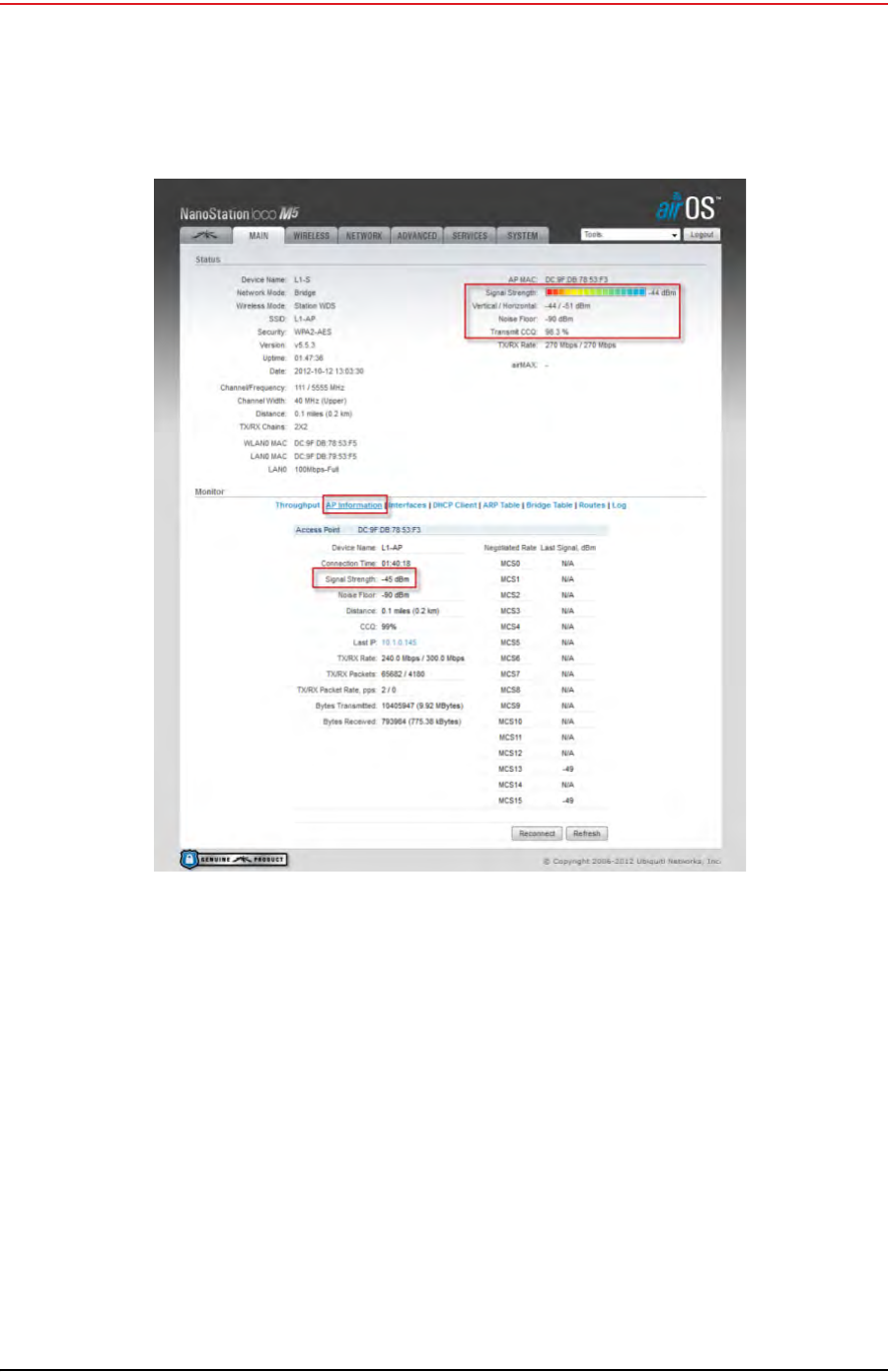
9If Speed Test results are low, perform the following steps for a NanoStation radio. Use a
systematic approach of testing links to identify the offending radio pairs:
aLog in to a Station (S) radio.
bClick the Main tab and verify the following values:
►Signal Strength < -75 dBm
►Either the Vertical or Horizontal (Main Tab, Stations only) < -80 (between -65
and -75 is ideal)
►Transmit CCQ < 90% (100% is ideal)
►Click AP Information in the Monitor area. Verify that the Access Point Signal
Strength < -75 dBm
Figure 5–21 Bullet Radio Status Tab
Draft
R01.b RT System 2 v2.3.0 Deployment Guide 123
© 2010-2013 Wireless Seismic, Inc. All rights reserved.
5. Point-to-Multipoint Backhaul
Final Communication Test
cRepeat step a and step b for all of the radios.
10 If the individual links are all good but the backhaul as a whole does not deliver the
appropriate throughput, it indicates that there is an interference problem.
Contact Andy Prokop, Jerry Stair, or Mike Shilts for project-specific recommendations.
11 If there are individual links with low numbers, perform the following steps to fix them:
aVerify that the radios are pointing in the correct directions.
bVerify that there are no frayed cables or cables with water intrusion.
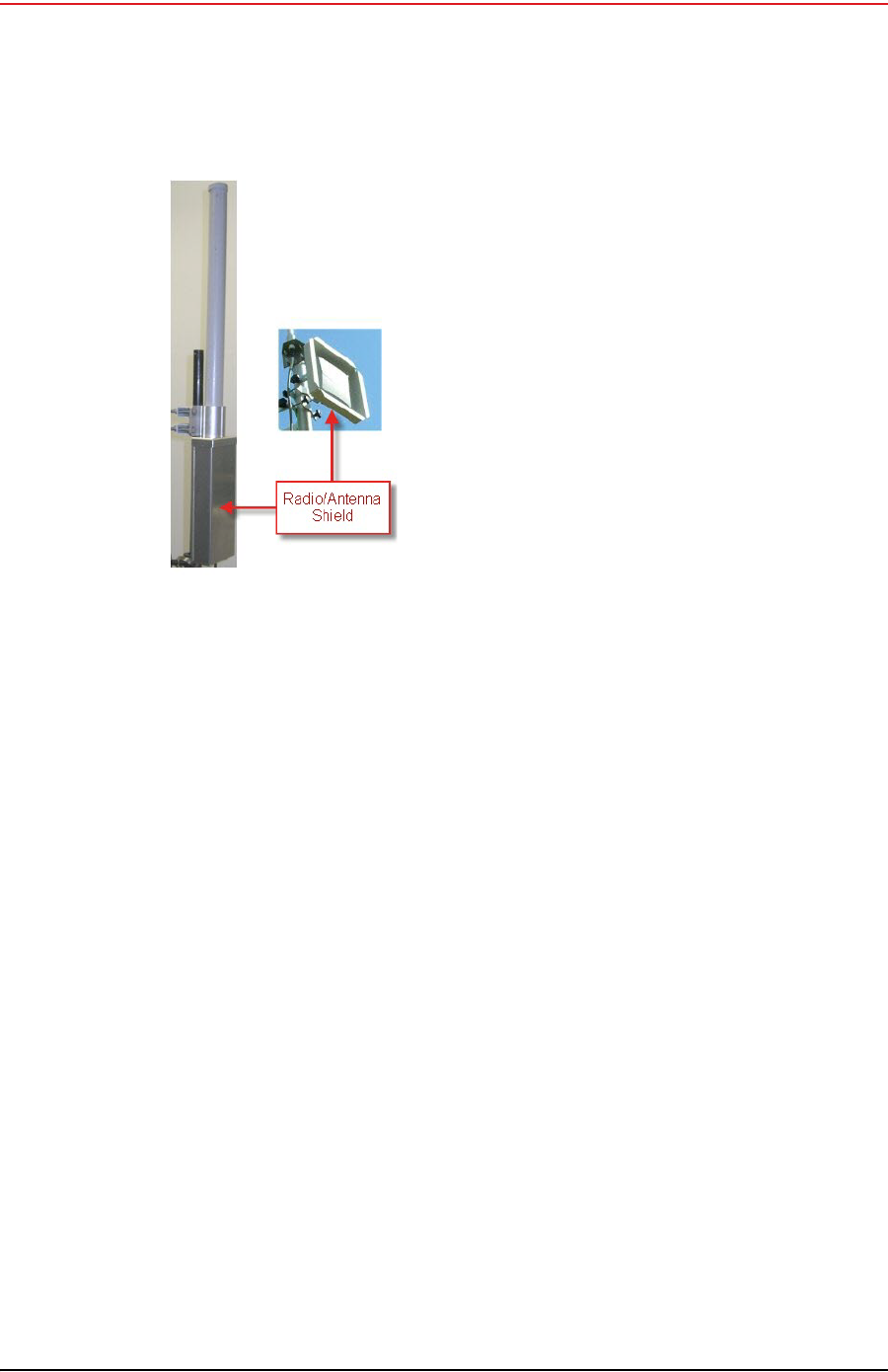
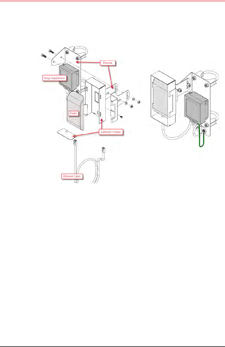
cVerify that shielding is properly installed. The following figure shows the radio/
antenna shielding:
Figure 5–22 NanoStation Main Tab
Draft
124 RT System 2 v2.3.0 Deployment Guide R01.b
© 2010-2013 Wireless Seismic, Inc. All rights reserved.
5. Point-to-Multipoint Backhaul
Final Communication Test
Figure 5–23 Radio/Antenna
Shielding
Draft
R01.b RT System 2 v2.3.0 Deployment Guide 125
© 2010-2013 Wireless Seismic, Inc. All rights reserved.
5. Point-to-Multipoint Backhaul
Replacing a Radio
dFor the NanoStation radios:
1) Verify that the radios on the same pole are at least three feet apart.
2) Verify that the Access Point (A) radio is three feet higher on the pole than the
Station (S) radio.
3) If possible, raise the poles (masts) to provide the least-obstructed view to the
partner radio as is reasonable.
5.6 Replacing a Radio
Any number of environmental hazards could destroy an existing radio. When this happens,
replace it using the following instructions:
1Identify the radio that needs to be replaced.
2When the radio was initially configured for the point-to-multipoint backhaul, a label was
attached to the radio indicating which configuration file was used. Make a note of the
configuration label (for example, Line_1_Recorder_A).
3Duplicate the configuration label and attach it to the replacement radio using the same
information.
4Locate the corresponding configuration file (for example, Line_1_Recorder_A.cfg)
and upload it to the replacement radio according to step 2 on page 105 through step 13
on page 109.
Figure 5–24 NanoStation Radio Shielding and Surge Suppressor
Draft
126 RT System 2 v2.3.0 Deployment Guide R01.b
© 2010-2013 Wireless Seismic, Inc. All rights reserved.
5. Point-to-Multipoint Backhaul
Upload New Firmware
5Mark the faulty radio is so that it does not work its way back into the spread.
6Replace the radio on the pole.
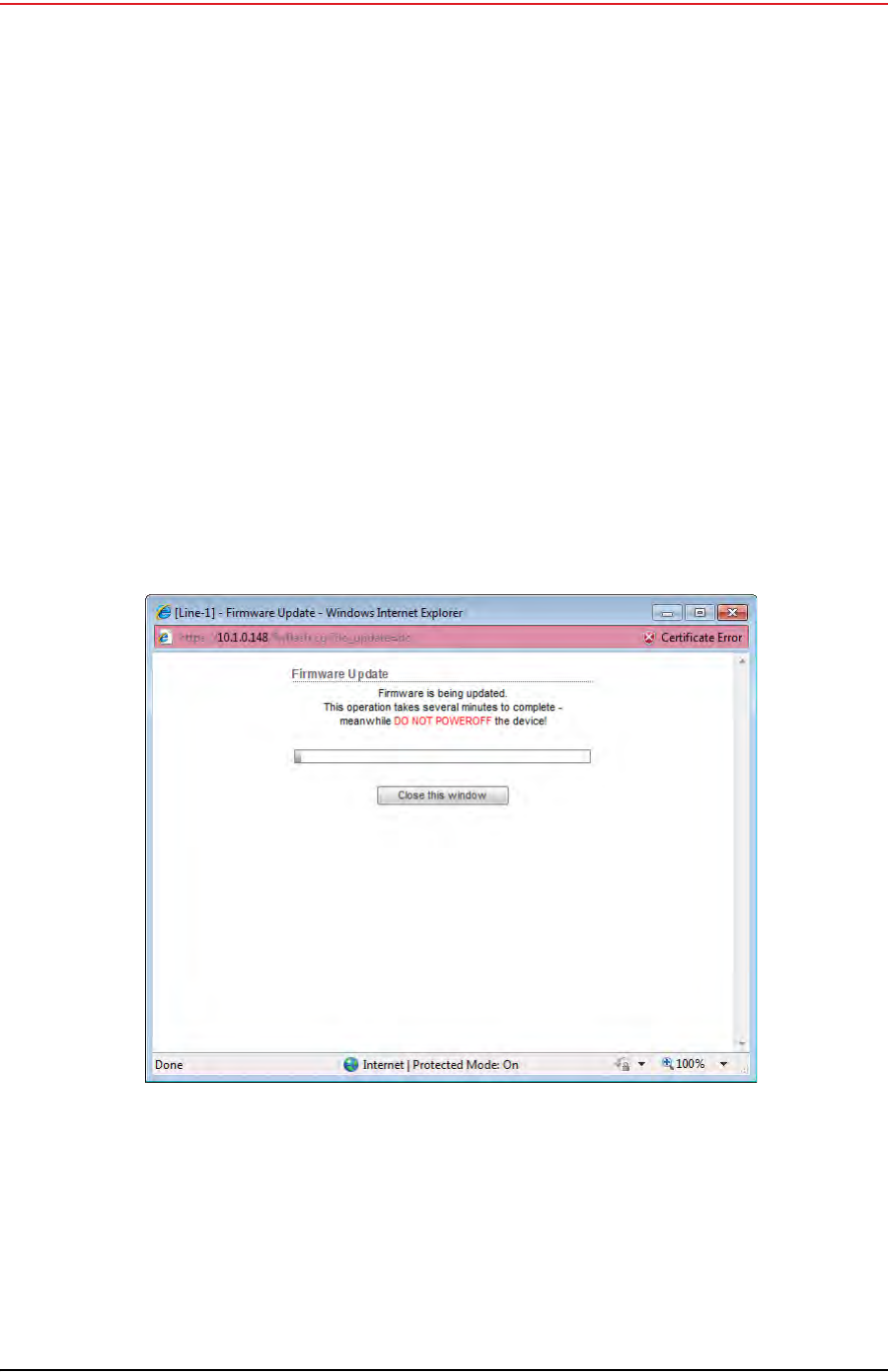
5.7 Upload New Firmware
This section describes how to upload new firmware into the radio.
To upload new firmware:
→Windows computer → Radio Configuration, System tab
1Click Browse next to Upload Firmware and navigate to the supplied BIN file.
2Select the file and click Open.
3Click Upload.
4Click Update.
5Do not power off the radio until the firmware is updated.
5.8 Unzipping the Configuration Files
The configuration files are delivered combined into one compressed file (config.zip).
Figure 5–25 Radio Configuration, Updating Firmware

Draft
R01.b RT System 2 v2.3.0 Deployment Guide 127
© 2010-2013 Wireless Seismic, Inc. All rights reserved.
5. Point-to-Multipoint Backhaul
Connecting to the Recording Truck
To extract the files, use the built-in Windows 7 extraction process, or you can use a third-
party tool such as 7-Zip.
To use the Windows 7 process:
1Locate the ZIP file in Windows Explorer.
2Right-click the ZIP file name and then click Extract All.
3Browse to and select a folder.
4Click Extract.
To use 7-Zip:
1Download and install 7-Zip if it is not already installed:
http://www.7-zip.org/download.html
2Locate the ZIP file in Windows Explorer.
3Right-click the ZIP file name and then click 7-zip → Extract Files.
4Browse to and select a folder.
5Click OK.
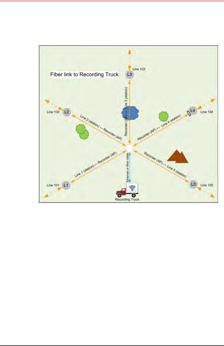
5.9 Connecting to the Recording Truck
The line communicates to the recording truck through an LIU using one of the following
methods:
Fiber cable
Radio link (pendant)
The following figure shows a fiber cable connection example:
Draft
128 RT System 2 v2.3.0 Deployment Guide R01.b
© 2010-2013 Wireless Seismic, Inc. All rights reserved.
5. Point-to-Multipoint Backhaul
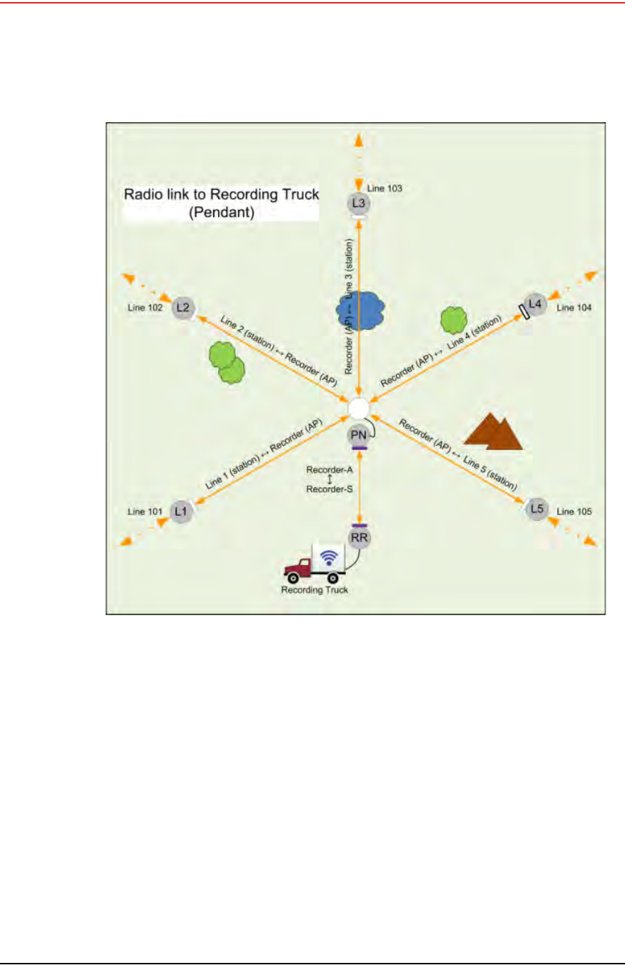
Connecting to the Recording Truck
The following figure shows a radio link (pendant) connection example.
Figure 5–26 Connecting the Recording Truck with Fiber
Draft
R01.b RT System 2 v2.3.0 Deployment Guide 129
© 2010-2013 Wireless Seismic, Inc. All rights reserved.
5. Point-to-Multipoint Backhaul
Connecting to the Recording Truck
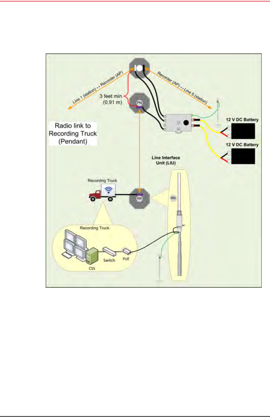
The following figure shows the connections for the pendant radio link example.
Figure 5–27 Connecting the Recording Truck with a Pendant Radio Link
Draft
130 RT System 2 v2.3.0 Deployment Guide R01.b
© 2010-2013 Wireless Seismic, Inc. All rights reserved.
5. Point-to-Multipoint Backhaul
Connecting to the Recording Truck
Figure 5–28 Connecting the Pendant Radio Link

Draft
R01.b RT System 2 v2.3.0 Deployment Guide 131
© 2010-2013 Wireless Seismic, Inc. All rights reserved.
5. Point-to-Multipoint Backhaul
Connecting to the Recording Truck
The following table lists information about the pendant radio connection.
Table 5–5 Pendant Radio Link Elements
Item Description
Configuration The following additional configuration files are provided:
• • Recorder-AP.cfg
• • Recorder-S.cfg
RR • The radio at the recording truck is a Rocket radio with an Omni
antenna and is indicated in the drawings as RR (Recorder/
Rocket).
• Use the Recorder-AP.cfg file with this radio.
• The RR radio should be installed at the top of the pole, pointing
directly at the pendant radio (PN).
PN • The radio at the line is a NanoStation radio with a built-in
antenna and is indicated in the drawings as PN (Pendant/Nano).
• Use the Recorder-S.cfg file with this radio.
• The PN radio should be installed at the top of the pole, pointing
directly at the recording truck radio antenna (RR).
• The PN radio should be at least 3 ft (0.91 m) from the line pole
(Pole 1 in the example shown in “Connecting the Recording
Truck with a Pendant Radio Link” on page 129). Use as much
distance as you can as allowed by your cable lengths.
• The PN radio and pole should be between the line and the
recording truck as shown in “Connecting the Recording Truck
with a Pendant Radio Link” on page 129.
Batteries • Adding a third radio to the LIU increases the battery usage at
this position. To ensure that the LIU does not reset due to a low
or depleted battery, keep two batteries connected to the LIU at
all times.
• The battery with the lowest voltage is used until the voltage falls
below the Unit Thresholds ? LIU Voltage Warning number
(usually about 11V). At this point, the LIU auto-swaps to the
battery with the higher voltage. Monitor the battery status in
the Ground Equipment Table. Replace the low-voltage battery
with a fully-charged battery as soon as possible after the battery
auto-swap occurs.
Draft
132 RT System 2 v2.3.0 Deployment Guide R01.b
© 2010-2013 Wireless Seismic, Inc. All rights reserved.
5. Point-to-Multipoint Backhaul
Connecting to the Recording Truck
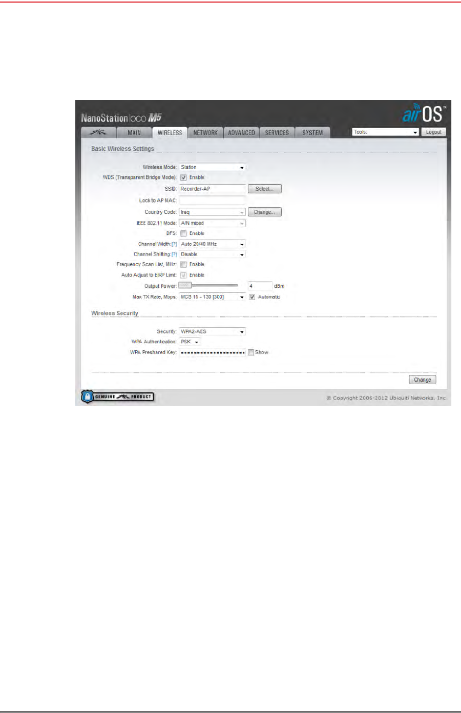
After the pendant radio link radios are configured and installed, log in to the PN radio and set
the power level to the minimum amount required to achieve communication with the RR.
To set the PN radio power level:
1Click the Wireless tab.
2Move the Output Power slider bar to the desired power level.
3Click Change at the bottom of the window.
4Click Apply Command at the top of the window.
5Wait 30 – 60 seconds.
Figure 5–29 Wireless Tab

Draft
RT System 2 v2.3.0 133 Deployment Guide R01.b
© 2010-2013 Wireless Seismic, Inc. All rights reserved.
6
6. Demobilization
6.1 Overview
This chapter describes how to prepare (undeploy) the ground electronics for transport at
the end of a project (demobilization).
6.2 Removing the WRU from the Field
This section describes the process to ready the WRU for movement to a new physical
location or to remove it in preparation for demobilization.
To undeploy the WRU:
1Prerequisites:
●The WRU is assembled with battery, geophone, and antenna (and extender)
●The WRU is in an active, transitional, or ready state
2Pick up the WRU and point the geophone connector end towards the sky as shown in
the following figure. Within a few seconds, all of the LEDs illuminate:
3Within 5 seconds, place the unit flat in the transportation vehicle as shown in the
following figure. The LEDs on the top of the unit turn off and then flash on briefly to
indicate the WRU is undeployed and the unit shuts down.
Figure 6–1 Power Off the Unit

Draft
134 RT System 2 v2.3.0 Deployment Guide R01.b
© 2010-2013 Wireless Seismic, Inc. All rights reserved.
6. Demobilization
Disassemble the WRU
4Optional: Remove batteries, antenna, or geophone as described in “Disassemble the
WRU” on page 134.
6.3 Disassemble the WRU
This section describes the process to disassemble the WRU prior to demobilization.
To disassemble the WRU:
1Undeploy the equipment as described in “Removing the WRU from the Field” on page
133.
2Remove the antenna (and extender) from the unit.
3Remove the geophone from the unit.
4Remove the batteries from the unit.
●Press the catch on the battery latch.
●Lift the lever, but do not lift the bail from the molded area on the battery.
●Continue to lift the lever using the bail to push the battery out of the connector.
Figure 6–2 Undeployed Unit

Draft
R01.b RT System 2 v2.3.0 Deployment Guide 135
© 2010-2013 Wireless Seismic, Inc. All rights reserved.
6. Demobilization
Disassemble the WRU
5Secure the equipment in the transport vehicle.
Figure 6–3 Removing the
Battery

Draft
RT System 2 v2.3.0 136 Deployment Guide R01.b
© 2010-2013 Wireless Seismic, Inc. All rights reserved.
7
7. Batteries
See “Batteries” on page 192 for the French translation of this chapter.
Voir “Batteries” sur la page 192 pour la traduction française de ce chapitre.
This chapter provides information about the batteries and battery requirements used in
the Wireless Seismic, Inc. RT System 2.
7.1 Lithium Ion Batteries
This section provides information regarding the characteristics, use, and handling of
lithium ion batteries. See the following sections for details:
“Specifications” on page 136
“Handling and Safety Guidelines” on page 137
“Transportation” on page 138
“Storage” on page 139
7.1.1 Specifications
The RT System 2 uses one or two custom intelligent lithium-ion batteries with self-
contained charging circuitry that protects the batteries from overcharge, discharge,
short circuits, or extreme temperature charging.
Battery specifications are shown in the following table:
Table 7–1 Lithium Ion Battery Specifications
Item Description Value
Voltage Nominal 3.7 VDC
Shut-off 2.8 VDC
Full (90%) charge 4.1 VDC
Overcharge Voltage 4.28 VDC
Over Discharge Voltage 2.80 VDC
Current Maximum Charge Current 2 A
Consumption Active Mode 4.2 mA maximum
Consumption Sleep Mode 66 A maximum
Full (90%) charge mAh Approximately 12,000 mAh at
nominal voltage —
Full (90%) charge mWh Approximately 44,400 mWh
at nominal voltage —
Capacity 48.8 Watt hours

Draft
R01.b RT System 2 v2.3.0 Deployment Guide 137
© 2010-2013 Wireless Seismic, Inc. All rights reserved.
7. Batteries
Lithium Ion Batteries
7.1.2 Handling and Safety Guidelines
Observe the following handling and safety guidelines:
If a battery pack has leaking fluids, do not touch any fluids. Dispose of a leaking battery
pack. In case of eye contact with fluid, do not rub eyes. Immediately flush eyes
thoroughly with water for at least 15 minutes, lifting upper and lower lids until no
evidence of the fluid remains. Seek medical attention.
Do not disassemble, crush, or puncture a battery
Do not short the external contacts on a battery
Do not dispose of a battery in fire or water
Do not expose a battery to temperatures above 60 °C (140 °F)
Keep the battery away from children
Avoid exposing the battery to excessive shock or vibration
Do not use a damaged battery
Lithium Ion battery packs MUST be completely discharged before disposal
Although there may be local or state restrictions, lithium ion batteries are considered by
the Federal Government as “non-hazardous universal waste”. There are restrictions for
large quantity handlers of universal waste that define labeling, containment, and so on.
Whenever possible the batteries must be discharged before disposal. Battery leads/
contacts should be taped off to prevent accidental shorting. Each battery pack should be
placed in a plastic bag.
Recycling is encouraged when practical and applicable. The batteries contain recyclable
material and are accepted by several battery recycling companies. Refer to one of the
following for more information on recycling and disposal:
●http://www.swe.com
Connector 5-pin —
LED One LED that indicates
charging status when
connected to the charging
station as follows
• Green – Charged
• Red – Charging
• Amber – Transitional
phase between charging
and charged, or charge
temperature limits
exceeded
Label One bar code serial number
label —
Temperature Operating From -40°C to +85°C
Charging From -5°Cto+45°C
Ambient Storage • From -20°C to +45°C for
a maximum period of one
month
• From -20°C to +35°C for
a maximum of 6 months,
after which time the
battery packs will need to
be recharged to above
50% capacity
Table 7–1 Lithium Ion Battery Specifications (cont.)
Item Description Value

Draft
138 RT System 2 v2.3.0 Deployment Guide R01.b
© 2010-2013 Wireless Seismic, Inc. All rights reserved.
7. Batteries
Lithium Ion Batteries
●http://www.rbrc.org
●http://www.call2recycle.org
●1-800-8-BATTERY
●1-877-2-RECYCLE
7.1.3 Transportation
In the United States, large lithium ion battery shipments (more than 24 cells or 12 batteries
per package) are regulated as hazardous material (Class 9) by the Federal Government and
are subject to the regulations described in the following:
Code of Federal Regulations, Title 49 Transportation
http://ecfr.gpoaccess.gov/cgi/t/text/text-
idx?sid=92868a82add6feba6afa796572133179&c=ecfr&tpl=/ecfrbrowse/Title49/
49tab_02.tpl
International Air Transport Association (IATA)
http://www.iata.org/whatwedo/cargo/dangerous_goods/pages/lithium_batteries.aspx
Batteries can be ground shipped only if all of the following conditions are met:
Box used meets the 1.2 m drop test box (“UN” rated box) for packaging
Battery pack terminals are protected to prevent a short circuit
Gross weight does not exceed 30 kg (66 pounds)
Outer package is labeled with the current required label. An example is shown in the
following figure.
Batteries can be air shipped only if all of the following conditions are met:
Box used meets the 1.2 m drop test box (“UN” rated box) for packaging
Maximum weight of each package does not exceed 10 kg (22 lbs)
Battery pack terminals are protected to prevent a short circuit
Figure 7–1 Example Battery Shipping Label

Draft
R01.b RT System 2 v2.3.0 Deployment Guide 139
© 2010-2013 Wireless Seismic, Inc. All rights reserved.
7. Batteries
Lithium Ion Batteries
Outer package is labeled with the current required label. An example is shown in the
previous figure (“Example Battery Shipping Label” on page 138).
7.1.4 Storage
Proper storage and maintenance of Lithium Ion batteries is essential to maximize their useful
life and avoid catastrophic failure. Observe the following storage precautions:
Remove the batteries from the WRU for storage
The recommended storage temperature for Lithium ion batteries is as follows:
●From -20°C to +45°C for a maximum period of one month
●From -20°C to +35°C for a maximum of 6 months, after which time the battery
packs will need to be recharged to above 50% capacity
●Storing at cooler temperatures slows down self discharge and capacity loss over
time. Store the batteries at 25°C or less if possible
The recommended storage charge levels are as follows:
●Charge (or discharge) batteries to a 30% to 50% charge level before placing into
storage. Higher or lower charge levels can reduce the battery life.
●Never store the battery completely depleted of charge unless for disposal.
●Periodic charging is necessary to maintain 30% to 50% charge when stored for a
long period of time
Store batteries in a well ventilated area
Do not leave batteries unused for extended periods of time, either in the product or in
storage. When a battery has been unused for 6 months, check the charge status and
charge or dispose of the battery as appropriate.
WARNING
WARNING
The information contained in this document is intended to provide general
awareness of battery regulations; it is not comprehensive, and the requirements
referenced herein may have changed. Nothing in this chapter or the Deployment
Guide constitutes legal advice or is intended to address any specific legal,
compliance, or regulatory issues that may arise in particular circumstances. This
chapter and the Deployment Guide are not intended to replace current, official
regulations regarding the packaging and shipment of hazardous materials or
independent legal counsel on these issues. You are solely responsible for
compliance with all applicable laws, regulations, and other requirements. Please
refer to an official copy of the current version of these documents for the latest
information.
OSTRZEŻENIE
Informacje zawarte w niniejszym dokumencie ma na celu ogólną
świadomość przepisów baterii; nie jest to wyczerpujące i wymogi zawarte w
niniejszym dokumencie mogły ulec zmianie. Nic w niniejszym rozdziale lub
podręcznik wdrażania jest poradą prawną i jest przeznaczony do żadnych
konkretnych prawnych, zgodności lub kwestii regulacyjnych, które mogą
powstać w szczególności okoliczności. Ten rozdział i przewodnik wdrażania
nie są przeznaczone do zastąpienia bieżącej, oficjalne przepisy dotyczące
pakowania i wysyłki materiałów niebezpiecznych lub niezależnego adwokata
w tych kwestiach. Jesteś całkowicie odpowiedzialny za przestrzeganie
wszystkich przepisów, rozporządzeń i inne wymagania. Zajrzyj do oficjalnej
kopię aktualnej wersji tych dokumentów, aby uzyskać najnowsze
informacje.

Draft
140 RT System 2 v2.3.0 Deployment Guide R01.b
© 2010-2013 Wireless Seismic, Inc. All rights reserved.
7. Batteries
Charging Lithium Ion Batteries
Routinely check the battery’s charge status
Consider replacing the battery with a new one if you note either of the following
conditions:
●The battery run time drops below about 80% of the original run time
●The battery charge time increases significantly
7.2 Charging Lithium Ion Batteries
7.2.1 Charging Precautions
Observe the following charging precautions:
Prior to charging, inspect the battery for any visible damage to the case or connector
that could create an electrical shortage.
The temperature range over which the battery can be charged is 0°Cto+45°C. Charging
the battery outside of this temperature can cause the battery to become hot or to break.
Be absolutely sure that only a 5 V source is used when charging the battery.
Care should be taken to charge batteries on a fireproof surface.
Do not charge batteries near flammable items or liquids.
Keep a Class C Dry Chemical fire extinguisher nearby.
Do not continue recharging the battery if it does not recharge within the specified
charging time.
A lithium ion battery should NEVER be left unattended while charging.
7.2.2 Battery Charger
The lithium ion battery charger is designed to operate from a single 10 A, 120 VAC service
line.

Draft
R01.b RT System 2 v2.3.0 Deployment Guide 141
© 2010-2013 Wireless Seismic, Inc. All rights reserved.
7. Batteries
Charging Lithium Ion Batteries
The power supply to charge the battery pack is a 5VDC regulated voltage supply.
Figure 7–2 Battery Charger
Figure 7–3 Serial Number Label
and LED Indicator

Draft
142 RT System 2 v2.3.0 Deployment Guide R01.b
© 2010-2013 Wireless Seismic, Inc. All rights reserved.
7. Batteries
Charging Lithium Ion Batteries
CAUTION
Risk of explosion if battery is replaced by an incorrect type. Dispose of used
batteries according to the instructions.
PRUDENCE
Le risque d'explosion si la batterie est remplacée par un type incorrect.
Débarrassez-vous utilisé batteries selon les instructions.
UWAGA
Ryzyko eksplozji, jeśli bateria zastępuje niepoprawny typ. Wrzucaj baterii
używany zgodnie z instrukcjami.

Draft
RT System 2 v2.3.0 143 Deployment Guide R01.b
© 2010-2013 Wireless Seismic, Inc. All rights reserved.
A
A. Legal Information
See “l'information juridique” on page 198 for the French translation of this chapter.
Voir “l'information juridique” sur la page 198 pour la traduction française de ce chapitre.
A.1 FCC Rules and Regulations Compliance
The Federal Communications Commission (FCC) regulates the use of antennas in the
“Code of Federal Regulations – Title 47, Part 15 – Radio Frequency Devices, Subpart C –
Intentional Radiators, Section 15.203 Antenna Requirement.”
When used as intended, the RT System 2 complies with FCC Section 15.203 and
Industry Canada RSS-Gen 7.1.2 requirements as follows:
The RT System 2 antennas shall be installed and handled by professionals
specifically designated for this purpose.
Changes or modifications not expressly approved by Wireless Seismic, Inc. can void
the users’s authority to operate the equipment.
The RT System 2 shall be used with only the supplied antennas (Table A–1) attached
to the WRU or LIU with an integrated type N male connector.
NOTE
This equipment has been tested and found to comply with the limits for a Class A
digital device, pursuant to part 15 of the FCC Rules. These limits are designed to
provide reasonable protection against harmful interference when the equipment
is operated in a commercial environment. This equipment generates, uses, and
can radiate radio frequency energy and, if not installed and used in accordance
with the instruction manual, may cause harmful interference to radio
communications. Operation of this equipment in a residential area is likely to
cause harmful interference in which case the user will be required to correct the
interference at his own expense.
Table A–1 Antenna Specifications
Model Frequency
(MHz) Gain Vertical
Bandwidth Weight Dimension
(Length x
Diameter)
WSI 65-0204
(antenna-standard) 2400 5.5 dBi 25° 0.4 lbs
.2 kg 32 x 0.6 in
810.5 x 15 mm
WSI 65-0091
(extender-standard) 2400 0 dBi N/A 0.6 lbs
0.3 kg 30 x 0.7 in
762 x 18.5 mm
WARNING
WARNING
In order to comply with radio frequency (RF) exposure requirements, the RT
System 2 units must be installed so that a minimum separation distance of 20
cm is maintained between the antenna(s) and the body of all persons at all times
during normal operation.

Draft
144 RT System 2 v2.3.0 Deployment Guide R01.b
© 2010-2013 Wireless Seismic, Inc. All rights reserved.
A. Legal Information
Industry Canada Compliance
FCC equipment authorization has been granted as follows:
The 5Mbps Line Interface Unit has been granted FCC equipment authorization.
The 5Mbps Wireless Remote Unit has been granted FCC equipment authorization.
A.2 Industry Canada Compliance
The Wireless Remote Unit has been granted Industry Canada (IC) approval and certification
per RSS-210 Issue8 and RSS-102 Issue 4.
This Class A digital apparatus complies with Canadian ICES-003.
The Line Interface Unit (LIU) has been granted Industry Canada (IC) approval and
certification per RSS-210 Issue 8 and RSS-102 Issue 4.
This Class A digital apparatus complies with Canadian ICES-003.
This device complies with Industry Canada licence-exempt RSS standard(s). Operation is
subject to the following two conditions:
This device may not cause harmful interference, and
This device must accept any interference received, including interference that may cause
undesired operation.
A.3 CE Compliance
The Wireless Remote Unit (WRU) and Line Interface Unit (LIU) comply with applicable EU
directives for the Conformité Européene (CE) mark. The following mark is affixed to each
unit.
OSTRZEŻE
W celu spełnienia wymogów ekspozycji częstotliwości radiowej (RF), RT System
2 jednostki muszą być zainstalowane tak, że minimalna odległość 20 cm jest
utrzymywane między znajdować się w położeniu i ciała wszystkich osób przez
cały czas podczas normalnej pracy.
Figure A–1 CE Mark

Draft
RT System 2 v2.3.0 145 Deployment Guide R01.b
© 2010-2013 Wireless Seismic, Inc. All rights reserved.
B
B. WRU and LIU Specifications
This section provides the WRU and LIU specifications. See the following sections for
more information:
“WRU Specifications” on page 145
“LIU Specifications” on page 146
B.1 WRU Specifications
The following table provides the WRU Specifications:
Table B–1 WRU Specifications
Item Description
Power source 3.7Vdc nominal – accessory battery voltage
Operating temperature -40?C to +75?C
Humidity 0 to 100%
Environmental Rating IP67
Dimensions 5.79 W x 2.83 H x 9.01 L in.
(14.7 W x 7.2 H x 22.9 L cm)
Dimensions with 2 batteries Standard – 7.71 W in. (19.58 W cm)
High capacity – 9.17 W in. (26.66 W cm)
Weight Stand-alone: 4.02 lbs. (1.83 Kg)
Weight with 2 batteries and antenna Standard – 6.5 lbs. (2.95 Kg)
High capacity – 7.71 lbs. (3.50 Kg)

Draft
146 RT System 2 v2.3.0 Deployment Guide R01.b
© 2010-2013 Wireless Seismic, Inc. All rights reserved.
B. WRU and LIU Specifications
LIU Specifications
B.2 LIU Specifications
The following table provides the LIU Specifications:
Table B–2 LIU Specifications
Item Description
Maximum PoE output power 40W
Power source 11.9Vdc-18Vdc battery
Operating temperature -40°C to +75°C
Humidity 0 to 100%
Environmental Rating IP67
Dimensions 5.42 W x 9.44 H x 14.21 L inches
(24 W x 14 H x 36 L centimeters)
Weight 13 lbs. (5.9 Kg)

Draft
RT System 2 v2.3.0 147 Deployment Guide R01.b
© 2010-2013 Wireless Seismic, Inc. All rights reserved.
C
C. Radio Specifications
This section provides the backhaul radio and antenna specifications. See the following
sections for more information:
“Antenna Specifications” on page 147
“Radio Specifications” on page 154
C.1 Antenna Specifications
This section provides the antenna specifications. See the following sections for more
information:
“Bullet Line Station Antenna” on page 147
“Rocket Recorder Antenna” on page 150
“NanoStation Recorder/Line Station Antenna” on page 153
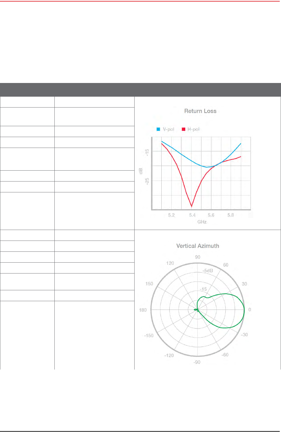
C.1.1 Bullet Line Station Antenna
The remote (line) station backhauls using the Ubiquiti Bullet radios support the following
antennas:
6 dBi antenna (65-0179) – This antenna is a UV stable, omnidirectional vented
radome that can sustain extreme weather conditions such as heat, wind, and rain,
and can be mounted to a mast, ceiling, or wall.
19 dBi directional antenna (65-0177) – This antenna is a UV-resistant, directional
flat-panel ABS plastic radome antenna with an aluminum back plate. It can be
surface or pole mounted and adjusted 45 degrees up or down.
Figure C–1 19 dBi Antenna
(65-0177)
Draft
148 RT System 2 v2.3.0 Deployment Guide R01.b
© 2010-2013 Wireless Seismic, Inc. All rights reserved.
C. Radio Specifications
Antenna Specifications
The supported line station antenna specifications are as follows:
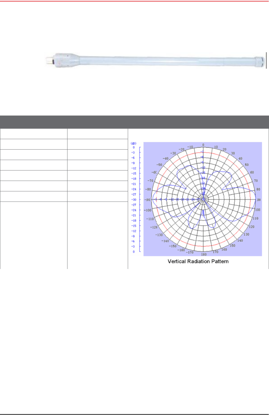
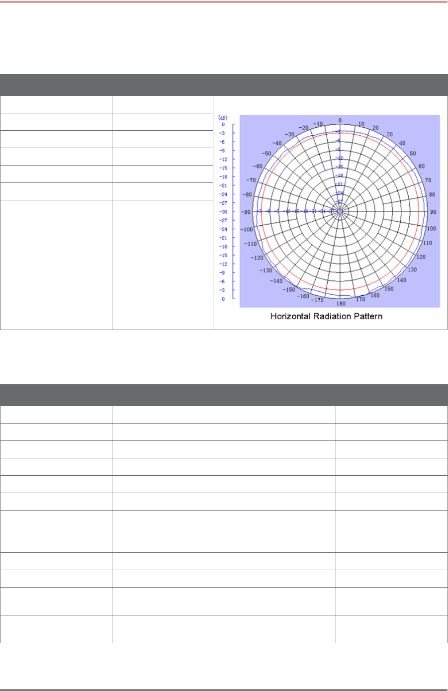
Figure C–2 6 dBi Antenna (65-0179)
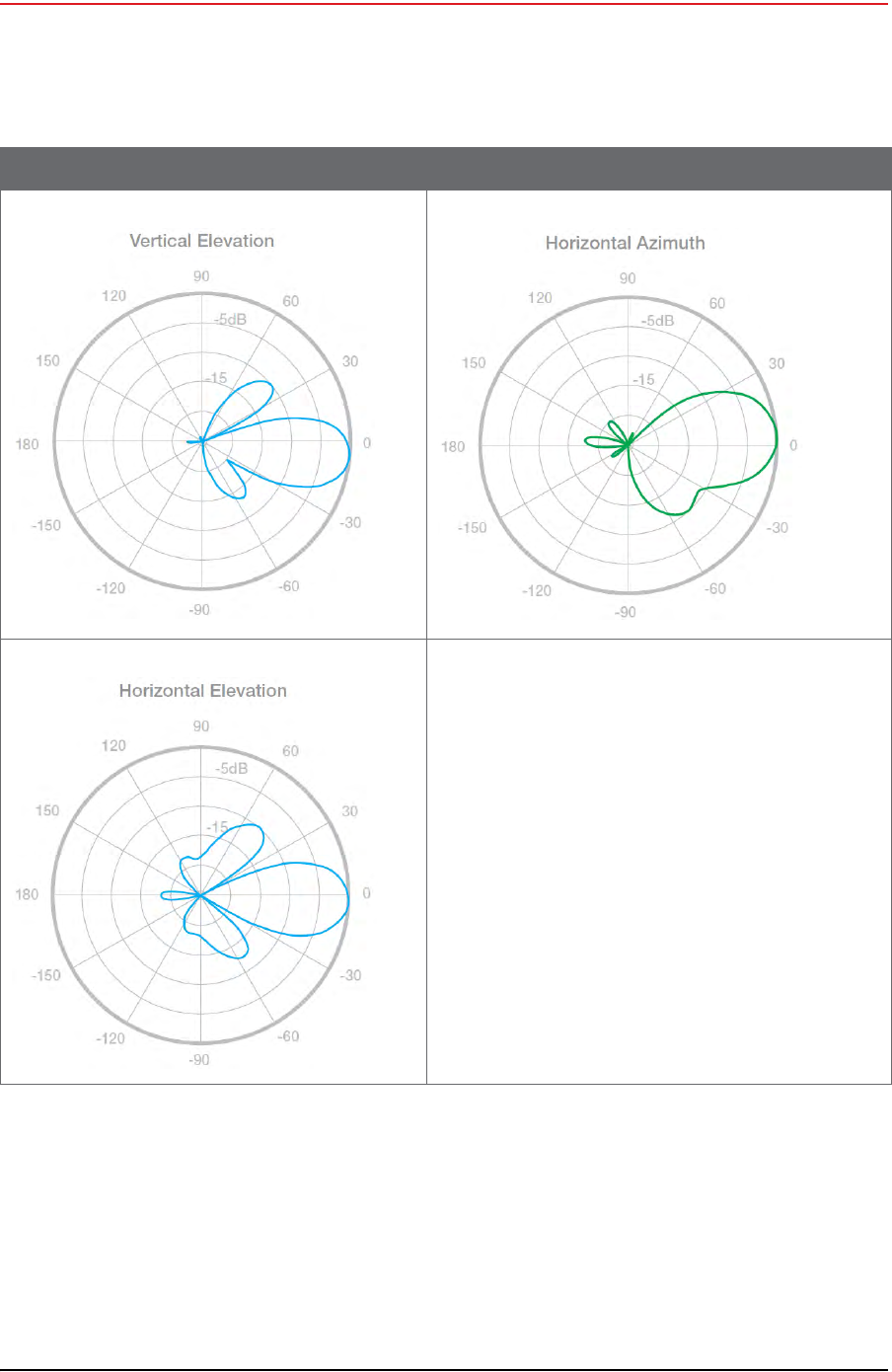
Table C–1 Antenna Specifications, 6 dBi (65-0179)
Item Description Radiation Patterns
Model T58060O10006
Frequency Range 5725 to 5850 MHz
Bandwidth 125 MHz
Gain 6 dBi
Vertical Beamwidth 25°
VSWR -/= 1.5
Impedance 50 Ohms
Polarization Vertical
Draft
R01.b RT System 2 v2.3.0 Deployment Guide 149
© 2010-2013 Wireless Seismic, Inc. All rights reserved.
C. Radio Specifications
Antenna Specifications
Maximum Power 100 Watts
Connector N-Style Jack
Height 10.6"
Weight 0.5 lbs
Horizontal Beamwidth 360°
Rated Wind Velocity 135 mph
Operating Temperature -22°F to 158 °F
-30 to 70 °C
Table C–1 Antenna Specifications, 6 dBi (65-0179) (cont.)
Item Description Radiation Patterns
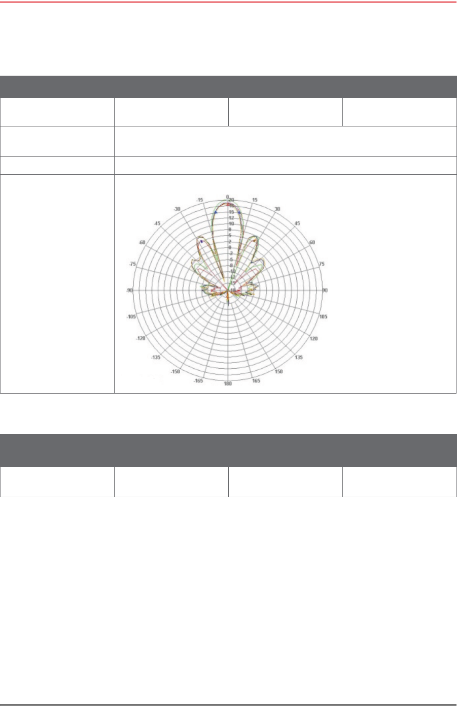
Table C–2 Antenna Specifications, 13 dBi (65-0177)
Parameter Min Typ Max
Frequency Range 5150 MHz 5825 MHz
Gain 19 dBi
Horizontal Beamwidth 16 Deg
Vertical Beamwidth 16 Deg
Front to Back 30 dB
Cross Polarization 25 dB
VSWR
• 5150-5350MHz
• 5470-5825MHz
2.0:1
1.5:1
Impedance 50 OHM
Input Power 100W
Operating Temperature -40 ºF
-40 °C 158 °F
70 °C
Pole Size 1 in
25 mm 2.5 in
64 mm
Draft
150 RT System 2 v2.3.0 Deployment Guide R01.b
© 2010-2013 Wireless Seismic, Inc. All rights reserved.
C. Radio Specifications
Antenna Specifications
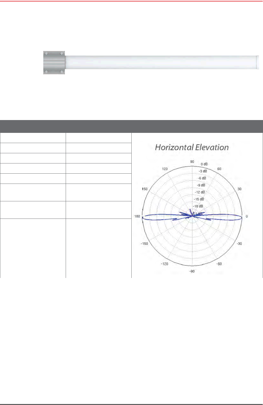
C.1.2 Rocket Recorder Antenna
The recorder station backhaul using the Ubiquiti Rocket radio supports a 13 dBi antenna. This
antenna is a 2x2 Dual Polarity MIMO Omnidirectional Antenna that provides 360 degree
coverage.
Weight 17.6 oz
0.5 kg
Dimension
(L x W x Thick) 7.5 x 7.5 x 0.8 in
190 x 190 x 20 mm
Bracket Tilt 45 Deg
Radiation Pattern
Table C–2 Antenna Specifications, 13 dBi (65-0177) (cont.)
Parameter Min Typ Max
Table C–3 Antenna Wind Loading, 13 dBi (65-0177)
Parameter Area 100 mph
161 kph 125 mph
201 kph
Wind Loading 56 sq in
0.04 sq m 14 lbs
6.4 kg 22 lbs
10 kg
Draft
R01.b RT System 2 v2.3.0 Deployment Guide 151
© 2010-2013 Wireless Seismic, Inc. All rights reserved.
C. Radio Specifications
Antenna Specifications
The supported recorder antenna specifications are as follows:
Figure C–3 13 dBi Antenna (65-0178)
Table C–4 Antenna Specifications, 13 dBi (65-0178)
Item Description Radiation Patterns
Frequency Range 5.45 to 5.85 GHz
Gain 13 dBi
Elevation Beamwidth 7 deg
Max VSWR 1.5:1
Downtilt 2 deg
Dimensions
L x W x H 6.2 x 3.8 x 32.8 in
158 x 98 x 834 mm
Weight
(including pole mount) 1 lb 13 oz
820 g
Wind Survivability 125 mph
201 kph
Draft
152 RT System 2 v2.3.0 Deployment Guide R01.b
© 2010-2013 Wireless Seismic, Inc. All rights reserved.
C. Radio Specifications
Antenna Specifications
Wind Loading 10 lb @ 100 mph
4.5 kg @ 161 kph
Polarization Dual Linear
Cross-pol Isolation 25 Db min
ETSI Specification EN 302 326 DN2
Mounting Universal pole mount
Table C–4 Antenna Specifications, 13 dBi (65-0178) (cont.)
Item Description Radiation Patterns
Draft
R01.b RT System 2 v2.3.0 Deployment Guide 153
© 2010-2013 Wireless Seismic, Inc. All rights reserved.
C. Radio Specifications
Antenna Specifications
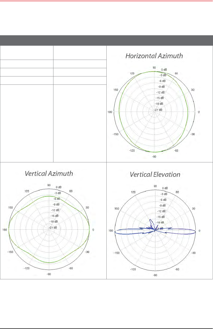
C.1.3 NanoStation Recorder/Line Station Antenna
The recorder or line station backhaul using the Ubiquiti NanoStation M5 radios do not use an
external antenna; the NanoStation M5 has an integrated 14 dBi dual-polarity antenna.
The NanoStation integrated antenna specifications are as follows:
Table C–5 NanoStation Integrated Antenna Specifications
Item Description Radiation Patterns
Model NSM5/+locoM5 integrated
Frequency Range 5745 to 5825 MHz (US)
5170 to 5875 MHz (INTL)
Cross Pol Isolation 20 dB Minimum
Gain 13 dBi
Beamwidth 45° (H-pol)
45° (V-pol)
45° (Elevation)
Max VSWR 1.4:1
Polarization Dual Linear
Maximum Power 5.5 Watts
Maximum Power 5.5 Watts
Connector N-Style Jack
Height 10.6"
Weight 0.5 lbs
Horizontal
Beamwidth 360°
Rated Wind Velocity 135 mph
Operating
Temperature -22°F to 158 °F
-30 to 70 °C
Draft
154 RT System 2 v2.3.0 Deployment Guide R01.b
© 2010-2013 Wireless Seismic, Inc. All rights reserved.
C. Radio Specifications
Radio Specifications
C.2 Radio Specifications
This section provides radio specifications. The following radios are used in the backhaul:
Bullet – 2.4 GHz High Power 802.11N Outdoor Radio System
See “Bullet Line Station Radios” on page 155
Table C–5 NanoStation Integrated Antenna Specifications (cont.)
Item Description Radiation Patterns

Draft
R01.b RT System 2 v2.3.0 Deployment Guide 155
© 2010-2013 Wireless Seismic, Inc. All rights reserved.
C. Radio Specifications
Radio Specifications
Rocket – 900 MHz High Power 2x2 MIMO AirMax TDMA BaseStation
See “Rocket Recorder Radios” on page 157
NanoStation M5 – 5.8 GHz, High power, 2x2 MIMO AirMax TDMA PoE station with
integrated 14 dBi dual-polarity antenna.
See “NanoStation Recorder/Line Station Radios” on page 158
C.2.1 Bullet Line Station Radios
The specifications for the Ubiquiti Bullet line station radio are as follows:
Table C–6 Bullet Line Station Radio Specifications (56-0019 US, 56-0024 Intl)
Item Description
System Information
Processor Specs Atheros MIPS 24KC, 400 MHz
Memory Information 32 MB SDRAM, 8 MB Flash
Networking Interface (1) 10/100 Ethernet Port
Regulatory / Compliance Information
Wireless Approvals FCC Part 15.247, IC RS210, CE
RoHS Compliance Yes
Physical / Electrical / Environmental
Dimensions
(length x width) 7.5 x 1.8 in
190 x 46 mm
Weight 6.9 oz
196 g
Enclosure Characteristics Powder Coated Aluminum
Antenna Connector N-Type Connector (male)
Power Supply 24V, 0.5A PoE Adapter (included)
Power Method Passive Power over Ethernet (pairs 4, 5+; 7, 8 return)
Max. Power Consumption 6 Watts
Operating Temperature -40 to 176 °F
-40 to 80 °C
Operating Humidity 5 to 95% Condensing
Shock and Vibration ETSI300-019-1.4
Software Information
Modes Station, Access Point, AP Repeater
Services SNMP, DHCP, NAT
Utilities Site Survey with Preferred SSID, Antenna Alignment
Tool, Discovery Utility

Draft
156 RT System 2 v2.3.0 Deployment Guide R01.b
© 2010-2013 Wireless Seismic, Inc. All rights reserved.
C. Radio Specifications
Radio Specifications
The power specifications for the Ubiquiti Bullet line station radio are as follows:
Security WEP/WPA/WPA2
QoS 802.11e / WMM Support
Statistical Reporting Ethernet Activity, Uptime, Packet Success/Errors
Operating Frequency 5725 to 5850 (USA)
5170 to 5825 (International)
Output Power 25 dBm
Range Performance 31+ mi
50+ km
(Outdoor - Antenna Dependent)
Table C–6 Bullet Line Station Radio Specifications (56-0019 US, 56-0024 Intl) (cont.)
Item Description
Table C–7 Bullet Line Station Radio Power Specifications (56-0019 US, 56-0024 Intl)
TX Power
Specifications
RX Power
Specifications
11a
Data
Rate
Avg.
TX T
olerance
11a
Data
Rate
Sensitivity
T
olerance
1-24
Mbps
25
dBm
+/-2
dB
24
Mbps
-83
dBm
+/-2
dB
36
Mbps
23
dBm
+/-2
dB
36
Mbps
-80
dBm
+/-2
dB
48
Mbps
21
dBm
+/-2
dB
48
Mbps
-77
dBm
+/-2
dB
54
Mbps
20
dBm
+/-2
dB
54
Mbps
-75
dBm
+/-2
dB
11n /
airMAX
MCS0 25
dBm
+/-2
dB
11n /
airMAX
MCS0 -96
dBm
+/-2
dB
MCS1 25
dBm
+/-2
dB
MCS1 -95
dBm
+/-2
dB
MCS2 25
dBm
+/-2
dB
MCS2 -92
dBm
+/-2
dB
MCS3 25
dBm
+/-2
dB
MCS3 -90
dBm
+/-2
dB
MCS4 24
dBm
+/-2
dB
MCS4 -86
dBm
+/-2
dB
MCS5 22
dBm
+/-2
dB
MCS5 -83
dBm
+/-2
dB
MCS6 20
dBm
+/-2
dB
MCS6 -77
dBm
+/-2
dB
MCS7 19
dBm
+/-2
dB
MCS7 -74
dBm
+/-2
dB

Draft
R01.b RT System 2 v2.3.0 Deployment Guide 157
© 2010-2013 Wireless Seismic, Inc. All rights reserved.
C. Radio Specifications
Radio Specifications
C.2.2 Rocket Recorder Radios
The specifications for the Ubiquiti Rocket recorder radio are as follows:
Table C–8 Rocket Recorder Radio Specifications (15-0052 US, 15-0054 Intl)
Item Description
System Information
Processor Specs Atheros MIPS 24KC, 400MHz
Memory Information 64MB SDRAM, 8MB Flash
Networking Interface 2 X 10/100 BASE-TX (Cat. 5, RJ-45) Ethernet
Regulatory / Compliance Information
Wireless Approvals FCC Part 15.247, IC RS210, CE
RoHS Compliance YES
Physical / Electrical / Environmental
Dimensions
(length, width, height) 6.7 x 3.1 x 1.2 in
17 x 8 x 3cm
Weight 1.6 lb
0.5kg
Enclosure Characteristics Outdoor UV Stabilized Plastic
RF Connector 2x RP-SMA and 1x SMA (Waterproof)
Mounting Kit Pole Mounting Kit included
Power Supply 24V, 1A POE Supply included
Power Method Passive Power over Ethernet (pairs 4, 5+; 7, 8 return)
Max Power Consumption 8 Watts
Operating Temperature -22 to 167 °F
-30 to 75 °C
Operating Humidity 5 to 95% Condensing
Shock and Vibration ETSI300-019-1.4
Operating Frequency 5745 to 5825 (USA)
5470 to 5825 (International)
Output Power 27 dBm
Range Performance up to 9.3 miles
up to 15 km

Draft
158 RT System 2 v2.3.0 Deployment Guide R01.b
© 2010-2013 Wireless Seismic, Inc. All rights reserved.
C. Radio Specifications
Radio Specifications
The power specifications for the Ubiquiti Rocket radio are as follows:
C.2.3 NanoStation Recorder/Line Station Radios
The specifications for the Ubiquiti NanoStation™ radio are as follows:
Table C–9 Rocket Recorder Radio Power Specifications (15-0052 US, 15-0054 Intl)
TX Power
Specifications
RX Power
Specifications
11a
Data
Rate
Avg.
TX T
olerance
11a
Data
Rate
Ave. TX
T
olerance
6-24 Mbps 27 dBm +/-2
dB
6-24 Mbps
-94 dBm
min +/-2
dB
36 Mbps 25 dBm +/-2
dB
36 Mbps -80 dBm +/-2
dB
48 Mbps 23 dBm +/-2
dB
48 Mbps -77 dBm +/-2
dB
54 Mbps 22 dBm +/-2
dB
54 Mbps -75 dBm +/-2
dB
11n /
airMAX
MCS0 27 dBm +/-
2 dB
11n /
airMAX
MCS0 -96 dBm +/-
2 dB
MCS1 27 dBm +/-
2 dB
MCS1 -95 dBm +/-
2 dB
MCS2 27 dBm +/-
2 dB
MCS2 -92 dBm +/-
2 dB
MCS3 27 dBm +/-
2 dB
MCS3 -90 dBm +/-
2 dB
MCS4 26 dBm +/-
2 dB
MCS4 -86 dBm +/-
2 dB
MCS5 24 dBm +/-
2 dB
MCS5 -83 dBm +/-
2 dB
MCS6 22 dBm +/-
2 dB
MCS6 -77 dBm +/-
2 dB
MCS7 21 dBm +/-
2 dB
MCS7 -74 dBm +/-
2 dB
MCS8 27 dBm +/-
2 dB
MCS8 -95 dBm +/-
2 dB
MCS9 27 dBm +/-
2 dB
MCS9 -93 dBm +/-
2 dB
MCS10 27 dBm +/-
2 dB
MCS10 -90 dBm +/-
2 dB
MCS11 27 dBm +/-
2 dB
MCS11 -87 dBm +/-
2 dB
MCS12 26 dBm +/-
2 dB
MCS12 -84 dBm +/-
2 dB
MCS13 24 dBm +/-
2 dB
MCS13 -79 dBm +/-
2 dB
MCS14 22 dBm +/-
2 dB
MCS14 -78 dBm +/-
2 dB
MCS15 21 dBm +/-
2 dB
MCS15 -75 dBm +/-
2 dB
Table C–10 NanoStation Radio Specifications (56-0035 US, 56-0032 Intl)
Item Description
System Information
Processor Specs Atheros MIPS 24KC, 400MHz
Memory Information 32MB SDRAM, 8MB Flash
Networking Interface 1 X 10/100 BASE-TX (Cat. 5, RJ-45) Ethernet
Regulatory / Compliance Information

Draft
R01.b RT System 2 v2.3.0 Deployment Guide 159
© 2010-2013 Wireless Seismic, Inc. All rights reserved.
C. Radio Specifications
Radio Specifications
The power specifications for the Ubiquiti NanoStation M5 radio are as follows:
Wireless Approvals FCC Part 15.247, IC RS210, CE
RoHS Compliance YES
Physical / Electrical / Environmental
Dimensions
(length, width, height) 6.42 x 1.22 x 3.15 in
163 x 31 x 80mm
Weight 0.40 lb
0.18kg
Enclosure Characteristics Outdoor UV Stabilized Plastic
Mounting Kit Pole Mounting Kit included
Power Supply 24V, 0.5A POE Supply included
Power Method Passive Power over Ethernet
(pairs 4, 5+; 7, 8 return)
Max Power Consumption 5.5 Watts
Operating Temperature -22 to 167 °F
-30 to 75 °C
Operating Humidity 5 to 95% Condensing
Shock and Vibration ETSI300-019-1.4
Operating Frequency 5745 to 5825 (USA)
5170 to 5875 (International)
Output Power 27 dBm
Range Performance 31+ mile
50+ km
Table C–10 NanoStation Radio Specifications (56-0035 US, 56-0032 Intl) (cont.)
Item Description
Table C–11 NanoStation Radio Power Specifications (56-0035 US, 56-0032 Intl)
TX Power
Specifications
RX Power
Specifications
11a
Data
Rate
Avg.
TX T
olerance
11a
Data
Rate
Ave. TX
T
olerance
6-24Mbps 23 dBm +/-2
dB
6-24Mbps
-83 dBm
min +/-2
dB
36 Mbps 21 dBm +/-2
dB
36 Mbps -80 dBm +/-2
dB
48 Mbps 19 dBm +/-2
dB
48 Mbps -77 dBm +/-2
dB
54 Mbps 18 dBm +/-2
dB
54 Mbps -75 dBm +/-2
dB

Draft
160 RT System 2 v2.3.0 Deployment Guide R01.b
© 2010-2013 Wireless Seismic, Inc. All rights reserved.
C. Radio Specifications
Radio Specifications
11n /
airMAX
MCS0 23 dBm +/-
2 dB
11n /
airMAX
MCS0 -96 dBm +/-
2 dB
MCS1 23 dBm +/-
2 dB
MCS1 -95 dBm +/-
2 dB
MCS2 23 dBm +/-
2 dB
MCS2 -92 dBm +/-
2 dB
MCS3 23 dBm +/-
2 dB
MCS3 -90 dBm +/-
2 dB
MCS4 22 dBm +/-
2 dB
MCS4 -86 dBm +/-
2 dB
MCS5 20 dBm +/-
2 dB
MCS5 -83 dBm +/-
2 dB
MCS6 18 dBm +/-
2 dB
MCS6 -77 dBm +/-
2 dB
MCS7 17 dBm +/-
2 dB
MCS7 -74 dBm +/-
2 dB
MCS8 23 dBm +/-
2 dB
MCS8 -95 dBm +/-
2 dB
MCS9 23 dBm +/-
2 dB
MCS9 -93 dBm +/-
2 dB
MCS10 23 dBm +/-
2 dB
MCS10 -90 dBm +/-
2 dB
MCS11 23 dBm +/-
2 dB
MCS11 -87 dBm +/-
2 dB
MCS12 22 dBm +/-
2 dB
MCS12 -84 dBm +/-
2 dB
MCS13 20 dBm +/-
2 dB
MCS13 -79 dBm +/-
2 dB
MCS14 18 dBm +/-
2 dB
MCS14 -78 dBm +/-
2 dB
MCS15 17 dBm +/-
2 dB
MCS15 -75 dBm +/-
2 dB
Table C–11 NanoStation Radio Power Specifications (56-0035 US, 56-0032 Intl) (cont.)
TX Power
Specifications
RX Power
Specifications

Draft
RT System 2 v2.3.0 161 Deployment Guide R01.b
© 2010-2013 Wireless Seismic, Inc. All rights reserved.
D
D. LED Indicators
This chapter provides the possible LED status and error indicators for WRUs and LIUs.
The WRU has three possible states; undeployed, deploying, and deployed.
When tilting the WRU to deploy, re-acquire GPS, or check status, tilt the WRU geophone
down until the LEDs light, and then return the WRU to the horizontal position as shown
in the following figure:
When tilting the WRU to undeploy, tilt the WRU geophone up until the LEDs light, and
then return the WRU to the horizontal position as shown in the following figure:
D.1 WRU Undeployed
When the WRU is undeployed, all of the LEDs are off. A vertical tilt has the following
effect:
Geophone Down – WRU deployment
Geophone Up – No effect; nothing happens
Figure D–1 WRU Down-Tilt Action
Figure D–2 WRU Up-Tilt Action

Draft
162 RT System 2 v2.3.0 Deployment Guide R01.b
© 2010-2013 Wireless Seismic, Inc. All rights reserved.
D. LED Indicators
WRU Undeployed
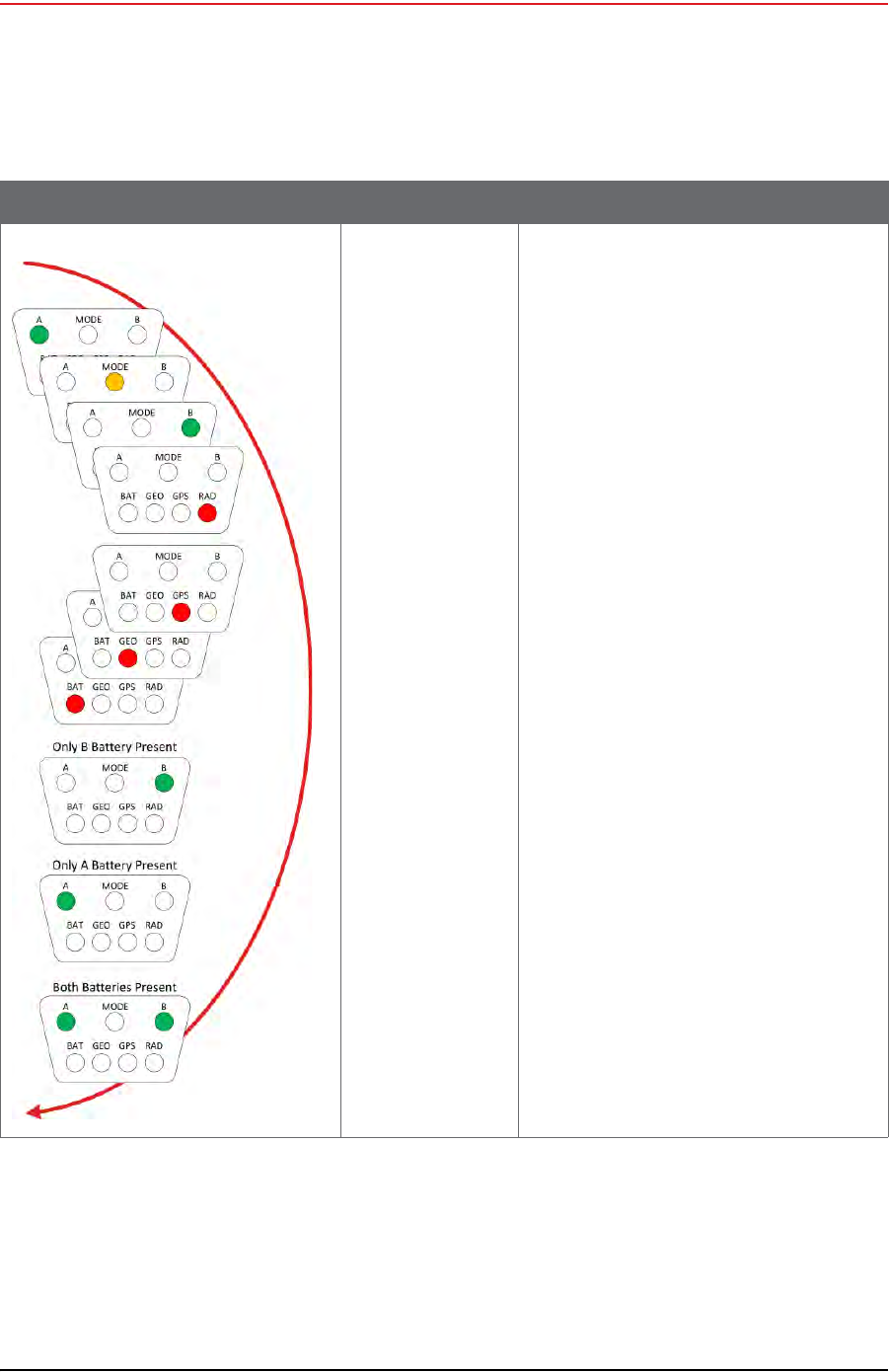
After removing both batteries from an undeployed WRU, and then replacing BAT A, BAT B, or
both, when the first battery is connected, the WRU goes through the power on LED sequence
and then remains in the undeployed state.
The following table shows the LED power-on sequence for an undeployed WRU:
Table D–1 WRU LED Indications, Undeployed
LED Indicators Summary Description
Undeployed
Dead batteries If no LEDs are on (lit up) on an undeployed
WRU, it can be one of the following scenarios:
• Unit undeployed
• Batteries dead
When you do a tilt test (geophone down) on
an undeployed WRU with no LEDs on, the
following may occur:
• An Undeployed WRU deploys and begins
the self tests
• A WRU with dead batteries will continue
to display no lit LEDs
• A WRU is defective if no LEDs turn on
after battery replacement.
NOTE: Battery state is shown in the RT
System 2 user interface tables. For
example, the Ground Equipment
Table.
Geo down tilt
detected
Deploy
Tilt the WRU with the geophone pointing
down.
After a few seconds, all of the LEDs light up
solid.
Place the WRU flat on the ground to within
five seconds to begin the deployment
process:
• Battery fuse self-test
• Battery test
•THD test
• Geophone test
• GPS fix
•Radio test
Draft
R01.b RT System 2 v2.3.0 Deployment Guide 163
© 2010-2013 Wireless Seismic, Inc. All rights reserved.
D. LED Indicators
WRU Deploying
D.2 WRU Deploying
When the WRU begins deploying, the following tests are executed:
Table D–2 WRU LED Indications, Undeployed Power-On Sequence
LED Indicators Summary Description
Hard reset
(power on) The LEDs light up in clockwise rotation
starting with the A battery LED and ending
with the A battery LED, B battery LED, or
both.

Draft
164 RT System 2 v2.3.0 Deployment Guide R01.b
© 2010-2013 Wireless Seismic, Inc. All rights reserved.
D. LED Indicators
WRU Deploying
BAT A and BAT B connected
●Battery fuse test
●Battery test
●THD test
●Geophone Test
●GPS test
●Radio Test
BAT A or BAT B connected
●Battery test
●THD test
●Geophone Test
●GPS test
●Radio Test
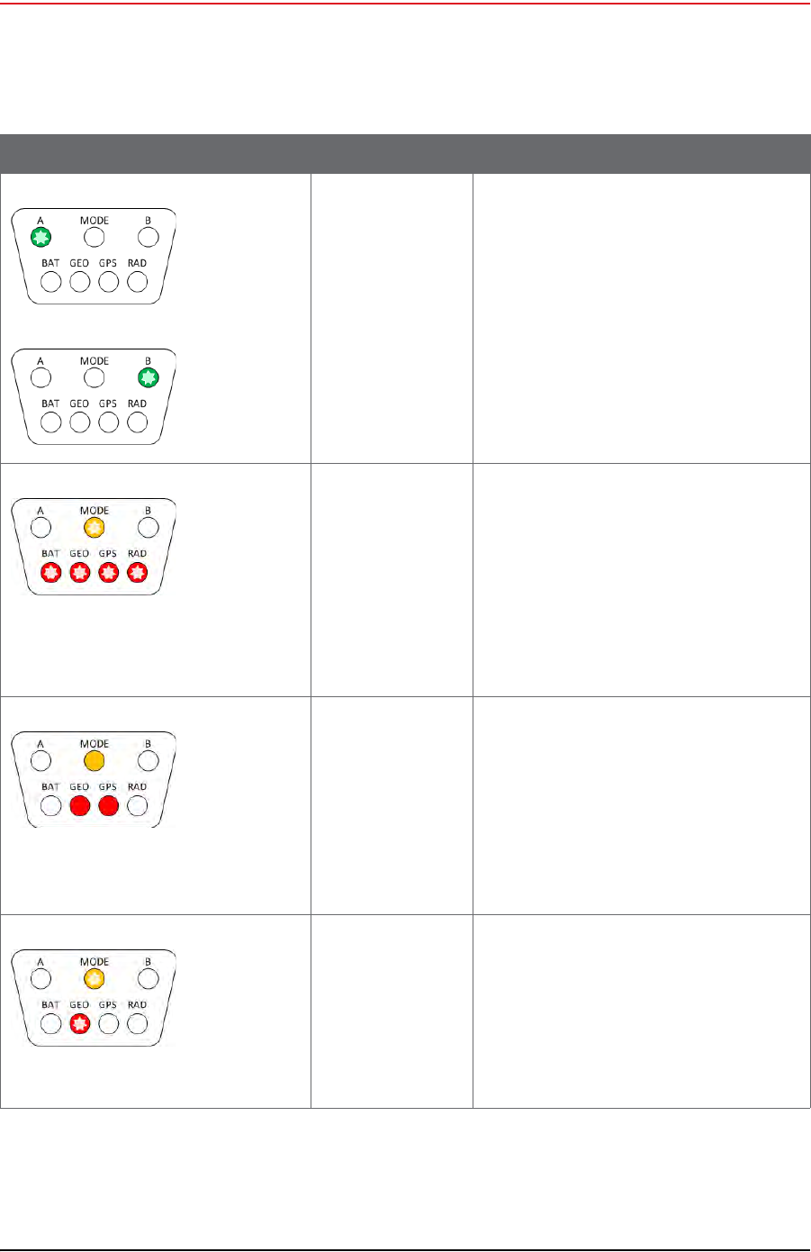
The following table shows the possible LED indicators for a WRU that is deploying:
Table D–3 WRU LED Indications, Deploying Sequence
LED Indicators Summary Description
Dead batteries
Defective Unit If no LEDs are on (lit up) during the deploying
state, it can be one of the following scenarios:
• Batteries dead
•Defective Unit
When you do a tilt test (geophone down) on a
WRU with no LEDs on, the following may
occur:
• A WRU with dead batteries will continue
to display no lit LEDs
• A WRU is defective if no LEDs turn on
after battery replacement.
NOTE: Battery state is shown in the RT
System 2 user interface tables. For
example, the Ground Equipment
Table.
A is solid for 5 seconds
BAT remains solid
Battery fuse test
failure (A) When both batteries are installed, the battery
fuse test is performed.
A Solid for 5 seconds
BAT Solid
A solid BAT LED indicates that the WRU
detected a bad fuse during deployment and
returned to the undeployed state. When a
battery fuse test fails, the WRU will not
deploy.
Both batteries must be present for the battery
fuse test to execute. This allows you to deploy
a WRU by removing the battery connected to
the bad fuse prior to the deployment tilt
action.

Draft
R01.b RT System 2 v2.3.0 Deployment Guide 165
© 2010-2013 Wireless Seismic, Inc. All rights reserved.
D. LED Indicators
WRU Deploying
B is solid for 5 seconds
BAT remains solid
Battery fuse test
failure (B) When both batteries are installed, the battery
fuse test is performed.
B Solid for 5 seconds
BAT Solid
A solid BAT LED indicates that the WRU
detected a bad fuse during deployment and
returned to the undeployed state. When a
battery fuse test fails, the WRU will not
deploy.
Both batteries must be present for the battery
fuse test to execute. This allows you to deploy
a WRU by removing the battery connected to
the bad fuse prior to the deployment tilt
action.
Battery test If both batteries are installed and their
capacities are above 9000 mAh, the following
occurs:
• Battery in use LED (A or B) Flashes
• The THD, GEO, GPS, and RAD self-tests
are performed
NOTE: The general battery test provides a
visual indication if the WRU has one
or more missing, malfunctioning, or
low capacity batteries and provides
45 seconds to correct the problem
before proceeding to the remainder
of the deployment self-tests.
Battery failure If one or both batteries have sub-9000mAh
capacities or are not installed, the following
occurs:
•Solid – A and or B
• Flashing – BAT LED flashes for 45
seconds
Install one or two batteries with capacities
above 9000 mAh during the 45 second
window. The following occurs:
• Flashing BAT LED turns off
• Battery in use LED (A or B) flashes for
approximately 2 seconds
• The THD, GEO, GPS, and RAD self-tests
are performed
Table D–3 WRU LED Indications, Deploying Sequence (cont.)
LED Indicators Summary Description
Draft
166 RT System 2 v2.3.0 Deployment Guide R01.b
© 2010-2013 Wireless Seismic, Inc. All rights reserved.
D. LED Indicators
WRU Deploying
If no changes are made to the batteries
within the 45 second window, The following
occurs:
• Flashing BAT LED turns off
• Battery in use LED (A or B) flashes for
approximately 2 seconds
• The THD, GEO, GPS, and RAD self-tests
are executed
Self-test starting If a WRU self-test fails, the WRU will continue
to the next test.
Flashing:
•MODE
•BAT
•GEO
•GPS
•RAD
NOTE: Error LEDs remain persistent
throughout the self-discovery process
and are turned off upon completion.
Continue (lay flat to
move to next test) To skip a test during the self-test process, tilt
the WRU geophone down until you see this
triangle of LEDs. Tilt the WRU back to
horizontal to continue.
Solid:
•MODE
•GEO
•GPS
NOTE: The GPS test cannot be skipped.
Geophone test in
progress Flashing:
•MODE
•GEO
NOTE: Performing a vertical geophone down
tilt during the geophone test causes
the WRU to go into the
communications repeater mode.
WRU repeaters are used to solve
terrain or distance related
communication problems between
WRUs.
Table D–3 WRU LED Indications, Deploying Sequence (cont.)
LED Indicators Summary Description
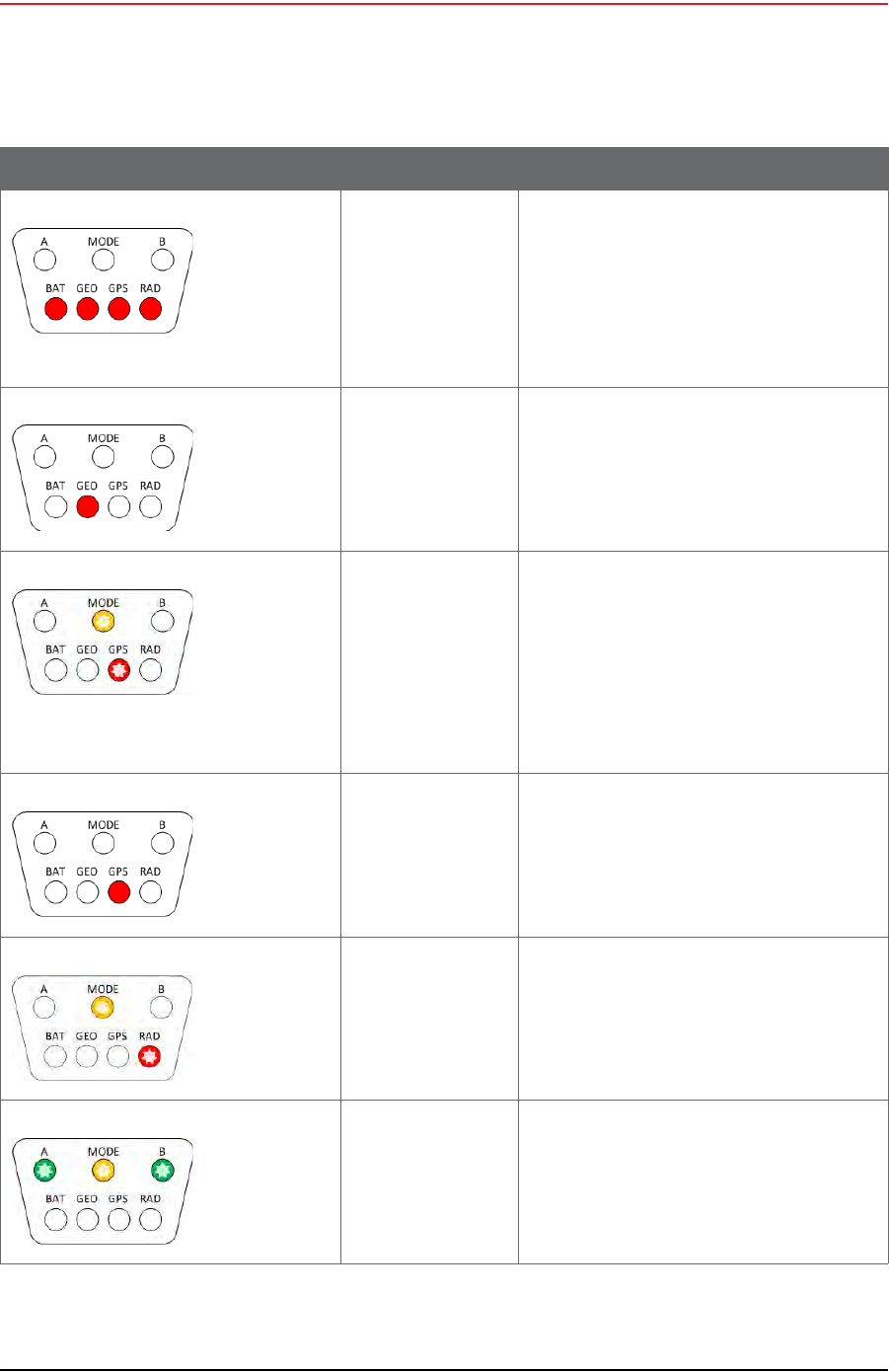
Draft
R01.b RT System 2 v2.3.0 Deployment Guide 167
© 2010-2013 Wireless Seismic, Inc. All rights reserved.
D. LED Indicators
WRU Deploying
THD test failure Solid:
•BAT
•GEO
•GPS
•RAD
NOTE: No LEDs are affected when the THD
test starts or when it passes.
Geophone test
failure GEO Solid
NOTE: For a multiple-channel geophone,
tests the first channel only.
Acquiring GPS fix Flashing:
•MODE
•GPS
NOTE: The WRU will attempt to get a 3-
meter GPS lock for up to 15 minutes.
During this time, the GPS LED
flashes. The WRU will not form until
the GPS lock is achieved. If the GPS
lock cannot be achieved, form by
serial number.
GPS test failure GPS Solid
GPS fix not found
For a multiple-channel geophone, tests the
first channel only.
Neighbor discovery
in progress Flashing:
•MODE
•RAD
Neighbor discovered Flashing:
•A
•MODE
•B
Table D–3 WRU LED Indications, Deploying Sequence (cont.)
LED Indicators Summary Description

Draft
168 RT System 2 v2.3.0 Deployment Guide R01.b
© 2010-2013 Wireless Seismic, Inc. All rights reserved.
D. LED Indicators
WRU Deploying
If power is removed from a WRU in the deploying state, the WRU stays in the deploying state
and restarts the deploying process when power is restored.
After removing both batteries from a deploying WRU, and then replacing BAT A, BAT B, or
both, when the first battery is connected, the WRU goes through the power on LED
sequence. If both batteries are connected, the battery fuse test is executed. If only one
battery is connected, the battery fuse test is skipped. The remainder of the self-tests are
then executed.
The following table shows the LED power-on sequence for an deploying WRU:
No neighbor
detected RAD Solid
If this is the first WRU deployed, this is the
expected condition.
Table D–3 WRU LED Indications, Deploying Sequence (cont.)
LED Indicators Summary Description
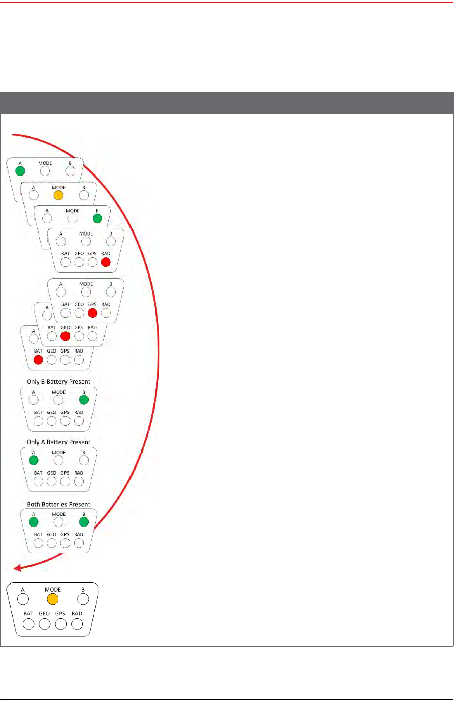
Draft
R01.b RT System 2 v2.3.0 Deployment Guide 169
© 2010-2013 Wireless Seismic, Inc. All rights reserved.
D. LED Indicators
WRU Deploying
Table D–4 WRU LED Indications, Deploying Power-On Sequence
LED Indicators Summary Description
Hard reset
(power on) The LEDs light up in clockwise rotation
starting with the A battery LED and ending
with the A battery LED, B battery LED, or
both for 2 seconds.
The A and B battery LEDs at the end of the
rotation indicate that one or both batteries
are above the minimum threshold of
9000mAh.
Finally, the MODE LED lights up for
approximately 5 seconds indicating that the
WRU is verifying its firmware integrity.

Draft
170 RT System 2 v2.3.0 Deployment Guide R01.b
© 2010-2013 Wireless Seismic, Inc. All rights reserved.
D. LED Indicators
WRU Deployed
D.3 WRU Deployed
If the WRU is already deployed, a vertical tilt has the following effect:
Geophone Down – If Sleeping, takes three to four seconds to wake up. If in Standby or
Armed displays the battery status, deployment self-test status, and re-acquires the GPS
position.
Geophone Up – All lights light. If placed flat within 5 seconds, the WRU undeploys.
The following table shows how the LEDs light up during normal operation with no vertical tilt
for a deployed WRU.
The following table shows how the LEDs light up during a vertical tilt (geophone down) for a
deployed WRU.
Table D–5 WRU LED Indications, Deployed WRU, No Geophone Tilt
LED Indicators Summary Description
Undeployed
Dead Batteries
Sleeping
If no LEDs are on (lit up), it can be one of the
following scenarios:
• WRU undeployed
• Batteries dead
•WRU Sleeping
• WRU Awake, but unformed
NOTE: Battery state is shown in the RT
System 2 user interface tables. For
example, the Ground Equipment
Table.
Battery A in use A Flashing:
• Battery A in use
• WRU formed or Armed
Battery B in use B Flashing:
• Battery B in use
• WRU formed or Armed

Draft
R01.b RT System 2 v2.3.0 Deployment Guide 171
© 2010-2013 Wireless Seismic, Inc. All rights reserved.
D. LED Indicators
WRU Deployed
Table D–6 WRU LED Indications, Deployed WRU, Geophone Down Tilt
LED Indicators Summary Description
Undeployed
Dead Batteries
Sleeping
If no LEDs are on (lit up) before tilting the
WRU, it can be one of the following scenarios:
• WRU undeployed
• Batteries dead
•WRU Sleeping
• WRU Awake, but unformed
When you do a tilt test (geophone down) on a
WRU with no LEDs on, the following may
occur:
• An Undeployed WRU deploys and begins
the self tests
• A WRU with dead batteries will continue
to display no lit LEDs
• A Sleeping WRU goes back to the
deployed, unformed state and displays
the battery status and any self-tests that
failed during deployment (BAT, THD, GEO,
GPS, or RAD).
• A WRU in the Awake unformed state
displays the battery status and any self-
tests that failed during deployment (BAT,
THD, GEO,GPS, or RAD).
NOTE: Battery state is shown in the
RT System 2 user interface tables.
For example, the Ground Equipment
Table.
Battery A in use A Flashing:
• Battery A in use
• WRU formed or Armed
NOTE: Only when GPS position occurs at the
same time the battery status is
displayed.
Battery B in use B Flashing:
• Battery B in use
• WRU formed or Armed
NOTE: Only when no self-test failures. Re-
acquire GPS position occurs at the
same time the battery status is
displayed.
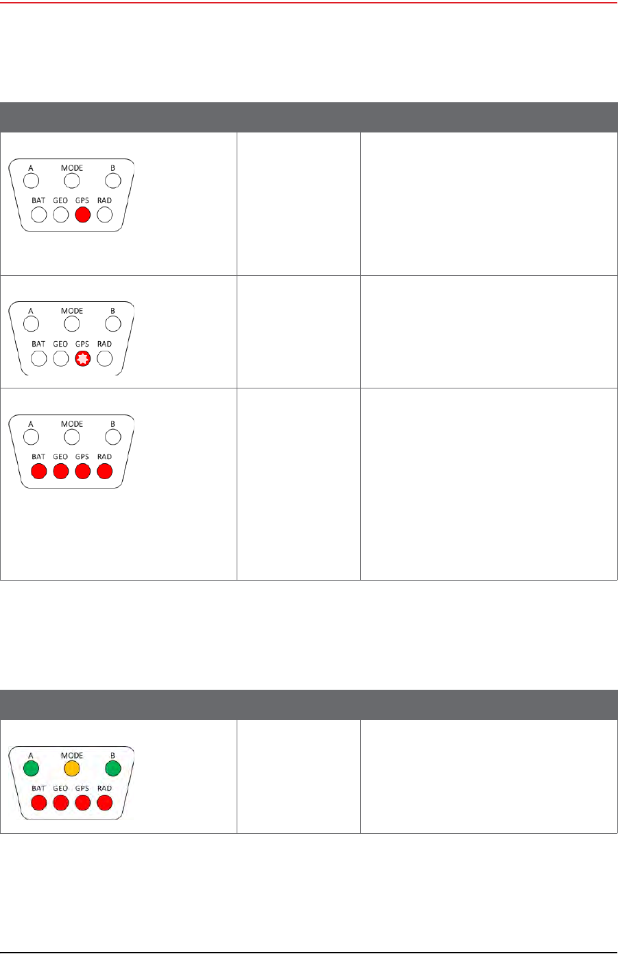
Draft
172 RT System 2 v2.3.0 Deployment Guide R01.b
© 2010-2013 Wireless Seismic, Inc. All rights reserved.
D. LED Indicators
WRU Deployed
The following table shows how the LEDs light up during a vertical tilt (geophone up) for a
deployed WRU.
Re-acquire GPS
position GPS Solid for up to 15 minutes
The deployed WRU can be in any of the
following states:
•Unformed
•Formed
NOTE: The battery status is displayed at the
same time the GPS position is re-
acquiring.
GPS position
acquired GPS Flashing
The Deployed WRU is in Standby
Self test failure The LED associated with the failed self-test is
solid. All four LEDs are solid only if all four
self-tests failed, or the THD self-test fails.
The LEDs are visible only during the
deployment process, and when the WRU is
tilted (geophone down) to check status after
the WRU is deployed.
Solid:
•BAT
•GEO
•GPS
•RAD
Table D–6 WRU LED Indications, Deployed WRU, Geophone Down Tilt (cont.)
LED Indicators Summary Description
Table D–7 WRU LED Indications, Deployed WRU, Geophone Up Tilt
LED Indicators Summary Description
Geo tilt detected
Undeploy Tilt the WRU with the geophone pointing up.
After a few seconds, all of the LEDs light up
solid.
Place the WRU flat on the ground within five
seconds to undeploy the WRU.
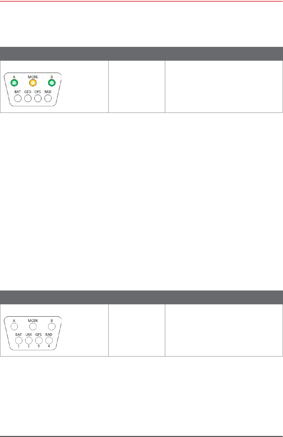
Draft
R01.b RT System 2 v2.3.0 Deployment Guide 173
© 2010-2013 Wireless Seismic, Inc. All rights reserved.
D. LED Indicators
LIU Power-On
After removing both batteries from a deployed WRU, and then replacing BAT A, BAT B, or
both, when the first battery is connected, the WRU goes through the power on LED
sequence. The WRU transitions to the Awake, unformed state. If the WRU is not formed
within 30 minutes, the WRU transitions to the Sleep state.
D.4 LIU Power-On
The LIU LEDs function independently from each other, and there can be a number of
combinations of LEDs that are on, off, or flashing. The following list shows the LEDs used to
indicate status:
Battery – A, B, BAT
Power, Mode – MODE
Discipline – MODE
Check Link Status – MODE, 1, 2, 3, and 4
Connection to Central – LNK
GPS Lock – GPS
Radio connection, communication with neighbor – RAD
The following table shows the LED power-on sequence for an LIU:
Undeploy successful Flashing:
•A
•MODE
•B
Table D–7 WRU LED Indications, Deployed WRU, Geophone Up Tilt (cont.)
LED Indicators Summary Description
Table D–8 LIU LED Indications, Power-On Sequence
LED Indicators Summary Description
Off No lights
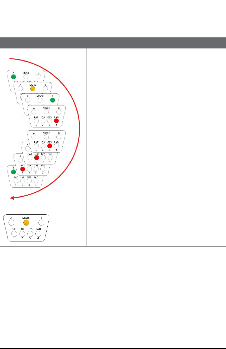
Draft
174 RT System 2 v2.3.0 Deployment Guide R01.b
© 2010-2013 Wireless Seismic, Inc. All rights reserved.
D. LED Indicators
LIU Normal Operation
D.5 LIU Normal Operation
The following tables describe the possible Normal Mode LIU Status Indications:
“LIU LED Status Indications, Normal Mode” on page 175
“LIU LED Error Indications, Normal Mode” on page 177
Hard Reset LIU The LEDs light up in clockwise rotation
starting and ending with the A battery LED in
the following cases:
• When the batteries are attached
• Anytime the unit resets itself
• In between updating firmware
applications
The unit is verifying
the integrity of the
firmware.
MODE Solid for approximately 5 seconds
Table D–8 LIU LED Indications, Power-On Sequence (cont.)
LED Indicators Summary Description
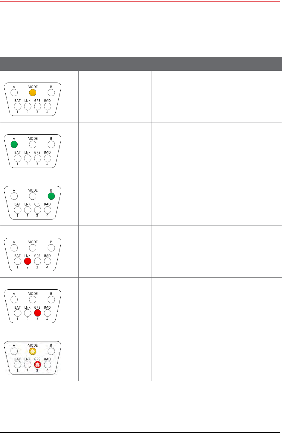
Draft
R01.b RT System 2 v2.3.0 Deployment Guide 175
© 2010-2013 Wireless Seismic, Inc. All rights reserved.
D. LED Indicators
LIU Normal Operation
Table D–9 LIU LED Status Indications, Normal Mode
LED Indicators Summary Description
On, Disciplined to GPS
Checking firmware
MODE solid
The MODE LED indicates that the integrity of the
downloaded firmware is being verified.
Battery A in use A solid
Indicates Battery A in use powering LIU. Battery
Voltage is above depleted threshold.
Battery B in use B solid
Indicates Battery B in use powering LIU. Battery
Voltage is above depleted threshold.
LIU connected to Central LNK solid
GPS lock GPS solid
GPS disciplined Flashing:
• GPS flashes in the 1 s rhythm of the PPS
• MODE flashes in the 1 s rhythm of the PPS
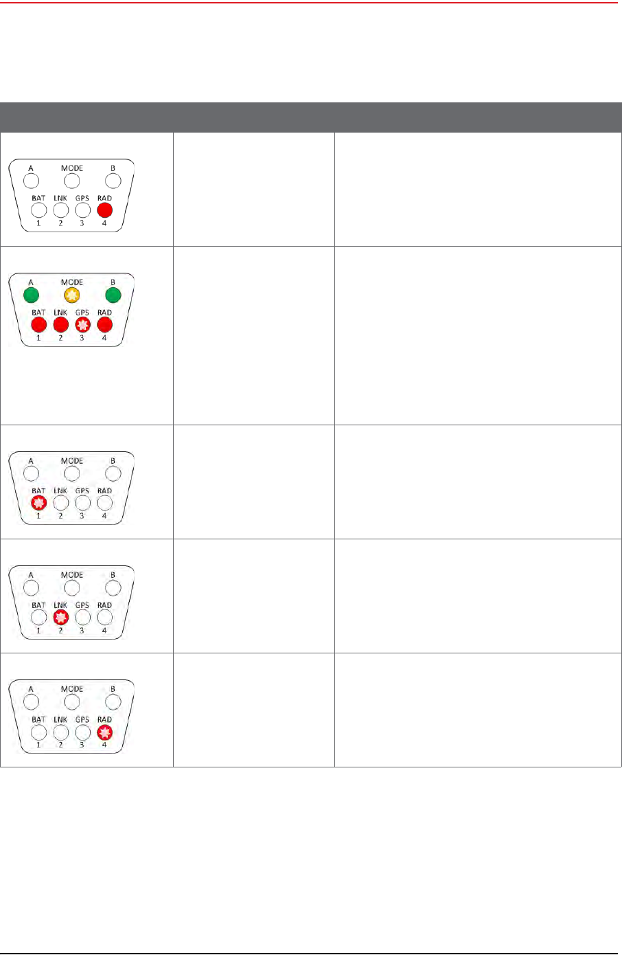
Draft
176 RT System 2 v2.3.0 Deployment Guide R01.b
© 2010-2013 Wireless Seismic, Inc. All rights reserved.
D. LED Indicators
LIU Normal Operation
Formed RAD solid
Normal Solid:
•A/B
•BAT
• LNK (connected)
•RAD (formed)
Flashing:
•MODE
•GPS
• LNK (disconnected)
Main (ARM) processor is
upgrading its own firmware BAT flashing
Main (ARM) processor is
upgrading the Power
Control (XMEGA) processor
firmware
LNK flashing
Main (ARM) processor is
upgrading the Radio
processor firmware
RAD flashing
Table D–9 LIU LED Status Indications, Normal Mode (cont.)
LED Indicators Summary Description
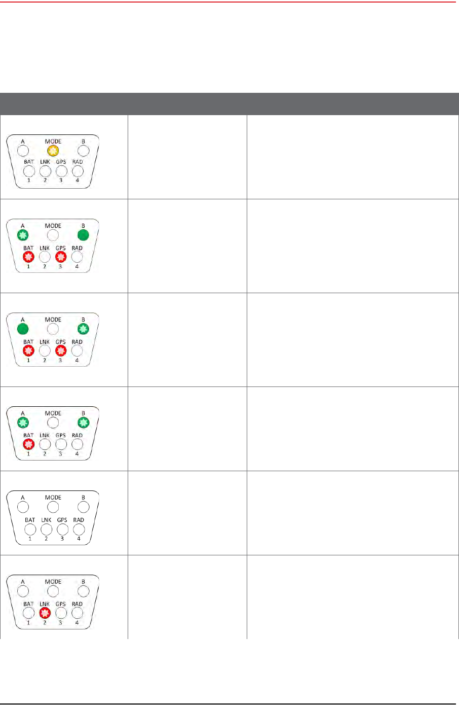
Draft
R01.b RT System 2 v2.3.0 Deployment Guide 177
© 2010-2013 Wireless Seismic, Inc. All rights reserved.
D. LED Indicators
LIU Normal Operation
Table D–10 LIU LED Error Indications, Normal Mode
LED Indicators Summary Description
On, no GPS discipline MODE flashing every 1 second
Single battery failure
Battery B in use
Battery A below threshold
or disconnected
A:
•Off, or
• 4 long flashes, then off (On 4.5s, off 2s) or
• GPS PPS flash
B Solid
BAT:
• 4 long flashes, then off (On 4.5s, off 2s)
Single battery failure
Battery A in use
Battery B below threshold
or disconnected
A Solid
B:
•Off, or
• 4 long flashes, then off (On 4.5s, off 2s) or
• GPS PPS flash
BAT:
• 4 long flashes, then off (On 4.5s, off 2s)
Both batteries below
threshold
–OR–
One below threshold and
one disconnected
A & B:
•Off, or
• 4 long flashes, then off (On 4.5s, off 2s) or
• GPS PPS flashes
BAT:
• 4 long flashes, then off (On 4.5s, off 2s)
No IP Address acquired LNK off
LIU has IP Address, but no
communications with
Central
LNK flashing
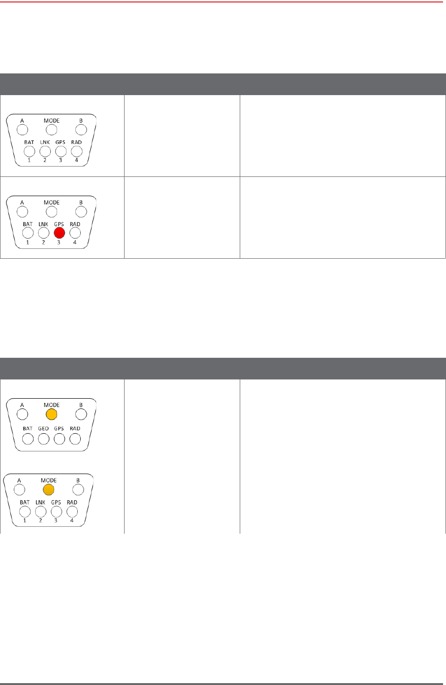
Draft
178 RT System 2 v2.3.0 Deployment Guide R01.b
© 2010-2013 Wireless Seismic, Inc. All rights reserved.
D. LED Indicators
Firmware Upgrade
D.6 Firmware Upgrade
The following table describes the possible WRU and LIU LED indications during firmware
upgrade:
No GPS lock GPS off
No GPS or less than 3 satellites
GPS lock, not disciplined GPS on
GPS lock, but not disciplined
Table D–10 LIU LED Error Indications, Normal Mode (cont.)
LED Indicators Summary Description
Table D–11 WRU and LIU LED Status Indications, Firmware Upgrade
LED Indicators Summary Description
Firmware upgrade MODE Solid for approximately 5 seconds
During firmware upgrade, the MODE LED indicates
that each processor's new firmware is being
verified.
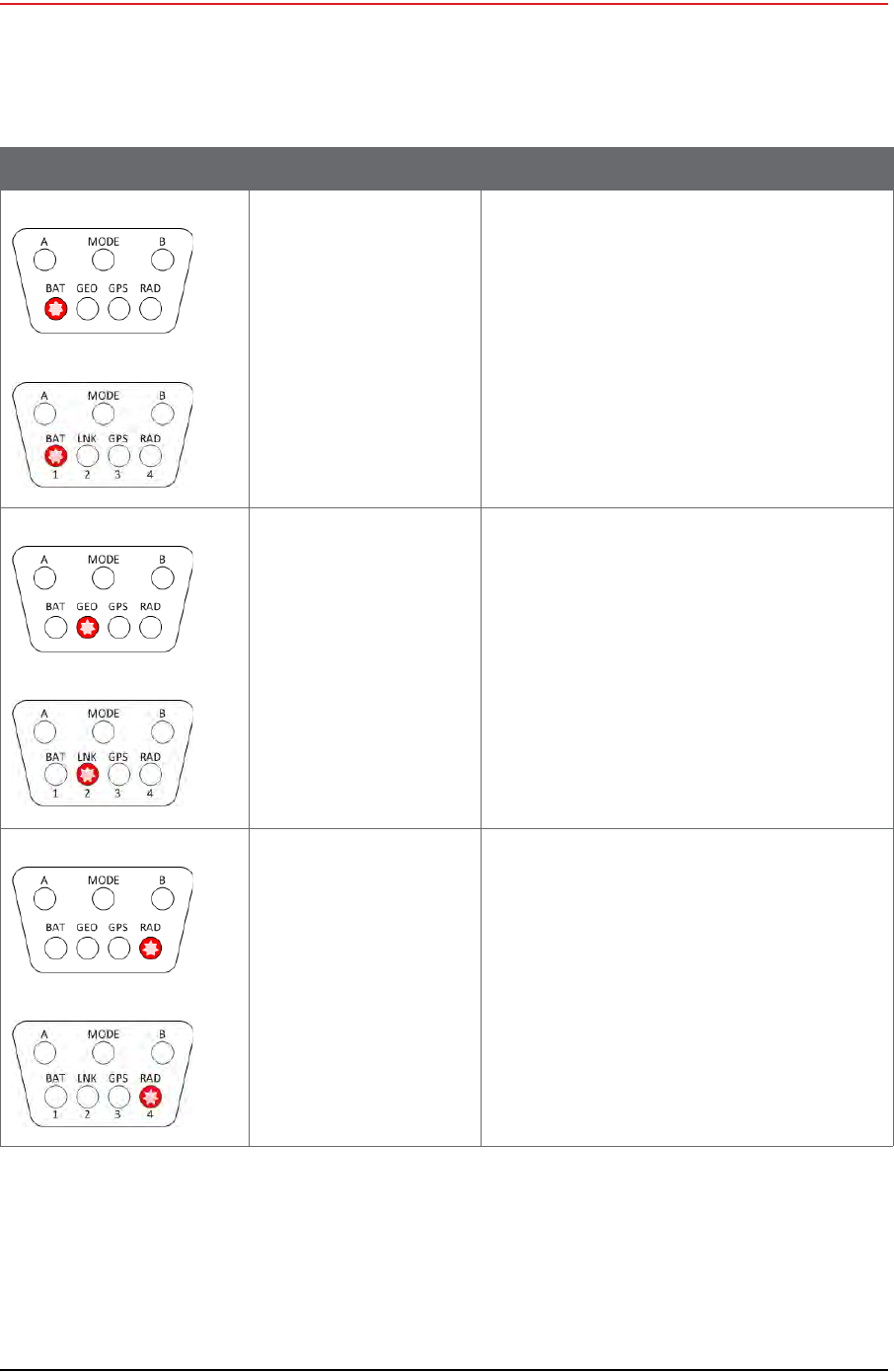
Draft
R01.b RT System 2 v2.3.0 Deployment Guide 179
© 2010-2013 Wireless Seismic, Inc. All rights reserved.
D. LED Indicators
Firmware Upgrade
Firmware upgrade BAT Flashing
The main processor is saving the new firmware for
all processors to non-volatile memory.
The power control
processor's firmware is
being upgraded
GEO/LNK Flashing for approximately 15 seconds
The Radio processor's
firmware is being upgraded RAD Flashing for approximately 1-2 seconds
Table D–11 WRU and LIU LED Status Indications, Firmware Upgrade (cont.)
LED Indicators Summary Description
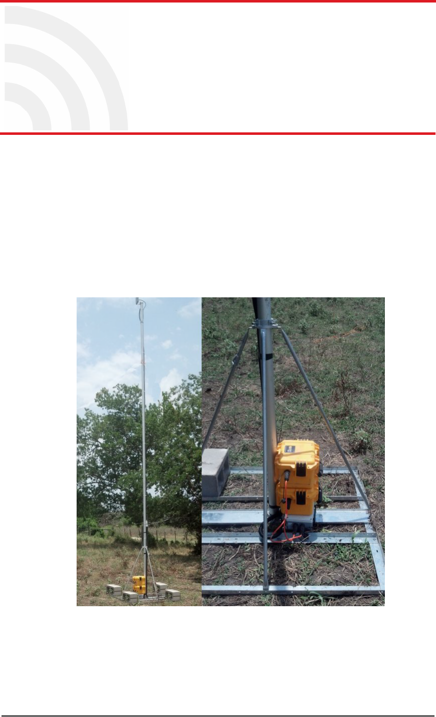
Draft
RT System 2 v2.3.0 180 Deployment Guide R01.b
© 2010-2013 Wireless Seismic, Inc. All rights reserved.
E
E. Weighted Base
This section describes the mast that uses weights to maintain stability.
E.1 Specifications
Tripod Weight = 50 lbs (22.73 kg)
Minimum mast height = 53” (includes 6” for mounting)
Base size = 48” (1.2m) x 48” (1.2m)
Supports up to 12 – 16” x 8” blocks
Pre-galvanized steel frame
Accepts up to 2.5” mast (not included)
Figure E–1 Weighted Mast
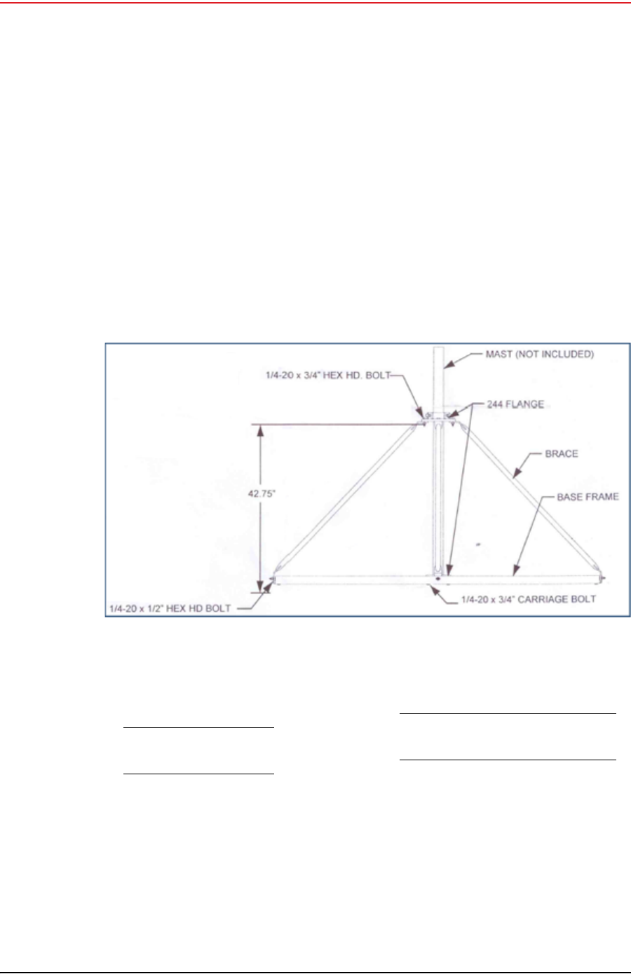
Draft
R01.b RT System 2 v2.3.0 Deployment Guide 181
© 2010-2013 Wireless Seismic, Inc. All rights reserved.
E. Weighted Base
Hardware Supplied
E.2 Hardware Supplied
The following hardware is supplied with the tripod mast:
4 - Bolt, Carriage 1/4 - 20 x 3/4"
12 - Bolt, Carriage 1/4 - 20 x 5/8"
4 - Bolt, 1/4 - 20 x 3/4" Hex Head
4- Bolt, 1/4 - 20 x 1/2" Hex Head
24-Nut, 1/4 - 20
24 - Lock washer, 1/4 Int. tooth
E.3 Assembly Instructions
This section provides instructions and illustrations for assembly of the tripod.
To assemble the tripod:
1Assemble one 244 Flange to the Center Support Plate using four 1/4-20 x 3/4" carriage
Bolts, Lock washers and Hex Nuts. Make sure to assemble the Bolts with the Heads on
the underside of the frame. Hex Nut should be on the top side of the frame.
2 Assemble Base Frame and Center Support Plate using twelve 1/4-20 x 5/8" carriage
Bolts, Lock washers and Hex Nuts. Make sure to assemble the Bolts with the Heads on
the underside of the frame. Hex Nut should be on the top side of the frame.
3Assemble the four (4) Braces to the upper support flange using four 1/4-20x3/4 Hex
Head Bolts, Lock washers and Nuts.
4Assemble the other end of the braces to the base frame using the four (4) 1/4-20 x 1/2"
Hex Head Bolts, Lock washers, and Nuts.
5Insert Bolts into upper and lower flange.
6Slide the mast (not included) into position and tighten securely and weigh.
Wade Antenna Ltd., Ontario, Canada
Figure E–2 Tripod Assembly, Front View
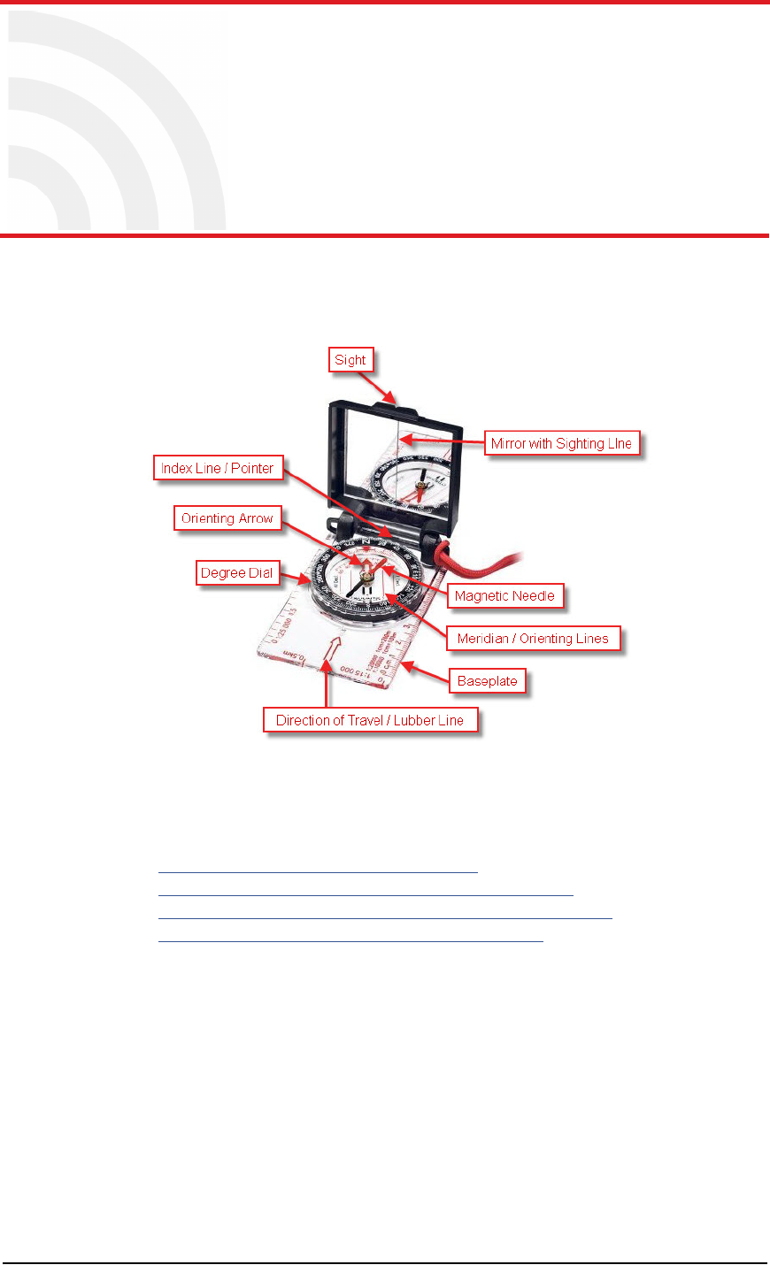
Draft
RT System 2 v2.3.0 182 Deployment Guide R01.b
© 2010-2013 Wireless Seismic, Inc. All rights reserved.
F
F. Using a Compass
This chapter describes how to use a sighting compass. A sighting compass has the same
features as a baseplate compass, but adds a vertical mirror that allows you to view the
compass dial and the landmark at the same time.
For a in-depth descriptions of using a compass with a map and setting the declination on
a compass see the following links:
http://www.compassdude.com/default.shtml
http://www.compassdude.com/compass-declination.shtml
http://www.rei.com/learn/expert-advice/navigation-basics.html
http://www.thecompassstore.com/howtouseyour.html
A compass needle points to the magnetic north pole which is not the same as true or
geographic north. The difference between magnetic and true north is called magnetic
declination. The declination value depends on your actual location on the Earth. Over
time, as the Earth’s magnetic field shifts, the declination values also shift.
Maps are drawn with true north at the top edge. When using a compass to navigate or
locate objects, you must adjust the readings to account for the angular difference
between true north ( ★) and magnetic north (MN). The declination value is marked on
topographical maps as shown in the following figure:
Figure F–1 Sighting Compass (70-0067)
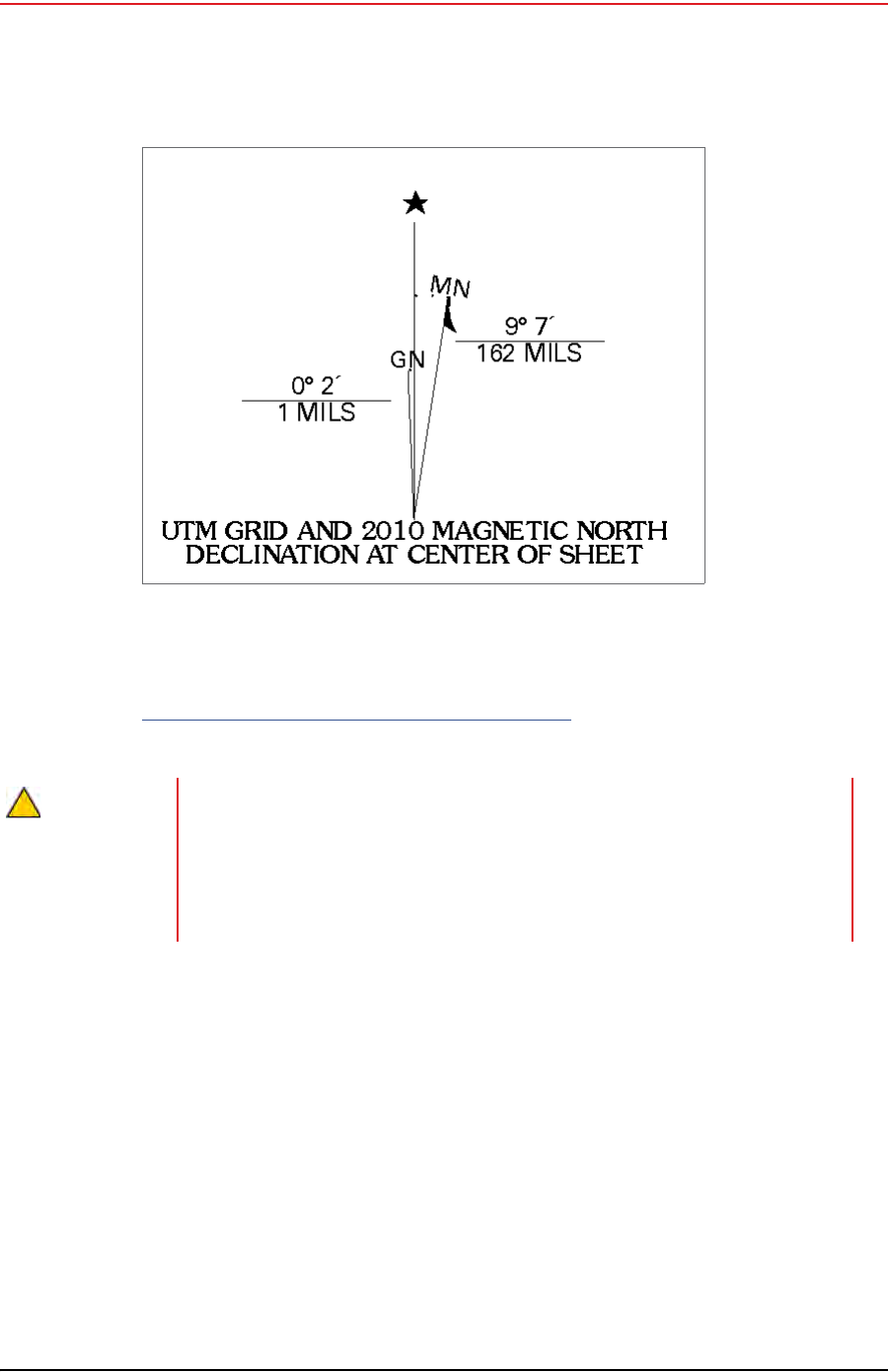
Draft
R01.b RT System 2 v2.3.0 Deployment Guide 183
© 2010-2013 Wireless Seismic, Inc. All rights reserved.
F. Using a Compass
However, because of the dynamic nature of the Earth’s magnetic field, old maps are
inaccurate. To obtain the most recent declination values, enter your map location at the
following link:
http://www.ngdc.noaa.gov/geomag-web/#declination
To locate an object using a map and a compass:
1Place the long edge of the compass baseplate on the map, connecting the desired start
and end points. For example, the start point could be where you are standing [A], and
the end point [B] is where you want to locate the backhaul mast. The Direction of Travel
arrow should point towards the end point (mast location).
2While holding the compass on the map, turn the Degree Dial until the Meridian /
Orienting Lines are parallel with the Meridian lines on the map. This is the same as
turning the Degree Dial until the Orienting Arrow points to north on the map.
Figure F–2 Declination Indication on Map
CAUTION
Placing magnetic objects near a compass can cause an incorrect reading
(deviation). Examples include:
• Objects that contain steel and iron such as pocket knives, belt buckles,
vehicles, railroad tracks, and ore deposits in the Earth
• Objects that use magnets such as stereo speakers
• Electrical current in cables and overhead lines
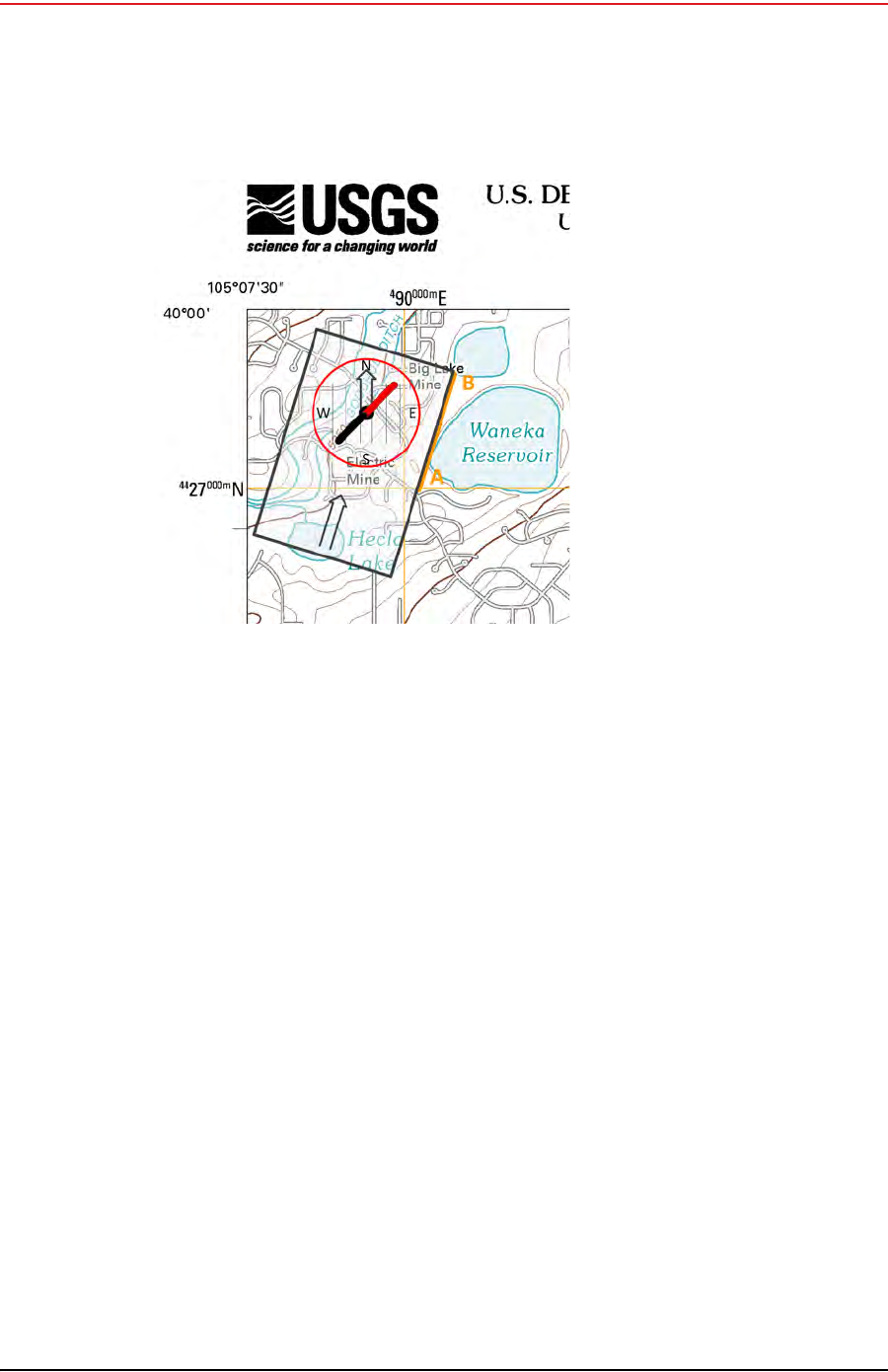
Draft
184 RT System 2 v2.3.0 Deployment Guide R01.b
© 2010-2013 Wireless Seismic, Inc. All rights reserved.
F. Using a Compass
3Adjust for declination.
●If you have an adjustable compass – Move the Orienting Arrow to the right or left by
the declination number. When you align the magnetic needle with the Orienting
Arrow, the declination is accounted for.
●If you do not have an adjustable compass – Mark the declination on your compass
with a piece of tape. Align the magnetic needle with the tape mark.
●Adjust the Orienting Arrow to the left or right. For example:
►For a declination of 0, no adjustment is necessary.
►For a declination of 9 (9 degrees East), move the Orienting Arrow (or place a
tape mark) to the right 9 degrees.
►For a declination of -9 (9 degrees West), move the Orienting Arrow (or place a
tape mark) to the left 9 degrees.
Figure F–3 Compass and Map
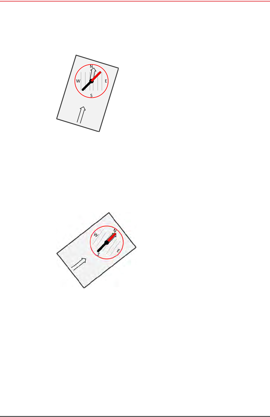
Draft
R01.b RT System 2 v2.3.0 Deployment Guide 185
© 2010-2013 Wireless Seismic, Inc. All rights reserved.
F. Using a Compass
4Pick up the compass and adjust the cover so the angle of the cover to the base is
between 45 and 70 degrees.
5Hold the base of the compass in the palm of your hand. Keep the compass level. Turn
your entire body and the compass until the red end of the Magnetic Needle is aligned
with the red end (north end) of Orienting Arrow.
6While holding the compass at eye level, keep the compass level and align your
destination with the sight notch on the top of the case.
7Ensure that the sighting line in the mirror passes through the center of the compass
wheel.
Figure F–4 Compass Adjusted for
Declination
Figure F–5 Compass Adjusted for
Declination
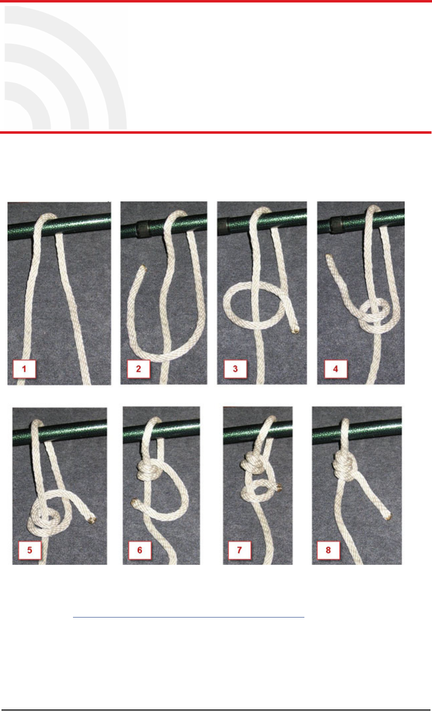
Draft
RT System 2 v2.3.0 186 Deployment Guide R01.b
© 2010-2013 Wireless Seismic, Inc. All rights reserved.
G
G. Rope Knot
This chapter shows how to tie a taut-line hitch knot. This loop knot can be adjusted to
loosen or tighten a line, yet holds under a load. This knot is commonly used to secure
tent lines and loads on vehicles. It is the recommended knot for securing the RT System
2 guy rope mast.
The following link provides a short video example:
http://www.sailingcourse.com/videos/taut_line_hitch.htm
Figure G–1 Tying the Taut-line Hitch Knot

Draft
RT System 2 v2.3.0 187 Deployment Guide R01.b
© 2010-2013 Wireless Seismic, Inc. All rights reserved.
H
H. Country Codes
This chapter provides a quick-reference to the ISO
3166 country codes.
Table H–1 ISO 3166 Country Codes
Name Code
Afghanistan 004
Åland Islands 248
Albania 008
Algeria 012
American Samoa 016
Andorra 020
Angola 024
Anguilla 660
Antarctica 010
Antigua and Barbuda 028
Argentina 032
Armenia 051
Aruba 533
Australia 036
Austria 040
Azerbaijan 031
Bahamas (the) 044
Bahrain 048
Bangladesh 050
Barbados 052
Belarus 112
Belgium 056
Belize 084
Benin 204
Bermuda 060
Bhutan 064
Bolivia, Plurinational
State of 068
Bonaire, Sint Eustatius
and Saba 535
Bosnia and Herzegovina 070
Botswana 072
Bouvet Island 074
Brazil 076
British Indian Ocean
Territory (the) 086
Brunei Darussalam 096
Bulgaria 100
Burkina Faso 854
Burundi 108
Cambodia 116
Cameroon 120
Canada 124
Cape Verde 132
Cayman Islands (the) 136
Central African Republic
(the) 140
Chad 148
Chile 152
China 156
Christmas Island 162
Cocos (Keeling) Islands
(the) 166
Colombia 170
Comoros 174
Congo 178
Table H–1 ISO 3166 Country Codes
Name Code

Draft
H. Country Codes
188 RT System 2 v2.3.0 Deployment Guide R01.b
© 2010-2013 Wireless Seismic, Inc. All rights reserved.
Congo (the Democratic
Republic of the) 180
Cook Islands (the) 184
Costa Rica 188
Côte d'Ivoire 384
Croatia 191
Cuba 192
Curaçao 531
Cyprus 196
Czech Republic (the) 203
Denmark 208
Djibouti 262
Dominica 212
Dominican Republic (the) 214
Ecuador 218
Egypt 818
El Salvador 222
Equatorial Guinea 226
Eritrea 232
Estonia 233
Ethiopia 231
Falkland Islands (the)
[Malvinas] 238
Faroe Islands (the) 234
Fiji 242
Finland 246
France 250
French Guiana 254
French Polynesia 258
French Southern
Territories (the) 260
Gabon 266
Gambia (The) 270
Table H–1 ISO 3166 Country Codes
Name Code
Georgia 268
Germany 276
Ghana 288
Gibraltar 292
Greece 300
Greenland 304
Grenada 308
Guadeloupe 312
Guam 316
Guatemala 320
Guernsey 831
Guinea 324
Guinea-Bissau 624
Guyana 328
Haiti 332
Heard Island and
McDonald Islands 334
Holy See (the) [Vatican
City State] 336
Honduras 340
Hong Kong 344
Hungary 348
Iceland 352
India 356
Indonesia 360
Iran (the Islamic
Republic of) 364
Iraq 368
Ireland 372
Isle of Man 833
Israel 376
Italy 380
Jamaica 388
Table H–1 ISO 3166 Country Codes
Name Code

Draft
H. Country Codes
R01.b RT System 2 v2.3.0 Deployment Guide 189
© 2010-2013 Wireless Seismic, Inc. All rights reserved.
Japan 392
Jersey 832
Jordan 400
Kazakhstan 398
Kenya 404
Kiribati 296
Korea (the Democratic
People's Republic of) 408
Korea (the Republic of) 410
Kuwait 414
Kyrgyzstan 417
Lao People's Democratic
Republic (the) 418
Latvia 428
Lebanon 422
Lesotho 426
Liberia 430
Libya 434
Liechtenstein 438
Lithuania 440
Luxembourg 442
Macao 446
Macedonia (the former
Yugoslav Republic of) 807
Madagascar 450
Malawi 454
Malaysia 458
Maldives 462
Mali 466
Malta 470
Marshall Islands (the) 584
Martinique 474
Mauritania 478
Table H–1 ISO 3166 Country Codes
Name Code
Mauritius 480
Mayotte 175
Mexico 484
Micronesia (the
Federated States of) 583
Moldova (the Republic
of) 498
Monaco 492
Mongolia 496
Montenegro 499
Montserrat 500
Morocco 504
Mozambique 508
Myanmar 104
Namibia 516
Nauru 520
Nepal 524
Netherlands (the) 528
New Caledonia 540
New Zealand 554
Nicaragua 558
Niger (the) 562
Nigeria 566
Niue 570
Norfolk Island 574
Northern Mariana Islands
(the) 580
Norway 578
Oman 512
Pakistan 586
Palau 585
Palestine, State of 275
Panama 591
Table H–1 ISO 3166 Country Codes
Name Code

Draft
H. Country Codes
190 RT System 2 v2.3.0 Deployment Guide R01.b
© 2010-2013 Wireless Seismic, Inc. All rights reserved.
Papua New Guinea 598
Paraguay 600
Peru 604
Philippines (the) 608
Pitcairn 612
Poland 616
Portugal 620
Puerto Rico 630
Qatar 634
Réunion 638
Romania 642
Russian Federation (the) 643
Rwanda 646
Saint Barthélemy 652
Saint Helena, Ascension
and Tristan da Cunha 654
Saint Kitts and Nevis 659
Saint Lucia 662
Saint Martin (French
part) 663
Saint Pierre and
Miquelon 666
Saint Vincent and the
Grenadines 670
Samoa 882
San Marino 674
Sao Tome and Principe 678
Saudi Arabia 682
Senegal 686
Serbia 688
Seychelles 690
Sierra Leone 694
Singapore 702
Table H–1 ISO 3166 Country Codes
Name Code
Sint Maarten (Dutch
part) 534
Slovakia 703
Slovenia 705
Solomon Islands (the) 090
Somalia 706
South Africa 710
South Georgia and the
South Sandwich Islands 239
South Sudan 728
Spain 724
Sri Lanka 144
Sudan (the) 729
Suriname 740
Svalbard and Jan Mayen 744
Swaziland 748
Sweden 752
Switzerland 756
Syrian Arab Republic
(the) 760
Taiwan (Province of
China) 158
Tajikistan 762
Tanzania, United
Republic of 834
Thailand 764
Timor-Leste 626
Togo 768
Tokelau 772
Tonga 776
Trinidad and Tobago 780
Tunisia 788
Turkey 792
Turkmenistan 795
Table H–1 ISO 3166 Country Codes
Name Code

Draft
H. Country Codes
R01.b RT System 2 v2.3.0 Deployment Guide 191
© 2010-2013 Wireless Seismic, Inc. All rights reserved.
Turks and Caicos Islands
(the) 796
Tuvalu 798
Uganda 800
Ukraine 804
United Arab Emirates
(the) 784
United Kingdom (the) 826
United States (the) 840
United States Minor
Outlying Islands (the) 581
Uruguay 858
Uzbekistan 860
Vanuatu 548
Venezuela, Bolivarian
Republic of 862
Viet Nam 704
Virgin Islands (British) 092
Virgin Islands (U.S.) 850
Wallis and Futuna 876
Western Sahara* 732
Yemen 887
Zambia 894
Zimbabwe 716
Table H–1 ISO 3166 Country Codes
Name Code

Draft
RT System 2 v2.3.0 192 Deployment Guide R01.b
© 2010-2013 Wireless Seismic, Inc. All rights reserved.
I
I. Français
Ce chapitre fournit des informations sur le suivant :
“Batteries” sur la page 192
“l'information juridique” sur la page 198
I.1 Batteries
Ce chapitre fournit des informations sur les batteries utilisées dans le système
RT System 2 de Wireless Seismic, Inc.
I.1.1 Batteries au lithium-ion
Cette section fournit des informations sur les caractéristiques, l'utilisation et la
manipulation des batteries au lithium-ion. Reportez-vous aux sections suivantes pour en
savoir plus:
●“Spécifications” on page 192
●“Directives en matière de manipulation et de sécurité” on page 193
●“Transport” on page 194
●“Entreposage” on page 196
I.1.1.1 Spécifications
Le RT System 2 utilise une ou deux batteries au lithium-ion intelligentes et
personnalisées, dotées d'un circuit de charge autonome qui protège les batteries contre
les surcharges, décharges, courts-circuits ou changements extrêmes de température.
Le tableau suivant indique les spécifications des batteries:
Tableau I–1 Spécifications des batteries au lithium-ion
Élément Description Valeur
Tension Nominale 3,7 V c.c.
Arrêt 2,8 V c.c.
Charge complète (90 %) 4,1 V c.c.
Tension de charge excessive 4,28 V c.c.
Tension de décharge
excessive 2,80 V c.c.
Courant Courant de charge maximum 2 A
Consommation, mode actif 4,2 mA maximum
Consommation, mode veille 66 A maximum
Charge complète (90 %)
mAh Environ 12 000 mAh à la
tension nominale

Draft
R01.b RT System 2 v2.3.0 Deployment Guide 193
© 2010-2013 Wireless Seismic, Inc. All rights reserved.
I. Français
Batteries
I.1.1.2 Directives en matière de manipulation et de sécurité
Respecter les directives suivantes en matière de manipulation et de sécurité :
Si un bloc-batterie présente une fuite de liquides, ne pas toucher les liquides. Jeter le
bloc-batterie en cas de fuite. En cas de contact oculaire avec du liquide, ne pas se frotter
les yeux. Rincer immédiatement les yeux avec de l'eau pendant au moins 15 minutes, en
soulevant les paupières supérieures et inférieures jusqu'à ce qu'il n'y ait plus de trace de
liquide. Consulter un médecin.
Ne pas démonter, écraser ou percer une batterie
Ne pas court-circuiter les contacts externes d'une batterie
Ne pas jeter une batterie dans le feu ou l'eau
Ne pas exposer une batterie à des températures supérieures à 60 °C (140 °F)
Maintenir la batterie à l'écart des enfants
Éviter d'exposer la batterie à des vibrations ou chocs excessifs
Ne pas utiliser une batterie endommagée
Les blocs-batteries au lithium-ion DOIVENT être entièrement déchargés avant leur
élimination
Charge complète (90 %)
mWh Environ 44 400 mWh à la
tension nominale
Capacité 48,8 wattheures
Connecteur 5 broches
DEL Une DEL qui indique l'état de
charge lors de la connexion à
la station de charge, de la
manière suivante :
•Vert : chargé
•Rouge : en train de
charger
• Orange : phase
transitionnelle entre l'état
de chargement et l'état
chargé, ou dépassement
des limites de la
température de charge
Étiquette Une étiquette indiquant le
numéro de série sous forme
de code à barres
Température Fonctionnement De -40°C à +85°C
Chargement De -5°Cà+45°C
Entreposage à température
ambiente • De -20°C à +45°C durant
une période maximum
d'un mois
• De -20°C à +35°C durant
6 mois maximum ; passé
ce délai, les blocs-
batteries doivent être
rechargés à plus de 50 %
de leur capacité
Tableau I–1 Spécifications des batteries au lithium-ion (cont.)
Élément Description Valeur

Draft
194 RT System 2 v2.3.0 Deployment Guide R01.b
© 2010-2013 Wireless Seismic, Inc. All rights reserved.
I. Français
Batteries
Bien qu'il puisse exister des restrictions locales ou nationales, les batteries au lithium-ion
sont considérées comme des « déchets universels non dangereux » par le gouvernement
fédéral. Il existe des restrictions qui s'appliquent à ceux qui gèrent de grandes quantités
de déchets universels ; celles-ci définissent l'étiquetage, le confinement, etc. Dans la
mesure du possible, les batteries doivent être déchargées avant de les jeter. Les
conducteurs/contacts de batterie doivent être fixés de manière à éviter un court-circuit
accidentel. Chaque bloc-batterie doit être placé dans un sac en plastique.
Le recyclage est encouragé lorsqu'il est réalisable. Les batteries contiennent des
matériaux recyclables et sont acceptées par plusieurs entreprises de recyclage de
batteries. Reportez-vous à l'un des éléments suivants pour obtenir plus d'informations
sur le recyclage et l'élimination :
●http://www.swe.com
●http://www.rbrc.org
●http://www.call2recycle.org
●1-800-8-BATTERY
●1-877-2-RECYCLE
I.1.1.3 Transport
Aux États-Unis, les expéditions de grandes quantités de batterie au lithium-ion (plus de 24
piles ou 12 batteries par colis) sont réglementées comme des matières dangereuses (classe
9) par le gouvernement fédéral et sont soumises aux règlements décrits ci-après :
Code of Federal Regulations, Title 49 Transportation.
http://ecfr.gpoaccess.gov/cgi/t/text/text-
idx?sid=92868a82add6feba6afa796572133179&c=ecfr&tpl=/ecfrbrowse/Title49/
49tab_02.tpl
International Air Transport Association (IATA)
http://www.iata.org/whatwedo/cargo/dangerous_goods/pages/lithium_batteries.aspx
Les batteries ne peuvent être expédiées par voie terrestre que si toutes les conditions
suivantes sont satisfaites :
La boîte utilisée satisfait le test de chute de 1,2 m (boîte classée « UN ») de boîte
d'emballage
Les bornes de bloc-batterie sont protégées pour éviter un court-circuit
Le poids brut ne dépasse pas 30 kg (66 livres)
L'emballage extérieur porte l'étiquette requise en vigueur. La figure suivante en montre
un exemple.
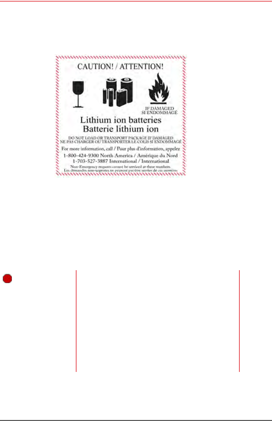
Draft
R01.b RT System 2 v2.3.0 Deployment Guide 195
© 2010-2013 Wireless Seismic, Inc. All rights reserved.
I. Français
Batteries
Les batteries ne peuvent être expédiées par voie aérienne que si toutes les conditions
suivantes sont satisfaites :
La boîte utilisée satisfait le test de chute de 1,2 m (boîte classée « UN ») de boîte
d'emballage
Les bornes de bloc-batterie sont protégées pour éviter un court-circuit
Le poids brut de chaque colis ne dépasse pas 10 kg (22 livres)
L'emballage extérieur porte l'étiquette requise en vigueur. La figure précédente en
montre un exemple (“Example Battery Shipping Label” on page 195).
Exemple I–1 Example Battery Shipping Label
AVERTISSEMENT
Les informations contenues dans le présent document ont pour
but de fournir une connaissance générale des règlements
s'appliquant aux batteries. Elles ne sont pas exhaustives, et les
conditions mentionnées dans ce document peuvent avoir
changées. Rien dans le présent chapitre ou dans le Guide de
déploiement ne constitue un avis juridique ou est destiné à
répondre aux problèmes juridiques, de conformité, ou
réglementaires spécifiques qui peuvent survenir dans des
circonstances particulières. Le présent chapitre et le Guide de
déploiement ne sont pas destinés à remplacer les règlements
officiels en vigueur concernant l'emballage et l'expédition de
matières dangereuses ou un conseil juridique indépendant sur
c es questions. Vous êtes seul responsable du respect de
toutes les lois, règlements et autres exigences. Veuillez vous
reporter à une copie officielle de la version en vigueur de ces
documents pour obtenir les dernières informations.

Draft
196 RT System 2 v2.3.0 Deployment Guide R01.b
© 2010-2013 Wireless Seismic, Inc. All rights reserved.
I. Français
Batteries
I.1.1.4 Entreposage
Un entreposage et un entretien adéquats des batteries au lithium-ion est indispensable pour
optimiser leur durée de vie utile et éviter une défaillance catastrophique. Respecter les
précautions suivantes en matière d'entreposage :
Retirer les batteries de l'unité distante sans fil avant l'entreposage
Température d'entreposage recommandée des batteries au lithium-ion :
●De -20°C à +45°C durant une période maximum d'un mois
●De -20°C à +35°C durant 6 mois maximum ; passé ce délai, les blocs-batteries
doivent être rechargés à plus de 50 % de leur capacité
●L'entreposage à basses températures ralentit la décharge naturelle et la perte de
capacité au fil du temps. Entreposer les batteries à 25°C ou moins si possible
Niveaux de charge d'entreposage recommandés :
●Charger (ou décharger) les batteries à un niveau de charge de 30 % à 50 % avant
de les entreposer. Des niveaux de charge inférieurs ou supérieurs peuvent réduire la
durée de vie des batteries.
●Ne jamais entreposer des batteries entièrement déchargées, sauf en cas
d'élimination.
●Un chargement périodique est nécessaire pour maintenir une charge de 30 % à 50 %
en cas d'entreposage de longue durée
Entreposer les batteries dans un endroit bien aéré
Ne pas laisser les batteries inutilisées pendant de longues durées, qu'elles soient dans le
produit ou placées en entreposage. Si une batterie n'a pas été utilisée pendant 6 mois,
vérifier l'état de charge et charger ou éliminer la batterie, le cas échéant.
Vérifier régulièrement l'état de charge de la batterie
Envisager le remplacement de la batterie par une nouvelle en cas de constat d'une des
conditions suivantes :
●L'autonomie de la batterie descend en dessous d'environ 80 % de son autonomie
initiale
●Le temps de charge de la batterie augmente sensiblement
I.1.2 Chargement des batteries au lithium-ion
Cette section décrit les précautions de chargement et présente le chargeur de batterie.
I.1.2.1 Précautions de chargement
Respecter les précautions de chargement suivantes :
Avant de la charger, inspecter la batterie pour détecter les signes éventuels de
dommages sur le boîtier ou les connecteurs susceptibles de créer un court-circuit.
La batterie peut être chargée dans la plage de température de 0°Cà+45°C. En cas de
chargement de la batterie en dehors de cette plage, la batterie peut devenir très chaude
ou se rompre.
Être absolument sûr de l'utilisation d'une source de 5 V lors du chargement de la
batterie.
Prendre soin de charger les batteries sur une surface ininflammable.
Ne pas charger les batteries à proximité d'objets ou de liquides inflammables.
Conserver un extincteur à poudre chimique de classe C à proximité.
Ne pas continuer de recharger la batterie si elle ne se recharge pas dans le temps de
chargement spécifié.
NE JAMAIS laisser une batterie au lithium-ion sans surveillance lorsqu'elle est en train de
charger.
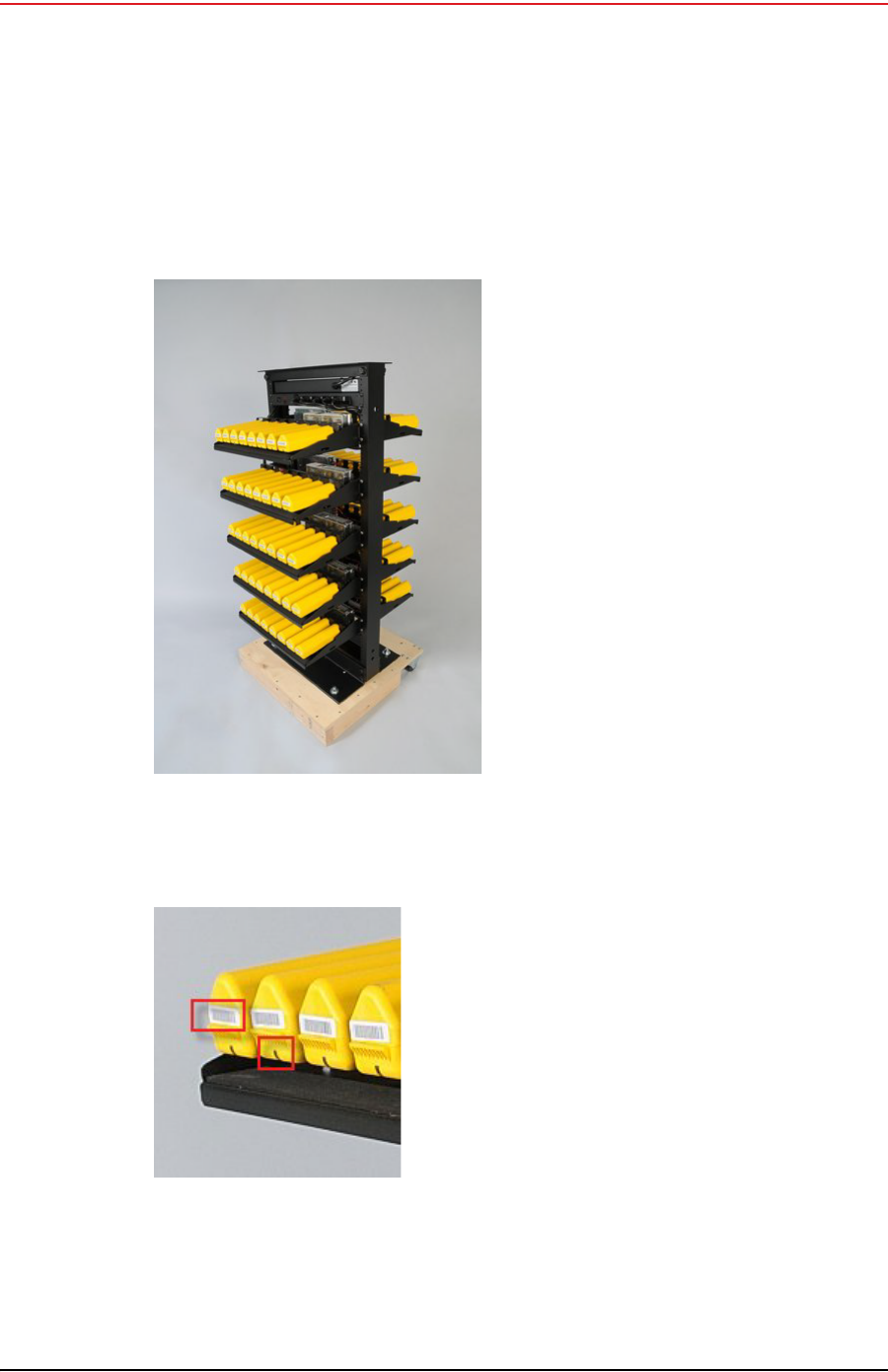
Draft
R01.b RT System 2 v2.3.0 Deployment Guide 197
© 2010-2013 Wireless Seismic, Inc. All rights reserved.
I. Français
Batteries
I.1.2.2 Chargeur de batterie
Le chargeur de batterie au lithium-ion est conçu pour fonctionner à partir d'une ligne de
service simple 120 V c.a., 10 A.
Le bloc d'alimentation servant à charger le bloc-batterie fournit une tension régulée de 5 V
c.c.
Exemple I–2 Chargeur de batterie
Exemple I–3 Étiquette avec
numéro de série et voyant
DEL

Draft
198 RT System 2 v2.3.0 Deployment Guide R01.b
© 2010-2013 Wireless Seismic, Inc. All rights reserved.
I. Français
l'information juridique
I.2 l'information juridique
I.2.1 Conformité avec les règles et règlements de la FCC
La Federal Communications Commission (FCC) règlemente l'utilisation d'antennes dans
l'article suivant : Code of Federal Regulations – Title 47, Part 15 – Radio Frequency Devices,
Subpart C – Intentional Radiators, Section 15.203 Antenna Requirement.
Lorsqu'il est utilisé comme prévu, le RT System 2 respecte les conditions de l'article 15.203
de la FCC de la manière suivante :
Lorsqu'il est utilisé comme prévu, le RT System 2 respecte les conditions de l'article 15.203
de la FCC et d'Industrie Canada CNR-Gen 7.1.2 de la manière suivante :
Les antennes du RT System 2 doivent être installées et manipulées par des
professionnels spécifiquement désignés pour cela.
Les changements ou modifications non expressément approuvés par Wireless Seismic,
Inc. peuvent annuler l'autorisation de l'utilisateur d'utiliser l'équipement.
Le RT System 2 doit être utilisé uniquement avec les antennes fournies (Tableau I–2)
branchées à l'unité distante sans fil ou à la station de base à l'aide d'un connecteur mâle
de type N intégré.
PRUDENCE
Le risque d'explosion si la batterie est remplacée par un type incorrect.
Débarrassez-vous utilisé batteries selon les instructions.
REMARQUE
Cet équipement a été testé et jugé conforme aux limites fixées pour un appareil
numérique de classe A, conformément à la partie 15 des règles de la FCC. Ces
limites sont conçues pour fournir une protection raisonnable contre les
interférences nuisibles lorsque l'équipement est utilisé dans un environnement
commercial. Cet équipement génère, utilise et peut émettre l'énergie des
fréquences radio et, s'il n'est pas installé et utilisé conformément au mode
d'emploi, peut causer des interférences nuisibles avec les communications
radio. Le fonctionnement de cet équipement dans une zone résidentielle est
susceptible de provoquer des interférences nuisibles, auquel cas l'utilisateur
devra corriger les interférences à ses propres frais.
Tableau I–2 Spécifications des antennes
Modèle Fréquence
(MHz) Gain Largeur de
bande
verticale Poids Dimensions
(Longueur x
Diamètre)
WSI 65-0204
(antenna-normal) 2400 5.5 dBi 25° 0.4 lbs
.2 kg 32 x 0,6 po
810.5 x 15 mm
WSI 65-0091
(extension-normal) 2400 0 dBi N/A 0.6 lbs
0.3 kg 30 x 0,7 po
762 x 18,5 mm

Draft
R01.b RT System 2 v2.3.0 Deployment Guide 199
© 2010-2013 Wireless Seismic, Inc. All rights reserved.
I. Français
l'information juridique
L'autorisation d'équipement de FCC a été accordée comme suit :
Le 5Mbps unité d'interface de ligne a reçu l'autorisation d'équipement.
Le 5Mbps unité lointaine sans fil a reçu l'autorisation d'équipement.
I.2.2 Industrie Canada Conformité
L'unité distante sans fil a reçu l'approbation et la certification d'Industrie Canada (IC) par
rapport à CNR-210 8e édition et CNR-102 4e édition :
Cet appareil numérique de la classe A est conforme à la norme NMB-003 du Canada.
L'unité d'interface de ligne a reçu l'approbation et la certification d'Industrie Canada (IC) par
rapport à CNR-210 8e édition et CNR-102 4e édition :
Cet appareil numérique de la classe A est conforme à la norme NMB-003 du Canada.
Cet appareil est conforme avec I'industrie Canada licence exemptes des normes. Son
fonctionnement est soumis aux deux conditions suivantes :
Ce dispositif ne peut causer des interférences, et
Ce dispositif doit accepter toute interférence, y compris les interférences qui peuvent
causer un mauvais fonctionnement du dispositif.
I.2.3 Acquiescement de CE
L'Unité Lointaine Sans fil (WRU) et l'Unité d'Interface de Ligne (LIU) se plie aux directives
d'UE applicables pour le Conformité Européene (CE) la marque. La marque suivante est
attachée à chaque unité.
AVERTISSEMENT
Afin de se conformer aux normes de la matière d'exposition aux
radiofréquences (RF), les unités RT System 2 doivent être installées de
manière à garder en permanence une distance minimale de 20 cm entre la
ou les antennes et le corps de toute personne en mode de fonctionnement
normal.
Exemple I–4 Marque de CE

Draft
RT System 2 v2.3.0 200 Deployment Guide R01.b
© 2010-2013 Wireless Seismic, Inc. All rights reserved.
Index
Numerics
12 V DC 36
19 dBi directional antenna 147
5.8 GHz band 35
56-0032 INTL 68
56-0035 US 68
6 dBi antenna 147
65-0091 18
90-0026 10
90-0028 10
90-0032 10
90-0039 10
A
access point radio 64
Acquiring GPS fix 167
antenna
attach 18
bracket 53
connecting 18
extender 18
extenders 11
specifications 36, 41, 143
antennas 36, 143
radio 41
armored cable 56
assemble
the backhaul 47
the ground equipment 16
auto-power-leveling 36
B
B 167, 173
backhaul 23, 28
components 28
masts 46
power requirements 36
Backpack Kit 28
base 46, 48
tips 47
batteries
attach 16
battery
charge time 12
charger 140
charger location 12
charging 140
failure 177
fuse test failure 164
handling and safety guidelines 137
latch 16
remove 134
shipments 138
specifications 136
storage 139
Battery A in use 170, 171
Battery B in use 170, 171
battery failure 177
browser pop-ups 119
Bucket Brigade 23
C
cable
Armored Ethernet 42
clamp 52
Ethernet 42
LIU to Battery 42
LIU to NanoStation radio 42
LIU-to-PC 42
RF Extender 42
Shielded Ethernet 42
cables 56, 60
central 28
clamps 60
color-coded 64
compass 182
contact 10
Continue 166
country codes for radios 68
CSS 24
custom number of recorder radios 117
D
data flow 25
declination 182
deploy
at actual location 14
deviation 183
disassemble the WRU 134
discharge 136
discover and configure the radios 68, 104
Dummy Batteries 11
E
elbow connector 56
Elevation Profile 75, 111
error
Geophone failure 167
indicators 161
No GPS fix 167
No neighbor detected 168
Self test failure 172
Error LEDs 166
Ethernet cable
non-powered 78
powered 78
extreme temperature charging 136
F
FCC 143
Section 15.203 143
Fiber Backhaul Kit 29, 42
fiber cables 65
fiber optic cable 35
figure
Tripod Assembly – Front View 181
final speed test 117
firmware
upgrade 179
Formed 176
four-line, dual-backhaul line 26
frequency
International 68
United States of America 68
fuse test failure 164

Draft
Index
G
R01.b RT System 2 v2.3.0 Deployment Guide 201
© 2010-2013 Wireless Seismic, Inc. All rights reserved.
G
geographic north 182
geophone 17
Geophone test in progress 166
Global Mapper 75
Google Earth 75, 111
GPS acquire position 21
antenna 56
disciplined 175
error 167
LED flashing 21
lock 21, 175
lock, not disciplined 178
no discipline 177
no lock 178
green-to-green 56
ground 60
equipment 11
wire 56, 60
ground equipment
assemble 16
guy lines 57, 58
ring 51, 52, 53
H
help 10
hopping 23
hose clamp 49
I
Industrial, Scientific, and Medical radio band 24
Industry Canada RSS-Gen 7.1.2 143
install and troubleshoot the radios 76
ISM 24
ISO 3166-1 68
L
LED dead batteries 162, 164, 170, 171
reset pattern 174
sleeping 162, 164, 170, 171
status 161
undeployed 162, 164, 170, 171
line radio 36, 49
kit 29
line station 28
LIU 35
A, flashing 177
A, solid 175, 176
all off 173
B, flashing 177
B, solid 175, 176
BAT, flashing 176, 177
BAT, solid 176
Disciplined to GPS 175
GPS, flashing 175, 176, 177
GPS, off 178
GPS, solid 175, 178
hard reset 174
LEDs 173
LNK, flashing 176, 177
LNK, off 177
LNK, solid 175, 176
MODE, flashing 175, 176, 177
MODE, solid 175
power on LED rotation 174
RAD, flashing 176
RAD, solid 176
LIU connected to Central 175
LIU Kit 28
locate an object using a map and a compass 183
loop knot 186
M
magnetic
north 182
objects near a compass 183
mast 46, 48, 58, 59, 180
assemble 51
collar 57
kit 28
masts 46
modifications 143
N
Neighbor
discovered 167
discovery in progress 167
no communications with Central 177
GPS discipline 177
GPS lock 178
IP Address 177
node 23
O
obstructions 47
one recorder, multiple line station radios 115
overcharge 136
P
pendant link 69
pendant radio connection 94
pendant radio link connections 93
PoE 24
injector 24
switch 24
Point-to-Multipoint 23
Point-to-Point 23
pole pairs 64
power off WRU 133
Power over Ethernet 24
power-leveling 36
private network 69, 105
R
radio
Access Point (A) 64
configuration 67
configuration files 68, 104
configure 115
country codes 68
create an Elevation Profile 75
credentials 72
default IP Address 71
error message 68
frequencies 103
install and troubleshoot 113
label 64
link to recording truck 69
location plan 74
multiple line station 115
one recorder 115
pairs 64
prepare 67, 102
recorder 117
redundant recorder 116
replacing 88
set power level 95

Draft
Index
S
202 RT System 2 v2.3.0 Deployment Guide R01.b
© 2010-2013 Wireless Seismic, Inc. All rights reserved.
shielding 83
speed test 78
Station (S) 64
upload configuration file 73
upload new firmware 88
version 67
versions 103
recorder 28
radio 40
Recorder Radio Kit 30, 31
recording truck 28
recording truck connection
fiber cable 90
optimal angle pendant to line 92
radio link (pendant) 91
redundant recorder radio 116
relay 23
remote 28
remove battery 134
repeater 19
rolling the backhaul 84
run the speed test 80, 118
S
self test 166
fails 22
failure 21
in progress 166
set the PN radio power level 95
short circuit 136
single-backhaul line 25
skip a self-test 22
a test 166
slope 47
specifications
antenna 36, 41, 143
stakes 49, 58
star configuration 23, 27
static IP address 69
station radio 64
status
Acquiring GPS fix 167
Battery A in use 170, 171
Battery B in use 170, 171
Continue 166
Geophone test in progress 166
Neighbor discovered 167
Neighbor discovery in progress 167
self test in progress 166
Undeployed 162, 170, 171
String-of-Pearls 23
supported
antennas 36, 41, 143
Surge Protector 31, 41, 56, 57
ground wire 60
T
THD test failure 167
tie a taut-line hitch knot 186
tripod assembly 181
true north 182
U
Ubiquiti Discovery Tool 68, 104
download 70
undeploy the WRU 133
undeployed 133, 162, 170, 171
unzip
7-Zip 89, 127
Windows 7 89, 127
upload new firmware 126
upload new radio firmware 88
users 10
W
white-to-white 56
wind 48
WRUA, flashing 167, 170, 171, 173
A, solid 164
B, flashing 167, 170, 171, 173
B, solid 165
BAT, flashing 166, 179
BAT, solid 164, 165, 172
GEO, flashing 166, 179
GEO, solid 166, 167, 172
GPS, flashing 166, 167
GPS, solid 166, 167, 172
hard reset 163, 169
MODE, flashing 166, 167, 173
MODE, solid 166, 178
no LEDs 162, 164, 170, 171
power off 133
power on 19
power on LED rotation 163, 169
RAD, flashing 166, 167, 179
RAD, solid 168, 172
tests 21