Wireless N2-4XE1-5G7 Point to Point Data Transceiver User Manual Test report updated per 14 April FCC email
Wireless Inc Point to Point Data Transceiver Test report updated per 14 April FCC email
Wireless >
Contents
- 1. User manual
- 2. user manual revision page
- 3. Test report updated per 14 April FCC email
Test report updated per 14 April FCC email
Wireless Inc. FCC ID: EV9N2-4XE1-5G7
1 of 16
EXHIBITS
EXHIBIT 1: Letter Requesting Confidentiality under Sec. 0.457(d)
EXHIBIT 2: Product Description and Operation Overview
EXHIBIT 3: Information for which Confidentiality is Requested
Schematics
EXHIBIT 4: Product Photographs
EXHIBIT 5: User Manual and FCC ID Label
EXHIBIT 6: RF Hazard Information per Sec. 1.1307
EXHIBIT 7: Report of Measurements
Wireless Inc. FCC ID: EV9N2-4XE1-5G7
2 of 16
EXHIBIT 1: Letter Requesting Confidentiality under Sec. 0.457(d)
- refer to separate Word attachment

Wireless Inc. FCC ID: EV9N2-4XE1-5G7
3 of 16
EXHIBIT 2: Product Description and Operation Overview
General Overview
The N2-4XE1 is a point to point Wireless Extension operating in the 5.3/5.7 GHz UNII band as
authorized in rule sections 15.401 through 15.407.The unit is enclosed in a weather proof
outdoor enclosure and is intended to provide data links over distances up to 10 km.The radio
in the unit operates full duplex, transmitting and receiving data at the rate of 8.448 Mbps. The
radio is modulated using BPSK.
The product uses two separate 100 MHz bands within the U-NII frequency spectrum. Within
these bands,the N2-4XE1 series operates in one of many independent channels providing for
frequency reuse and network flexibility.
Synthesized RF channel selection is field configurable,as are the power output options for the
selection of antenna sizes..
Frequency Band: Full-duplex operation in the UNII band
Frequency Range: 5,250 -5,350 MHz and 5,725 -5,825 MHz
Digital Interface
Capacity Options:4xE1
ITU-T/E1
Type:Based on 4 E-1 inputs
Line rate:4 x 2.048 Mb/s
Line Code:HDB3
Interface:75 unbalanced or optional 120 unbalanced
Connectors:BNC (75 )or RJ-48C (120 )
5.3 GHz RX( Low Band) 5.7 GHz TX (High Band)
Frequency Range: 5,250 -5,350 MHz 5,725 -5,825 MHz
Output power: 0 dBm 0 dBm
+4 dBm +4 dBm
+8 dBm +8 dBm
+12 dBm +12 dBm
A description of the theory of operation and product configuration is found in an attachment to
this application and report.
Wireless Inc. FCC ID: EV9N2-4XE1-5G7
4 of 16
System Interconnection
- refer to attachment fccbloc.pdf
Wireless Inc. FCC ID: EV9N2-4XE1-5G7
5 of 16
EXHIBIT 3: Information for which Confidentiality is Requested
Schematics
Wireless Inc. FCC ID: EV9N2-4XE1-5G7
6 of 16
EXHIBIT 4: Product Photographs
-refer to separate jpg attachments
Wireless Inc. FCC ID: EV9N2-4XE1-5G7
7 of 16
EXHIBIT 5: User Manual and FCC ID Label
-refer to separate .pdf attachment
Wireless Inc. FCC ID: EV9N2-4XE1-5G7
8 of 16
EXHIBIT 6: RF Hazard Information Per Sec. 1.1307
For transmitters operating in the 5250-5825 MHz frequency range, paragraph 1.1310 limits
maximum permissible exposure (MPE) to 1 mW/cm2 for uncontrolled environments.
The maximum distance from the antenna at which MPE is met or exceeded is calculated from the
equation relating field strength in V/m, transmit power in watts, transmit antenna gain, and
separation distance in meters:
E,V/m = (√(30*P*G))/d
Power density, mW/m2 = E2/3770
E for MPE 1mW/m2 = 61.4 V/m
Simplifying and rearranging terms:
d = (√(30*P*G))/61.4 Converting to decibels:
20 log d = 10 log 30 + 10 log P watts + G dBi -35.8 dB
20 log d = 14.77 + PdBm - 30 dB -35.8 + GdBi
20 log d = P dBm + G dBi -51 ; d = 10^(PdBm+GdBi-51)/20
EUT 26 dB bandwidth: 11.4 MHz
Maximum allowed EUT output power: 17 dBm + 10 log(11.4) = 27.6 dBm
Defacto EIRP limit: 27.6 dBm + 23 dBi = 50.6 dBm EIRP
EUT design maximum output: 12 dBm
Maximum EIRP = 12+23 = 35 dBm EIRP
MPE for 35 EIRP = 10^(27.7-51)/20 = 16 cm
Instructions will be placed in the user manual instructing installers and users to maintain a
minimum distance of 20 cm during operation of the EUT.
Wireless Inc. FCC ID: EV9N2-4XE1-5G7
9 of 16
EXHIBIT 7: Report of Measurements
Wireless Inc. FCC ID: EV9N2-4XE1-5G7
10 of 16
FCC CERTIFICATION INFORMATION
The following information is in accordance with FCC Rules, 47CFR Part 2.
2.1033(b)1 Applicant: Wireless Inc.
5452 Betsy Ross Drive
Santa Clara CA 95054-1101
2.1033(b)2 FCC ID: EV9N2-4XE1-5G7
2.1033(b)3 Installation instructions are found in attached document.
2.1033(b)4 A brief description of the circuit functions is found in attached
document
2.1033(b)5 Block diagram is found in attached document
2.1033(b)6 Report of measurements is found below.
2.1033(b)7 Product photographs are attached in JPEG format.
2.1033(b)8 The EUT is operated with accessory devices described below and
in the attachments submitted.
2.1033(b) 9 NOT APPLICABLE
2.1033(b)10 - 12 NOT APPLICABLE
15.203 The Wireless UNII radio will be professionally installed. At present, there are
four antennas specified for use with the radio:
Gabriel SSP2-52ARI 28.5 dBi dish
MTI Technology MT 30102 23 dBi flat panel array
Radiowaves SP1-5.2NL 26 dBi dish
Gabriel DFPD.5-52 18 dBi flat panel array

Wireless Inc. FCC ID: EV9N2-4XE1-5G7
11 of 16
SUMMARY OF TEST RESULTS
15.407 General Technical Requirements
The UNII requirements for maximum power, peak power spectral density, minimum
26 dB emissions bandwidth, and maximum EIRP are interdependent variables. In
addition, the level of transmitter spectral re-growth at the UNII band edges will limit the
power output that may be transmitted into a particular antenna, since the emission limit is
-17dBm/MHz and /or -27dBm/MHz EIRP, dependent on both antenna gain and power input.
The Wireless UNII radio has user programmable output power levels from 0 - 12 dBm.
The 26 dB channel bandwidth is 11.4 MHz.
A number of antennas can be used with the point-to-point UNII radio, with gains that
vary
between 18.5 dBi and 28.5 dBi.
15.407(a)3 Power limits
17 dBm + 10 log (11.4) = 27.2 dBm max. for 5.725 - 5.825 GHZ band
Peak power spectral density: = 17 dBm/MHz
Defacto EIRP limit: 27.2 dBm + 23 dBi = 50.2 dBm EIRP
Maximum Power, dBm, into antenna
23 dBi
Mti Panel 18 dBi
Gabriel panel 26 dBi
Radiowaves dish 28.5dBi
Gabriel dish
fo MHz Max P, dBm Max P, dBm Max P, dBm Max P, dBm
5807.3 4* 12 4* 0*
5733.6 12 12 12 8
all others 12 12 12 8
* limited by EIRP restrictions in 15.407(b)2
Wireless Inc. FCC ID: EV9N2-4XE1-5G7
12 of 16
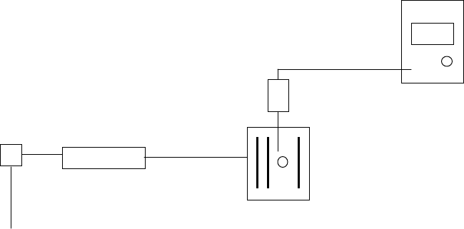
RF Output Power Measurements
Ref: 15.407(a)2
Measurement equipment used:
HP EPM-441A Power meter
HP ECP-E26A power sensor RF power meter
Test set-up: RF sensor
AC/DC IDU ODU
120 VAC Figure 1
Test Procedures
1. Set the IDU to the desired channel and to maximum output power setting
2. RF Output = Meter reading dBm + 30 dB
Test Results: Power Output, Max
Chanel Frequency, MHz Pout, dBm
1 5733.6 12.6
5 5776.6 13.2
8 5807.4 13.2
Wireless Inc. FCC ID: EV9N2-4XE1-5G7
13 of 16
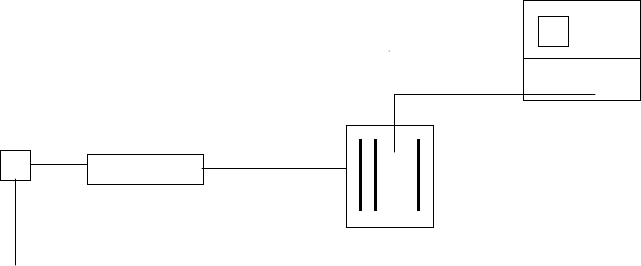
Antenna Conducted Output (For determining bandedge EIRP)
Ref: 15.407(b)2
Measurement equipment used:
HP 8565E spectrum analyzer
30 dB attenuator HP8566
Test set-up:
AC/DC IDU ODU
120 VAC Figure 2
Test Procedures
1. Set EUT to lowest operating channel.
1. Set spectrum analyzer to TX output center frequency, RES BW = 100 kHz,
VID BW = 300 Hz - 3 kHz.
3. Use analyzer MKR funtion to measure output at bandedge and 10 MHz from
bandedge
4. Nomalize to 1 MHz: Reading, dBm + 10log(1MHz/meas BW)
5. Add antenna gain and compare to -17dBm/MHz and /or -27dBm/MHz EIRP
6. Plot spectrum analyzer data
7. Repeat steps 1-6 for highest channel
Test Results
Refer to attached documents bandedgeX.jpg
Worst-case out of band emission:
Channel 1: -43.3 dBm at 5723.08 GHz (-17 dBm EIRP/MHz limit)
Channel 8: -45.5 dBm at 5858.5 GHz (-27 dBm EIRP/MHz limit)
Wireless Inc. FCC ID: EV9N2-4XE1-5G7
14 of 16
Peak Power Spectral Density
Ref: 15.407(b)2
Measurement equipment used:
HP 8565E spectrum analyzer
30 dB attenuator
Test set-up: Refer to Figure 2
Test Procedures
1. Set EUT to lowest operating channel.
2. Set spectrum analyzer to TX output center frequency, RES BW = 1MHz,
VID BW = 1MHz.
3. Using MKR PEAK to find the peak power spectral density
4. Repeat for middle channel and highest channel
Test Results
Measured peak power density is below 13.3 dBm. Refer to attached documents psdX.jpg
Chanel Frequency, MHz PSD dBm/MHz Limit, dBm/MHz
1 5733.6 12.5 17
5 5776.6 13.17 17
8 5807.4 13.17 17
Peak Excursion of Modulation Envelope
Ref: 15.407(a)6
The EUT employs BPSK modulation, which is constant envelope. Measured power is
therefore equivalent to peak power of the envelope. Comparison with PSD data shows
that the difference between peak excursion of the modulation envelope and peak power is
less than 1 dB.
Wireless Inc. FCC ID: EV9N2-4XE1-5G7
15 of 16
Field Strength of Spurious and Harmonic Radiation
Ref: 15.407(c)6
Measurement Equipment Used:
HP 8566 Spectrum Analyzer
HP 11975A Preamplifier, 2 - 8 GHz (used with HP11970 external mixers)
Antenna Research Associates MWH 1826/B, 18 - 26.5 GHz
HP 11970K Harmonic mixer, 18 - 26.5 GHz
HP 11970A Harmonic mixer, 26.5 - 40 GHz
HP 11970Q Harmonic mixer, 33 - 50 GHz
HP 11970V Harmonic mixer, 50 - 75 GHz
HP 11970W Harmonic mixer, 75 - 110 GHz
Low loss antenna cable (0.7 dB/ft @ 24 GHz)
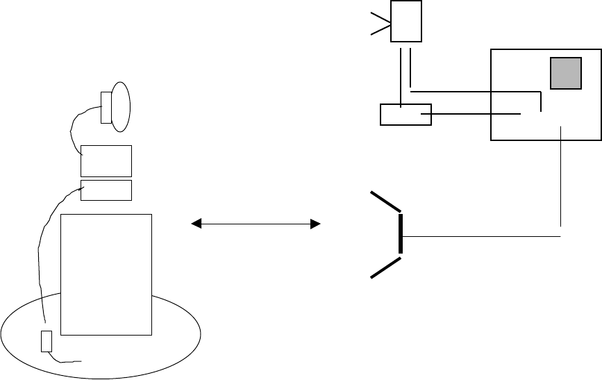
Test Set-Up
external mixer spectrum analyzer
leveling pre-amp
-OR-
30 cm
horn antenna
Wireless Inc. FCC ID: EV9N2-4XE1-5G7
16 of 16
Test Method
With the transmitter operating at full power, the EUT was rotated 360° and the search
antenna was raised and lowered in both polarities, all in an attempt to maximize the
levels of the received emission for each harmonic and spurious emission up to 40 GHz.
Test Results
No emissions above instrumentation noise floor were detected. Tests were performed for
each of the 4 antennas at a LOW, MID, and HIGH channel.
Antenna conducted measurements confirmed there are no harmonic emissions generated
by this transmitter above the noise floor of the spectrum analyzer (-51 dBm or lower).
Using the relationship between field strength, output power and distance
EV/m = (•(30*PW*G))/d meters (E volts/m, P watts, G numeric gain over isotropic)
Assuming G=1, converting volts to microvolts and watts to milliwatts, simplifying and combining
terms, and using a distance of d = 3m
E@3m, dBuV/m = (95.24 + PdBm) dBuV/m = 95.24- 51dBm = 44.24 dBuV/m
!5.205, 15.209 limit: 54 dBuV/m @ 3m