Wireless N2X5-3S1-16B User Manual Dec 17 draft pdf version
Wireless Inc Dec 17 draft pdf version
Wireless >
Contents
Dec 17 draft pdf version

N2-X Ethernet Extender
Installation and Operation Manual
Part Number 281-104101-201
Version 1.0
December 1999
Wireless, Inc.
5452 Betsy Ross Drive
Santa Clara, CA 95054-1101

ii
N2-X Ethernet Extender Installation and Operation Manual
Notice
Information in this document is subject to change without notice. No part of this document may
be reproduced or transmitted in any form or by any means, electronic or mechanical, for any
purpose, without the express written permission of Wireless, Inc.
© Copyright 1999, Wireless, Inc. All rights reserved.
N2-X Ethernet Extender™ and ACCESS™ Series are trademarks of Wireless, Inc.

iii
N2-X Ethernet Extender Installation and Operation Manual
Table of Contents
1.0 General Overview ................................................................................................................. 1
1.1 N2-ACCESS Series Product Family ......................................................................... 1
1.2 Introduction to the N2-X Ethernet Extender .............................................................. 1
1.3 Regulatory Information .............................................................................................. 2
2.0 N2-X Ethernet Extender Product Profile ............................................................................... 3
2.1 General Overview ...................................................................................................... 3
2.2 Specifications ............................................................................................................ 7
2.3 User Interfaces ........................................................................................................ 10
2.4 ODU Performance Monitoring ................................................................................. 15
2.5 Theory of Operation ................................................................................................ 15
3.0 Equipment Installation and Commissioning ........................................................................ 21
3.1 Installation ............................................................................................................... 21
3.2 Ethernet Data Connectors ....................................................................................... 24
3.3 Connect the Power Supply ...................................................................................... 25
3.4 Outdoor RF Unit Installation .................................................................................... 26
3.5 Commissioning ........................................................................................................ 33
4.0 Maintenance and Troubleshooting ...................................................................................... 37
4.1 N2-X Ethernet Extender Maintenance .................................................................... 37
4.2 Identifying and Resolving Receive Signal Strength Issues ..................................... 38
4.3 Dip Switch Function and Configuration ................................................................... 40
4.4 Where to Get Further Assistance ............................................................................ 42
4.5 Return Procedure .................................................................................................... 43
Appendix A Grounding Practices and Lightning Protection Information....................................... A-1
Appendix B Installation Instructions .............................................................................................. B-1
Appendix C Quick Align Antenna Mount Installation .................................................................... C-1
Appendix D Adjustable Panel Antenna Mount ..............................................................................D-1

iv
N2-X Ethernet Extender Installation and Operation Manual

v
N2-X Ethernet Extender Installation and Operation Manual
Figures
Figure 2.1 Typical Deployment of a N2-X Ethernet Extender in a
Point-to-Point Configuration ...................................................................................... 5-6
Figure 2.2a Outdoor Unit, Front View ............................................................................................ 14
Figure 2.2b Outdoor Unit, Back View ............................................................................................ 14
Figure 2.3 N2-X Ethernet Extender Bock Diagram ................................................................ 19-20
Figure 3.1 Power Cord Connection ............................................................................................. 25
Figure 3.2 Outdoor Unit Mounting Hardware .............................................................................. 26
Figure 3.3 Attaching the Pole Mount Adapter Bracket ................................................................ 27
Figure 3.4 Mounting the Outdoor RF Unit to the Bracket ............................................................ 28
Figure 3.5a Mounting Bracket Latch and Stud Mount Detail ......................................................... 29
Figure 3.5b Locking the Mounting Hardware ................................................................................ 30
Figure 3.6a N-Type Antenna and Siamesed Ethernet/Power Connections .................................. 31
Figure 3.6b Ground Connection ....................................................................................................32
Figure 4.1 Frequency Selection for the N2-X Ethernet Extender Radio ..................................... 38
Figure 4.2 Dip Switch Access and Configuration Information ..................................................... 41
Figure B.1 Two Foot Diameter Antenna ..................................................................................... B-1
Figure B.2 Mount Configuration .................................................................................................. B-3
Figure B.3 Mounting Hardware Packed ...................................................................................... B-5
Figure B.4 Mounting Hardware Unpacked .................................................................................. B-5
Figure B.5 Parabolic Reflector .................................................................................................... B-8
Figure B.6 Unpacking the Radome ............................................................................................. B-8
Figure B.7 Antenna Mount Assembly ......................................................................................... B-9
Figure B.8 Antenna Mount Assembly ....................................................................................... B-10
Figure B.9 Elevation Rod Assembly ......................................................................................... B-10
Figure B.10 Feed Horn Installation ............................................................................................. B-11
Figure B.11 Feed Horn Polarization Markings ............................................................................ B-12
Figure B.12 Parabola Rear View Showing Polarization Reference Markers .............................. B-12
Figure B.13 Feed Horn Installation ............................................................................................. B-13
Figure B.14 Feed Horn Installation for Vertical Polarized Operation .......................................... B-13
Figure B.15 Azimuth Clamp/Shear Stop Assembly .................................................................... B-14
Figure B.16 Azimuth Adjustment Clamp Assembly ................................................................... B-14
Figure B.17 Hoisting the Antenna ............................................................................................... B-15
Figure C.1 Quick Align Antenna .................................................................................................. C-1
Figure C.2 Mount Configuration .................................................................................................. C-2
Figure C.3 Azimuth and Elevation Planning ............................................................................... C-4
Figure C.4 Azimuth and Elevation Planning ............................................................................... C-5
Figure D.1 Antenna Mount .......................................................................................................... D-1
Figure D.2 Azimuth and Elevation Planning ............................................................................... D-2

vi
N2-X Ethernet Extender Installation and Operation Manual
Figure D.3 Azimuth and Elevation Planning ............................................................................... D-3
Figure D.4 Flat Panel Antenna ....................................................................................................D-4
Figure D.5 Adjustable Panel Antenna Mount .............................................................................. D-5
Tables
Table 1.1 FCC U-NII Bands ......................................................................................................... 2
Table 2.1 Connector Pin Assignment, 10 Base T Connector on ODU ........................................ 8
Table 2.2 Connector Pin Assignment, Power Supply Input Connector on ODU ......................... 8
Table 2.3 Recommended Antennas ............................................................................................. 9
Table 2.4 Maximum Transmit Power Level Setting vs. Antenna Type (for compliance with
FCC EIRP limits) in the 5.3 GHz Band....................................................................... 11
Table 2.5 Maximum Transmit Power Level Setting vs. Antenna Type (for compliance with
FCC EIRP limits) in the 5.7 GHz Band, Original and July 31, 1998 rules.................. 12
Table 2.6 Configuration Switch .................................................................................................. 13
Table 3.1 Maximum Transmit Power Level Setting vs. Antenna Type (for compliance with
FCC EIRP limits) in the 5.3 GHz Band....................................................................... 22
Table 3.2 Maximum Transmit Power Level Setting vs. Antenna Type (for compliance with
FCC EIRP limits) in the 5.7 GHz Band, Original and July 31, 1998 rules.................. 23
Table 3.3 Inventory of Equipment and Installation Materials ..................................................... 24
Table 3.4 Installation Checklist................................................................................................... 33
Table 3.5 RSSI vs. Receive Signal Level ................................................................................... 34
Table 3.6 Approximation Table .................................................................................................. 35
Table 4.1 Frequencies ................................................................................................................ 39
Table 4.2 Dip Switch Configuration ............................................................................................ 40
Table B.1 Two Foot Diameter Antenna Dimensions ................................................................. B-2
Table B.2a Contents List, Reflector Assembly ............................................................................ B-4
Table B.2b Contents List, Feed Assembly .................................................................................. B-4
Table B.2c Contents List, Mount Assembly ................................................................................. B-6
Table B.2d Contents List, Mount Assembly ................................................................................. B-7
Table B.3 Nut Tightening Procedures ..................................................................................... B-17
Table C.1 Contents List, Quick Align Mount .............................................................................. C-3
Table C.2 Contents List, Reflector Assembly ............................................................................ C-3

vii
N2-X Ethernet Extender Installation and Operation Manual
Welcome!
Welcome to the Wireless, Inc. N2-ACCESS™ Series product family. This manual is designed
to introduce you to the N2-X Ethernet Extender™, and to provide you with information necessary
to plan, install, operate and maintain a N2-X Ethernet Extender wireless communication
system.
The N2-X Ethernet Extender is intended for professional installation only. This manual,
however, is also designed for personnel who plan, operate and administrate the N2-X Ethernet
Extender communication system. Please review the entire manual before powering up or
deploying any N2-X Ethernet Extender.
Updates to this manual will be posted on the Wireless, Inc. Customer Service Website at
http://www.wire-less-inc.com. Registered Wireless customers can access Wireless’ on-line
information and support service, available 24 hours a day, 7 days a week. Our on-line service
provides users with a wealth of up-to-date information, with documents being added or updated
each month.
Radiation Warnings
Microwave Radio Radiation Warning
Under normal operating conditions, N2-X Ethernet Extender radio equipment complies with the
limits for human exposure to radio frequency (RF) fields adopted by the Federal Communica-
tions Commission (FCC). All Wireless, Inc. microwave radio equipment is designed so that
under normal working conditions, microwave radiation directly from the radio is negligible when
compared with the permissible limit of continuous daily exposure recommended in the United
States by ANSI/IEEE C95.1-1991 (R1997), Safety Levels with Respect to Human Exposure to
Radio Frequency Electromagnetic Fields, 3 kHz to 300 GHz.
Microwave signal levels that give rise to hazardous radiation levels can exist within transmitter
power amplifiers, associated RF multiplexers, and antenna systems.
Never look into the open end of a Waveguide as eyes are particularly vulnerable to radiation.
Do not disconnect RF coaxial connectors, open microwave units, or break down any
microwave screening while the radio equipment is operating.

viii
N2-X Ethernet Extender Installation and Operation Manual
Microwave Antenna Radiation Warning
Designed for point-to-point operation, an N2-X Ethernet Extender microwave radio system will
use directional antennas to transmit and receive microwave signals. These directional anten-
nas are usually circular or rectangular in shape, are generally located outdoors, and are usually
mounted on a tower or mast.
Referencing OET Bulletin 65 (Edition 97-01, August 1997) from the Federal Communication
Commission’s Office of Engineering & Technology, limits for maximum permissible exposure
(MPE) to microwave signals have been adopted by the FCC for both Occupational/Controlled
environments and General Population/Uncontrolled environments. These limits are 5.0 mW/
cm2 and 1.0 mW/cm2, respectively, with averaging times of six-minutes and thirty-minutes,
respectively.
The closer you are to the front center-point of a microwave antenna, the greater the power
density of its transmitted microwave signal. Unless you are very close, however, microwave
exposure levels will fall far below the MPE limits. To determine how close to a microwave
antenna you can be and still remain below the MPE limits noted above, “worst case” predictions
of the field strength and power density levels in the vicinity of an N2-X Ethernet Extender™
microwave antenna can be made from the following calculations. The equation is generally
accurate in the far-field of an antenna, and will over-predict power density in the near-field (i.e.
close to the antenna).
S = PG/4πR2
where: S = power density (in mW/cm2)
P = power input to the antenna (mW)
G = power gain of the antenna in the direction of interest relative to an isotropic
radiator
R = distance to the center of radiation of the antenna (cm)
Note that G, the power gain factor, is usually expressed in logarithmic terms (i.e., dB), and must
be converted using the following equation:
G = 10 dB/10
For example, a logarithmic power gain of 24 dB is equal to a numeric gain of 251.19.
Assuming (1) maximum output power from the N2-X Ethernet Extender (+3.5 dBm [2.238 mW]),
(2) no signal loss in the cable connecting the N2-X Ethernet Extender to the antenna, and (3)
the use of a 27 dBi gain parabolic antenna, the 5.0 mW/cm2 and 1.0 mW/cm2 MPE power density
limits would be reached at distances of approximately 4.22 cm and 9.44 cm, respectively.
Wireless, Inc. fully supports the FCC’s adopted MPE limits, and recommends that personnel
maintain appropriate distances from the front of all directional microwave antennas. Should you
have questions about N2-X Ethernet Extender™ microwave signal radiation, please contact the
Wireless, Inc. Customer Service Department.

ix
N2-X Ethernet Extender Installation and Operation Manual
Notice Regarding Operation pursuant to FCC part 15 Rules
This equipment has been tested and found to comply with the limits for a Class A digital device
pursuant to part 15 of the FCC Rules. These limits are designed to provide reasonable
protection against harmful interference when the equipment is operated in a commercial
environment. This equipment generates, uses and can radiate radio frequency energy and, if
not installed and used in accordance with the instruction manual, may cause harmful
interference to radio communications. Operation of this equipment in a residential area is likely
to cause harmful interference in which case the user will be required to correct the interference
at his own expense.

x
N2-X Ethernet Extender Installation and Operation Manual

1
N2-X Ethernet Extender Installation and Operation Manual
1.0 General Overview
1.1 N2-ACCESS Series Product Family
All N2-X Ethernet Extender radios are members of the N2-ACCESS Series radio product family.
The N2-ACCESS Series is designed to provide an economical wireless solution for local access
telecommunication requirements.
This manual addresses, in detail, the operation of the N2-X Ethernet Extender. For detailed
information on other members of the N2-ACCESS Series, please refer to the appropriate
Operation Manual(s).
1.2 Introduction to the N2-X Ethernet Extender
The N2-X Ethernet Extender is a digital radio using spread spectrum modulation techniques
designed for use as a point-to-point communications system. The N2-X Ethernet Extender is
used in the following applications: point-to-point (building to building), ISPs, CLECs, Wireless
Local Loop (WLL), Backup Solutions and Temporary Links.
The N2-X Ethernet Extender radio is designed for operation in two of the Unlicensed National
Infrastructure at frequencies of 5.250 - 5.350 GHz or 5.725 - 5.825 GHz.
Each N2-X Ethernet Extender is comprised of a pole mounted RF/antenna unit. Each link is
powered by means of a DC power supply (optional AC-DC power supply available) which is fed
to the unit through an optional power/data cable. The system has a total data transmission
capacity of 16 Mb/s. Refer to the N2-X Ethernet Extender data sheets for detailed information
relating to product offerings and specifications.

2
N2-X Ethernet Extender Installation and Operation Manual
Table 1.1 - FCC U-NII Bands
1.3 Regulatory Information
In January 1997, the FCC made available 300 MHz of spectrum for Unlicensed National
Information Infrastructure (U-NII) devices. The FCC believes that the creation of the U-NII band
will stimulate the development of new unlicensed digital products which will provide efficient and
less expensive solutions for local access applications.
The U-NII band is divided into three sub bands at 5.15 - 5.25, 5.25 - 5.35 and 5.725 - 5.825 GHz.
The first band is strictly allocated for indoor use and is consistent with the European High
Performance Local Area Network (HIPERLAN). The second and third bands are intended for
high speed digital local access products for “campus” and “short haul” microwave applications.
1dnaB2dnaB3dnaB
ycneuqerF zHG52.5ot51.5zHG53.5ot52.5zHG528.5ot527.5
)xaM(rewoP PRIEsttawillim002PRIEttaw1)PRIE(sttaw4
*
esUdednetnI ylnOesUroodnIsupmaCselim01xorppA
nodesiver)00M(redrodnanoinipomudnaromemCCFtnecerA:etoN* dnaniagiBd32htiwannetnalanoitceridafoesuehtswolla8991,42enuJ IIN-U528.5-527.5ehtnittaw1forewoptuptuorettimsnartmumixama .dnab
109530LW

3
N2-X Ethernet Extender Installation and Operation Manual
2.0 N2-X Ethernet Extender Product Profile
2.1 General Overview
The N2-X Ethernet Extender series of microwave radio products provides digital capacities for
16 Mb/s data rates for short-haul applications up to 10 km. The radio terminal operates in the
Unlicensed National Information Infrastructure (U-NII) spectrum with a revolutionary Split
Modulation system architecture that provides full duplex operation in the 5.3/5.7 GHz U-NII
frequency bands.
The N2-X Ethernet Extender series provides the unique advantage of a very robust digital
transmission scheme.
The product uses two separate 100 MHz bands within the U-NII frequency spectrum. Within
these bands, the N2-X Ethernet Extender series operates in one of many independent channels
providing for frequency reuse and network flexibility, ideal for dense network applications.
Synthesized RF channel selection is field configurable, as are the power output options for the
selection of antenna sizes. Frequency coordination and installation guidelines are provided in
the appendix section of this manual.
Complying with all aspects of FCC Rules Subpart 15.401-15.407, the transmission character-
istics of the N2-X Ethernet Extender series are ideally suited to meet the peak power spectral
density requirements of the U-NII 5.250 - 5.350 and 5.725 - 5.825 GHz bands.
The N2-X Ethernet Extender has been designed for easy access to all interfaces, controls, and
displays. Information in this manual will familiarize you with all of these items. Figure 2.1
illustrates two (2) N2-X Ethernet Extender terminals in a point-to-point configuration.

4
N2-X Ethernet Extender Installation and Operation Manual
This Page Left Blank Intentionally

5
N2-X Ethernet Extender Installation and Operation Manual
Figure 2.1 Z-fold (WL035902) goes here

6
N2-X Ethernet Extender Installation and Operation Manual
Figure 2.1 Z-fold (WL035902) goes here

7
N2-X Ethernet Extender Installation and Operation Manual
2.2 Specifications
2.2.1 General Specifications
Frequency Range: 5.250 - 5.350 GHz and 5.725 - 5.825 GHz
RF Channel Bandwidth: 12 MHz
Channel Increments: 10.24 MHz
Radio Operation: Full duplex
Antenna Port Impedance: 50 Ω nominal
Antenna Port Return Loss: ≥ 10 dB
Ethernet Data Rate: 16 Mbps full duplex, 8 Mbps half duplex
2.2.2 Transmitter Specifications
Frequency Range: 5.250 - 5.350 GHz and 5.725 - 5.825 GHz
Channel Increments: 10.24 MHz
Modulation: BPSK
Power Output: 0, +4, +8, and +12 dBm Avg.
Transmit Duty Cycle: 100%
Emission Mask: Per FCC 15.407
Frequency Stability: ± 5 ppm
Spurious and Harmonic Output: ≤-60 dBc
Data Rate: 8 Mbps
2.2.3 Receiver Specifications
Type: Coherent Detection
Sensitivity: ≤ -84 dBm @ 1x10⁻⁶ BER = 1x10⁻² Packet Error Rate
Maximum RF Input: -20 dBm
Data Rate: 8 Mbps
Channel Increments: 10.24 MHz
Frequency Stability: ± 5 ppm
Receiver Saturation: ≥ -20 dBm
1st Image Rejection: ≥ 60 dB
Other Spurious Rejection: ≥ 50 dB
*Tolerance of Interferers (on adjacent channels):
Channels N-1, N+1 +30 dBc
Channels N-2, N+2 +50 dBc
Channels N-3, N+3 +70 dBc
*Note: Measured at 10 to 40 dB above threshold with similar radio as interferer. Ratio of power
from same power boresight remotes in adjoining 60 degree sectors with 1:8 range differential
is -25 dB for the standard Gabriel 2 foot dish.
1st Image Rejection: ≥ 60 dB
Other Spurious Rejection: ≥ 50 dB

8
N2-X Ethernet Extender Installation and Operation Manual
2.2.5 Power Supply Input Connector on ODU
The 4-pin CircularMil power supply input connector pin assignments are shown in Table 2.2.
Note: The white lead of the power side of the optional Data/Power cable connects to Pin 1,
thus it should be connected to the negative lead of the power source. The red lead of the
power side of the optional Data/Power cable connects to Pin 2, thus it should be connected
to the positive lead of the power source.
2.2.4 Digital Interface
Ethernet Interference on ODU
The 8-pin CircularMil (10Base-T Ethernet interface/ODU status signals) connector pin assign-
ments are shown in Table 2.1. Note that the functions of pins 4, 5 ,7, and 8 are non-standard,
are presently used for proprietary purposes only and should be disabled by switching position
7 of the 10 position switch to the “On” position.
niPDAELnoitcnuF
1+XT+timsnarTriaPdetsiwT
2-XT-timsnarTriaPdetsiwT
3+XR+evieceRriaPdetsiwT
4mralAlacoL/rwPUDInoDEL"mralAlacoL/rewoP"sevirdtahtlangiS
5kniLFRUDInoDEL"kniLFR"sevirdtahtlangiS
6-XR-evieceRriaPdetsiwT
7LILPTUDInoDEL"ytirgetnItenrehtE"sevirdtahtlangiS
8.dnGdnuorG
309691LW
Table 2.1 - Connector Pin Assignment, 10 Base T Connector on ODU
Table 2.2 - Connector Pin Assignment, Power Supply Input Connector on ODU
niPdaeLnoitcnuF
1)-(tupnIevitageN.ylppusrewopfodaelevitagenotnoitcennoC
2)+(tupnIevitisoP.ylppusrewopfodaelevitisopotnoitcennoC
3desUtoN
4desUtoN
109492LW

9
N2-X Ethernet Extender Installation and Operation Manual
epyTrebmuNtraPdnarerutcafunaM
iBd1.82,dezireloPenalP,hsidretemaid'2IRA25-2PSSleirbaG
iBd1.82,dezireloPlauD,hsidretemaid'2IRA25-2DSSleirbaG
iBd5.33,dezireloPenalP,hsidretemaid'4*A25-4PSSleirbaG
iBd5.33,dezireloPlauD,hsidretemaid'4*A25-4DSSleirbaG
iBd5.71,dezireloPenalP,lenaPtalF"625-5.SPFDleirbaG
iBd32,dezireloPenalP,lenaPtalF"2125-1SPFDleirbaG
iBd5.72,dezireloPenalP,lenaPtalF"4225-2SPFDleirbaG
.tnailpmocCCFtoN*
209691LW
Table 2.3 - Recommended Antennas
2.2.6 Antennas
The antennas shown in Table 2.3 are recommended for use with N2-X. With the exception of
the 4’ dishes, all antennas have been tested with N2-X to verify compliance with applicable FCC
rules. Data sheets for antennas can be found in Appendix B.
2.2.7 Power Requirements
Primary power supply
DC ±20 to ±56 V
AC 100 to 240V 50/60 Hz with optional external power supply.
Power Consumption Maximum 17 Watts
2.2.8 Environmental Specifications
Outdoor Unit Operating Temperature Range: -30°C to +60°C
Storage Temperature Range: -40°C to +85°C
Altitude: 4,500 meters max.
Humidity: Outdoor, all-weather enclosure
2.2.9 Mechanical
Dimensions
ODU 310mm x 351mm x 73mm (HxWxD)
Weight
ODU 5 kg

10
N2-X Ethernet Extender Installation and Operation Manual
2.3 User Interfaces
The N2-X Ethernet Extender provides user interfaces for fused DC power connection, electrical
grounding, radio frequency (RF) antenna connection, Ethernet connection, configuration and
RSSI output. The following provides information on each interface.
Outdoor Unit
•Data/Power Cable - Siamesed CAT-5 Ethernet and power cables.
•RSSI - BNC type connector used for RSSI measurement.
•Antenna (RF) Connector - N-type female connector used for connection with antenna.
•Main Power - The N2-X Ethernet Extender is designed to work from a power input of 20
to 56 VDC.
•Grounding Connector - The front panel of the N2-X Ethernet Extender is equipped with
an M5 ground screw and associated washers. This ground screw serves as the proper
chassis-ground connection point for an external ground source. The N2-X Ethernet
Extender must be grounded in accordance with the electrical codes, standards, and
practices governing the local installation.
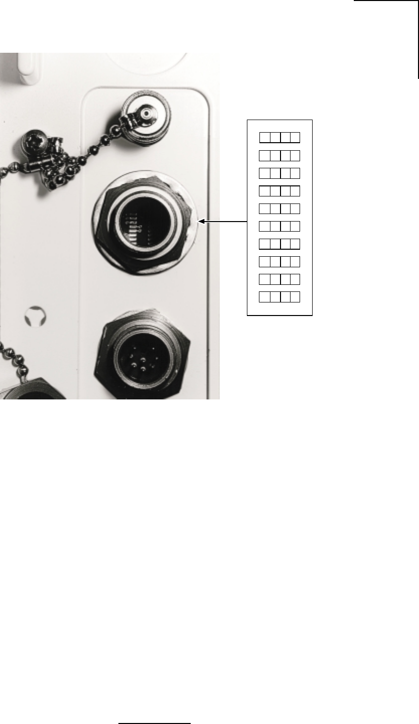
•Configuration Switch - Configuration of the N2-X Ethernet Extender is performed via a
DIP switch on the ODU. The 10-position DIP switch is accessible by removing the water-
tight dust cap on the ODU. Once exposed, each of the 10 switches can be manipulated
using a fine point instrument such as a small-tipped screwdriver. The function of each
switch is explained in Table 2.6. Note: Primary power must be cycled off, then on, for
changes in DIP switch settings to take affect.

11
N2-X Ethernet Extender Installation and Operation Manual
epyTannetnAN/PrerutcafunaM timsnarTmumixaM )mBd(gnitteSrewoP
iBd1.82,deziraloPenalP,emodarhtiwhsidretemaid'2 IRA25-2PSSleirbaG0
iBd1.82,deziraloPlauD,emodarhtiwhsidretemaid'2 IRA25-2DSSleirbaG0
iBd5.71,deziraloPenalP,lenaPtalF"6 25-5.DPFDleirbaG21+
iBd32,deziraloPenalP,lenaPtalF"21 25-1DPFDleirbaG4+
iBd5.72,deziraloPenalP,lenaPtalF"42 25-2DPFDleirbaG0
129102LW
Per Table 2.4, in the 5.3 GHz band the highest power setting (approximately +12 dBm) can only
be installed with the lowest gain antenna which is the 6” Flat Panel Plane Polarized (DFPD.5-
52) with 17.5 dBi. Each radio is shipped from the factory with a standard 6’ coaxial cable for
connection between the radio and the antenna. The cable has a nominal loss of approximately
2.6 dB.
UNII radios are covered under CFR 47 FCC part 15, 15.407 Subpart E. 15.407.a.2 which states
Ptransmit = 11 dBm + 10 log B where B is the -26 dB BW with a 6 dBi antenna. Above 6 dBi
antenna gain there is a 1:1 reduction in Ptransmit to maintain the same Maximum EIRP. This
is accomplished by the changes in output power setting for the alternative antennas.
The FCC EIRP limit for the 5.3 GHz band with our transmitter bandwidth is +28 dBm. With the
transmit power set to +12 dBm, the EIRP with the 6” Flat Panel antenna, and standard 6’ coaxial
cable will be:
12 dBm + 17.5 dBi - 2.6 dB = 26.9 dBm
Table 2.4 - Maximum Transmit Power Level Setting vs. Antenna Type (for compliance with FCC EIRP
limits) in the 5.3 GHz Band
12
N2-X Ethernet Extender Installation and Operation Manual
Per Table 2.5, in the 5.7 GHz band the highest power setting (approximately +12 dBm) can only
be installed with the lowest gain antenna which is the 6” Flat Panel Plane Polarized (DFPD.5-
52) with 17.5 dBi. Each radio is shipped from the factory with a standard 6’ coaxial cable for
connection between the radio and the antenna. The cable has a nominal loss of approximately
2.6 dB.
UNII radios are covered under CFR 47 FCC part 15, 15.407 Subpart E. 15.407.a.3 which states
Ptransmit = 17 dBm + 10 log B where B is the -26 dB BW with a 6 dBi antenna. Above 6 dBi
antenna gain there is a 1:1 reduction in Ptransmit to maintain the same Maximum EIRP. This
is accomplished by the changes in output power setting for the alternative antennas.
The original FCC EIRP limit for the 5.7 GHz band with our transmitter bandwidth is +33 dBm.
With the transmit power set to +12 dBm, the EIRP with the 6” Flat Panel antenna, and standard
6’ coaxial cable will be:
12 dBm + 17.5 dBi - 2.6 dB = 26.9 dBm
The corresponding settings are included in Table 2.5.
Table 2.5 - Maximum Transmit Power Level Setting vs. Antenna Type (for compliance with FCC EIRP
limits) in the 5.7 GHz Band, Original and July 31, 1998 rules
epyTannetnAN/PrerutcafunaM timsnarTmumixaM )mBd(gnitteSrewoP
iBd1.82,deziraloPenalP,emodarhtiwhsidretemaid'2 IRA25-2PSSleirbaG0
iBd1.82,deziraloPlauD,emodarhtiwhsidretemaid'2 IRA25-2DSSleirbaG0
iBd5.71,deziraloPenalP,lenaPtalF"6 25-5.DPFDleirbaG21+
iBd32,deziraloPenalP,lenaPtalF"21 25-1DPFDleirbaG8+
iBd5.72,deziraloPenalP,lenaPtalF"42 25-2DPFDleirbaG4+
229102LW
The FCC will also allow higher EIRP for point to point links with higher gain antennas. Page 703
of the FCC document, CFR 47 FCC part 15, 15.407 Subpart E, FR 40836, July 31, 1998 has
the provisions for these power limits. The path length is not increased, since the 5.3 GHz
transmitter is not allowed the higher EIRP. We recommend the higher power settings only
when absolutely necessary.
This rule states “fixed pt-pt U-NII devices operating in this band may employ transmitting
antennas with directional gain up to 23 dBi without the corresponding reduction in transmitter
peak output power or peak power spectral density.” Also above 23 dBi antenna gain there is a
1:1 reduction in Pout to maintain the same Max EIRP.
We are in compliance even at the maximum antenna gain and transmitter power, since the
corresponding output power is over +27 dBm in our BW and the resulting EIRP for a 6 dBi
antenna is +33 dBm. This EIRP limit is further extended to +44 dBm by a +23 dBi antenna. Our
EIRP with a 23 dBi antenna at maximum output power is 12 dBm + 23 dBi - 2.6 dB = +32.4 dBm.
With the highest gain antenna and maximum output power the EIRP would be 12 dBm + 28.1
dBi - 2.6 dB = +37.5 dBm.
13
N2-X Ethernet Extender Installation and Operation Manual
Table 2.6 - Configuration Switch
hctiwSnoitcnuF
3dna,2,1
noitceleSlennahCdnaycneuqerF
1hctiwS2hctiwS3hctiwS.hC)zHG(riaPycneuqerF
ffOffOffO1 08062.586537.5
ffOffOnO2 40172.529547.5
ffOnOffO3 82182.561657.5
ffOnOnO4 25192.504667.5
nOffOffO5 67103.546677.5
nOffOnO6 00213.588687.5
nOnOffO7 42223.521797.5
nOnOnO8 84233.563708.5
5dna4
lortnoCrewoPtimsnarT
4hctiwS5hctiwSzHG7.5/zHG3.5troPannetnAtarewoPxT
ffOffOmBd21+
ffOnOmBd8+
nOffOmBd4+
nOnOmBd0+
6edoMtenrehtE
xelpuDflaH=ffO xelpuDlluF=nO
7
elbasiDUDI UDIotdetcennoceblliwUDO=ffO lliwUDO=nOton UDIotdetcennoceb
:etoN siti,tnempiuqelanretxeotegamadlaitnetoptneverpotredronI ehtotteseb7hctiwstahtevitarepmi nO .noitisop
8gniretliFtekcaP delbanegniretliFtekcaP=ffO delbasidgniretliFtekcaP=nO
01dna9desutoN
:etoN ninwohserasgnitteshctiwsPIDtluafedyrotcaF dlob .ecafepyt
109791LW

14
N2-X Ethernet Extender Installation and Operation Manual
Figure 2.2a - Outdoor Unit, Front View
Figure 2.2b - Outdoor Unit, Back View
WL201906
Dip Switch
Access
Siamesed Category 5
Ethernet and
Power cables connections
Antenna Connection
(N Type, Female)
ODU
Ground Connection
Mounting
Studs
WL201901
Receive Signal Strength
Indicator (RSSI) (BNC Type,
Female)

15
N2-X Ethernet Extender Installation and Operation Manual
2.4 ODU Performance Monitoring
RSSI - A voltage provided through a BNC connector on the outside of the ODU. The RSSI port
is used for antenna alignment during installation and for periodic measurement of Receiver/
Path performance. The RSSI voltage in proportion to the receive signal level ranges from -30
dBm to -90 dBm.
2.5 Theory of Operation
General Overview
The N2-X is a point to point Wireless Ethernet Extension operating in the 5.3/5.7 GHz UNII band
as authorized in rule sections 15.401 through 15.407. The unit is enclosed in a weather proof
outdoor enclosure and is intended to provide data links over distances up to 10 km. The radio
in the unit operates full duplex, transmitting and receiving data at the rate of 8.192 Mbps. The
radio is modulated using BPSK.
Circuit Description
The following circuit description is intended to explain the operation of the radio at the block
diagram level. This text is written with the idea that the reader has the block diagram readily
available, as it will aid in understanding the signal flow in the radio.
2.5.1 N2-X Ethernet Extender Transmitter
The input to the radio consists of 10 Mbps Ethernet packets that are routed to the Ethernet
bridge chip. The bridge chip stores the data packets, and then converts them into a synchronous
8.192 Mbps data stream that is fed into the transmitter.
The data is differentially encoded and scrambled before it is routed through the transmit
baseband filter to provide spectral shaping. The baseband filter is a five pole low pass filter. After
amplification, the baseband signal is fed to the modulator consisting of a doubly balanced mixer.
The modulator is running directly at the transmitter frequency of 5.775 GHz ± 50 MHz. The local
oscillator signal of the mixer is supplied from the frequency synthesizer section, with the
frequency dependant on the RF channel selected. Operation of the frequency synthesizer will
be detailed later in this document.
From the output of the modulator, the signal is amplified and then passed through a 150 MHz
wide bandpass filter to remove any local oscillator products from the output spectrum. After
filtering, the signal is passed through a series of amplifier and attenuator stages that are used
to control the output power level. With a combination of fixed and variable attenuation the output
power can be set to one of four different levels to accommodate different antennas used with
the product.
The power setting is maintained by an active ALC circuit that samples the transmitter output
power and then adjusts the variable attenuator to keep the output power constant over the
operating temperature of the unit. The power level is controlled to within +1/-2 dB of the set point.
Following the attenuators the signal is fed through additional amplification to bring the output
level to a maximum of +14 dBm at the output of power amplifier. A lowpass matching section
follows the power amplifier to aid in filtering harmonics of the signal. After passing through the
duplexer, the power level at the antenna port is a maximum of +12 dBm.

16
N2-X Ethernet Extender Installation and Operation Manual
2.5.2 N2-X Ethernet Extender Receiver
The receiver in the N2-X is a conventional dual conversion design with IF frequencies of 474.88
MHz and 70 MHz.
From the receive port of the duplexer, the low level input signal is passed through a low noise
preamplifier that provides 25 dB of gain. Following the preamplifier the signal is passed through
a 200 MHz wide bandpass filter to provide image rejection for the first mixer.
The signal is then mixed with the first LO to convert the signal to 474.88 MHz. Following further
amplification the signal is passed through a five pole, 20 MHz wide bandpass filter. This filter
provides image filtering for the second mixer, and also helps attenuate signals on the adjacent
receive channels. After filtering, the signal is further amplified and then passed through a
variable attenuator stage before it is applied to the second mixer.
The output of the second mixer is at 70 MHz. The 70 MHz IF stages provide additional gain along
with two sections of variable attenuation for the AGC function. The primary adjacent channel
filtering is also at 70 MHz where the signal is passed through a 12 MHz wide SAW filter. The
combination of filters provide a minimum of 47 dB of attenuation at the adjacent receive
channels (±10.24 MHz).
At the end of the 70 MHz IF chain the signal is fed into a quadrature demodulator. The carrier
recovery loop consists of a four quadrant multiplier that multiplies I and Q baseband signals to
create an error voltage. This error voltage is then amplified and fed back to the 70 MHz VCO.
This forms a phase locked loop that is locked to the received carrier frequency.
The 70 MHz output is also fed into a wide band logarithmic amplifier that provides a DC voltage
output proportional to the 70 MHz signal strength. The DC voltage is then integrated and fed
back to the variable attenuator stages to form an AGC control loop. This control loop keeps the
signal level at the input to the demodulator chip constant over the entire operating range of the
receiver.
Data recovery from the I baseband signal begins by passing the I signal through a slicer. The
output of the slicer is a digital signal that contains both data and clocking information. A clock
recovery circuit recovers receive timing information that is needed to clock the data through the
descrambler, and differential decoder.
The recovered data stream is then formatted into Ethernet packets and sent out the 10 base-
T Ethernet connector.

17
N2-X Ethernet Extender Installation and Operation Manual
2.5.3 Synthesizer
The FPGA provides four 22-bit streams in a serial format loaded to the synthesizer. This data
provides all of the possible frequencies at which the system can operate. Depending upon the
dip switch settings selected, the actual frequency being used is selected. When the reset button
is pressed, the FPGA will reload this data to the synthesizer.
Frequency Synthesis
The local oscillator frequencies used in the N2-X are all synthesized from a 19.2 MHz, ± 2.5
PPM reference oscillator. The overall frequency stability of the radio is ± 2.5 PPM, directly
reflecting the reference oscillator stability.
A dual frequency synthesizer chip is used to control both the first and second local oscillator
loops. This chip supports one high frequency oscillator, up to 1.5 GHz, and one lower frequency
oscillator to be used as a second LO.
The first local oscillator VCO operates at one half the transmitter output frequency, and changes
with the transmit channel selected. The first LO consists of a bipolar VCO operating at 2.887
GHz ±25 MHz. The output of this VCO is buffered and then passed through a X2 prescaler chip
before being fed back to the synthesizer chip. The phase comparison frequency for the first LO
is 320 kHz.
After amplification the 2.887 GHz signal is passed through a frequency doubler to create the
5.775 GHz signal that is applied to the mixer stages.
The second local oscillator consists of a VCO that is phase locked to 404.88 MHz. This auxiliary
synthesizer is operating with a phase comparison frequency of 240 kHz.

18
N2-X Ethernet Extender Installation and Operation Manual
This page left blank intentionally

19
N2-X Ethernet Extender Installation and Operation Manual
Figure 2-3 Block Diagram (WL196901) goes here

20
N2-X Ethernet Extender Installation and Operation Manual
Figure 2-3 Block Diagram (WL196901) goes here

21
N2-X Ethernet Extender Installation and Operation Manual
3.0 Equipment Installation and Commissioning
3.1 Installation
The N2-X Ethernet Extender has been specifically designed for ease of installation. The
following installation instructions should be followed.
1. Plan the installation - Decide where each component of the N2-X Ethernet Extender will
be placed prior to commencement of any installation activity. Installation considerations for
each component in general are as follows:
a. Outdoor RF Unit - Mount as close as practical to the Antenna assembly. The maximum
distance is determined by the included interconnect cable which is 2 meters maximum
in length. Determine pole mounting details for the Outdoor Unit and Antenna.
Table 3.1 identifies the maximum transmit power level setting that can be used with each
antenna while maintaining compliance with FCC EIRP regulations. Power levels are
referenced to the antenna port of the radio and are average power levels indicating what
would be measured using an average power meter. The FCC expresses limits as peak
power numbers. To convert from the average power numbers to peak power numbers,
add 1.8 dB to the average power numbers.
If the product is being deployed in a country not governed by FCC regulations, the
installer should select a transmit power level setting appropriate for the antenna that is
deployed to maintain compliance with regulations employed by that country.
Refer to Table 2.6 for Configuration Switch setting information.
b. Antenna Unit - See Appendix B.
22
N2-X Ethernet Extender Installation and Operation Manual
epyTannetnAN/PrerutcafunaM timsnarTmumixaM )mBd(gnitteSrewoP
iBd1.82,deziraloPenalP,emodarhtiwhsidretemaid'2 IRA25-2PSSleirbaG0
iBd1.82,deziraloPlauD,emodarhtiwhsidretemaid'2 IRA25-2DSSleirbaG0
iBd5.71,deziraloPenalP,lenaPtalF"6 25-5.DPFDleirbaG21+
iBd32,deziraloPenalP,lenaPtalF"21 25-1DPFDleirbaG4+
iBd5.72,deziraloPenalP,lenaPtalF"42 25-2DPFDleirbaG0
129102LW
Table 3.1 - Maximum Transmit Power Level Setting vs. Antenna Type (for compliance with FCC EIRP
limits) in the 5.3 GHz Band
Per Table 3.1, in the 5.3 GHz band the highest power setting (approximately +12 dBm) can only
be installed with the lowest gain antenna which is the 6” Flat Panel Polarized (DFPD.5-52) with
17.5 dBi. Each radio is shipped from the factory with a standard 6’ coaxial cable for connection
between the radio and the antenna. The cable has a nominal loss of approximately 2.6 dB.
UNII radios are covered under CFR 47 FCC part 15, 15.407 Subpart E 15.407.a.2 which states
Ptransmit = 11 dBm + 10 log B where B is the -26 dB BW with a 6 dBi antenna. Above 6 dBi
antenna gain there is a 1:1 reduction in Ptransmit to maintain the same Maximum EIRP. This
is accomplished by the changes in output power setting for the alternative antennas.
The FCC EIRP limit for the 5.3 GHz band with our transmitter bandwidth is +28 dBm. With the
transmit power set to +12 dBm, the EIRP with the 6” Flat Panel antenna, and standard 6’ coaxial
cable will be:
12 dBm + 17.5 dBi - 2.6 dB = 26.9 dBm
23
N2-X Ethernet Extender Installation and Operation Manual
Per Table 3.2, in the 5.7 GHz band the highest power setting (approximately +12 dBm) can only
be installed with the lowest gain antenna which is the 6” Flat Panel Polarized (DFPD.5-52) with
17.5 dBi. Each radio is shipped from the factory with a standard 6’ coaxial cable for connection
between the radio and the antenna. The cable has a nominal loss of approximately 2.6 dB.
UNII radios are covered under CFR 47 FCC part 15, 15.407 Subpart E 15.407.a.3 which states
Ptransmit = 17 dBm + 10 log B where B is the -26 dB BW with a 6 dBi antenna. Above 6 dBi
antenna gain there is a 1:1 reduction in Ptransmit to maintain the same Maximum EIRP. This
is accomplished by the changes in output power setting for the alternative antennas.
The original FCC EIRP limit for the 5.7 GHz band with our transmitter bandwidth is +33 dBm.
With the transmit power set to +12 dBm, the EIRP with the 6” Flat Panel antenna, and standard
6’ coaxial cable will be:
12 dBm + 17.5 dBi - 2.6 dB = 26.9 dBm
The corresponding settings are included in Table 3.2.
epyTannetnAN/PrerutcafunaM timsnarTmumixaM )mBd(gnitteSrewoP
iBd1.82,deziraloPenalP,emodarhtiwhsidretemaid'2 IRA25-2PSSleirbaG0
iBd1.82,deziraloPlauD,emodarhtiwhsidretemaid'2 IRA25-2DSSleirbaG0
iBd5.71,deziraloPenalP,lenaPtalF"6 25-5.DPFDleirbaG21+
iBd32,deziraloPenalP,lenaPtalF"21 25-1DPFDleirbaG8+
iBd5.72,deziraloPenalP,lenaPtalF"42 25-2DPFDleirbaG4+
229102LW
Table 3.2 - Maximum Transmit Power Level Setting vs. Antenna Type (for compliance with FCC EIRP
limits) in the 5.7 GHz Band, Orignial and July 31, 1998 rules
The FCC will also allow higher EIRP for point to point links with higher gain antennas. Page 703
of the FCC document, CFR 47 FCC part 15, 15.407 Subpart E, FR 40836, July 31, 1998 has
the provisions for these power limits. The path length is not increased, since the 5.3 GHz
transmitter is not allowed the higher EIRP. We recommend the higher power settings only
when absolutely necessary.
This rule states “fixed pt-pt U-NII devices operating in this band may employ transmitting
antennas with directional gain up to 23 dBi without the corresponding reduction in transmitter
peak output power or peak power spectral density”. Also above 23 dBi antenna gain there is a
1:1 reduction in Pout to maintain the same Max EIRP.
We are in compliance even at the maximum antenna gain and transmitter power, since the
corresponding output power is over +27 dBm in our BW and the resulting EIRP for a 6 dBi
antenna is +33 dBm. This EIRP limit is further extended to +44 dBm by a +23 dBi antenna. Our
EIRP with a 23 dBi antenna at maximum output power is 12 dBm + 23 dBi - 2.6 dB = +32.4 dBm.
With the highest gain antenna and maximum output power the EIRP would be 12 dBm + 28.1
dBi - 2.6 dB = +37.5 dBm.

24
N2-X Ethernet Extender Installation and Operation Manual
2. Inventory your equipment and installation materials.
To install one (1) terminal you should have the items shown in Table 3.3.
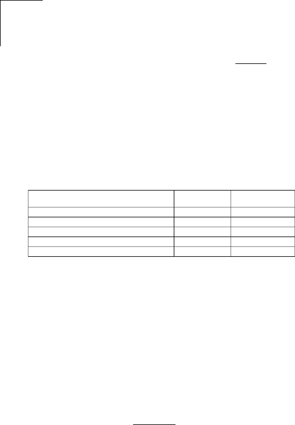
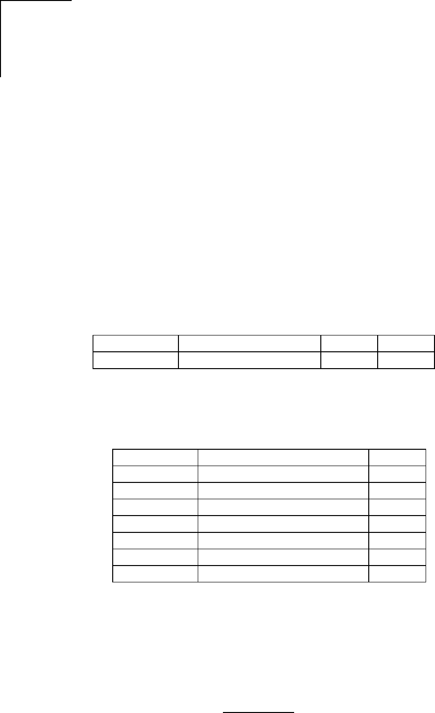
3. The following tools should be on hand:
Tool Purpose
Wire Stripper/Cutter General wire stripping and cutting purposes
Hand-Held Voltmeter (DMM) Confirm magnitude, polarity, continuity
with standard probes
2 Adjustable Wrenches Antenna mounting, Outdoor Unit up to 1.5 cm
#2 Phillips Screwdriver Outdoor Unit Grounding
Table 3.3 - Inventory of Equipment and Installation Materials
ytQnoitpircseD
1rednetxEtenrehtEX-2N
1srenetsafdetaicossadnatekcarBdetnuoMllaWroeloP
1elbaCrewoP/tenrehtEdesemaiS
1ylbmessAelbaClaixaoCelaM-NotelaM-N
659530LW
3.2 Ethernet Data Connectors
The Ethernet connections are made to the data side of the power/data cable assembly, normally
it is supplied with an RJ45 connector.
25
N2-X Ethernet Extender Installation and Operation Manual
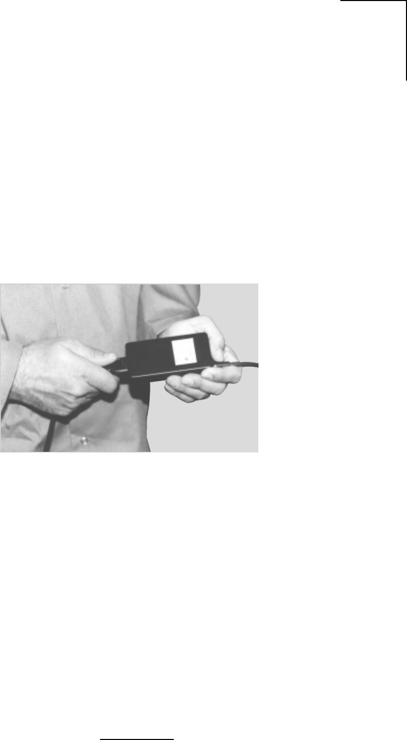
Figure 3.1- Power Cord Connection
WL035907
3.3 Connect the Power Supply
3.3.1 DC Power Supply
The white lead of the power side of the optional Data/Power cable connects to Pin 1, thus it
should be connected to the negative lead of the power source. The red lead of the power side
of the optional Data/Power cable connects to Pin 2, thus it should be connected to the positive
lead of the power source.
3.3.2 Optional AC Power Supply
The AC-DC power supply is connected to an AC outlet by means of an IEC type power cord.
Connect the power cord to the supply as shown in Figure 3.1. The output of the supply should
be connected to the power side of the optional Data/Power cable using guidelines shown in
Table 2.2.
26
N2-X Ethernet Extender Installation and Operation Manual
3.4 Outdoor RF Unit Installation
General
The outdoor unit is installed by means of a pole mount adaptor bracket (wall mount optional)
that is secured to the pole using two metal hose type clamps. Figure 3.2 shows the hardware
provided to mount the Outdoor RF Unit.
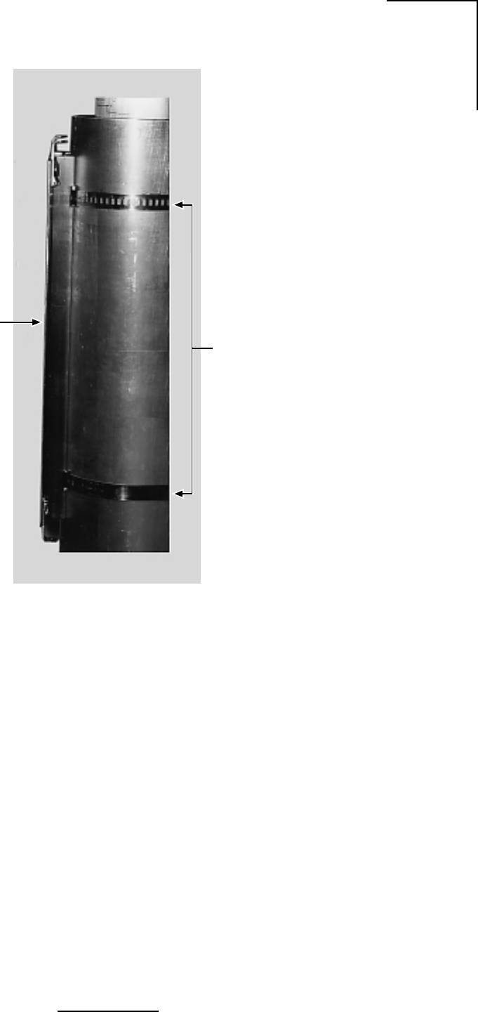
1. Install the outdoor unit pole mount adaptor bracket using the supplied metal hose type
clamps. See Figure 3.3.
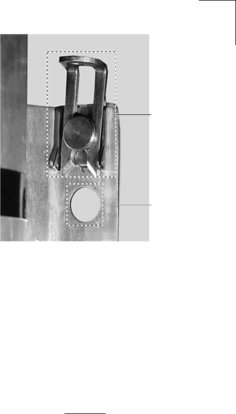
2. Align the four mounting studs on the outdoor unit with the bracket holes (See Figure 3.4)
and secure to the bracket by pushing down the latches as shown in Figures 3.5a and 3.5b.
3. Connect the Siamesed Category 5 Ethernet/power cable, the N-type antenna and the
ground connections as shown in Figures 3.6a and 3.6b.
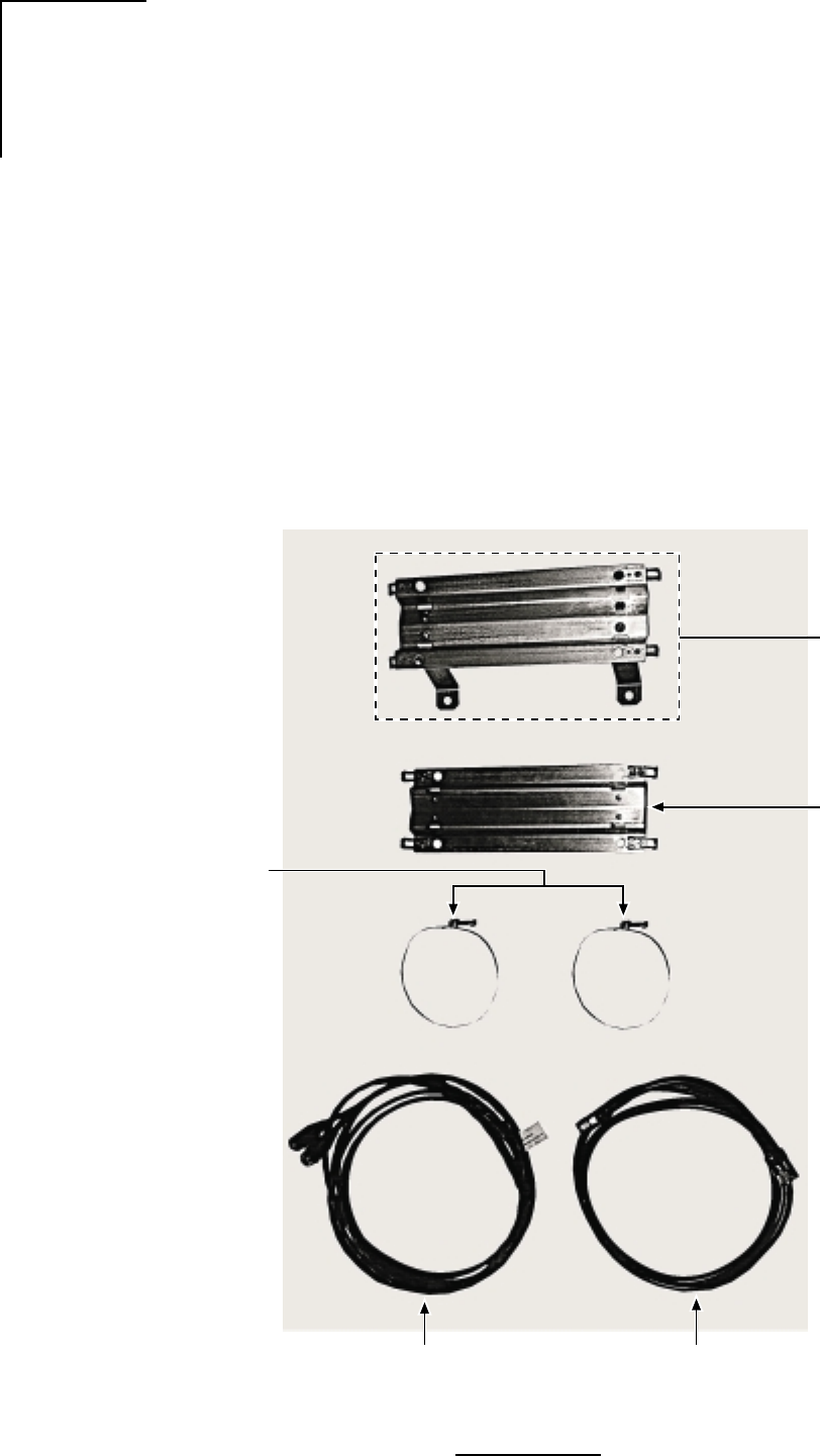
Figure 3.2 - Outdoor Unit Mounting Hardware
Siamesed Catagory 5
Ethernet and Power Cable
for ODU Interconnection
N-Male to N-Male
ODU to Antenna
Coaxial Cable Assembly
Pole Mount
Bracket Fasteners
Wall Mount Bracket
(Optional)
Pole Mount Bracket
WL201909
27
N2-X Ethernet Extender Installation and Operation Manual
Figure 3.3 - Attaching the Pole Mount Adaptor Bracket
Pole Mount
Bracket Hose
Clamps
WL201910

28
N2-X Ethernet Extender Installation and Operation Manual
Figure 3.4 - Mounting the Outdoor RF Unit to the Bracket
Pole Mount
Bracket
Outdoor Unit
WL201907
29
N2-X Ethernet Extender Installation and Operation Manual
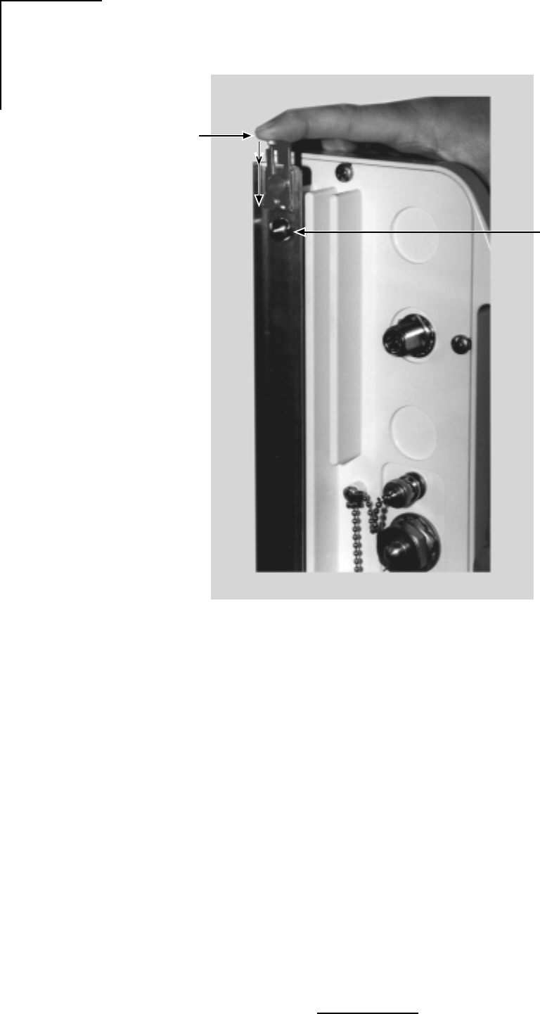
Figure 3.5a - Mounting Bracket Latch and Stud Mount Detail
Detail of Latch Mechanism
for Securing the Outdoor Unit
to the Pole Mount
(4 Places on Bracket)
Outdoor Unit
Mounting Studs
placed through
this hole
WL201905
30
N2-X Ethernet Extender Installation and Operation Manual
Figure 3.5b - Locking the Mounting Hardware
Mounting
Studs x 4
Press locking latches
down to secure the ODU
to the pole mount bracket
WL201903
31
N2-X Ethernet Extender Installation and Operation Manual
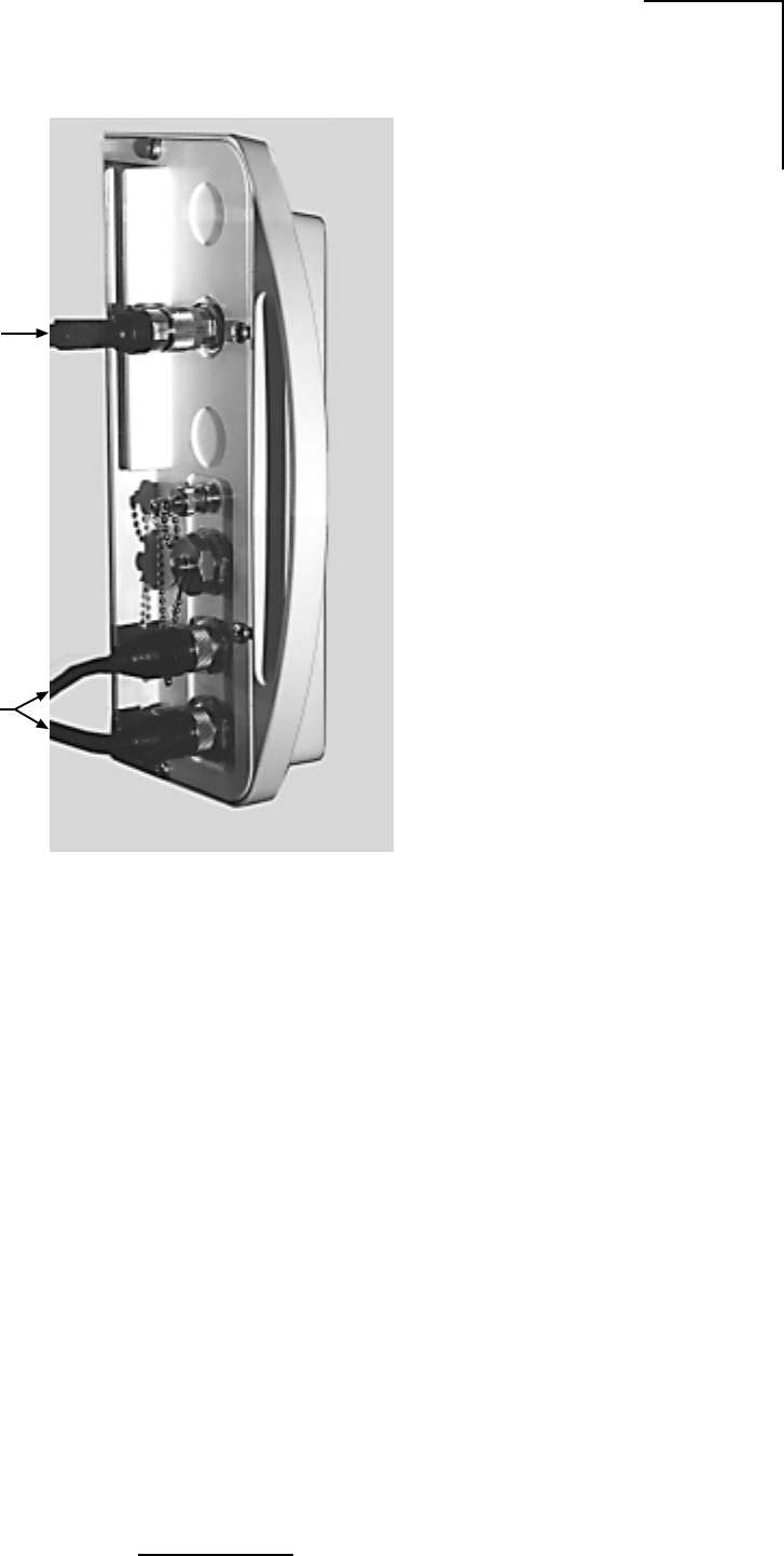
Figure 3.6a - N-Type Antenna and Siamesed Ethernet/Power Connections
WL201904
N-Type
Antenna
Connector
Siamesed Category 5
Ethernet / Power Cable

32
N2-X Ethernet Extender Installation and Operation Manual
Figure 3.6b - Ground Connection
Ground Cable
(not supplied)
WL201902

33
N2-X Ethernet Extender Installation and Operation Manual
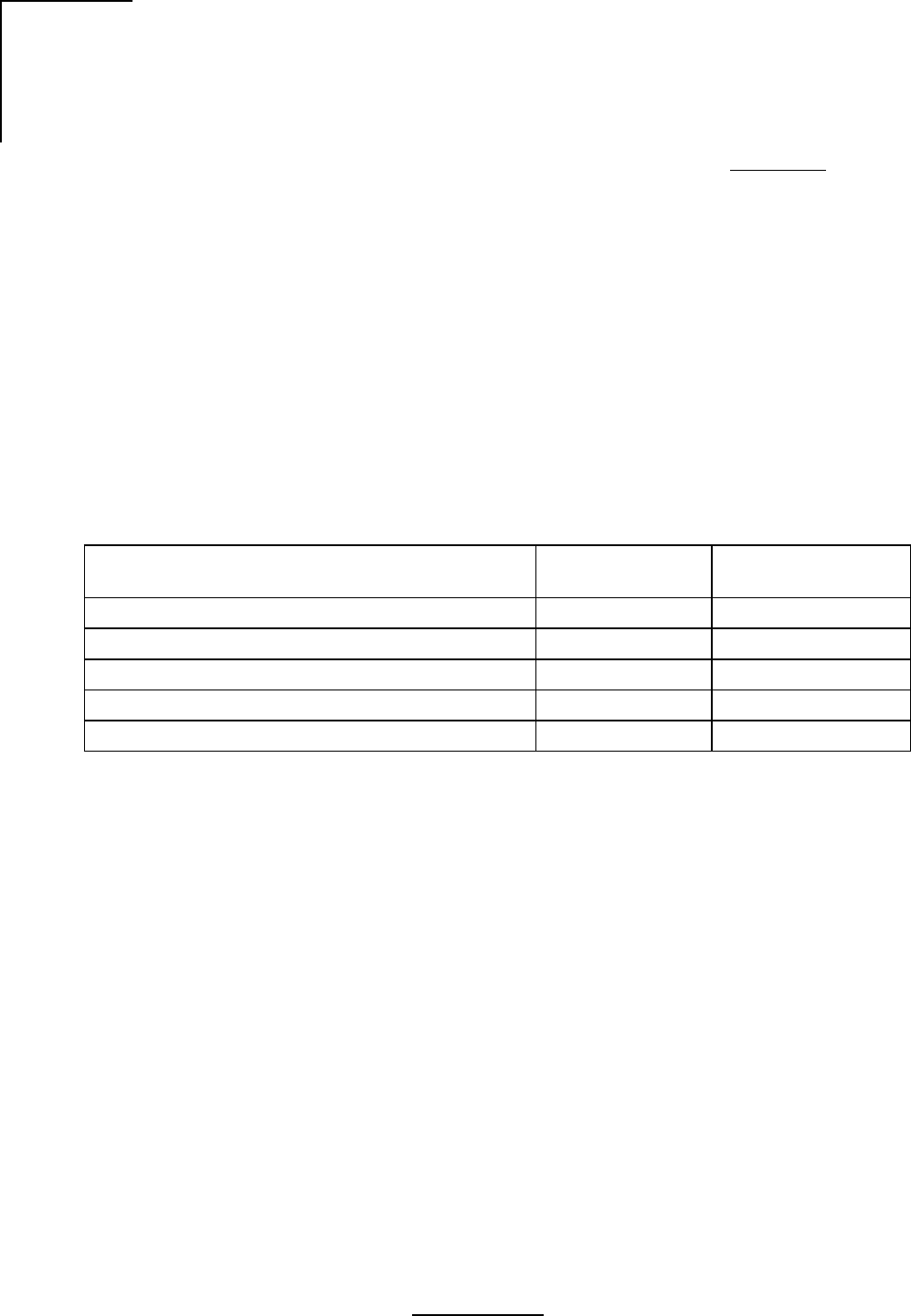
3.5 Commissioning
1. Visually verify that the N2-X Ethernet Extender is properly mounted.
2. Verify that the DC power input to the N2-X Ethernet Extender is on.
Refer to Table 3.4.
3.5.1 Configuring N2-X Ethernet Extender System Antennas
The antennas used on an N2-X Ethernet Extender radio system are generally configurable for
either vertical or horizontal polarization. It is extremely important to verify that both antennas
are configured for the same polarization, and that the appropriate antenna polarization has
been selected for the specific radio link.
Table 3.4 - Installation Checklist
tsilkcehCnoitallatsnI
?eruceserawdrahgnitnuomkcarehtsI
?dednuorgylreporptinuehtsI
?detcennocylreporpannetnaehtsI
?tcerrocdnaecalpnisnoitcennocatadehterA
519530LW
34
N2-X Ethernet Extender Installation and Operation Manual
3.5.2 Aligning the N2-X Ethernet Extender System Antennas
With the N2-X Ethernet Extender at each site properly configured for operation, antenna
alignment must be performed at both sites. Proper antenna alignment is crucial to the proper
operation of an N2-X Ethernet Extender radio system, and should only be accomplished by
experienced professionals.
The N2-X Ethernet Extender is equipped with a ODU mounted BNC-(f) RSSI connector to which
an analog or digital voltmeter can be connected. The voltage range at the test point, between
the center conductor of the connector and ground, varies from approximately two VDC to four
VDC, serving as a receive signal strength indicator (RSSI). The stronger the receive signal, the
higher the RSSI voltage. Refer to Table 3.5.
Emanating from a microwave antenna is a main beam (or lobe) of RF energy, surrounded by
RF side lobes. The beamwidth of the main beam varies with the size and type of antenna, as
well as the specific frequency of the RF signal, and is generally defined by the nominal total width
of the main beam at the half-power (-3 dB) points. Side lobes surround the main beam at specific
angle distances, and will be lower in power than the main beam.
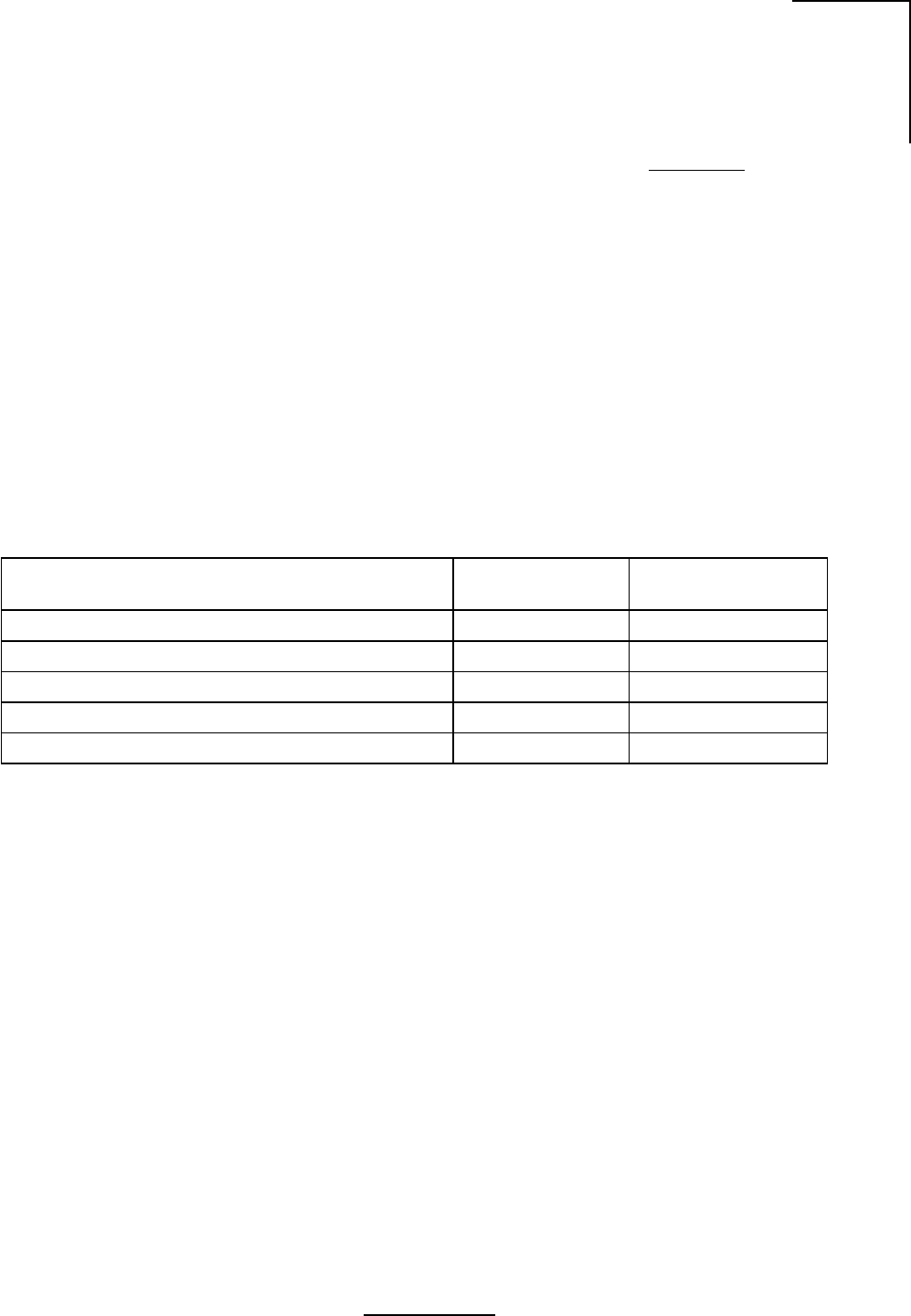
When aligning an antenna system, it is extremely important to verify that the antennas are both
aligned on the main beam, not on a side lobe. Referencing Table 3.6, the first side lobe will
generally be located at an angle slightly less than twice the antenna beamwidth.
Following the course alignment of an antenna system, a common practice when performing a
fine alignment is to slowly swing each antenna (one at a time!) in both vertical (elevation) and
horizontal (azimuth) planes to verify that the main beam and first side lobe can be accurately
identified. This insures that accurate alignment of the antenna system on the main beam has
been accomplished.
Each N2-X Ethernet Extender is shipped with an RSSI test sheet, showing the relationship
between the receive signal strength level (in dBm) and the RSSI level (in VDC). These RSSI
test sheets are often referred to as AGC Curves. The RSSI test sheets can be used to verify
that the calculated receive signal levels match up with the actual receive signal levels.
Substantial differences between calculated and actual levels could point to transmission
system problems, side lobe alignment, path obstructions, etc.
Table 3.5 - RSSI vs. Receive Signal Level
)mBd(leveLlangiSevieceR03-04-05-06-07-08-09-
)CDV(ISSR54.407.300.353.206.101.158.0
329102LW

35
N2-X Ethernet Extender Installation and Operation Manual
Table 3.6 - Approximation Table
elytSdnaretemaiDannetnA)iBd(niaG)seerged(htdiwmaeBBd3
cilobaraptoof-21.821.6
cilobaraptoof-42.031.3
lenaptalftoof-65.710.91
lenaptalftoof-21324.9
lenaptalftoof-425.727.4
619530LW

36
N2-X Ethernet Extender Installation and Operation Manual

37
N2-X Ethernet Extender Installation and Operation Manual
4.0 Maintenance and Troubleshooting
The N2-X Ethernet Extender contains static sensitive components, and has no user-service-
able parts.
4.1 N2-X Ethernet Extender Maintenance
The N2-X Ethernet Extender is designed to operate with no scheduled maintenance activities.
From a precautionary perspective, a regular check of power supply input voltages and RSSI
voltages should be planned by the user.
4.1.1 RSSI Voltage
The Wireless Customer Service department recommends a monthly check of the N2-X
Ethernet Extender’s RSSI voltage. Variations in the RSSI voltage could be an indicator of
antenna or antenna feed movement, loose or improper RF cabling or connectorization, path
obstructions or reflections, etc.
38
N2-X Ethernet Extender Installation and Operation Manual
4.2 Identifying and Resolving Receive Signal Strength Issues
There are a great number of items which can affect the transmission of a microwave signal from
one site to another. Every microwave path is unique, and must be evaluated for performance
before a radio link is installed.
Outside of radio equipment issues, antenna alignment, RF signal blockage, and multipath
fading are among the most common transmission problems experienced in the field.
4.2.1 N2-X Ethernet Extender Equipment Issues
Frequency Selection
1. Verify the transmit/receive frequency selection for each N2-X Ethernet Extender radio is
set appropriately, and that a “matched pair” of radios has been selected for the system.
Each N2-X Ethernet Extender terminal can be set to the frequencies listed in Table 4.1.
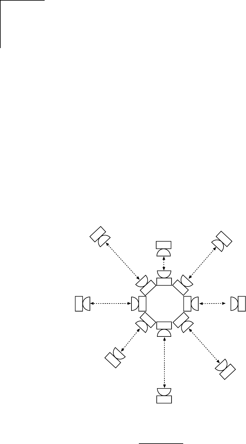
2. To reduce the possibility of co -adjacent channel interference, proper frequency coordi-
nation and antenna polarization is used to isolate each channel. The concept is to achieve
maximum RF isolation between link channels by means of frequency spacing and antenna
polarization. In a “star” configuration an optimum frequency and antenna polarization plan
is provided to demonstrate an example of maximum isolation between links (See Figure
4.1).
Figure 4.1 - Frequency Selection for the N2-X Ethernet Extender Radio
1H 1
2H
2
4H
4
3H
3
7V
7
8V
8
6V
6
5V
5
H = Horizontal Antenna Polarization
V = Vertical Antenna Polarization
WL035917
H
H
H
H
VV
V
V

39
N2-X Ethernet Extender Installation and Operation Manual
Table 4.1 - Frequencies
.oNlennahCycneuqerF
18062.5
'1865337.5
240172.5
'229547.5
382182.5
'361657.5
425192.5
'44667.5
567103.5
'546677.5
600213.5
'688687.5
742223.5
'721797.5
884233.5
'863708.5
819530LW

40
N2-X Ethernet Extender Installation and Operation Manual
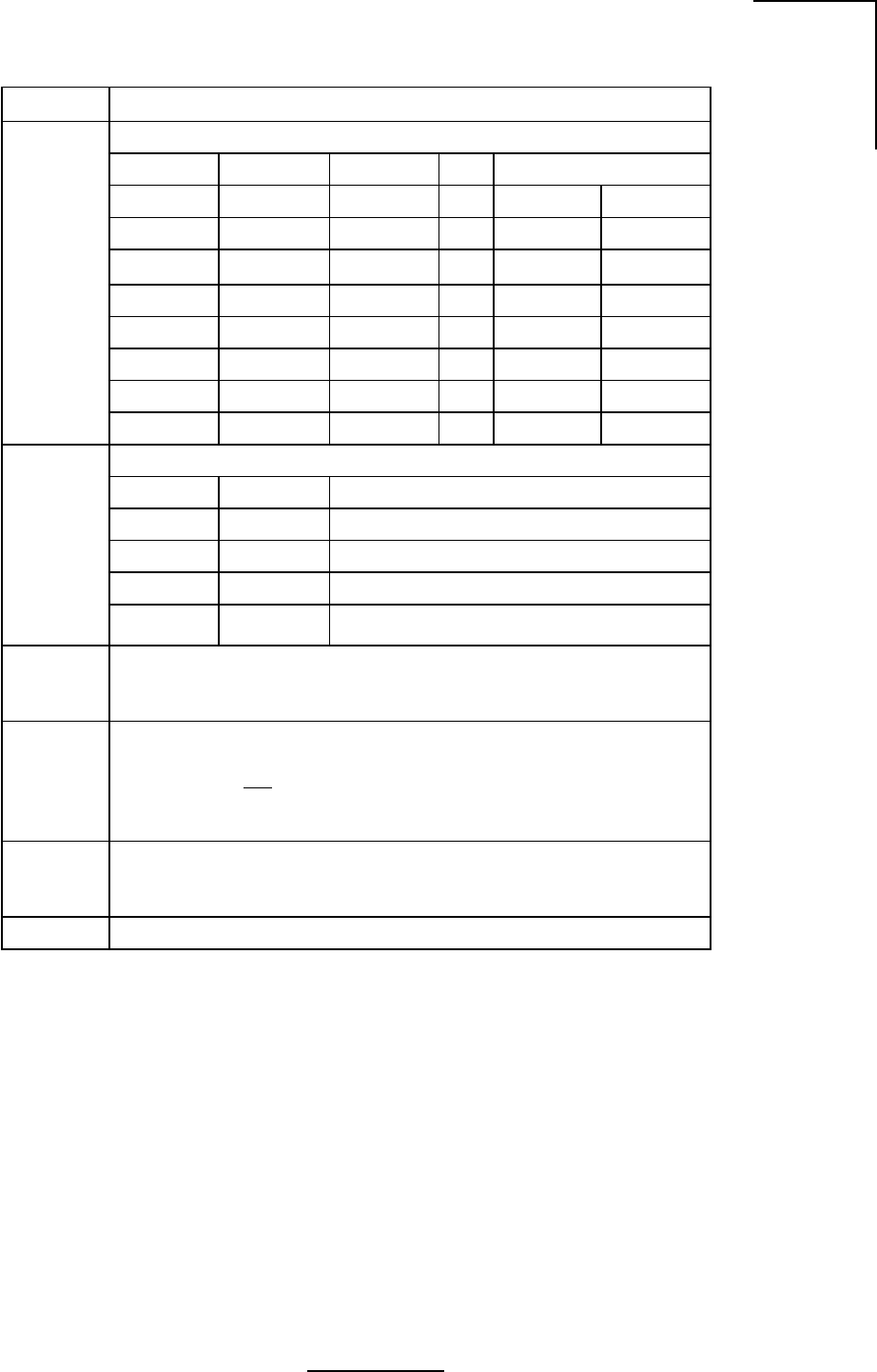
4.3 Dip Switch Function and Configuration
Refer to Table 4.2 below. Switches 1, 2 and 3 control Frequency and Channel selection.
Switches 4 and 5 are used for Transmit Power control. Switch 6 selects Ethernet Mode and
switch 8 controls Packet Filtering. Switches 9 and 10 are not used. Also refer to Figure 4.2 for
dip switch location information.
Note: Primary power must be cycled off, then on, for changes in DIP switch settings to take
affect.
hctiwSnoitcnuF
3dna,2,1
noitceleSlennahCdnaycneuqerF
1hctiwS2hctiwS3hctiwS.hC)zHG(riaPycneuqerF
ffOffOffO1 08062.586537.5
ffOffOnO2 40172.529547.5
ffOnOffO3 82182.561657.5
ffOnOnO4 25192.504667.5
nOffOffO5 67103.546677.5
nOffOnO6 00213.588687.5
nOnOffO7 42223.521797.5
nOnOnO8 84233.563708.5
5dna4
lortnoCrewoPtimsnarT
4hctiwS5hctiwSzHG7.5/zHG3.5troPannetnAtarewoPxT
ffOffOmBd21+
ffOnOmBd8+
nOffOmBd4+
nOnOmBd0+
6edoMtenrehtE
xelpuDflaH=ffO xelpuDlluF=nO
7
elbasiDUDI UDIotdetcennoceblliwUDO=ffO lliwUDO=nOton UDIotdetcennoceb
:etoN siti,tnempiuqelanretxeotegamadlaitnetoptneverpotredronI ehtotteseb7hctiwstahtevitarepmi nO .noitisop
8gniretliFtekcaP delbanegniretliFtekcaP=ffO delbasidgniretliFtekcaP=nO
01dna9desutoN
:etoN ninwohserasgnitteshctiwsPIDtluafedyrotcaF dlob .ecafepyt
109791LW
Table 4.2 - Dip Switch Configuration
41
N2-X Ethernet Extender Installation and Operation Manual
Figure 4.2 - Dip Switch Access and Configuration Information
WL201908
ON CTS
10987654321

42
N2-X Ethernet Extender Installation and Operation Manual
4.4 Where To Get Further Assistance
Your primary source of assistance is the support staff of the organization from which you
purchased this product. The Wireless, Inc. support staff should only be contacted directly if you
purchased this product directly from Wireless, Inc., or if you are unable to obtain sufficient
assistance from your primary support contact.
General Product and Company Information
Wireless, Inc.
5452 Betsy Ross Drive
Santa Clara, CA 95454-1101
USA
Tel.: +408 727 8383
Fax: +408 727 1259
E-mail: info@wire-less-inc.com
Website: www.wire-less-inc.com
Detailed Product Information, Sales/Pricing Information and Pre-Sales Technical
Support
Wireless, Inc.
Sales Department
5452 Betsy Ross Drive
Santa Clara, CA 95054-1101
USA
Tel: +408 727 8383
Fax: +408 727 0990
E-mail: sales@wire-less-inc.com
Website: www.wire-less-inc.com
Post-Sales Technical Support (Customer Service)
To assist you with field issues and, if necessary, to arrange for repair services, Wireless, Inc.'s
Customer Service department can be reached via telephone, facsimile, e-mail, mail, or through
our Website.

43
N2-X Ethernet Extender Installation and Operation Manual
4.5 Return Procedure
All material returned to Wireless, Inc. must be accompanied by a Return Material Authorization
(RMA) number from Wireless, Inc.'s Customer Service department. If you purchased your
Wireless, Inc. product through a distributor, the Wireless RMA number should be obtained
through the distributor. An RMA number is necessary to assure proper tracking and handling
of returned material at the factory. Wireless, Inc. reserves the right to refuse shipments not
accompanied by an RMA number. Refused shipments will be returned to the shipper via collect
freight.
To obtain an RMA number, contact Wireless, Inc. as follows:
Telephone: +408 727 8383
Fax: +408 727 1259
E-mail: customerservice@wire-less-inc.com
The following information will be required to issue an RMA number:
•Part Number
•Serial Number
•Failure Description
•Contact person, telephone, and fax numbers
•Ship-to address
•Bill-to address*
•Customer purchase order* (P.O.) or reference number
* Required for non-warranty repair services. For non-warranty repair services, an RMA
number will be issued when Wireless, Inc. acknowledges the purchase order.
Important - All non-U.S. returns must include 5 copies of proforma/customs invoice for each
shipment which lists:
•RMA number
•Value of items
•Description of items (including the Wireless model or part number)
Please send all returns to:
Wireless, Inc.
Attn: RMA Department
5452 Betsy Ross Drive
Santa Clara, CA 95054-1101
USA
RMA No. __________
The customer is responsible to properly label and package repairs and prepay shipping to
Wireless, Inc. If possible, the original packaging material should be used to return electronic
parts. The RMA number must be visible on the outside of all packages returned. Unless other
arrangements have been made, all repairs are shipped back to the customer prepaid via ground
carrier.

44
N2-X Ethernet Extender Installation and Operation Manual

A-1
N2-X Ethernet Extender Installation and Operation Manual
Appendix A Grounding Practices and Lightning
Protection Information
General
Good grounding (“earthing”) practices, when used in telecommunications, have some direct
benefits which can help you maximize the up time of your system as well as ensure the safety
of those people working on the system. Among these benefits are:
1. Protection of personnel from electric shock and fire hazards.
2. Reduction of radiated and conducted electromagnetic susceptibility.
3. Improved system tolerance to discharge of electrostatic energy and lightning interference.
4. Minimized service interruptions and service damage.
There is no practice or formula which can completely eliminate the above risks, but we at
Wireless, Inc. believe that good grounding and bonding practices can significantly reduce the
risk of many of these hazards. We have included a bibliography at the end of this appendix which
contains several publications that are readily available and contain detailed information on
many aspects of grounding systems and their design, implementation, measurement, and
maintenance.
Please note that every telecommunication site is unique, and must be evaluated accordingly.
The following information is provided for generic reference and educational purposes only. The
grounding plans and practices for a given site should only be established and accomplished by
trained professionals, working in accordance with local practices and regulations.
Ground Connections
There should be a grounding plan designed at the outset of site design in order to provide the
best grounding procedures and to minimize ground loop currents. This should be achieved by
connecting the outer conductors of the cables through a large section copper strap to a central
grounding point and the size of the conductor should be increased as each branch path is
added. The final conductor should be connected directly to the grounding system. For a radio
site a single copper grounding rod is insufficient because its impedance is likely to be too high.
Lightning Protection
Radio sites can be particularly prone to lightning strikes by virtue of their normally exposed
locations and the presence of relatively tall antenna support structures.
It is not possible to provide and guarantee complete protection from the effects of lightning;
however, they can be significantly reduced by careful attention to grounding, protection
devices, and the layout of the site itself.
Reference should also be made to various publications, some of which are listed in the
Bibliography. Where any site owner or user is in doubt about the protection requirements for any
particular location, the appropriate authority should be consulted.

A-2
N2-X Ethernet Extender Installation and Operation Manual
Protection Arrangements
The purpose of any protection arrangement should be to provide a suitable path to ground for
the lightning current, to ensure adequate bonding between structures and all metalwork on the
site and the common grounding system in order to reduce the side flashing, and to attempt to
prevent the entry of flashes or surges into the building.
The resistance to ground should be kept to a minimum and a value of less than 10-ohms is
recommended. The most important feature is that the system should ideally be at equal
potential across the entire site.
Certain authorities and service providers have their own particular practices which have to be
followed where applicable.
Arrangements will vary considerably from very simple sites to complicated sites with multiple
buildings, antenna support structures and associated equipment, and may involve integration
with existing systems. Such systems may require upgrading.
Lightning conductors
Down conductors, bonding interconnections, ground rings and radial tapes should be of
uninsulated 000 AWG copper cable or solid copper tape with a minimum cross section of 25 x
3 mm with all connections protected by non reactive paste.
Protected test points should be included if appropriate, and sacrificial ground lugs should be
clearly marked and easily accessible for periodic inspection.
Grounding of antenna support structures
A structure will generally act as its own lightning conductor and therefore will not require an
additional conductor from the top to the base. A lightning rod may be required to extend the zone
of protection to protect equipment mounted on the top of the structure. The lightning rod should
extend 2.5-meters above the highest equipment.
Ground mounted support structures should be connected at their base to a ground ring via
sacrificial ground lugs. Towers should have a connection from each leg.
A ground ring should consist of copper cable or solid copper tape with ground rods equally
spaced at 2-meter intervals around the base of the structure as close to it as possible, buried
approximately 0.6-meters deep where soil conditions allow. An alternative method using radials
rather than rings is detailed in “The ‘Grounds’ for Lightning and EMP Protection”, second
edition, published by PolyPhaser Corporation.
The ground ring should be connected to the main building ground by the most direct route,
buried as appropriate.
Roof mounted structures should be connected to the main building ground by the most direct
route using sacrificial lugs and copper cable or tape as appropriate. Tower guy wires should be
directly bonded at their lowest point to a suitable ground electrode or connected to the site
ground by the most direct route.

A-3
N2-X Ethernet Extender Installation and Operation Manual
Grounding of feeders
All antenna feeders should be bonded to the tower at the upper and lower ends and grounded
at the point of entry into the building. Weatherproof grounding kits are available from antenna
manufacturers.
Note: Many of the cables used by Wireless, Inc. have braided rather than solid outer
conductors; this type of grounding is not appropriate. In these cases we recommend the
use of Wireless, Inc. approved lightning arrestors. For information on lightning arrestors,
please contact Wireless, Inc.’s Customer Service department.
Grounding of buildings
A ground ring ideally should surround the building and be connected to individual grounds
associated with feeder entry, antenna support structure, building lightning conductor, equip-
ment room, main AC supply and other facilities. Each connection should be made by the most
direct route in order to minimize interaction between the different grounding functions.
The ground ring should consist of copper cable or tape with electrodes 2- meters or greater in
length, buried to a depth of 0.6-meters and at a distance from the building not to exceed 1-meter.
Buildings may require lightning rods where they are not within the zone of another protected
structure.
BIBLIOGRAPHY
ITU - T K.40 Protection against LEMP in telecommunications centres
ITU - T K.27 Bonding configurations and earthing inside a telecommuni-
cation building
ITU - T K.35 Bonding configurations and earthing at remote electronic
sites
ITU - T K.39 Risk assessment of damages to telecommunications sites
due to lightning discharges
ITU - T Lightning Handbook The protection of telecommunication lines and equipment
against lightning discharges
IEEE Emerald Book - Powering and Grounding
The “Grounds” for Lightning and EMP Protection, second edition
Published by PolyPhaser Corporation

A-4
N2-X Ethernet Extender Installation and Operation Manual
B-1
N2-X Ethernet Extender Installation and Operation Manual
Appendix B Installation Instructions
Read the instructions completely before assembling or installing the antenna. This installation
can be dangerous and requires qualified personnel familiar with microwave assembly and
installation.
Site Planning
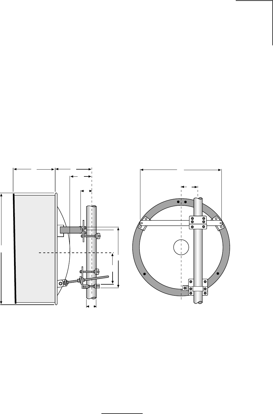
1. For antenna mounting and planning dimensions, see Figure B.1 and Table B.1.
2. The antenna is normally assembled with an elevation adjustment range of +50 degrees to
-5 degrees. By inverting the mount, it can be assembled with a +5 degree to -50 degree
range. In either configuration, the antenna centerline can be offset right or left, relative to
the vertical mast pipe (See Figure B.2) by inverting the Horizontal Tube Assembly.
Figure B.1 - Two Foot Diameter Antenna
WL035927
JH
B
A
P
K
G
Q
D
C

B-2
N2-X Ethernet Extender Installation and Operation Manual
Table B.1 - Two Foot Diameter Antenna Dimensions
noisnemiDnoitpircseDannetnA)mm6.0(.tf2annetnA)mm8.0(.tf5.2
AhtgneLtnuoM)mm075("4.22)mm017("9.72
BtnioPtoviP)mm501("2.4)mm501("2.4
CtesffOeniLretneC)mm521("0.5)mm521("0.5
DturtStnuoMlatnoziroHA/NA/N
EturtStnuoMlacitreV.tP.tvP)mm571("8.8)mm012("3.8
FturtSediSdexiFlatnoziroHA/NA/N
GenilretneCannetnA)mm543("6.31)mm524("8.61
HhtgneLrotcelfeR)mm513("3.21)mm063("3.41
JhtgneLduorhStrohS)mm023("5.21)mm063("3.41
htgneLduorhSgnoL)mm583("1.51)mm053("8.51
KretemaiDannetnA)mm537("0.92)mm098("53
L)dradnatS(htgneLemodaR)mm043("4.31)mm524("8.61
NhtpeDturtStnuoMA/NA/N
PxetreVrotcelfeR)mm091("6.7)mm022("7.8
QretemaiDtsaM)mm511-06("5.4"4.2)mm511-06("5.4"4.2
egnaRelbatsujdAhtumizA °5-/+ °5-/+
segnaRtnemtsujdAnoitavelE °5-/°05+ °5-/°05+
829530LW
B-3
N2-X Ethernet Extender Installation and Operation Manual
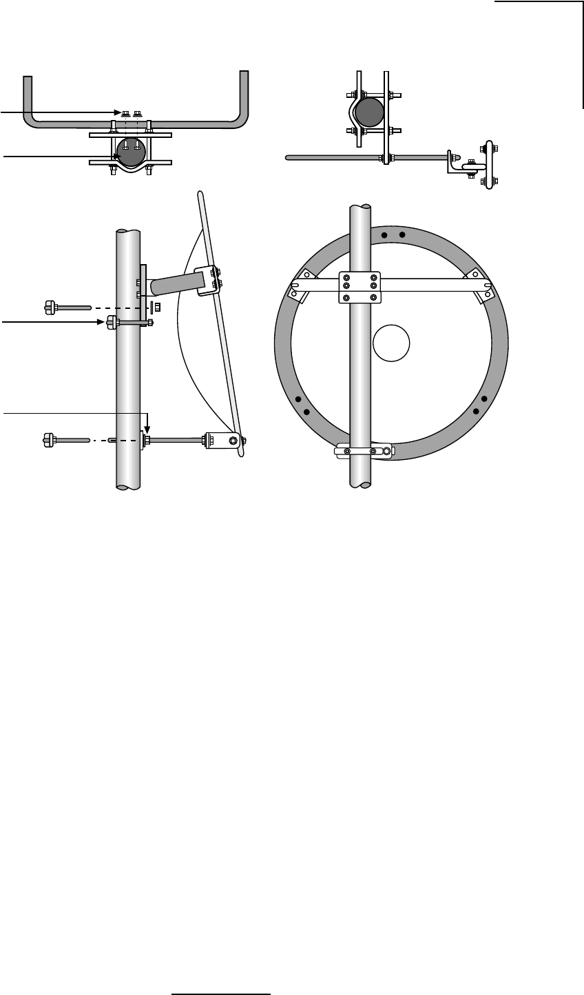
Figure B.2 - Mount Configuration
WL035929
and Nut (4)
3/8” (10mm)
Round Head
Screw Lockwasher
ø 2.4”- 4.5”
(60-115mm)
Shear Stop
Collar
Elevation
Plate
B-4
N2-X Ethernet Extender Installation and Operation Manual
Table B.2a - Contents List, Reflector Assembly
Unpacking and Preparation
1. Carefully unpack the reflector, mount, shroud (if any), radome (if any) and feed from the
crate. For correct antenna performance, handle all components with care. Set aside the
packaged feed and any shroud or radome. See Figures B.3 through B.6.
Caution: The reflector spinning has been formed to a very close-toleranced parabolic shape.
Careful handling and assembly is required to avoid denting or deforming the reflector,
which would degrade the antenna's performance.
2. Inspect for any damaged parts. See Tables B.2a-B.2d for an inventory of the parts and
hardware shipped with the antenna.
Shroud Attachment
Attach the shroud assembly that is provided with high-performance antennas to the reflector.
The installation procedure is covered by another instruction sheet supplied with the shroud.
Note: Some models have the shroud factory installed.
Table B.2b - Contents List, Feed Assembly
rebmuNtraPnoitpircseD.ytQkcehC
3-23832A2-nepO'2ES.yssA.lfeR1
039530LW
rebmuNtraPnoitpircseD.ytQ
1-63752pmalCgnitnuoMdeeF4
305-61762058.5-052.5A/SdeeF1
0715TDA071SSD'04x8//7x61/3lytuBkcarTRR1
0500XWF560.x437.0W"4/1rehsaW4
122-IIsnoitcurtsnInoitallatsnI1
0600XUNtuNxeH4
0500XWSrehsaWtilpS4
139530LW
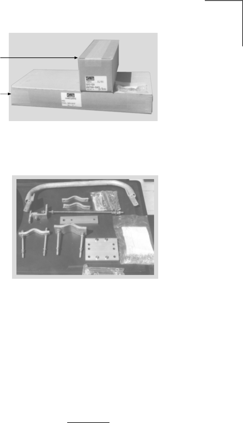
B-5
N2-X Ethernet Extender Installation and Operation Manual
Figure B.3 - Mounting Hardware Packed
Figure B.4 - Mounting Hardware Unpacked
WL035932
Feed Horn
Assembly
Mounting
Hardware
WL035933

B-6
N2-X Ethernet Extender Installation and Operation Manual
Table B.2c - Contents List, Mount Assembly
rebmuNtraPnoitpircseDytQ
105-57652ylbmessAepiPlatnoziroH 1
505-52752ylbmessAgnipmalCtsaM 1
2-61322vlaGdoRdedaerhT2
5-52542"1flaHpmalCtsaM1
0210GWFvlaGrehsaW2
1210GUNvlaGrehsaW6
0900GWSvlaGrehsaWtilpS4
905-52732yssAgnipmalCtsaM 1
2-61322vlaGdoRdedaerhT2
8-52542flaHpmalCtsaM1
0210GWFvlaGrehsaW2
0210GUNtuNxeH6
0900GWSvlaGrehsaWtilpS4
405-72752yssApotSraehS 1
3-58232doRdedaerhT2
2-52542trohS-flaHpmalCZA2
0310XUNtuNxeH6
0900GWSvlaGrehsaWtilpS4
305-03752yssAdoRnoitavelE 1
6-11632doRnoitavelE1
105-24832yssAtkrBdoRnoitavelE1
1-66652elgnAtroppuSnoitavelE1
0800GOBvlaGtloBxeH1
0210GWFvlaGrehsaW1
0410GWFvlaGrehsaW1
0210GUNvlaGtuNxeH1
5910XUNSStuNxeH4
0900GWSvlaGrehsaWtilpS1
0010GWSvlaGrehsaWtilpS1
439530LW

B-7
N2-X Ethernet Extender Installation and Operation Manual
Table B.2d - Contents List, Mount Assembly
rebmuNtraPnoitpircseD.ytQ
105-33752 tiKerawdraHtnuoM1
45-94701.vlaGtloB-U2
2-16532recapS2
5000MDAebuT.zo1ezieS-itnA1
1290XOBtloBxeH6
0210GWFrehsaW4
05000XWFrehsaW21
0210GUN.vlaGtuNxeH4
0600XUN.vlaGtuNxeH6
0900GNPtunlaP4
0500XWS.vlaGrehsaWtilpS6
1-09562 etalPnoitavelE1
1-19562 etalPhtumizA1
6811XOB wercSDHDNR4
0310XUN tuNxeH4
0800XWS rehsaWtilpS4
232-II snoitcurtsnInoitallatsnI1
539530LW
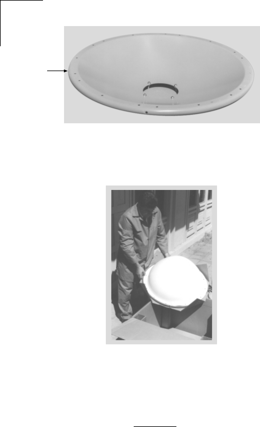
B-8
N2-X Ethernet Extender Installation and Operation Manual
Figure B.5 - Parabolic Reflector
Figure B.6 - Unpacking the Radome
WL035936
Parabolic
Reflector
WL035937
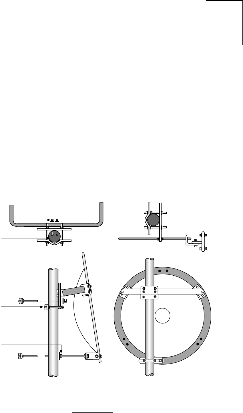
B-9
N2-X Ethernet Extender Installation and Operation Manual
Figure B.7 - Antenna Mount Assembly
Mount Assembly and Attachment
1. The reflector should be placed face down, either on the shroud or blocked up on packing
lumber. Locate the Top and Bottom markings stenciled onto the back of the reflector.
2. Loosely attach Top Support Angles to the Horizontal Tube Assembly as shown in Figure
B.7 and B.8.
3. For desired mount configuration (refer to Figure B.2), attach the Vertical Tube Assembly
to the Horizontal Tube Assembly as shown in Figure B.7 and B.8.
4. Verify proper assembly of the elevation rod hardware as shown in Figure B.9. Remove
outer hardware and insert rod through elevation plate.
Important: For elevation angles grater than ±20°, Beveled Washers, shown in Figure B.9,
must be used. However, beveled washers may be used for elevation angles greater than
±10°.
5. Carefully place mount assembly onto antenna backring, taking care not to damage the
reflector. Loosely fasten the Top Support Angles and the Elevation Support Angle to the
antenna backring using 1/2” hardware as shown in Figure B.7.
6. Verify alignment of the Vertical Assembly with the vertical axis of the reflector and secure
the Top Support Angles and the Elevation Support Angle to the ring.
WL035938
and Nut (4)
3/8” (10mm)
Round Head
Screw Lockwasher
ø 2.4”- 4.5”
(60-115mm)
Shear Stop
Collar
Elevation
Plate

B-10
N2-X Ethernet Extender Installation and Operation Manual
Figure B.9 - Elevation Rod Assembly
Figure B.8 - Antenna Mount Assembly
WL035939
WL035940
Secure Antenna to Mast
Pipe using large and
small Mast Clamps
Attach Shear Stop
Collar on Mast Pipe so
that it will be Under
Azimuth Plate
Position Elevation Plate
on the Mast so elevation
screw is horizontal when
Antenna is aligned

B-11
N2-X Ethernet Extender Installation and Operation Manual
Feed Installation
Following the instructions provided with the feed assembly, install the feed in the reflector. Refer
to Figures B.10 through B.14.
Figure B.10 - Feed Horn Installation
Clamp
1/4”-20
Hex Nut
Horizontal
H
V
Graphite
Grease
Hex Nut,
Lockwasher,
Flat Washer
Feed
Support Reflector
H
V
Vertical
WL035941
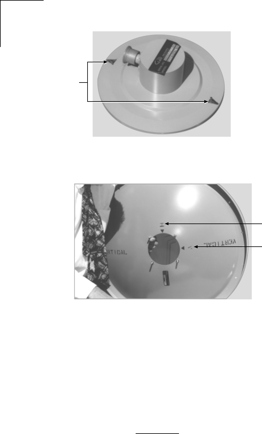
B-12
N2-X Ethernet Extender Installation and Operation Manual
Figure B.11 - Feed Horn Polarization Markings
Figure B.12 - Parabola Rear View Showing Polarization Reference Markers
WL035942
Feed Horn
Polarization
Markings
WL035943
Horizontal
Polarization
Marking
Vertical
Polarization
Marking
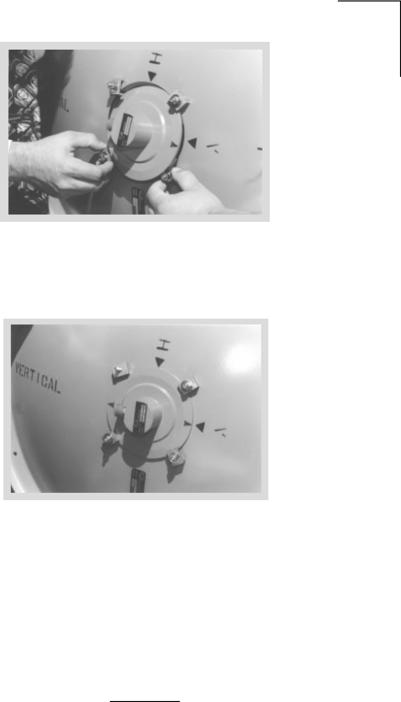
B-13
N2-X Ethernet Extender Installation and Operation Manual
Figure B.13 - Feed Horn Installation
Figure B.14 - Feed Horn Installation for Vertical Polarized Operation
WL035945
WL035944
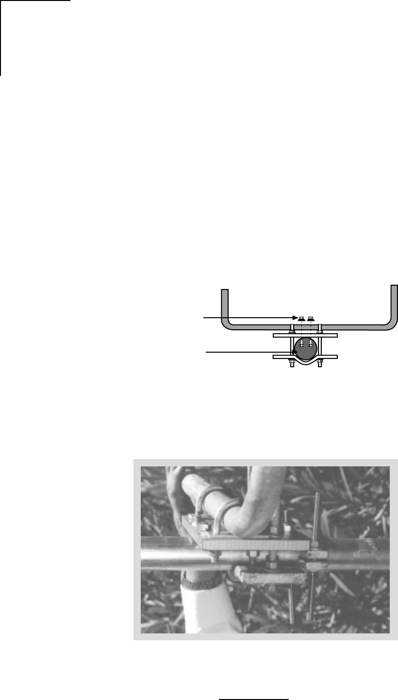
B-14
N2-X Ethernet Extender Installation and Operation Manual
Figure B.16 - Azimuth Adjustment Clamp Assembly
Radome Installation
Molded Radomes (normally optional on standard antennas) should be installed following the
instructions provided.
Azimuth Adjustment Clamp/Shear Stop Installation
1. Verify proper assembly of the azimuth clamp/shear stop clamp as shown in Figure B.15
and B.16. Securely attach the shear stop clamp to the mast pipe as shown, orienting it as
nearly as possible to the antenna boresight direction, and square to the mast axis. Note
that the shear stop clamp used on the two foot antennas also provides the azimuth
adjustment.
2. Refer to Figure B.1 for the position of the antenna centerline relative to the shear stop
clamp. The clamp must be mounted to provide support during installation and azimuth
adjustment.
Figure B.15 - Azimuth Clamp/Shear Stop Assembly
3/8” (10mm)
Round Head
Screw Lockwasher
and Nut (4)
ø 2.4” - 4.5”
(60-115mm)
WL035946
WL035947
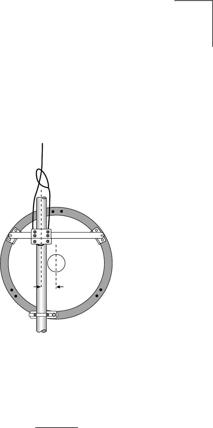
B-15
N2-X Ethernet Extender Installation and Operation Manual
Antenna Hoisting and Installation
1. Attach a hoist strap around the vertical assembly or the horizontal assembly as shown in
Figure B.17. Do not hoist by the elevation rod. Make sure that the vertical assembly is
unobstructed where it will mount against the mast pipe.
2. Attach tag lines and carefully lift the antenna into position, resting the vertical assembly on
the shear stop clamp.
3. Fasten the mount to the mast pipe with 1/2” U-bolts. The antenna must be free to rotate
during azimuth adjustment, so tighten only enough to close the gap between the mast and
vertical channel. Do not leave the antenna loose for any extended period of time, i.e.
overnight.
Figure B.17 - Hoisting the Antenna
WL035948
5”
(127mm)

B-16
N2-X Ethernet Extender Installation and Operation Manual
General Antenna Alignment Procedures
Normally the antenna is aligned by performing azimuth and elevation adjustments and
elevation adjustments as necessary until the peak signal is obtained. It may be helpful to re-
peak one adjustment before finalizing or locking down the other.
Warning: Damage to the antenna can occur if azimuth or elevation adjustments are
attempted without loosening the proper connections as described in the following steps.
Azimuth Adjustment
1. Be sure the mast pipe U-bolts are just loose enough to allow mount rotation while
maintaining complete contact between the mount and the mast pipe.
2. Turn the long stainless steel azimuth screws against the mounting channel. By alternately
turning one azimuth adjustment screw out and the other in, the antenna can be rotated to
the desired azimuth angle. Approximately 1 turn changes the azimuth direction by 1°. Avoid
adjusting the antenna beyond the ±5° provided by the azimuth clamp as this can damage
the adjusting hardware. Fasten the antenna to the mast pipe and reposition the clamp if
needed.
Note: By securing the mount to the mast pipe and realigning the azimuth clamp with the
antenna boresight, more reliable and precise azimuth adjustments can be achieved.
After all adjustments are made, tighten both of the azimuth screws against the channel and
secure with the lock nuts provided.
3. Tighten the mast pipe U-bolts while maintaining the peak signal by alternating from left to
right in 1/4 turn intervals.
Elevation Adjustment
1. Insure that both of the bolts connecting the mount to the Top Support Angles and the
pivoting Elevation Angle (refer to Figures B.7 and B.9) are just loose enough to allow
resisted rotation.
2. Back the outer nuts on the elevation rod away from the bottom mount plate to allow some
fine adjustment range.
3. Turn the inside nut (with flat washer) on the elevation rod to adjust the elevation angle.
Approximately 5 turns changes the elevation by 1°. Remember, for elevation greater than
20°, install the two beveled washers as shown in Figure B.9.
4. After all adjustments are made, lock the nut against the bottom mount plate. Tighten the
angle pivot bolt and support bracket bolts.
Important: Be sure to tighten all hardware after final adjustments and insure that split
lockwashers, palnuts, or jam nuts are used where provided.

B-17
N2-X Ethernet Extender Installation and Operation Manual
Table B.3 - Nut Tightening Procedures
Inspection and Maintenance
1. Before leaving the installation, check that all hardware on the mount, shroud, radome, and
feed is tight and that nuts are locked in place.
2. Inspection of the antenna should be performed at lease once a year to check its condition
and to insure safe operation and maintenance. Qualified personnel, knowledgeable and
experienced in antenna installations, are required for this inspection.
Supplemental Information
Table B.3 is provided for installers unfamiliar with adequate nut tightening procedures for use
on stainless steel bolts, U-bolts, galvanized bolts or any bolts without the ASTM-”A325” marking
on the head. Disregard these recommendations when specific tightening requirements are
given.
Note: It is not recommended to reuse a palnut that has already been fully tightened or
deformed in any way. It should be replaced by a new palnut.
Weather Proofing the Type N Female Connector on Feeds
Remove the protective cover from the end of the feed and mate the connectors, screwing the
male connector firmly onto the feed.
Important: After connecting the coaxial cable, wrap the Type N connector with the gray butyl
rubber, squeezing it firmly around all joints to make a continuous seal. Finish the
weatherproofing by wrapping the butyl rubber with several layers of black PVC tape (not
supplied).
eziStloBlanimoNeuqroTtuNeuqroTtunkcoLtunlaP
"4/1.bl/.ni05.bl/.ni04
"61/5.bl/.ni201.bl/.ni06
"8/3.bl/.tf51.bl/.ni58
"61/7.bl/.tf42.bl/.tf51
"2/1.bl/.tf73.bl/.tf61
"8/5.bl/.tf47.bl/.tf82
"4/3.bl/.tf571.bl/.tf44
"8/7.bl/.tf212.bl/.tf15
"1.bl/.tf813.bl/.tf95
059530LW

B-18
N2-X Ethernet Extender Installation and Operation Manual
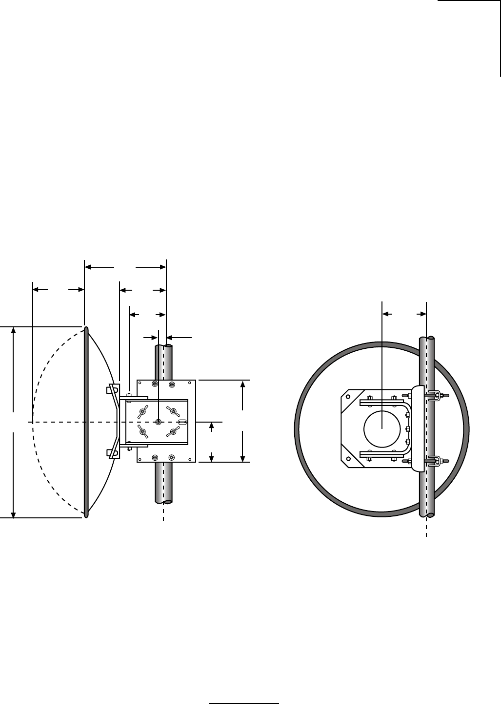
C-1
N2-X Ethernet Extender Installation and Operation Manual
Appendix C Quick Align Antenna Mount Installation
Read the instructions completely before assembling or installing the antenna. This installation
can be dangerous and requires qualified personnel familiar with microwave assembly and
installation.
Site Planning
1. For antenna mounting and planning dimensions, see Figure C.1.
2. The antenna is normally assembled with an elevation adjustment range of +50 degrees to
-5 degrees. By inverting the mount, it can be assembled with a +5 degree to -50 degree
range. In either configuration, the antenna centerline can be offset right or left, relative to
the vertical mast pipe (See Figure C.2) by inverting the Horizontal Tube Assembly.
Figure C.1 - Quick Align Antenna
4.8
(120)
9.3
(235)
4.5
(115)
4.9
(125)
3.8
(95)
.8
(20)
9.5
(240)
WL340902
7.1
(180)
25.8
(655)
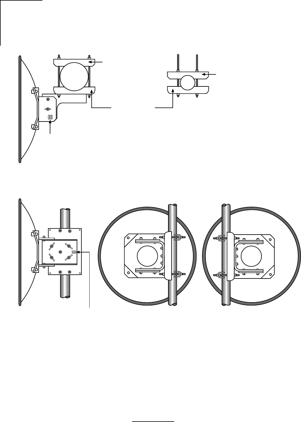
C-2
N2-X Ethernet Extender Installation and Operation Manual
Figure C.2 - Mount Configuration
Top View
Side View Rear View (Left Offset)* Rear View (Right Offset)*
* To change offset, invert antenna.
WL340901
Elevation
Adjustment
Slots
Saddle Brackets
Mast Clamp Kit for
1.9 (48mm) thru
4.5 (114mm) OIA Masts Re-Assemble Mast Clamp Kit
as Shown for 1.9 (48mm) OIA Masts
Azimuth
Adjustment
Slots

C-3
N2-X Ethernet Extender Installation and Operation Manual
Unpacking and Preparation
1. Carefully unpack the reflector, mount, shroud (if any), radome (if any) and feed from the
crate. For correct antenna performance, handle all components with care. Set aside the
packaged feed and any shroud or radome.
Caution: The reflector spinning has been formed to a very close-toleranced parabolic shape.
Careful handling and assembly is required to avoid denting or deforming the reflector,
which would degrade the antenna's performance.
2. Inspect for any damaged parts. See Tables C.1 and C.2 for an inventory of the parts and
hardware shipped with the antenna.
Table C.1 - Contents List, Quick Align Mount
rebmuNtraPnoitpircseD.ytQ
115-52752ylbmessApmalCtnuoM2
100-42762tekcarBtoviP1
100-52762tekcarBelddaS1
2680XOBSS"1x02-4/1tloBraCdHdnR9
0500XWFSS560.x437.0W"4/1rehsaW9
A832-IIsnoitcurtsnInoitallatsnI1
0600XUNSS02-4/1tuNxeH9
0500XWSSS4/1rehsaWtilpS9
1-18462lebaLgnidnePtnetaP1
429102LW
Table C.2 - Contents List, Reflector Assembly
rebmuNtraPnoitpircseD.ytQ
305-47762'2ylbmessArotcelfeR1
529102LW
Mount Assembly and Attachment
Assemble the panel mount according to Figure C.2. Orient Antenna using instructions supplied
with the antenna. Antenna models used with this mount may be circular, square or diamond
shaped. To change the offset of the antenna, unbolt the mount from the antenna, invert the
mount and reattach to the antenna.

C-4
N2-X Ethernet Extender Installation and Operation Manual
Loosen the azimuth or elevation locking hardware while maintaining sufficient friction to prevent
unwanted slippage. See Figure C.3.
Insert flat blade screw driver into slot “B” and pry in direction of the arrow or into slot “A” and pry
in opposite direction, as shown in Figure C.3. Stop prying approximately at position shown as
new overlapping slot in bottom plate becomes sufficiently visible when viewed through slot “A”.
Figure C.3 - Azimuth and Elevation Planning
ABAB
Top View
Sectional View
Sectional View
Top View
WL035952
ABAB

C-5
N2-X Ethernet Extender Installation and Operation Manual
Insert Screw Driver into slot “A” and pry in direction of the arrow, as shown in Figure C.4. Stop
prying approximately at position shown as new slot in bottom plate becomes sufficiently visible
when viewed through slot “B”. Continue alternating slots and prying in either direction until
desired alignment is obtained. Lock down hardware securely before leaving the site.
Figure C.4 - Azimuth and Elevation Planning
AB
AB
Top View
Sectional View
WL035953
AB
AB
Sectional View
Top View

C-6
N2-X Ethernet Extender Installation and Operation Manual
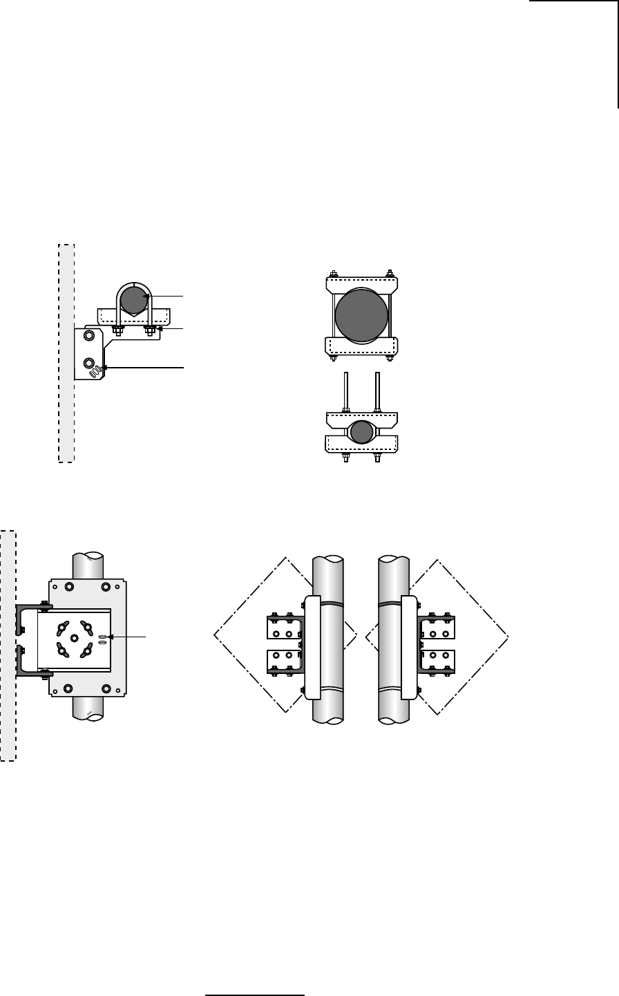
D-1
N2-X Ethernet Extender Installation and Operation Manual
Appendix D Adjustable Panel Antenna Mount
Assemble the panel mount according to Figure D.1. Orient Antenna using instructions supplied
with the antenna. Antenna models used with this mount may be circular, square or diamond
shaped. To change the offset of the antenna, unbolt the mount from the antenna, invert the
mount and reattach to the antenna.
Figure D.1 - Antenna Mount
2 3/8” (60mm)
DIA Mast
(2) 1/4” U-Bolt w/
Washer, Lockwashers
and Nuts
Azimuth Adjustment
Slots
Top View Optional Mast Clamp Kit
for 1.9” (48mm) DIA thru
4.5” (114mm) DIA Masts
Side View
Elevation
Adjustment
Slots
Rear View
Offset Left Rear View
Offset Right
WL035951
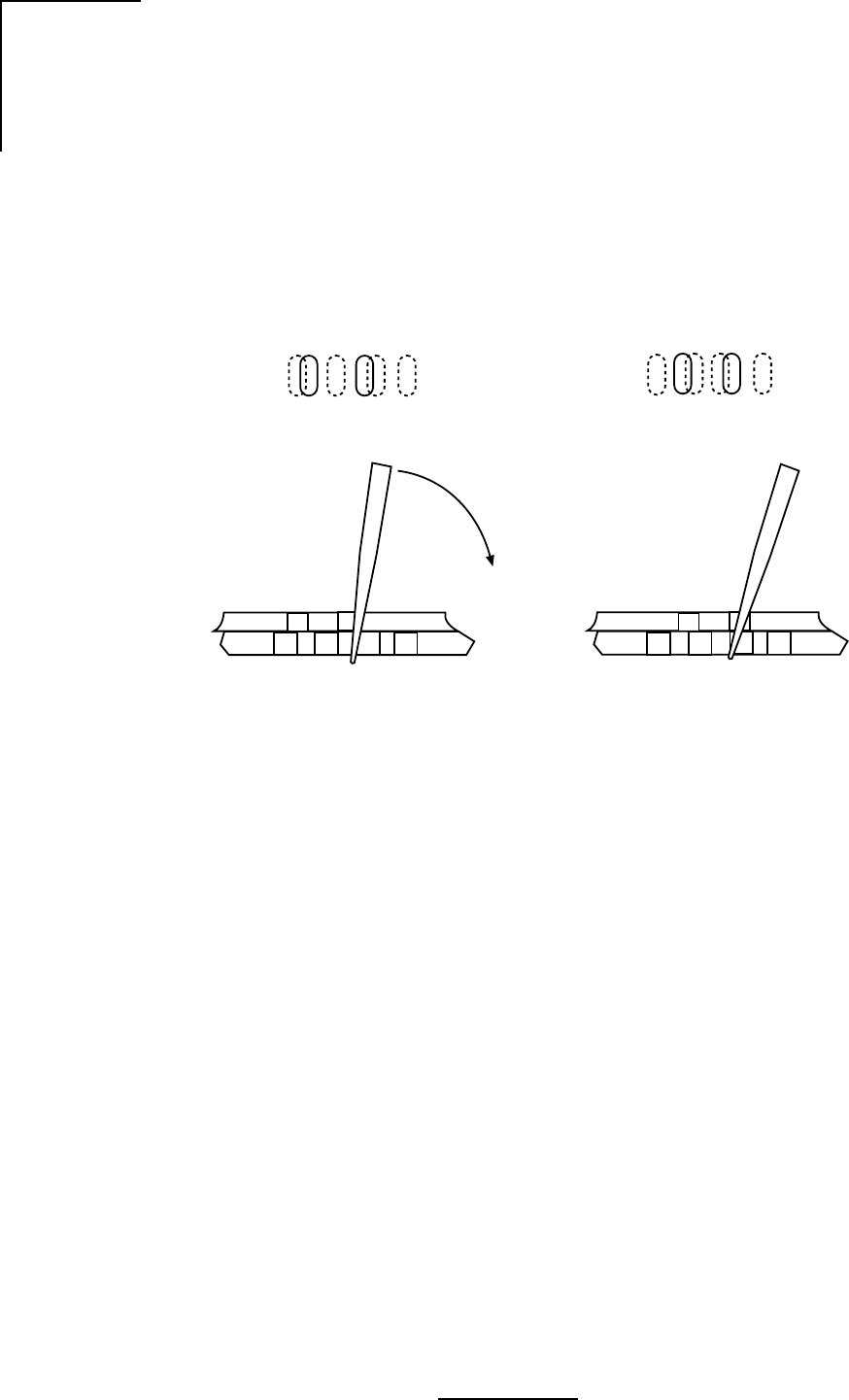
D-2
N2-X Ethernet Extender Installation and Operation Manual
Loosen the azimuth or elevation locking hardware while maintaining sufficient friction to prevent
unwanted slippage. See Figure D.2.
Insert flat blade screw driver into slot “B” and pry in direction of the arrow or into slot “A” and pry
in opposite direction, as shown in Figure D.2. Stop prying approximately as new overlapping
slot in bottom plate becomes sufficiently visible when viewed through slot “A”.
Figure D.2 - Azimuth and Elevation Planning
ABAB
Top View
Sectional View
Sectional View
Top View
WL035952
ABAB
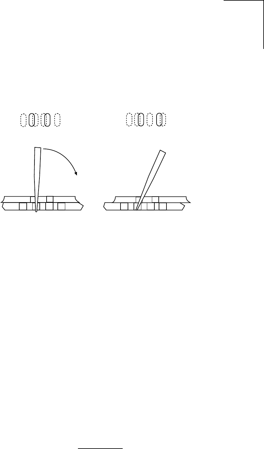
D-3
N2-X Ethernet Extender Installation and Operation Manual
Insert Screw Driver into slot “A” and pry in direction of the arrow, as shown in Figure D.3. Stop
prying approximately as new slot in bottom plate becomes sufficiently visible when viewed
through slot “B”. Continue alternating slots and prying in either direction until desired alignment
is obtained. Lock down hardware securely before leaving the site.
Figure D.3 - Azimuth and Elevation Planning
AB
AB
Top View
Sectional View
WL035953
AB
AB
Sectional View
Top View
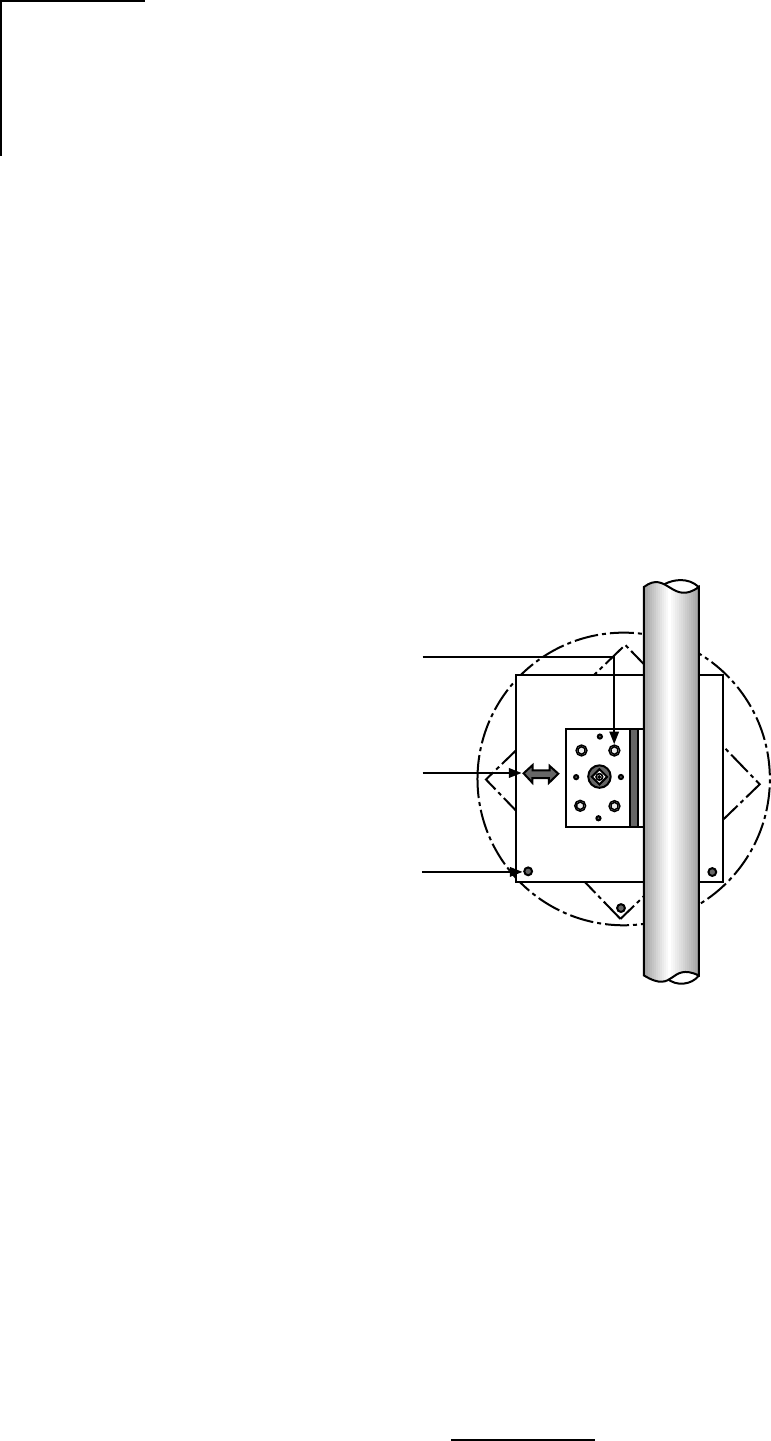
D-4
N2-X Ethernet Extender Installation and Operation Manual
Attach the antenna to the mount as shown in Figure D.4. For antenna polarization, assemble
the antenna to the mount using four sets of nuts and washers after desired polarization is
selected. In horizontal polarization the arrow sticker should be pointed in a horizontal direction.
Likewise, in vertical polarization the arrow sticker should be pointed in a vertical position.
Important: After cable connection is completed, wrap connection with Butyl or other
waterproof tape, supplied by the customer.
Each panel antenna has four factory sealed drain holes located on the back of the antenna. After
orienting the antenna to its proper polarization, the lower most sealed drain hole(s) must be
punctured with a pointed tool. See Figure D.4.
Caution: Do not allow the tool to protrude into the drain hole more than 1/4” (7mm) or damage
to the antenna may result.
Figure D.4 - Flat Panel Antenna
WL035954
Drain
Holes
Polarization
Arrow
Antenna
Polarization
using Nuts
and Washers
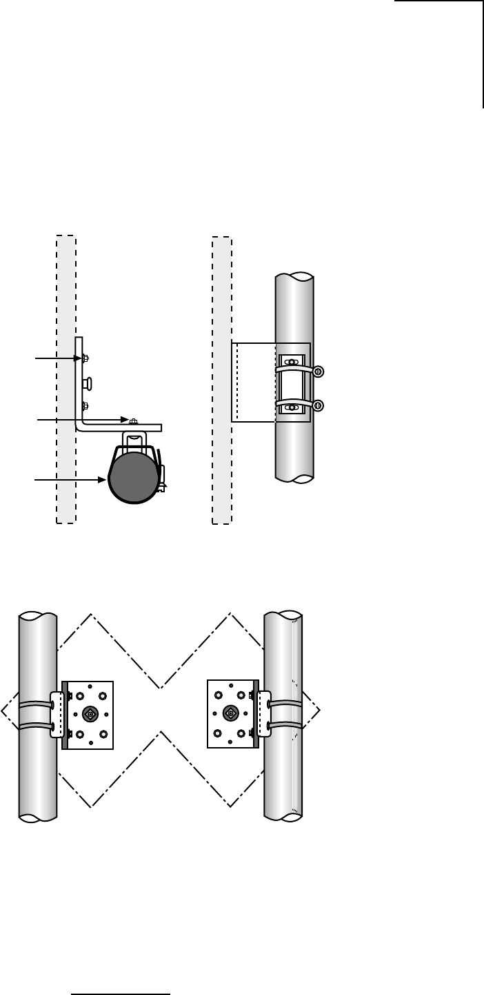
D-5
N2-X Ethernet Extender Installation and Operation Manual
Aim the antenna according to Figure D.5. Orient the antenna using instructions supplied with
the antenna. Antenna models used with this mount may be circular, square or diamond shaped.
To change the offset, unbolt the mount from the antenna, then invert the mount and reattach
in the antenna.
Figure D.5 - Adjustable Panel Antenna Mount
Rear View
Right Offset Rear View
Left Offset
Side View
Clamp Kit for
1.9 (48mm) DIA
Thru 4.5 (114mm)
DIA Masts
1/4” Carriage Bolts
w/ Washers, Lockwashers
and Nuts (2)
Elevation
Adjustment
WL035955

D-6
N2-X Ethernet Extender Installation and Operation Manual