Contents
n2xusersMANUAL

N2-X Ethernet Extender
Installation and Operations Manual
Part Number 281-104101-201
Version 0.1
February 1999
Wireless, Inc.
19 Davis Drive
Belmont, CA 94002-3001

ii
N2-X Ethernet Extender Installation and Operation Manual
Notice
Information in this document is subject to change without notice. No part of this document may
be reproduced or transmitted in any form or by any means, electronic or mechanical, for any
purpose, without the express written permission of Wireless, Inc.
© Copyright 1999, Wireless, Inc. All rights reserved.
N2-Ethernet ExtenderTM and ACCESSTM Series are trademarks of Wireless, Inc.

iii
N2-X Ethernet Extender Installation and Operation Manual
Table of Contents
1.0 General Overview ...............................................................................................................................1
1.1 N2-ACCESS Series Product Family................................................................................................1
1.2 Introduction to the N2-
X Ethernet Extender ..............................................................
1
1.3 Regulatory Information .........................................................................................................2
2.0 N2-
X Ethernet Extender
Product Profile .........................................................................................3
2.1 General Overview ..................................................................................................................3
2.2 Specifications .........................................................................................................................7
2.3 User Interfaces.....................................................................................................................12
2.4 Alarms, Indicators and Displays (Outdoor Unit) .............................................................17
2.5 Theory of Operation ............................................................................................................18
3.0 Equipment Installation and Commissioning .................................................................................21
3.1 Installation .............................................................................................................................21
3.2 Data Connectors..................................................................................................................28
3.3 Outdoor RF Unit Installation ..............................................................................................32
3.4 Commissioning ....................................................................................................................36
4.0 Maintenance and Troubleshooting ................................................................................................39
4.1 N2-
X Ethernet Extender
Maintenance .............................................................................39
4.2 Identifying and Resolving Receive Signal Strength Issues..........................................40
4.3 N2-
X Ethernet Extender
Digital Board Switch Settings ................................................42
4.4 Where to Get Further Assistance.....................................................................................47
4.5 Return Procedure ................................................................................................................48
Appendix A Network Management ..........................................................................................................A-1
Appendix B Installation Instructions ........................................................................................................B-1
Appendix C Adjustable Panel Antenna Mount .......................................................................................C-1

iv
N2-X Ethernet Extender Installation and Operation Manual
Figures
Figure 2.1 Typical Deployment of a N2-
X Ethernet Extender
in a Point-to-Point Configuration 4-5
Figure 2.2 User Interfaces........................................................................................................................12
Figure 2.3 Outdoor Unit, Interior Interfaces ...........................................................................................13
Figure 2.4 N2-
X Ethernet Extender
Bock Diagram ..............................................................................17
Figure 3.1 Power Cord Connection .........................................................................................................23
Figure 3.2a Upper Pole Mounting Bracket..............................................................................................24
Figure 3.2b Upper Pole Mounting Bracket Equipment .........................................................................24
Figure 3.2c Lower Pole Mounting Bracket ..............................................................................................25
Figure 3.2d Lower Pole Mounting Bracket Equipment .........................................................................25
Figure 3.3a V-Clamps and Hardware ......................................................................................................26
Figure 3.3b V-Clamps and Hardware (Rear View) ................................................................................26
Figure 3.4 N-Type Antenna and Ground Connections .......................................................................27
Figure 4.1 Frequency Selection for the N2-X Ethernet Extender Radio...........................................40
Figure B.1 Two Foot Diameter Antenna ...............................................................................................B-1
Figure B.2 Mount Configuration .............................................................................................................B-3
Figure B.3 Mounting Hardware Packed ................................................................................................B-5
Figure B.4 Mounting Hardware Unpacked ...........................................................................................B-5
Figure B.5 Parabolic Reflector...............................................................................................................B-8
Figure B.6 Unpacking the Radome .......................................................................................................B-8
Figure B.7 Antenna Mount Assembly ...................................................................................................B-9
Figure B.8 Antenna Mount Assembly .................................................................................................B-10
Figure B.9 Elevation Rod Assembly ....................................................................................................B-10
Figure B.10 Feed Horn Installation ........................................................................................................B-11
Figure B.11 Feed Horn Polarization Markings .....................................................................................B-12
Figure B.12 Parabola Rear View Showing Polarization Reference Markers.................................B-12
Figure B.13 Feed Horn Installation ........................................................................................................B-13
Figure B.14 Feed Horn Installation for Vertical Polarized Operation ...............................................B-13
Figure B.15 Azimuth Clamp/Shear Stop Assembly ............................................................................B-14
Figure B.16 Azimuth Adjustment Clamp Assembly .......................................................................... B-14
Figure B.17 Hoisting the Antenna ..........................................................................................................B-15
Figure B.18 Antenna Alignment using RSL Output ............................................................................B-16
Figure C.1 Antenna Mount ......................................................................................................................C-1
Figure C.2 Azimuth and Elevation Planning ........................................................................................C-2
Figure C.3 Azimuth and Elevation Planning ........................................................................................C-3
Figure C.4 Flat Panel Antenna ...............................................................................................................C-4
Figure C.5 Adjustable Panel Antenna Mount .......................................................................................C-5

v
N2-X Ethernet Extender Installation and Operation Manual
Tables
Table 1.1 FCC U-NII Bands ......................................................................................................................2
Table 3.1 Inventory of Equipment and Installation Materials ............................................................22
Table 3.2 Installation Checklist ...............................................................................................................28
Table 3.3 Approximation Table ..............................................................................................................29
Table 4.1 Frequencies.............................................................................................................................41
Table 4.2 DIP Switches ...........................................................................................................................43
Table 4.3 DIP Switches ...........................................................................................................................44
Table 4.4 Transmitter Frequency Selection.........................................................................................44
Table 4.5 DIP Switches ...........................................................................................................................45
Table 4.6 DIP Switches ...........................................................................................................................46
Table 4.7 Transmitter Frequency Selection.........................................................................................46
Table 4.8 Power Output Attenuator Selection .....................................................................................46
Table A.1 Alarm Connector Pinouts ....................................................................................................A-1
Table B.1 Two Foot Diameter Antenna Dimensions .........................................................................B-2
Table B.2a Contents List ..........................................................................................................................B-4
Table B.2b Contents List ..........................................................................................................................B-4
Table B.2c Contents List ..........................................................................................................................B-6
Table B.2d Contents List ..........................................................................................................................B-7
Table B.3 Nut Tightening Procedures ...............................................................................................B-18

vi
N2-X Ethernet Extender Installation and Operation Manual
Welcome!
Welcome to the Wireless, Inc. N2-ACCESS
TM Series product family. This manual is designed
to introduce you to the N2-
X Ethernet Extender
TM, and to provide you with information necessary
to plan, install, operate and maintain a N2-
X Ethernet Extender
wireless communication
system.
The N2-
X Ethernet Extender
is intended for professional installation only. This manual,
however, is also designed for personnel who plan, operate and administrate the N2-
X Ethernet
Extender
communication system. Please review the entire manual before powering up or
deploying any N2-
X Ethernet Extender
.
Updates to this manual will be posted on the Wireless, Inc. Customer Service Website at
http://www.wire-less-inc.com
. Registered Wireless customers can access Wireless’ on-line
information and support service, available 24 hours a day, 7 days a week. Our on-line service
provides users with a wealth of up-to-date information, with documents being added or updated
each month.
Radiation Warnings
Microwave Radio Radiation Warning
Under normal operating conditions, N2-
X Ethernet Extender
radio equipment complies with the
limits for human exposure to radio frequency (RF) fields adopted by the Federal Communica-
tions Commission (FCC). All Wireless, Inc. microwave radio equipment is designed so that
under normal working conditions, microwave radiation directly from the radio is negligible when
compared with the permissible limit of continuous daily exposure recommended in the United
States by ANSI/IEEE C95.1-1991 (R1997), Safety Levels with Respect to Human Exposure to
Radio Frequency Electromagnetic Fields, 3 kHz to 300 GHz.
Microwave signal levels that give rise to hazardous radiation levels can exist within transmitter
power amplifiers, associated RF multiplexers, and antenna systems.
Never look into the open end of a Waveguide as eyes are particularly vulnerable to radiation.
Do not disconnect RF coaxial connectors, open microwave units, or break down any
microwave screening while the radio equipment is operating.

vii
N2-X Ethernet Extender Installation and Operation Manual
Microwave Antenna Radiation Warning
Designed for point-to-point operation, an N2-
X Ethernet Extender
microwave radio system will
use directional antennas to transmit and receive microwave signals. These directional anten-
nas are usually circular or rectangular in shape, are generally located outdoors, and are usually
mounted on a tower or mast.
Referencing OET Bulletin 65 (Edition 97-01, August 1997) from the Federal Communication
Commission’s Office of Engineering & Technology, limits for maximum permissible exposure
(MPE) to microwave signals have been adopted by the FCC for both Occupational/Controlled
environments and General Population/Uncontrolled environments. These limits are 5.0 mW/
cm2 and 1.0 mW/cm 2, respectively, with averaging times of six-minutes and thirty-minutes,
respectively.
The closer you are to the front center-point of a microwave antenna, the greater the power
density of its transmitted microwave signal. Unless you are very close, however, microwave
exposure levels will fall far below the MPE limits. To determine how close to a microwave
antenna you can be and still remain below the MPE limits noted above, “worst case” predictions
of the field strength and power density levels in the vicinity of an N2-
X Ethernet Extender
TM
microwave antenna can be made from the following calculations. The equation is generally
accurate in the far-field of an antenna, and will over-predict power density in the near-field (i.e.
close to the antenna).
S = PG/4πR2
where: S = power density (in mW/cm 2)
P = power input to the antenna (mW)
G = power gain of the antenna in the direction of interest relative to an isotropic
radiator
R = distance to the center of radiation of the antenna (cm)
Note that G, the power gain factor, is usually expressed in logarithmic terms (i.e., dB), and must
be converted using the following equation:
G = 10
dB/10
For example, a logarithmic power gain of 24 dB is equal to a numeric gain of 251.19.
Assuming (1) maximum output power from the N2-
X Ethernet Extender
(+3.5 dBm [2.238 mW]),
(2) no signal loss in the cable connecting the N2-
X Ethernet Extender
to the antenna, and (3)
the use of a 27 dBi gain parabolic antenna, the 5.0 mW/cm
2 and 1.0 mW/cm 2 MPE power density
limits would be reached at distances of approximately 4.22 cm and 9.44 cm, respectively.
Wireless, Inc. fully supports the FCC’s adopted MPE limits, and recommends that personnel
maintain appropriate distances from the front of all directional microwave antennas. Should you
have questions about N2-
X Ethernet Extender
TM microwave signal radiation, please contact the
Wireless, Inc. Customer Service Department.

viii
N2-X Ethernet Extender Installation and Operation Manual
Notice Regarding Operation pursuant to FCC part 15 Rules
This equipment has been tested and found to comply with the limits for a Class A digital device
pursuant to part 15 of the FCC Rules. These limits are designed to provide reasonable
protection against harmful interference when the equipment is operated in a commercial
environment. This equipment generates, uses and can radiate radio frequency energy and, if
not installed and used in accordance with the instruction manual, may cause harmful
interference to radio communications. Operation of this equipment in a residential area is likely
to cause harmful interference in which case the user will be required to correct the interference
at his own expense.

1
N2-X Ethernet Extender Installation and Operation Manual
1.0 General Overview
1.1 N2-ACCESS Series Product Family
All N2-X Ethernet Extender radios are members of the N2-ACCESS Series radio product family.
The N2- ACCESS Series is designed to provide an economical wireless solution for local
access telecommunication requirements.
The N2-ACCESS Series radio product family consists of several product offerings, to include
both the N2-ACCESS Link. This manual addresses, in detail, the operation of the N2-X Ethernet
Extender. For detailed information on other N2-X Ethernet Extender radios or other members
of the N2-ACCESS Series, please refer to the appropriate Operation Manual(s).
1.2 Introduction to the N2-X Ethernet Extender
The N2-X Ethernet Extender series of radios are designed for operation in two of the Unlicensed
National Infrastructure at frequencies of 5,250 - 5,350 MHz or 5,725 - 5,825 MHz.
Each N2-X Ethernet Extender is comprised of a pole mounted RF/antenna unit. Each link is
powered by means of a AC wall transformer (optional DC powering available) located with the
indoor terminal unit. The system has a data transmission capacity of 16 Mb/s. Refer to the N2-
X Ethernet Extender data sheets for information relating to product offerings and specifications.

2
N2-X Ethernet Extender Installation and Operation Manual
Table 1.1 - FCC U-NII Bands
1.3 Regulatory Information
In January 1997, the FCC made available 300 MHz of spectrum for Unlicensed National
Information Infrastructure (U-NII) devices. The FCC believes that the creation of the U-NII band
will stimulate the development of new unlicensed digital products which will provide efficient and
less expensive solutions for local access applications.
The U-NII band is divided into three sub bands at 5.15 - 5.25, 5.25 - 5.35 and 5.725 - 5.825 GHz.
The first band is strictly allocated for indoor use and is consistent with the European High
Performance Local Area Network (HIPERLAN). The second and third bands are intended for
high speed digital local access products for “campus” and “short haul” microwave applications.
1dnaB2dnaB3dnaB
ycneuqerF zHG52.5ot51.5zHG53.5ot52.5zHG528.5ot527.5
)xaM(rewoP PRIEsttawillim002PRIEttaw1)PRIE(sttaw4
*
esUdednetnI ylnOesUroodnIsupmaCselim01xorppA
nodesiver)00M(redrodnanoinipomudnaromemCCFtnecerA:etoN* dnaniagiBd32htiwannetnalanoitceridafoesuehtswolla8991,42enuJ IIN-U528.5-527.5ehtnittaw1forewoptuptuorettimsnartmumixama .dnab
109530LW

3
N2-X Ethernet Extender Installation and Operation Manual
2.0 N2-X Ethernet Extender Product Profile
2.1 General Overview
The N2-X Ethernet Extender series of microwave radio products provides digital capacities for
16 Mb/s data rates for short-haul applications up to 10 km. The radio terminal operates in the
newly allocated Unlicensed National Information Infrastructure (U-NII) spectrum with a revolu-
tionary Split Modulation system architecture that provides full duplex operation in the 5.3/5.7
GHz U-NII frequency bands.
The N2-X Ethernet Extender series provides the unique advantage of a very robust digital
transmission scheme.
Split Modulation uses two separate 100 MHz bands within the U-NII frequency spectrum. Within
these bands, the N2-X Ethernet Extender series operates in one of many independent channels
providing for frequency reuse and network flexibility, ideal for dense network applications.
Synthesized RF channel selection is field configurable, as are the power output options for the
selection of antenna sizes. Frequency coordination and installation guidelines are provided in
the appendix section of this manual.
Complying with all aspects of FCC Rules Subpart 15.401-15.407, the transmission character-
istics of the N2-X Ethernet Extender series are ideally suited to meet the peak power spectral
density requirements of the U-NII 5.250 - 5.350 and 5.725 - 5.825 GHz bands.
Note: From this point on in this Operations Manual, unless specified otherwise, the term N2-
X Ethernet Extender refers to the 5.3/5.7 GHz N2-X Ethernet Extender radio.
The N2-X Ethernet Extender as been designed for complete front access to all interfaces,
controls and displays. Information in this manual will familiarize you with all of these items.
Figure 2.1 illustrates two (2) N2-X Ethernet Extender terminals in a point-to-point configuration.

4
N2-X Ethernet Extender Installation and Operation Manual
This Page Left Blank Intentionally

5
N2-X Ethernet Extender Installation and Operation Manual
Figure 2.1 Z-fold (WL035902) goes here

6
N2-X Ethernet Extender Installation and Operation Manual
Figure 2.1 Z-fold (WL035902) goes here

7
N2-X Ethernet Extender Installation and Operation Manual
2.2 Specifications
2.2.1 General
Frequency Band Full-duplex operation in both 5.2 and 5.7 GHz U-NII Bands
Regulations Complies with FCC Rules Part 15.407, U-NII
Frequency Range 5,250 - 5,350 MHz and 5,725 - 5,825 MHz
Frequency agility Tunable in 10.24 MHz steps
Low Band 5.2608 to 5.34016 GHz
High Band 5.73568 to 5.81504 GHz
Channel Pairs 8 x 16 MHz
5.2608/5.73568 GHz
5.27104/5.74592 GHz
5.28128/5.75616 GHz
5.29152/5.7664 GHz
5.30176/5.77664 GHz
5.31200/5.78688 GHz
5.32224/5.79712 GHz
5.33248/5.80736 GHz
Capacity 16 Mbps (8 Mbps when operated in half duplex Ethernet Mode)
Modulation BPSK
2.2.2 Digital Interface
Ethernet Interference

8
N2-X Ethernet Extender Installation and Operation Manual
2.2.3 Transmitter
Frequency Bands Low Band -5.250 to 5.350 GHz
High Band -5.725 to 5.825 GHz
Output Power (Max) Low Band - -1.5 or +3.5 dBm
High Band - +1.5 or +3.5 dBm
Power Spectral Density
Requirements for BW
<20 MHz Low Band -12.5 mW/MHz
High Band -50 mW/MHz
Inband Emissions Low Band -34 dB attenuation
High Band -40 dB attenuation
Out of Band Emissions Low Band -44 dB attenuation
High Band -50 dB attenuation
Frequency Tolerance ±5 ppm
2.2.4 Receiver
Type Coherent Detection
Sensitivity, BER 10 E-6 -82 dBm
Maximum Rx Input -30 dBm to meet 1 x10⁻¹⁰ BER
Without Rx Damage -0 dBm
Co-channel Interference +15 dB
Adjacent Channel
Interference (±10 MHz) +5 dB
Semi-Adjacent Channel
Interference (±20 MHz) -12 dB

9
N2-X Ethernet Extender Installation and Operation Manual
2.2.5 Antenna
General Specifications and Performance
Input RG-8 Female connector
Regulatory Compliance FCC Part 15
Frequency Range 5.2 - 5.9 GHz
E-plane Polarization ±1 deg.
2 ft. Single Polarization
Gain (mid-band) 27 dBi
Beamwidth, 3 dB 6.0 degrees
Cross Pol Disc. 28 dB
Front/Back Ratio 36 dB
VSWR 1.35:1 (RL)/16.5 dB
Mechanical/Environmental
Wind Loading EIA/TIA-195C and EIA/TIA-222E
Operational 112 km/hr (70 mph) 25 mm (1”)
Survival 201 km/hr (125 mph) 25 mm (1”)
2.2.6 Diagnostics
ODU Alarm Indicators
(for MFG and Maintenance) Normal Operation - Green LED (and no red LEDs)
Link Alarm - Red LED
Local Alarm - Red LED
Loss of Signal (LOS) - Red LED
Page Indicator - Red LED
RSSI - Red LED
ODU Performance
Monitoring RSSI - A voltage provided through a BNC connector on the
outside of the ODU. The RSSI port is used for antenna alignment
during installation and for periodic measurement of Receiver/
Path performance. The RSSI voltage is related to BER from -30
dBm to -90 dBm.
Remote Loopback - Accessed from the ODU
Local Loopback - Accessed from the ODU

10
N2-X Ethernet Extender Installation and Operation Manual
2.2.7 Power Requirements
Primary power supply
DC ±20 to ±60 V
AC 14 to 29V
103 to 127V 60 Hz with external transformer
206 to 265V 50/60 Hz with external transformer
Power Consumption Maximum 12 Watts
2.2.8 Environmental Specifications
Outdoor Unit Temperature Range -30 to +55°C
Altitude -4,500 meters max
Humidity - Outdoor, all-weather enclosure
2.2.9 Mechanical
Dimensions (HxWxD) 356 x 203 x 76 mm
Weight 3.5 kg
11
N2-X Ethernet Extender Installation and Operation Manual
2.3 User Interfaces
The N2-X Ethernet Extender provides user interfaces for fused DC power connection, electrical
grounding, radio frequency (RF) antenna connection, digital signal input/output, radio configu-
ration and status, andRSSI output. The following provides information on each interface.
Outdoor Unit
•Cable 1 - Ethernet Signal cable
•Cable 2 - Power cable
•AGC (RSSI) - BNC type connector used for RSSI measurement.
•Antenna (RF) Connector - N-type connector used for connection with antenna.
•Ground - A Ground point for outdoor unit housing.
•Main Power - The N2-X Ethernet Extender is designed to work from a power input of 15
VDC provided by a wall type power supply operating from an AC outlet capable of providing
100 - 240 VAC. As an option, the Interface Unit can be powered by means of a DC source.
The power connector is industry-standard.
•Grounding Connector - The front panel of the N2-X Ethernet Extender is equipped with
an M5 ground screw and associated washers. This ground screw serves as the proper
chassis-ground connection point for an external ground source. The N2-X Ethernet
Extender must be grounded in accordance with the electrical codes, standards, and
practices governing the local installation.
Refer to Figure 2.2 and 2.3.
12
N2-X Ethernet Extender Installation and Operation Manual
Figure 2.2 - Outdoor Unit, Exterior
Female N Type
Connector
Female BNC
Connector
Chassis Grounding
Terminal
Condensation
Valve
Strain Relief Waterproof
Cable Entries
WL035903
13
N2-X Ethernet Extender Installation and Operation Manual
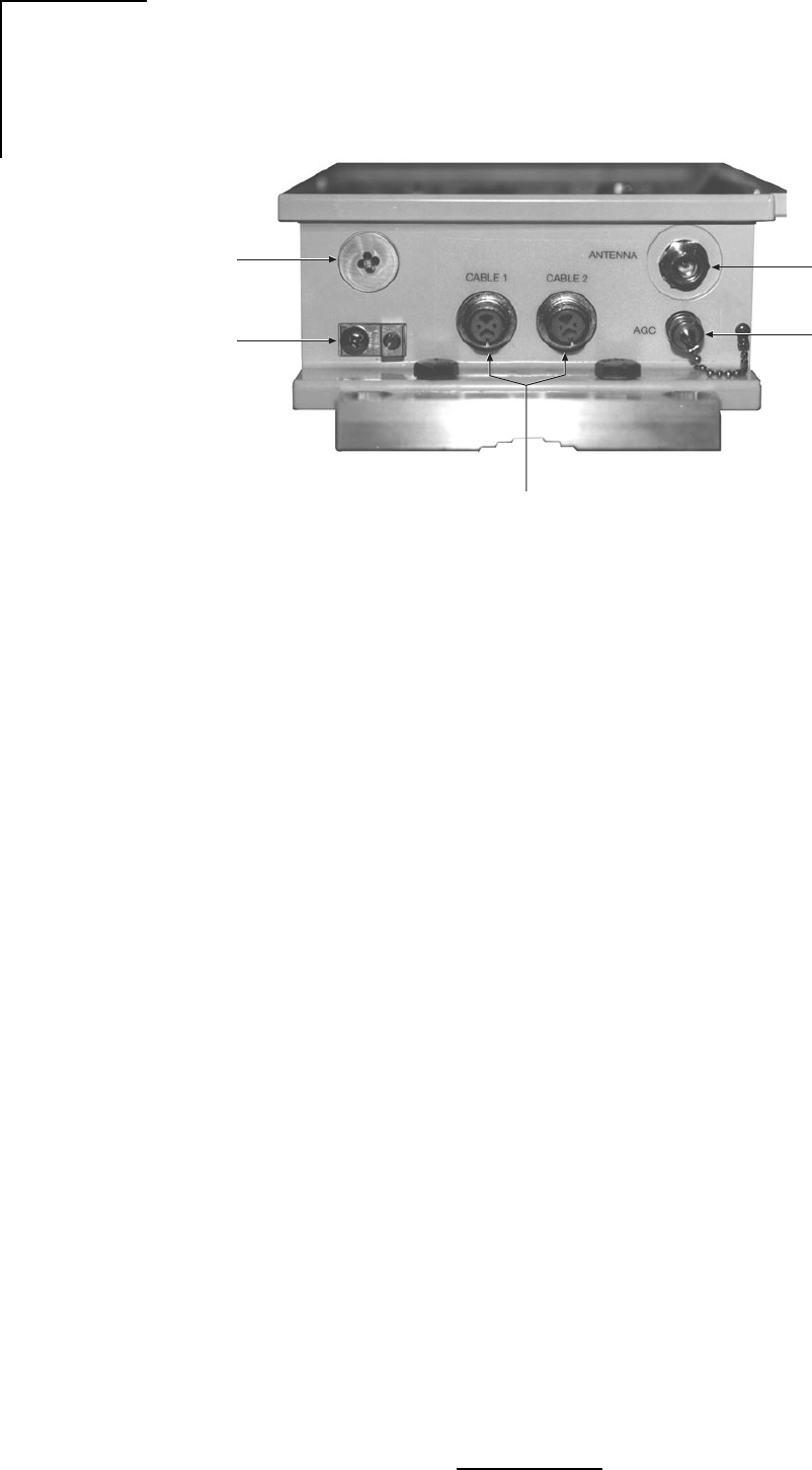
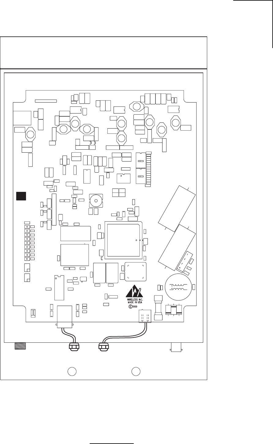
Figure 2.3 - Outdoor Unit, Interior Interfaces
WL035904
Antenna Cable 1 Cable 2 BNC

14
N2-X Ethernet Extender Installation and Operation Manual
2.4 Alarms and Indicators (Terminal Unit)
The N2-X Ethernet Extender Terminal Unit is equipped with diagnostic tools in the form of LED
indicators. The following describes the functions of these items as shown in Figure 2.2.
2.4.1 Power LED
The Power LED:
•Green - The N2-X Ethernet Extender has proper DC power applied, and the unit is On.
•Clear/Off - The N2-X Ethernet Extender is Off or has no DC power supplied.
2.4.2 Local Alarm LED
The Local Alarm LED is a single-color (red) device:
•Red - The N2-X Ethernet Extender is registering one or more monitored alarm functions:
summary radio alarm, loss of local data input, bipolar violations (BPV) detected on local
incoming data, or power supply failure.
•Clear/Off - The N2-X Ethernet Extender is not registering any alarm condition.
2.4.3 Link Alarm LED
The Link Alarm LED is a single-color (red) device:
•Red - A loss of data signal from the far terminal has occurred.

15
N2-X Ethernet Extender Installation and Operation Manual
2.5 Alarms, Indicators and Displays (Outdoor Unit)
The N2-X Ethernet Extender outdoor RF unit is provided with several LED indicators that supply
operational status. Figure 2.4 shows the location of each indicator.
2.5.1 ODU Alarm Indicators
• Normal Operation (Green LED) -
• Page 0 (Red LED) - When On (red), indicates that page 0 of the EEPROM has loaded to
the FPGA indicating that a reset or start condition has occurred.
• Link Alarm (Red LED) - Indicates that the data signal from the far end terminal is not
present.
• Local Alarm (Red LED) - An alarm condition is present at the local terminal.
• Loss of Signal (LOS) Alarm (Red LED) - The signal from the far end terminal has dropped
below threshold.
• DRSSI Alarm (Red LED) -
2.5.2 ODU Performance Monitoring
RSSI - A voltage provided through a BNC connector on the outside of the ODU. The RSSI port
is used for antenna alignment during installation and for periodic measurement of
Receiver/Path performance. The RSSI voltage is related to Rx BER from -30 dBm to -90
dBm.
Remote Loopback - Accessed from the ODU
Local Loopback - Accessed from the ODU
ODU Alarm Indicators
ODU Performance monitoring

16
N2-X Ethernet Extender Installation and Operation Manual
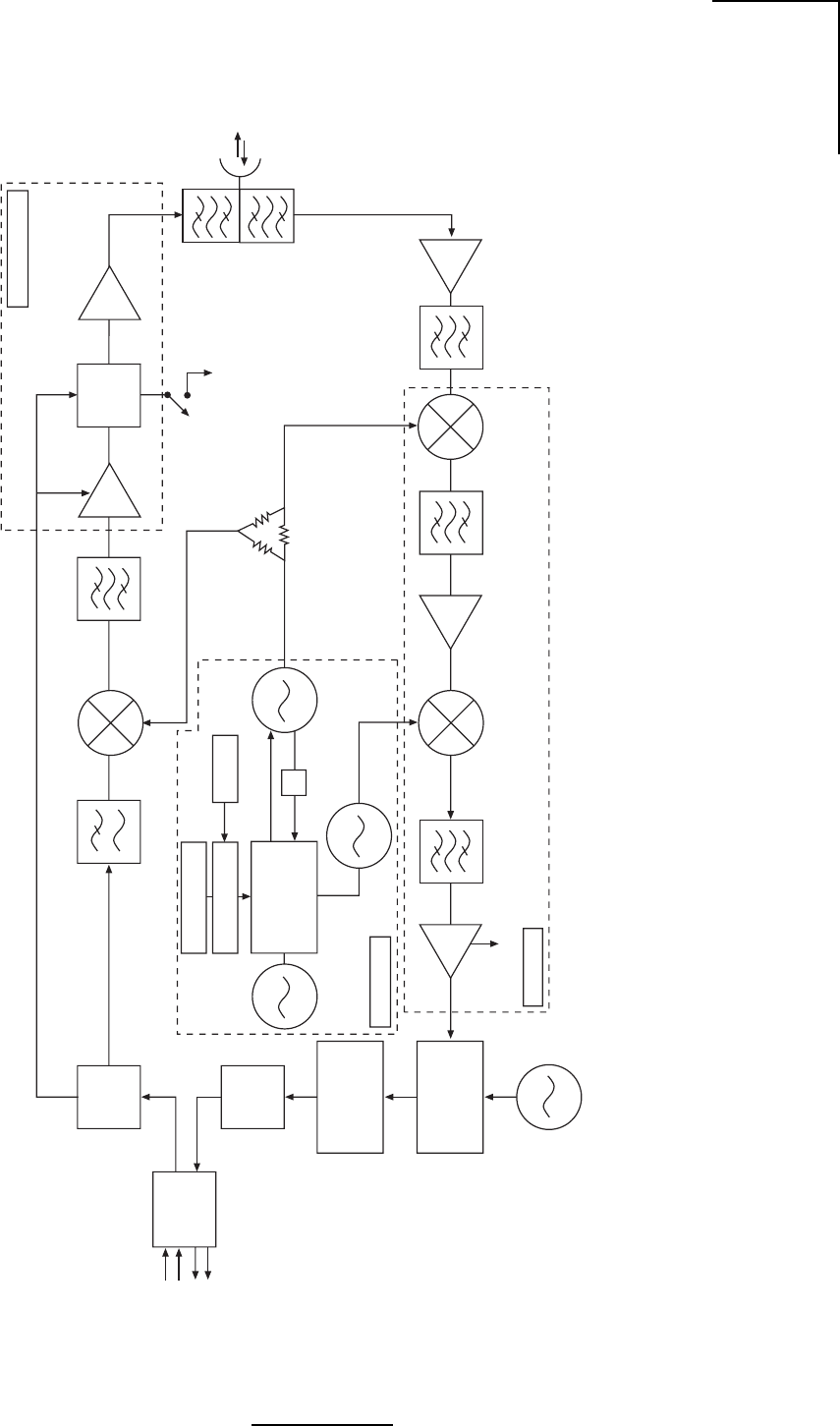
2.6 Theory of Operation
2.6.1 N2-X Ethernet Extender Transmitter
This description should be used in conjunction with the system block diagram Figure 2.4.
The data signal and the AC/DC supply voltage are connected to the ODU by means of a
power/data cable assembly. The supply voltage passes through a bridge rectifier to a DC
to DC converter. The output of this converter is +15V. This +15V supply drives three DC
regulators within the ODU.
One regulator provides -5 VDC, the second 11 VDC and the third being a dual output type
supplies +5 and +5.8 volts.
The FPGA coder interleaves and scrambles the TTL data from the coder. The FPGA is
programmed to output the data at 4 times the input rate (6.176 MHz for the DS1 rate or
8.192 MHz for E1 rates). This provides a data rate which is optimal with respect to the FCC
rules for spectral power densities defined for this frequency allocation.
The data is passed through a 7th order low pass filter to reduce unwanted high frequency
signal images prior to modulation. A double balanced mixer is used to modulate the data
signal on to a CW signal provided by the synthesizer at the desired output frequency. The
output of the mixer contains the BPSK modulated signal at the desired frequency.
A high pass filter eliminates spurious noise, rejects harmonic images and insures that the
proper bandwidth is maintained prior to being amplified.
The RF output section consists of three main components: a RF driver amplifier, a logic
controlled switch attenuator and a RF power amplifier. The driver amplifier provides the first
stage of RF amplification, the switch attenuator serves a dual purpose. The first is to
provide a customer selectable 6 dB attenuator to reduce output power when needed.
Secondly, this circuit acts as an RF impedance matching network between the driver and
power amplifier gain stages. The power amplifier provides the amplification required prior
to being output through a diplexing filter and ultimately to the antenna.
17
N2-X Ethernet Extender Installation and Operation Manual
Figure 2.4 -
N2-X Ethernet Extender
Block Diagram
FPGA
Coder
Clock/Data
De-
Coder
-6.176 to -8.192
Bit
Synchronizer
BPSK
Demodulator
85.12 MHz
6.176 Mb/s for T1
8.192 Mb/s for E1
Data Input
Level
Converter
Data Output
RSSI 85.12 MHz
Dual
Synthesizer
Low Pass
Filter
BPSK Modulator
High Pass
Filter Driver
Power Control
Loader
DIP Switch
PROM
Switch
Attn.
Power Amplifier
TX
RX
Parabolic
Antenna
2nd
Down
Converter
474.880 MHz
MMIC
AMP 1st
Down
Converter
Low
Noise
Amplifier
Diplexer
-6 dB
5.3/5.7 GHz
389.76 MHz
WL035905
19.2 MHz
TcXo
TTL
TTL
I & Q
÷2
IF Section
RF Amplification
Synthesizer

18
N2-X Ethernet Extender Installation and Operation Manual
2.6.2 N2-X Ethernet Extender Receiver
The description should be used in conjunction with the system block diagram (Figure 2.4).
At the antenna, the received BPSK modulated signal from the opposite terminal is passed
through a diplexing filter which is used to isolate the incoming signal from the transmitter output
and to bandpass filter the received signal thereby reducing the chance of unwanted signal
products from entering the receiver. A low noise amplifier (LNA) detects and amplifies the signal
bandpass filter on the output of the LNA provides band limiting of the received spectrum to reject
unwanted signal products. The first downconverter combines a CW signal at the receiver
frequency from the synthesizer and the incoming signal by means of a mixer to produce the first
IF product at 474.880 MHz. A 75 MHz bandpass filter limits the possibility of unwanted out of
band products from entering the 2nd IF. The first IF is amplified by a MMIC device and is
downconverted by mixer a 389.76 MHz signal from the synthesizer with the 474.880 MHz 1st
IF signal. The result is a 85.12 MHz 2nd IF product which is bandpass filtered and fed to an RSSI
IF processing DC which derives an RSSI voltage used to determine signal strength.
A BPSK demodulator places the 85.12 MHz 2nd IF and 85.12 MHz varactor diode source out
of phase. The resultant product is a DC level I and Q signal of which only the I signal is input
to the Bit Synchronizer to re-clock the data. The re-clocked data is decoded and output at TTL
level to the DS1/E1 level converter which outputs the data in AMI, B8ZS or HDB3 format as
needed. The data is interconnected to the TU and output on the front panel by means of RJ-
48C or BNC connector depending on the data format being used.
2.6.3 Synthesizer
The FPGA provides four 22-bit streams in a serial format loaded to the synthesizer. This data
provides all of the possible frequencies at which the system can operate. Depending upon the
dip switch settings selected, the actual frequency being used is selected. When the reset button
is pressed, the FPGA will reload this data to the synthesizer. The PROM contains all of the
possible frequency combinations.

19
N2-X Ethernet Extender Installation and Operation Manual
3.0 Equipment Installation and Commissioning
3.1 Installation
The N2-X Ethernet Extender has been specifically designed for ease of installation. The
following installation instructions should be followed.
1. Plan the installation - Decide where each component of the N2-X Ethernet Extender will
be placed prior to commencement of any installation activity. Installation considerations for
each component in general are as follows:
a. Outdoor RF Unit - Mount as close as practical to the Antenna assembly. The maximum
distance is determined by the included interconnect cable which is 1 meter in length.
Determine pole mounting details for the Outdoor Unit and Antenna. Adjust output power
according to section 4.2.1.
b. Antenna Unit - See Appendix B.
2. Inventory your equipment and installation materials.
To install one (1) terminal you should have the items shown in Table 3.1.
3. The following tools should be on hand:
Tool Purpose
Wire Stripper/Cutter General wire stripping and cutting purposes
Hand-Held Voltmeter (VOM) Confirm magnitude, polarity, continuity
with standard probes
2 Adjustable Wrenches Antenna mounting, Outdoor Unit up to 1.5 cm
Flat Screwdriver Outdoor Unit Grounding

20
N2-X Ethernet Extender Installation and Operation Manual
Table 3.1 - Inventory of Equipment and Installation Materials
metIrebmuNtraPnoitpircseDytQ
*a1101-910011-152etar1SDzHG053.5-052.5tinUroodtuO1
*b1102-910011-152mhO57etar1EzHG053.5-052.5tinUroodtuO1
*c1103-910011-152mhO021etar1EzHG053.5-052.5tinUroodtuO1
*d1301-910011-152etar1SDzHG528.5-527.5tinUroodtuO1
*e1302-910011-152mhO57etar1EzHG528.5-527.5tinUroodtuO1
*f1303-910011-152mhO021etar1EzHG528.5-527.5tinUroodtuO1
2)CxidneppAees(ylbmessAannetnA1
3elbaCannetnA-UDO1
4520-014303-500SS,dHxeH,mm52x01M,wercS4
5021-014303-500SS,dHxeH,mm021x01M,wercS4
6100-014013-500SS,01MtalF,rehsaW4
7100-014113-500SS,kcoLtilpS01M,rehsaW4
8100-014023-500SS,xeH,01M,tuN4
9100-800093-700”23/3x”2/1x”01,xaoC,laeS3
01100-820001-800mottoB,retpadAtnuoMeloP1
11100-920001-800poT,retpadAtnuoMeloP1
21100-030001-800pmalC,retpadAtnuoMeloP2
31100-100014-019V022/011CD/CA,retrevnoC1
.ylbmessalanimretrepderiuqereno:etoN* 609530LW
21
N2-X Ethernet Extender Installation and Operation Manual
3.2 Ethernet Data Connectors
The Ethernet connections are made to the data side of the power/data cable assembly, normally
it is supplied with an RJ48 connector.
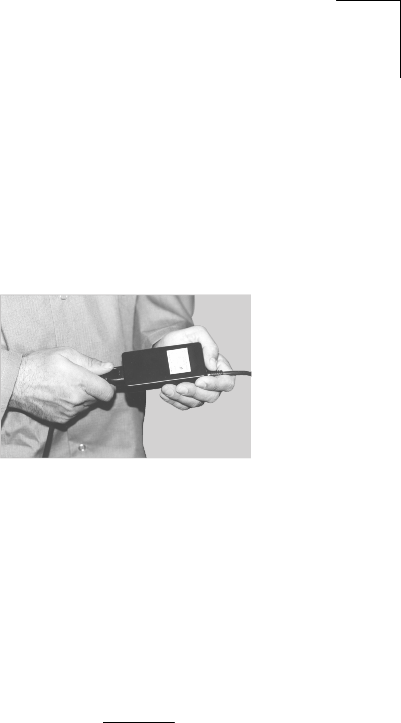
3.3 Connect the Wall Transformer to the Terminal Unit
The AC wall transformer is connected to an AC outlet by means of an IEC type power cord.
Connect the power cord to the transformer as shown in Figure 3.1.
Figure 3.1- Power Cord Connection
WL035907
22
N2-X Ethernet Extender Installation and Operation Manual
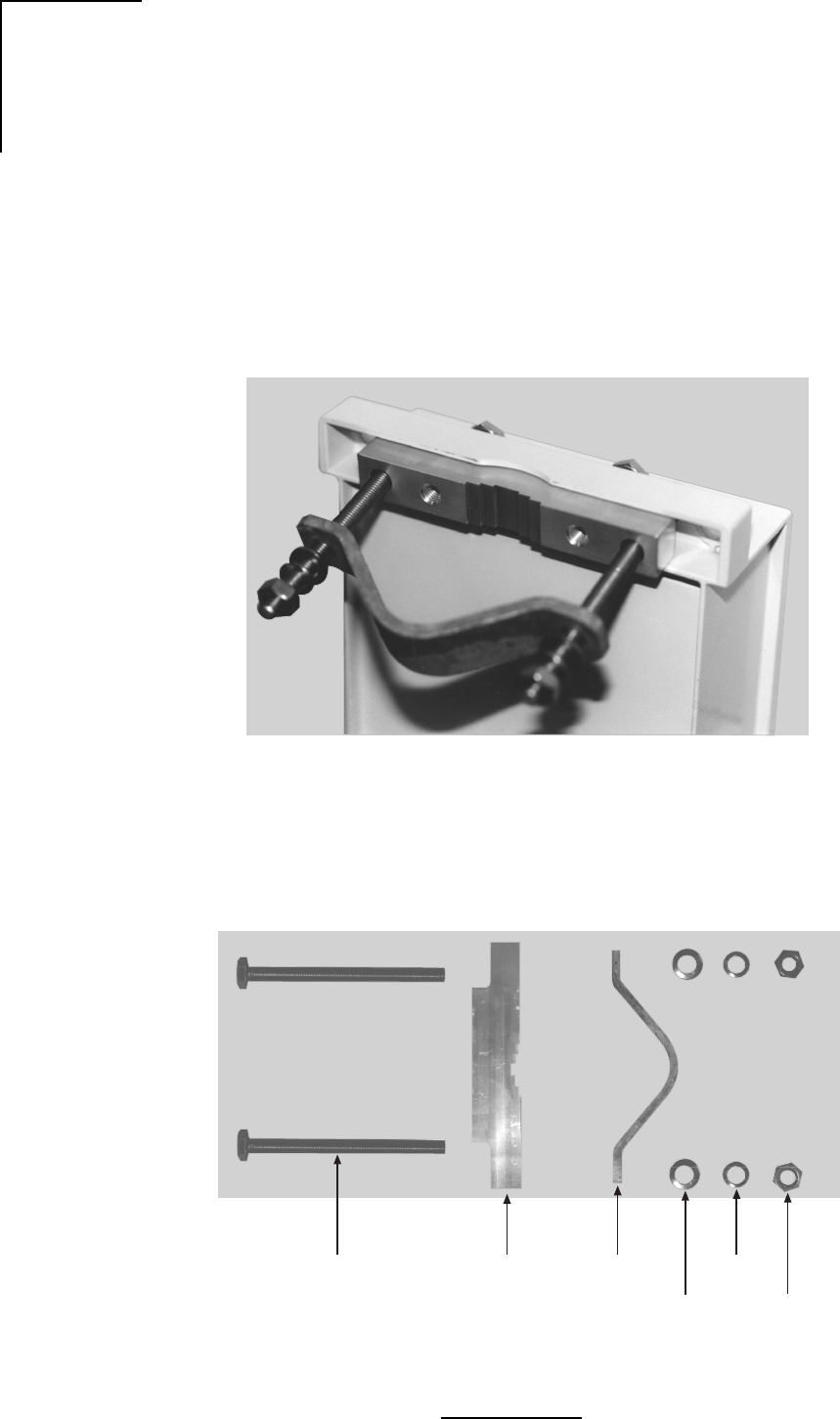
3.4 Outdoor RF Unit Installation
1. Install the upper and lower outdoor unit pole mount adaptor brackets. Figures 3.2a through
3.2d show the upper and lower mounting brackets installed and the equipment involved.
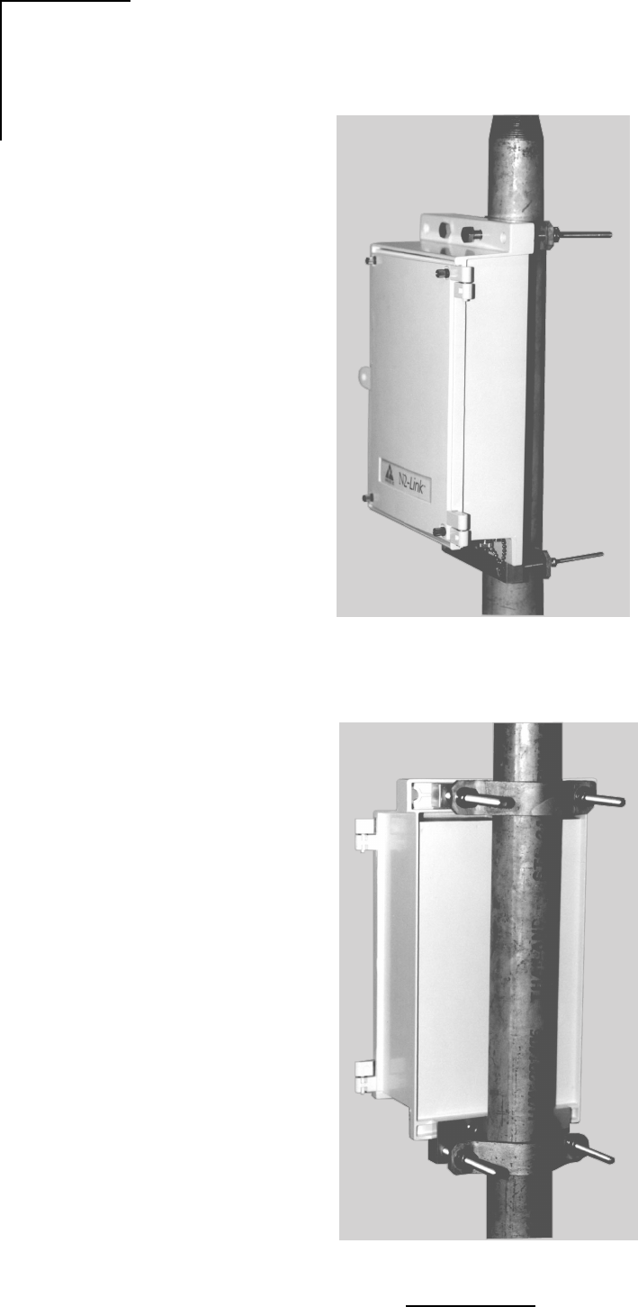
2. Place the outdoor unit against the pole mole and attach to the pole using the V-clamps and
hardware as shown in Figures 3.3a and 3.3b.
3. Connect the twin-axial, N-type antenna and ground connections as shown in Figure 3.4.
Figure 3.2a - Upper Pole Mounting Bracket
Figure 3.2b - Upper Pole Mounting Bracket Equipment
WL035908
Flat
Washer
Lock
Washer
Nut
RF Encloser
Attachment
Bracket
Pole Mount
V-Clamp
Bolt
WL035909
23
N2-X Ethernet Extender Installation and Operation Manual
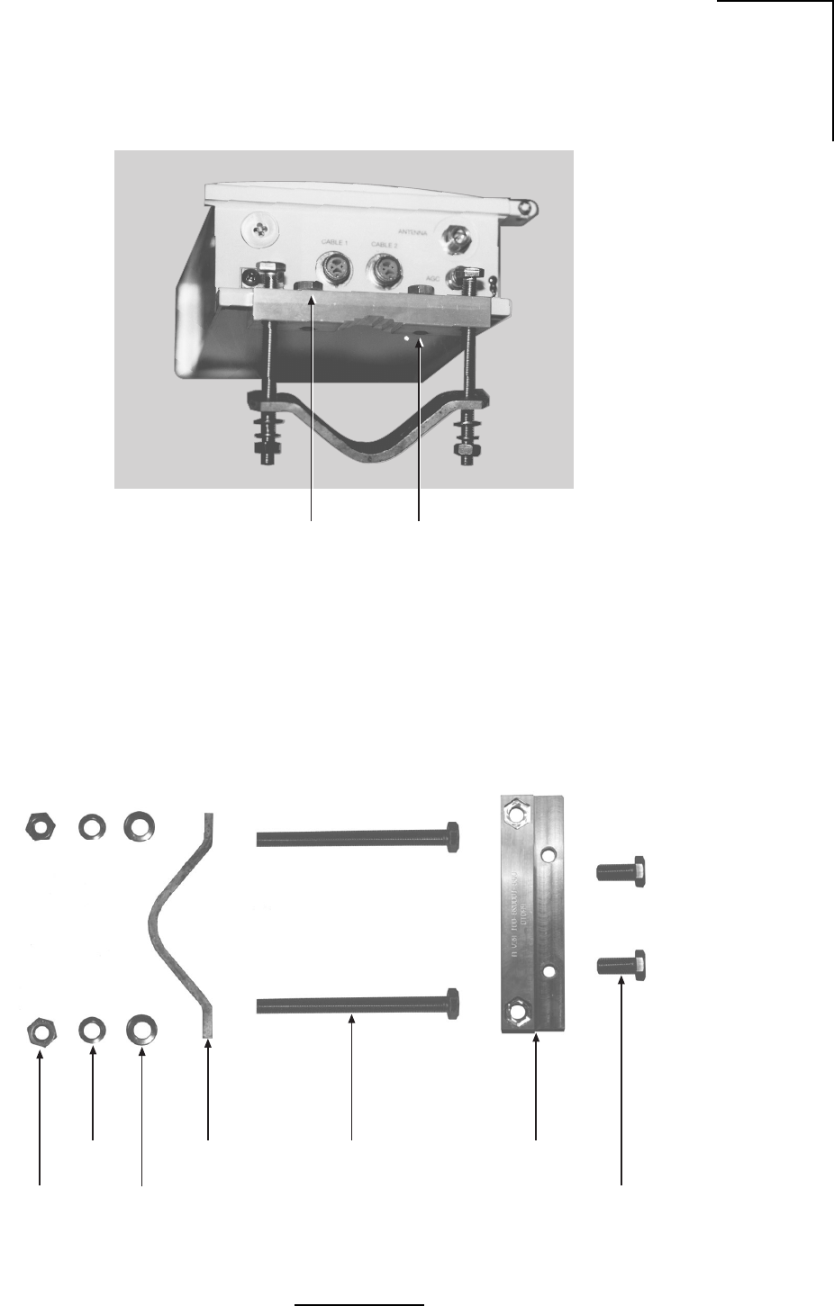
Figure 3.2c - Lower Pole Mounting Bracket
Figure 3.2d - Lower Pole Mounting Bracket Equipment
Nut, M10,
Hex, SS
Washer,
Lock #5MM SS
Washer,
Flat #5 SS
Pole Mount
Adapter, Clamp Bolt, M10 x 120MM,
HEXHD, SS Pole Mount
Adapter, Top
Bolt, M10 x 25MM,
HEXHD, SS
WL035911
Bracket Securing
Bolt (2) Lower Pole
Mounting
WL035910
24
N2-X Ethernet Extender Installation and Operation Manual
Figure 3.3a - V-Clamps and Hardware
Figure 3.3b - V-Clamps and Hardware (Rear View)
WL035912
WL035913

25
N2-X Ethernet Extender Installation and Operation Manual
Figure 3.4 - N-Type Antenna and Ground Connections
WL035914
Ground
Power and
Ethernet Cables
N-Type Antenna
Connector

26
N2-X Ethernet Extender Installation and Operation Manual
3.5 Commissioning
1. Visually verify that the N2-X Ethernet Extender is properly mounted.
2. Verify that the AC power input to the N2-X Ethernet Extender wall transformer is on.
3. Verify that the Power LED is On. If the LED is Off, refer to the Maintenance and
Troubleshooting section of the manual.
Refer to Table 3.2.
3.5.1 Configuring N2-X Ethernet Extender System Antennas
The antennas used on an N2-X Ethernet Extender radio system are generally configurable for
either vertical or horizontal polarization. It is extremely important to verify that both antennas
are configured for the same polarization, and that the appropriate antenna polarization has
been selected for the specific radio link.
Table 3.2 - Installation Checklist
tsilkcehCnoitallatsnI
?eruceserawdrahgnitnuomkcarehtsI
?dednuorgylreporptinuehtsI
?detcennocylreporpannetnaehtsI
?tcerrocdnaecalpnisnoitcennocatadehterA
?nODELrewoPehtsI
519530LW

27
N2-X Ethernet Extender Installation and Operation Manual
3.5.2 Aligning the N2-X Ethernet Extender System Antennas
With the N2-X Ethernet Extender at each site properly configured for operation, antenna
alignment must be performed at both sites. Proper antenna alignment is crucial to the proper
operation of an N2-X Ethernet Extender radio system, and should only be accomplished by
experienced professionals.
The N2-X Ethernet Extender is equipped with a ODU mounted BNC-(f) Link Test connector to
which an analog or digital voltmeter can be connected. The voltage range at the test point,
between the center conductor of the connector and ground, varies from approximately two VDC
to four VDC, serving as a receive signal strength indicator (RSSI). The stronger the receive
signal, the higher the RSSI voltage.
Emanating from a microwave antenna is a main beam (or lobe) of RF energy, surrounded by
RF side lobes. The beamwidth of the main beam varies with the size and type of antenna, as
well as the specific frequency of the RF signal, and is generally defined by the nominal total width
of the main beam at the half-power (-3 dB) points. Side lobes surround the main beam at specific
angle distances, and will be lower in power than the main beam.
When aligning an antenna system, it is extremely important to verify that the antennas are both
aligned on the main beam, not on a side lobe. Referencing Table 3.3, the first side lobe will
generally be located at an angle slightly less than twice the antenna beamwidth.
Following the course alignment of an antenna system, a common practice when performing a
fine alignment is to slowly swing each antenna (one at a time!) in both vertical (elevation) and
horizontal (azimuth) planes to verify that the main beam and first side lobe can be accurately
identified. This insures that accurate alignment of the antenna system on the main beam has
been accomplished.
Each N2-X Ethernet Extender is shipped with an RSSI test sheet, showing the relationship
between the receive signal strength level (in dBm) and the RSSI level (in VDC). These RSSI
test sheets are often referred to as AGC Curves. The RSSI test sheets can be used to verify
that the calculated receive signal levels match up with the actual receive signal levels.
Substantial differences between calculated and actual levels could point to transmission
system problems, side lobe alignment, path obstructions, etc.
Table 3.3 - Approximation Table
retemaiDannetnA elytSdna )iBd(niaG htdiwmaeBBd3 )seerged(
,eboLediSts1 mumixaM )seerged(
,eboLediSdn2 mumixaM )seerged(
cilobaraptoof-2
cilobaraptoof-4
619530LW

28
N2-X Ethernet Extender Installation and Operation Manual

29
N2-X Ethermet Extender Installation and Operation Manual
4.0 Maintenance and Troubleshooting
The N2-X Ethernet Extender contains static sensitive components, and has no user-service-
able parts.
4.1 N2-X Ethernet Extender Maintenance
The N2-X Ethernet Extender is designed to operate with no scheduled maintenance activities.
From a precautionary perspective, a regular check of power supply input voltages and RSSI
voltages should be planned by the user.
4.1.1 RSSI Voltage
The Wireless Customer Service department recommends a monthly check of the N2-X
Ethernet Extender’s RSSI voltage. Variations in the RSSI voltage could be an indicator of
antenna or antenna feed movement, loose or improper RF cabling or connectorization, path
obstructions or reflections, etc.

30
N2-X Ethernet Extender Installation and Operation Manual
4.2 Identifying and Resolving Receive Signal Strength Issues
There are a great number of items which can affect the transmission of a microwave signal from
one site to another. Every microwave path is unique, and must be evaluated for performance
before a radio link is installed.
Outside of radio equipment issues, antenna alignment, RF signal blockage, and multipath
fading are among the most common transmission problems experienced in the field.
4.2.1 N2-X Ethernet Extender Equipment Issues
Frequency Selection
1. Verify the transmit/receive frequency selection for each N2-X Ethernet Extender radio is
set appropriately, and that a “matched pair” of radios has been selected for the system.
Each N2-X Ethernet Extender terminal can be set to the frequencies listed in Table 4.1.
2. To reduce the possibility of co -adjacent channel interference, proper frequency coordi-
nation and antenna polarization is used to isolate each channel. The concept is to achieve
maximum RF isolation between link channels by means of frequency spacing and antenna
polarization. In a “star” configuration an optimum frequency and antenna polarization plan
is provided to demonstrate an example of maximum isolation between links (See Figure
4.1).
Figure 4.1 - Frequency Selection for the N2-X Ethernet Extender Radio
1H 1
2H
2
4H
4
3H
3
7V
7
8V
8
6V
6
5V
5
H = Horizontal Antenna Polarization
V = Vertical Antenna Polarization
WL035917
H
H
H
H
VV
V
V

31
N2-X Ethermet Extender Installation and Operation Manual
Table 4.1 - Frequencies
.oNlennahCycneuqerF
18062.5
'1865337.5
240172.5
'229547.5
382182.5
'361657.5
425192.5
'44667.5
567103.5
'546677.5
600213.5
'688687.5
742223.5
'721797.5
884233.5
'863708.5
819530LW

32
N2-X Ethernet Extender Installation and Operation Manual
4.3 N2-X Ethernet Extender Digital Board Switch Settings
There are two versions of the N2-X Ethernet Extender Digital Board. Before making switch
changes, verify the version of the Digital Board in use. In a working system, the East Radio might
be equipped with Version one while the West Radio might be equipped with Version two. The
specific version of a N2-X Ethernet Extender’s Digital Board will have no effect on the operation
of a radio system.
In addition to there being two versions of the Digital Board, there are also two types of Digital
Boards: a X Mb/s type and a X Mb/s type. Each type of Digital Board contains different
components.
4.3.1 Digital Board Version One
This Board does not have a white silkscreen of the Wireless, Inc. logo above the board number
designation 019-XXXXXX-001. It is equipped with three switches:
1. A Red 8-position DIP switch, right-angle, located in the middle of the Board.
2. A small, tow-position switch, located just to the left of the Red 8-position DIP switch.
3. A Black 8-position DIP switch, located at the bottom of the Board, labeled S2.

33
N2-X Ethermet Extender Installation and Operation Manual
Red 8-position DIP Switch, Right Angle
The switch positions are read from left to right. On=Up and Off=Down. See Table 4.2.
Table 4.2 - DIP Switches
1-WS
2-WS
3-WSnOsyawlA-ylnOesUyrotcaF
4-WSnOsyawlA-ylnOesUyrotcaF
5-WSnOsyawlA-ylnOesUyrotcaF
6-WS
7-WS
8-WS
919530LW

34
N2-X Ethernet Extender Installation and Operation Manual
Small, 2-Position Switch, Power Output Attenuator
On = Toward edge of board. Off = Toward Center of Board. When the 6 dB Attenuator is on,
transmitter output power will drop by 6 dB. On= 6 dB Power Output Attenuator is On (Lowers
output power by 6 dB). Off = 6 dB Power Output Attenuator is Off.
Black 8-Position DIP Switch (“S2”)
The switch positions are read from left to right. On= Up and Off = Down. See Tables 4.3 and
4.4.
Table 4.3 - DIP Switches
Table 4.4 - Transmitter Frequency Selection
lennahC)zHG(woLxT)zHG(hgiHxT1-WS2-WS3-WS4-WS5-WS
108062.586737.5nOnOnOnOnO
240172.529547.5nOnOffOnOnO
382182.561657.5nOnOnOffOnO
425192.504667.5nOnOffOffOnO
567103.546677.5nOnOnOnOffO
600213.588687.5nOnOffOnOffO
742223.521797.5nOnOnOffOffO
884233.563708.5nOnOffOffOffO
129530LW
1-WSnoitceleSycneuqerF
2-WSnoitceleSycneuqerF
3-WSnoitceleSycneuqerF
4-WSnoitceleSycneuqerF
5-WSnoitceleSycneuqerF
6-WSffOsyawlA-ylnOesUyrotcaF
7-WSffOsyawlA-ylnOesUyrotcaF
8-WSffOsyawlA-ylnOesUyrotcaF
029530LW

35
N2-X Ethermet Extender Installation and Operation Manual
4.3.2 Digital Board Version Two
This Board does have a white silkscreen of the Wireless, Inc. logo above the board number
designation 019-XXXXXX-001. The logo will be similar to the one on the cover of this manual.
This Board is equipped with two switches:
1. S black 8-position DIP switch, located in the middle of the Board, labeled S3.
2. A black 10-position DIP switch, located at the bottom of the Board, labeled S2.
Black 8-Position DIP Switch (“S3”)
The switch positions are read from left to right. On = Up and Off = Down. See Table 4.5.
Table 4.5 - DIP Switches
1-WS
2-WS
3-WSnOsyawlA-ylnOesUyrotcaF
4-WSnOsyawlA-ylnOesUyrotcaF
5-WSnOsyawlA-ylnOesUyrotcaF
6-WS
7-WS
8-WS
919530LW

36
N2-X Ethernet Extender Installation and Operation Manual
Black 1-Position DIP Switch (“S2”)
The switch positions are read from left to right. On = Up and Off = Down. When the 6 dB is on,
transmitter output power will drop by 6 dB. See Tables 4.6 through 4.8.
Table 4.6 - DIP Switches
Table 4.7 - Transmitter Frequency Selection
Table 4.8 - Power Output Attenuator Selection
1-WSnoitceleSycneuqerF
2-WSnoitceleSycneuqerF
3-WSnoitceleSycneuqerF
4-WSnoitceleSycneuqerF
5-WSnoitceleSycneuqerF
6-WSffOsyawlA-ylnOesUyrotcaF
7-WSffOsyawlA-ylnOesUyrotcaF
8-WSffOsyawlA-ylnOesUyrotcaF
9-WSffOsyawlA-ylnOesUyrotcaF
01-WSrotaunettAtuptuOrewoP
329530LW
lennahC)zHG(woLxT)zHG(hgiHxT1-WS2-WS3-WS4-WS5-WS
108062.586737.5nOnOnOnOnO
240172.529547.5nOnOffOnOnO
382182.561657.5nOnOnOffOnO
425192.504667.5nOnOffOffOnO
567103.546677.5nOnOnOnOffO
600213.588687.5nOnOffOnOffO
742223.521797.5nOnOnOffOffO
884233.563708.5nOnOffOffOffO
129530LW
rotaunettABd601-WS
nOffO
ffOnO
529530LW

37
N2-X Ethermet Extender Installation and Operation Manual
4.4 Where To Get Further Assistance
Your primary source of assistance is the support staff of the organization from which you
purchased this product. The Wireless, Inc. support staff should only be contacted directly if you
purchased this product directly from Wireless, Inc., or if you are unable to obtain sufficient
assistance from your primary support contact.
General Product and Company Information
Wireless, Inc.
19 Davis Drive
Belmont, CA 94002-3001
USA
Tel.: +650 595 3300
Fax: +650 595 4907
E-mail: info@wire-less-inc.com
Website: www.wire-less-inc.com
Detailed Product Information, Sales/Pricing Information and Pre-Sales Technical
Support
Wireless, Inc.
Sales Department
19 Davis Drive
Belmont, CA 94002-3001
USA
Tel: +650 595 3300
Fax: +650 595 2417
E-mail: sales@wire-less-inc.com
Website: www.wire-less-inc.com
Post-Sales Technical Support (Customer Service)
To assist you with field issues and, if necessary, to arrange for repair services, Wireless, Inc.'s
Customer Service department can be reached via telephone, facsimile, e-mail, mail, or through
our Website.

38
N2-X Ethernet Extender Installation and Operation Manual
4.5 Return Procedure
All material returned to Wireless, Inc. must be accompanied by a Return Material Authorization
(RMA) number from Wireless, Inc.'s Customer Service department. If you purchased your
Wireless, Inc. product through a distributor, the Wireless RMA number should be obtained
through the distributor. An RMA number is necessary to assure proper tracking and handling
of returned material at the factory. Wireless, Inc. reserves the right to refuse shipments not
accompanied by an RMA number. Refused shipments will be returned to the shipper via collect
freight.
To obtain an RMA number, contact Wireless, Inc. as follows:
Telephone: +650 595 3300
Fax: +650 595 4907
E-mail: customerservice@wire-less-inc.com
The following information will be required to issue an RMA number:
• Part Number
• Serial Number
• Failure Description
• Contact person, telephone, and fax numbers
• Ship-to address
• Bill-to address*
• Customer purchase order* (P.O.) or reference number
* Required for non-warranty repair services. For non-warranty repair services, an RMA
number will be issued when Wireless, Inc. acknowledges the purchase order.
Important - All non-U.S. returns must include 5 copies of proforma/customs invoice for each
shipment which lists:
• RMA number
• Value of items
• Description of items (including the Wireless model or part number)
Please send all returns to:
Wireless, Inc.
Attn: RMA Department
19 Davis Drive
Belmont, CA 94002-3001
USA
RMA No. __________
The customer is responsible to properly label and package repairs and prepay shipping to
Wireless, Inc. If possible, the original packaging material should be used to return electronic
parts. The RMA number must be visible on the outside of all packages returned. Unless other
arrangements have been made, all repairs are shipped back to the customer prepaid via ground
carrier.

A-1
N2-X Ethernet Extender Installation and Operation Manual
Appendix A Network Management
Table A.1 - Alarm Connector Pinouts
1mralAkniLnepOyllamroN
2mralAlacoLnepOyllamroN
3desUtoN
4mralAkniLnommoC
5desUtoN
6mralAkniLdesolCyllamroN
7mralAlacoLnommoC
8mralAlacoLdesolCyllamroN
9dnuorG
629530LW

A-2
N2-X Ethernet Extender Installation and Operation Manual
B-1
N2-X Ethernet Extender Installation and Operation Manual
Appendix B Installation Instructions
Read the instructions completely before assembling or installing the antenna. This installation
can be dangerous and requires qualified personnel familiar with microwave assembly and
installation.
Site Planning
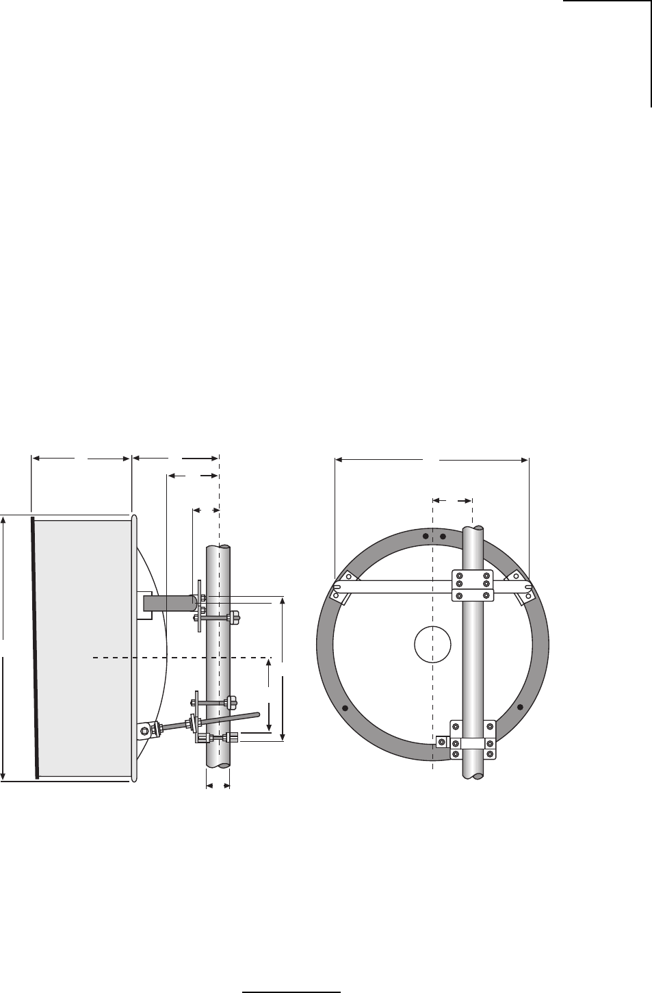
1. For antenna mounting and planning dimensions, see Figure B.1 and Table B.1.
2. The antenna is normally assembled with an elevation adjustment range of +50 degrees to
-5 degrees. By inverting the mount, it can be assembled with a +5 degree to -50 degree
range. In either configuration, the antenna centerline can be offset right or left, relative to
the vertical mast pipe (See Figure B.2) by inverting the Horizontal Tube Assembly.
Figure B.1 - Two Foot Diameter Antenna
WL035927
JH
B
A
P
K
G
Q
D
C

B-2
N2-X Ethernet Extender Installation and Operation Manual
Table B.1 - Two Foot Diameter Antenna Dimensions
noisnemiDnoitpircseDannetnA)mm6.0(.tf2annetnA)mm8.0(.tf5.2
AhtgneLtnuoM)mm075("4.22)mm017("9.72
BtnioPtoviP)mm501("2.4)mm501("2.4
CtesffOeniLretneC)mm521("0.5)mm521("0.5
DturtStnuoMlatnoziroHA/NA/N
EturtStnuoMlacitreV.tP.tvP)mm571("8.8)mm012("3.8
FturtSediSdexiFlatnoziroHA/NA/N
GenilretneCannetnA)mm543("6.31)mm524("8.61
HhtgneLrotcelfeR)mm513("3.21)mm063("3.41
JhtgneLduorhStrohS)mm023("5.21)mm063("3.41
htgneLduorhSgnoL)mm583("1.51)mm053("8.51
KretemaiDannetnA)mm537("0.92)mm098("53
L)dradnatS(htgneLemodaR)mm043("4.31)mm524("8.61
NhtpeDturtStnuoMA/NA/N
PxetreVrotcelfeR)mm091("6.7)mm022("7.8
QretemaiDtsaM)mm511-06("5.4"4.2)mm511-06("5.4"4.2
egnaRelbatsujdAhtumizA°5-/+°5-/+
segnaRtnemtsujdAnoitavelE°5-/°05+°5-/°05+
829530LW
B-3
N2-X Ethernet Extender Installation and Operation Manual
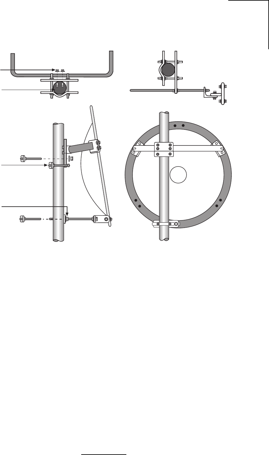
Figure B.2 - Mount Configuration
WL035929
and Nut (4)
3/8” (10mm)
Round Head
Screw Lockwasher
ø 2.4”- 4.5”
(60-115mm)
Shear Stop
Collar
Elevation
Plate

B-4
N2-X Ethernet Extender Installation and Operation Manual
Table B.2a- Contents List, Reflector Assembly
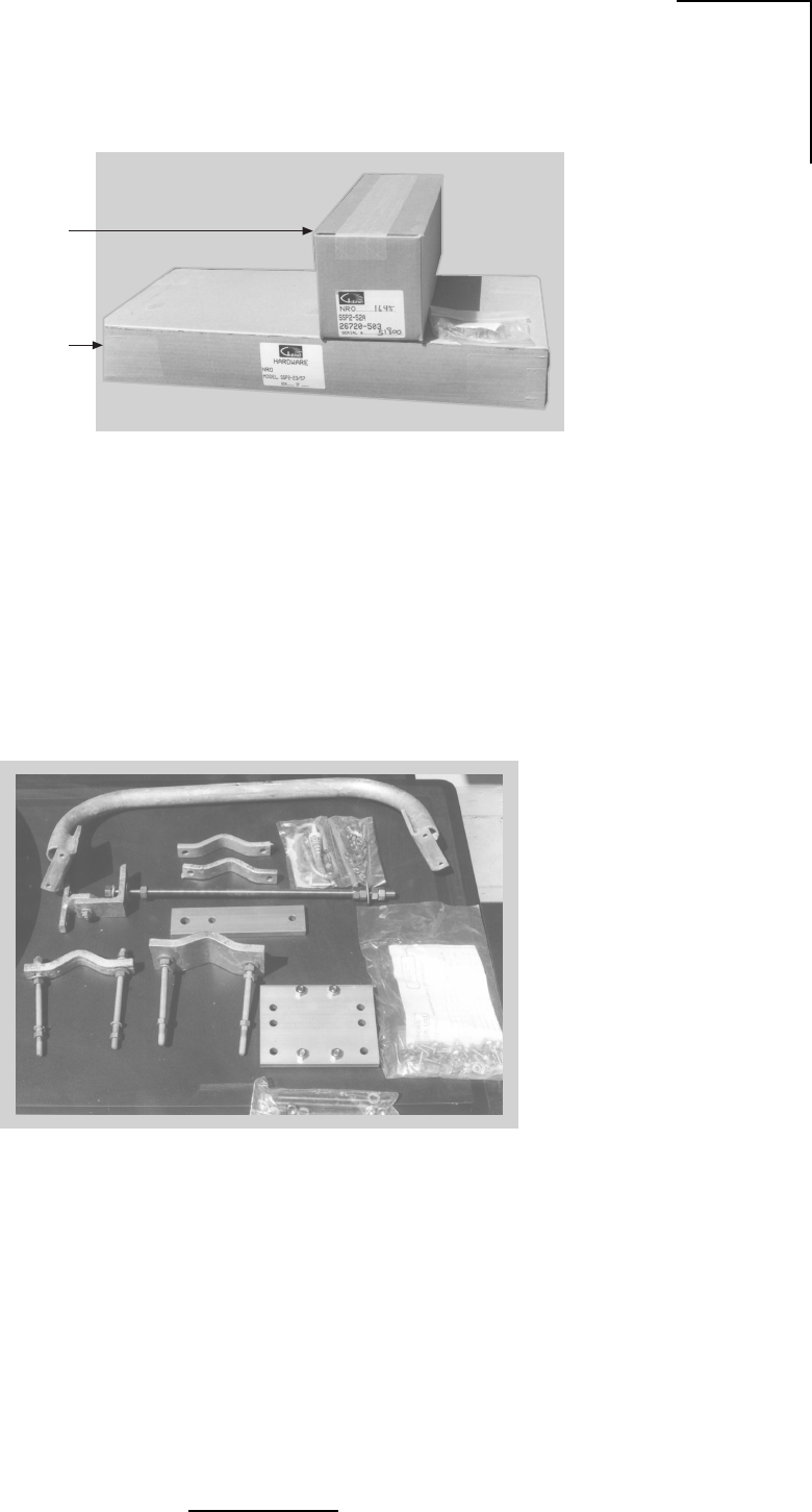
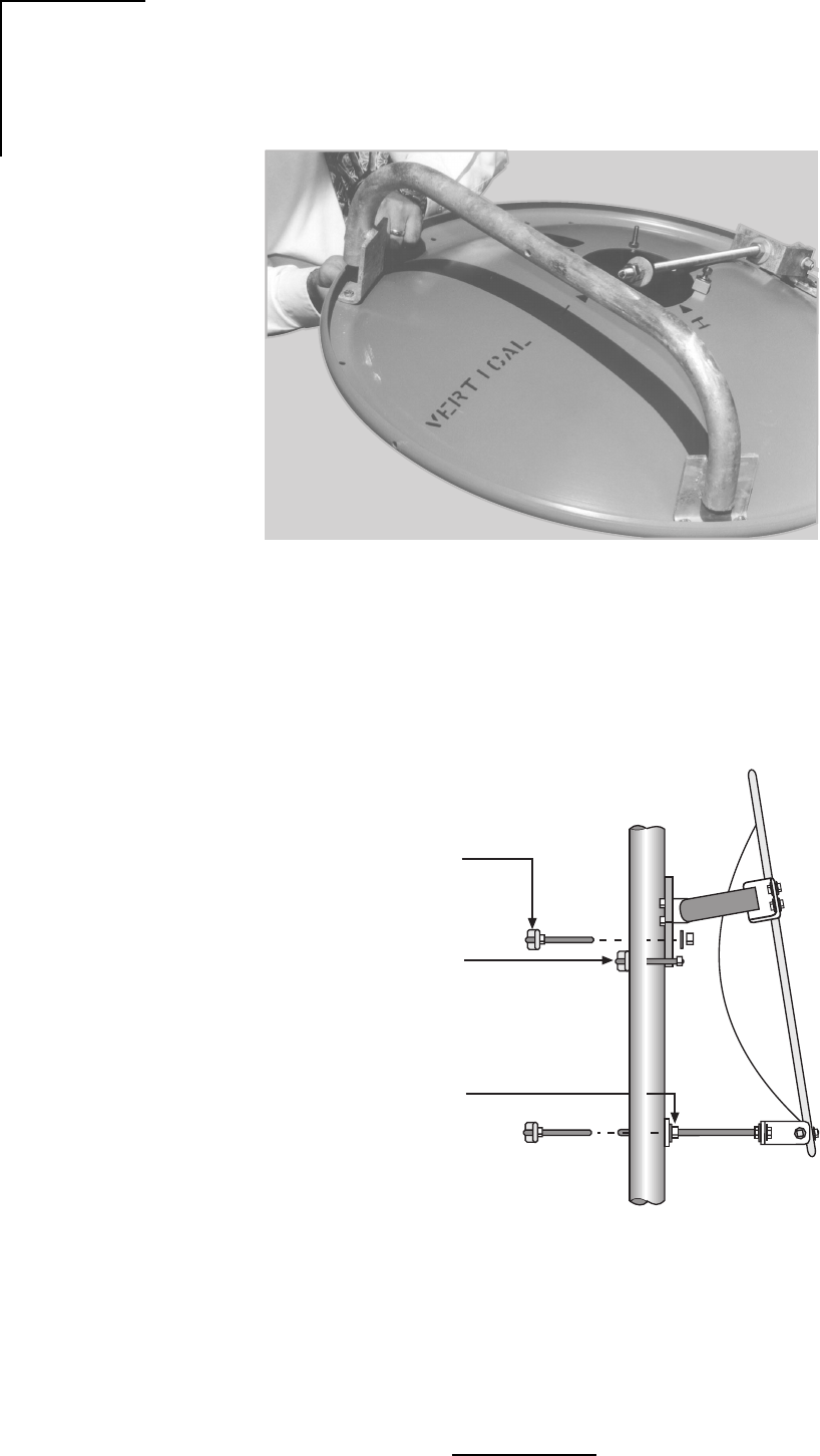
Unpacking and Preparation
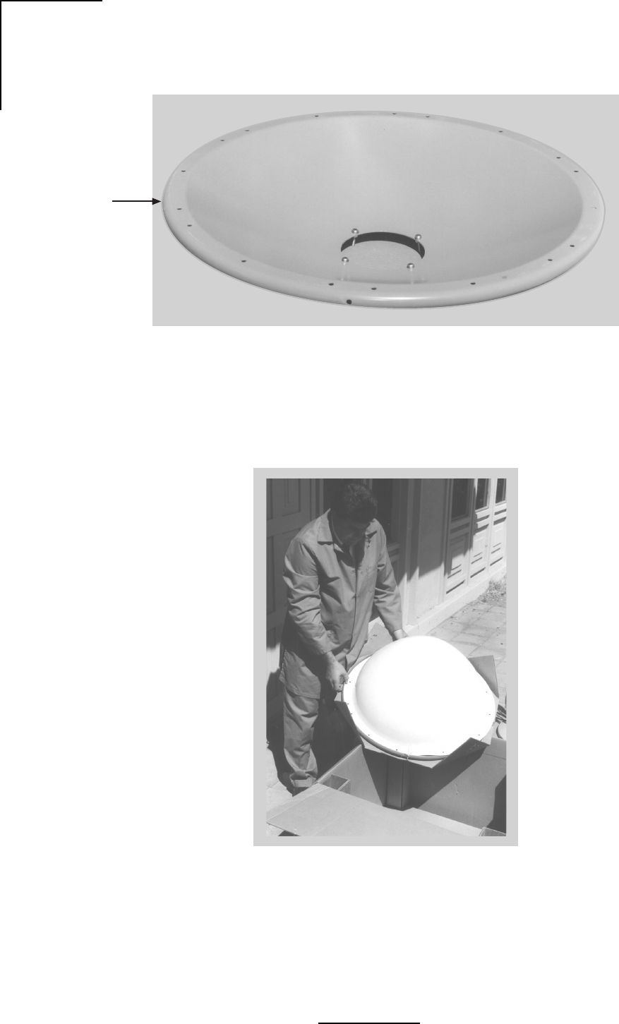
1. Carefully unpack the reflector, mount, shroud (if any), radome (if any) and feed from the
crate. For correct antenna performance, handle all components with care. Set aside the
packaged feed and any shroud or radome. See Figures B.3 through B.6.
Caution: The reflector spinning has been formed to a very close-toleranced parabolic shape.
Careful handling and assembly is required to avoid denting or deforming the reflector,
which would degrade the antenna's performance.
2. Inspect for any damaged parts. See Tables B.2a-B.2d for an inventory of the parts and
hardware shipped with the antenna.
Shroud Attachment
Attach the shroud assembly that is provided with high-performance antennas to the reflector.
The installation procedure is covered by another instruction sheet supplied with the shroud.
Note: Some models have the shroud factory installed.
Table B.2b- Contents List, Feed Assembly
rebmuNtraPnoitpircseD.ytQkcehC
3-23832A2-nepO'2ES.yssA.lfeR1
039530LW
rebmuNtraPnoitpircseD.ytQ
1-63752pmalCgnitnuoMdeeF4
305-61762058.5-052.5A/SdeeF1
0715TDA071SSD'04x8//7x61/3lytuBkcarTRR1
0500XWF560.x437.0W"4/1rehsaW4
122-IIsnoitcurtsnInoitallatsnI1
0600XUNtuNxeH4
0500XWSrehsaWtilpS4
139530LW
B-5
N2-X Ethernet Extender Installation and Operation Manual
Figure B.3 - Mounting Hardware Packed
Figure B.4 - Mounting Hardware Unpacked
WL035932
Feed Horn
Assembly
Mounting
Hardware
WL035933

B-6
N2-X Ethernet Extender Installation and Operation Manual
Table B.2c- Contents List, Mount Assembly
rebmuNtraPnoitpircseDytQ
105-57652ylbmessAepiPlatnoziroH 1
505-52752ylbmessAgnipmalCtsaM 1
2-61322vlaGdoRdedaerhT2
5-52542"1flaHpmalCtsaM1
0210GWFvlaGrehsaW2
1210GUNvlaGrehsaW6
0900GWSvlaGrehsaWtilpS4
905-52732yssAgnipmalCtsaM 1
2-61322vlaGdoRdedaerhT2
8-52542flaHpmalCtsaM1
0210GWFvlaGrehsaW2
0210GUNtuNxeH6
0900GWSvlaGrehsaWtilpS4
405-72752yssApotSraehS 1
3-58232doRdedaerhT2
2-52542trohS-flaHpmalCZA2
0310XUNtuNxeH6
0900GWSvlaGrehsaWtilpS4
305-03752yssAdoRnoitavelE 1
6-11632doRnoitavelE1
105-24832yssAtkrBdoRnoitavelE1
1-66652elgnAtroppuSnoitavelE1
0800GOBvlaGtloBxeH1
0210GWFvlaGrehsaW1
0410GWFvlaGrehsaW1
0210GUNvlaGtuNxeH1
5910XUNSStuNxeH4
0900GWSvlaGrehsaWtilpS1
0010GWSvlaGrehsaWtilpS1
439530LW

B-7
N2-X Ethernet Extender Installation and Operation Manual
Table B.2d- Contents List, Mount Assembly
rebmuNtraPnoitpircseD.ytQ
105-33752 tiKerawdraHtnuoM1
45-94701.vlaGtloB-U2
2-16532recapS2
5000MDAebuT.zo1ezieS-itnA1
1290XOBtloBxeH6
0210GWFrehsaW4
05000XWFrehsaW21
0210GUN.vlaGtuNxeH4
0600XUN.vlaGtuNxeH6
0900GNPtunlaP4
0500XWS.vlaGrehsaWtilpS6
1-09562 etalPnoitavelE1
1-19562 etalPhtumizA1
6811XOB wercSDHDNR4
0310XUN tuNxeH4
0800XWS rehsaWtilpS4
232-II snoitcurtsnInoitallatsnI1
539530LW
B-8
N2-X Ethernet Extender Installation and Operation Manual
Figure B.5 - Parabolic Reflector
Figure B.6 - Unpacking the Radome
WL035936
Parabolic
Reflector
WL035937
B-9
N2-X Ethernet Extender Installation and Operation Manual
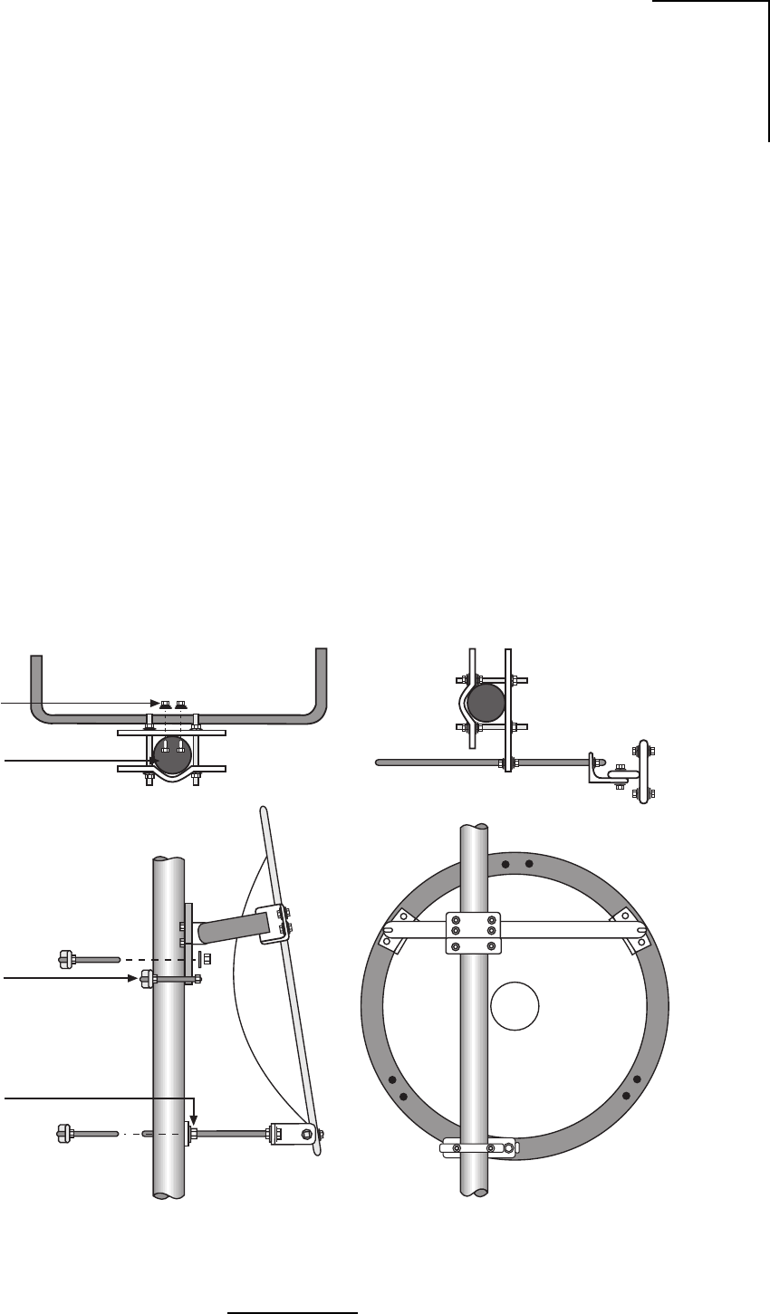
Figure B.7 - Antenna Mount Assembly
Mount Assembly and Attachment
1. The reflector should be placed face down, either on the shroud or blocked up on packing
lumber. Locate the Top and Bottom markings stenciled onto the back of the reflector.
2. Loosely attach Top Support Angles to the Horizontal Tube Assembly as shown in Figure
B.7 and B.8.
3. For desired mount configuration (refer to Figure B.2), attach the Vertical Tube Assembly
to the Horizontal Tube Assembly as shown in Figure B.7 and B.8.
4. Verify proper assembly of the elevation rod hardware as shown in Figure B.9. Remove
outer hardware and insert rod through elevation plate.
Important: For elevation angles grater than ±20°, Beveled Washers, shown in Figure B.9,
must be used. However, beveled washers may be used for elevation angles greater than
±10°.
5. Carefully place mount assembly onto antenna backring, taking care not to damage the
reflector. Loosely fasten the Top Support Angles and the Elevation Support Angle to the
antenna backring using 1/2” hardware as shown in Figure B.7.
6. Verify alignment of the Vertical Assembly with the vertical axis of the reflector and secure
the Top Support Angles and the Elevation Support Angle to the ring.
WL035938
and Nut (4)
3/8” (10mm)
Round Head
Screw Lockwasher
ø 2.4”- 4.5”
(60-115mm)
Shear Stop
Collar
Elevation
Plate
B-10
N2-X Ethernet Extender Installation and Operation Manual
Figure B.9 - Elevation Rod Assembly
Figure B.8 - Antenna Mount Assembly
WL035939
WL035940
Secure Antenna to Mast
Pipe using large and
small Mast Clamps
Attach Shear Stop
Collar on Mast Pipe so
that it will be Under
Azimuth Plate
Position Elevation Plate
on the Mast so elevation
screw is horizontal when
Antenna is aligned
B-11
N2-X Ethernet Extender Installation and Operation Manual
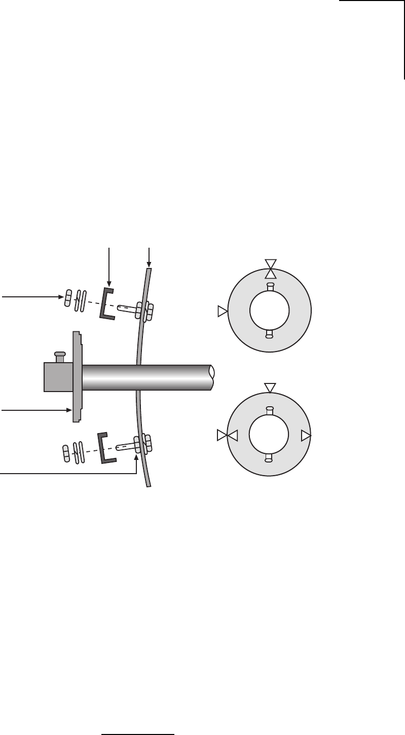
Feed Installation
Following the instructions provided with the feed assembly, install the feed in the reflector. Refer
to Figures B.10 through B.14.
Figure B.10 - Feed Horn Installation
Clamp
1/4”-20
Hex Nut
Horizontal
H
V
Graphite
Grease
Hex Nut,
Lockwasher,
Flat Washer
Feed
Support Reflector
H
V
Vertical
WL035941
B-12
N2-X Ethernet Extender Installation and Operation Manual
Figure B.11 - Feed Horn Polarization Markings
Figure B.12 - Parabola Rear View Showing Polarization Reference Markers
WL035942
Feed Horn
Polarization
Markings
WL035943
Horizontal
Polarization
Marking
Vertical
Polarization
Marking
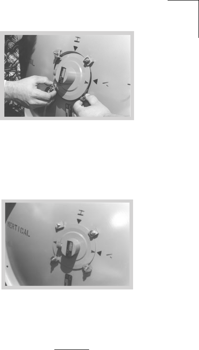
B-13
N2-X Ethernet Extender Installation and Operation Manual
Figure B.13 - Feed Horn Installation
Figure B.14 - Feed Horn Installation for Vertical Polarized Operation
WL035945
WL035944
B-14
N2-X Ethernet Extender Installation and Operation Manual
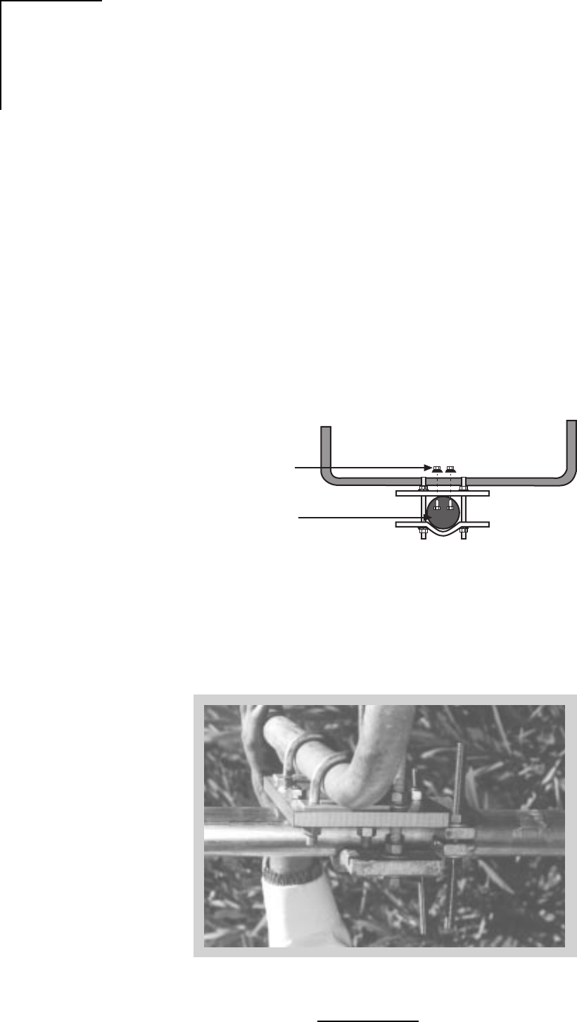
Figure B.16- Azimuth Adjustment Clamp Assembly
Radome Installation
Molded Radomes (normally optional on standard antennas) should be installed following the
instructions provided.
Azimuth Adjustment Clamp/Shear Stop Installation
1. Verify proper assembly of the azimuth clamp/shear stop clamp as shown in Figure B.15
and B.16. Securely attach the shear stop clamp to the mast pipe as shown, orienting it as
nearly as possible to the antenna boresight direction, and square to the mast axis. Note
that the shear stop clamp used on the two foot antennas also provides the azimuth
adjustment.
2. Refer to Figure B.1 for the position of the antenna centerline relative to the shear stop
clamp. The clamp must be mounted to provide support during installation and azimuth
adjustment.
Figure B.15 - Azimuth Clamp/Shear Stop Assembly
3/8” (10mm)
Round Head
Screw Lockwasher
and Nut (4)
ø 2.4” - 4.5”
(60-115mm)
WL035946
WL035947
B-15
N2-X Ethernet Extender Installation and Operation Manual
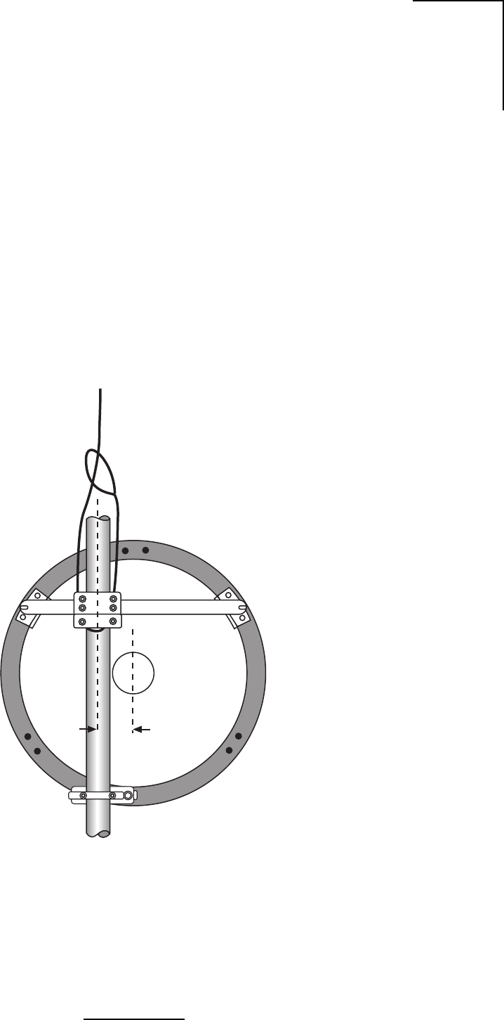
Antenna Hoisting and Installation
1. Attach a hoist strap around the vertical assembly or the horizontal assembly as shown in
Figure B.17. Do not hoist by the elevation rod. Make sure that the vertical assembly is
unobstructed where it will mount against the mast pipe.
2. Attach tag lines and carefully lift the antenna into position, resting the vertical assembly on
the shear stop clamp.
3. Fasten the mount to the mast pipe with 1/2” U-bolts. The antenna must be free to rotate
during azimuth adjustment, so tighten only enough to close the gap between the mast and
vertical channel. Do not leave the antenna loose for any extended period of time, i.e.
overnight.
Figure B.17- Hoisting the Antenna
WL035948
5”
(127mm)

B-16
N2-X Ethernet Extender Installation and Operation Manual
General Antenna Alignment Procedures
Normally the antenna is aligned by performing azimuth and elevation adjustments and
elevation adjustments as necessary until the peak signal is obtained. It may be helpful to re-
peak one adjustment before finalizing or locking down the other. See Figure B.18.
Warning: Damage to the antenna can occur if azimuth or elevation adjustments are
attempted without loosening the proper connections as described in the following steps.
Azimuth Adjustment
1. Be sure the mast pipe U-bolts are just loose enough to allow mount rotation while
maintaining complete contact between the mount and the mast pipe.
2. Turn the long stainless steel azimuth screws against the mounting channel. By alternately
turning one azimuth adjustment screw out and the other in, the antenna can be rotated to
the desired azimuth angle. Approximately 1 turn changes the azimuth direction by 1°. Avoid
adjusting the antenna beyond the ±5° provided by the azimuth clamp as this can damage
the adjusting hardware. Fasten the antenna to the mast pipe and reposition the clamp if
needed.
Note: By securing the mount to the mast pipe and realigning the azimuth clamp with the
antenna boresight, more reliable and precise azimuth adjustments can be achieved.
After all adjustments are made, tighten both of the azimuth screws against the channel and
secure with the lock nuts provided.
3. Tighten the mast pipe U-bolts while maintaining the peak signal by alternating from left to
right in 1/4 turn intervals.
Figure B.18 - Antenna Alignment using RSL Output while Adjusting the Antenna
WL035949

B-17
N2-X Ethernet Extender Installation and Operation Manual
Elevation Adjustment
1. Insure that both of the bolts connecting the mount to the Top Support Angles and the
pivoting Elevation Angle (refer to Figures B.7 and B.9) are just loose enough to allow
resisted rotation. See Figure B.18.
2. Back the outer nuts on the elevation rod away from the bottom mount plate to allow some
fine adjustment range.
3. Turn the inside nut (with flat washer) on the elevation rod to adjust the elevation angle.
Approximately 5 turns changes the elevation by 1°. Remember, for elevation greater than
20°, install the two beveled washers as shown in Figure B.9.
4. After all adjustments are made, lock the nut against the bottom mount plate. Tighten the
angle pivot bolt and support bracket bolts.
Important: Be sure to tighten all hardware after final adjustments and insure that split
lockwashers, palnuts, or jam nuts are used where provided.

B-18
N2-X Ethernet Extender Installation and Operation Manual
Table B.3 - Nut Tightening Procedures
Inspection and Maintenance
1. Before leaving the installation, check that all hardware on the mount, shroud, radome, and
feed is tight and that nuts are locked in place.
2. Inspection of the antenna should be performed at lease once a year to check its condition
and to insure safe operation and maintenance. Qualified personnel, knowledgeable and
experienced in antenna installations, are required for this inspection.
Supplemental Information
Table B.3 is provided for installers unfamiliar with adequate nut tightening procedures for use
on stainless steel bolts, U-bolts, galvanized bolts or any bolts without the ASTM-”A325” marking
on the head. Disregard these recommendations when specific tightening requirements are
given.
Note: It is not recommended to reuse a palnut that has already been fully tightened or
deformed in any way. It should be replaced by a new palnut.
Weather Proofing the Type N Female Connector on Feeds
Remove the protective cover from the end of the feed and mate the connectors, screwing the
male connector firmly onto the feed.
Important: After connecting the coaxial cable, wrap the Type N connector with the gray butyl
rubber, squeezing it firmly around all joints to make a continuous seal. Finish the
weatherproofing by wrapping the butyl rubber with several layers of black PVC tape (not
supplied).
eziStloBlanimoNeuqroTtuNeuqroTtunkcoLtunlaP
"4/1.bl/.ni05.bl/.ni04
"61/5.bl/.ni201.bl/.ni06
"8/3.bl/.tf51.bl/.ni58
"61/7 .bl/.tf42 .bl/.tf51
"2/1.bl/.tf73.bl/.tf61
"8/5.bl/.tf47.bl/.tf82
"4/3.bl/.tf571.bl/.tf44
"8/7.bl/.tf212.bl/.tf15
"1.bl/.tf813.bl/.tf95
059530LW
C-1
N2-X Ethernet Extender Installation and Operation Manual
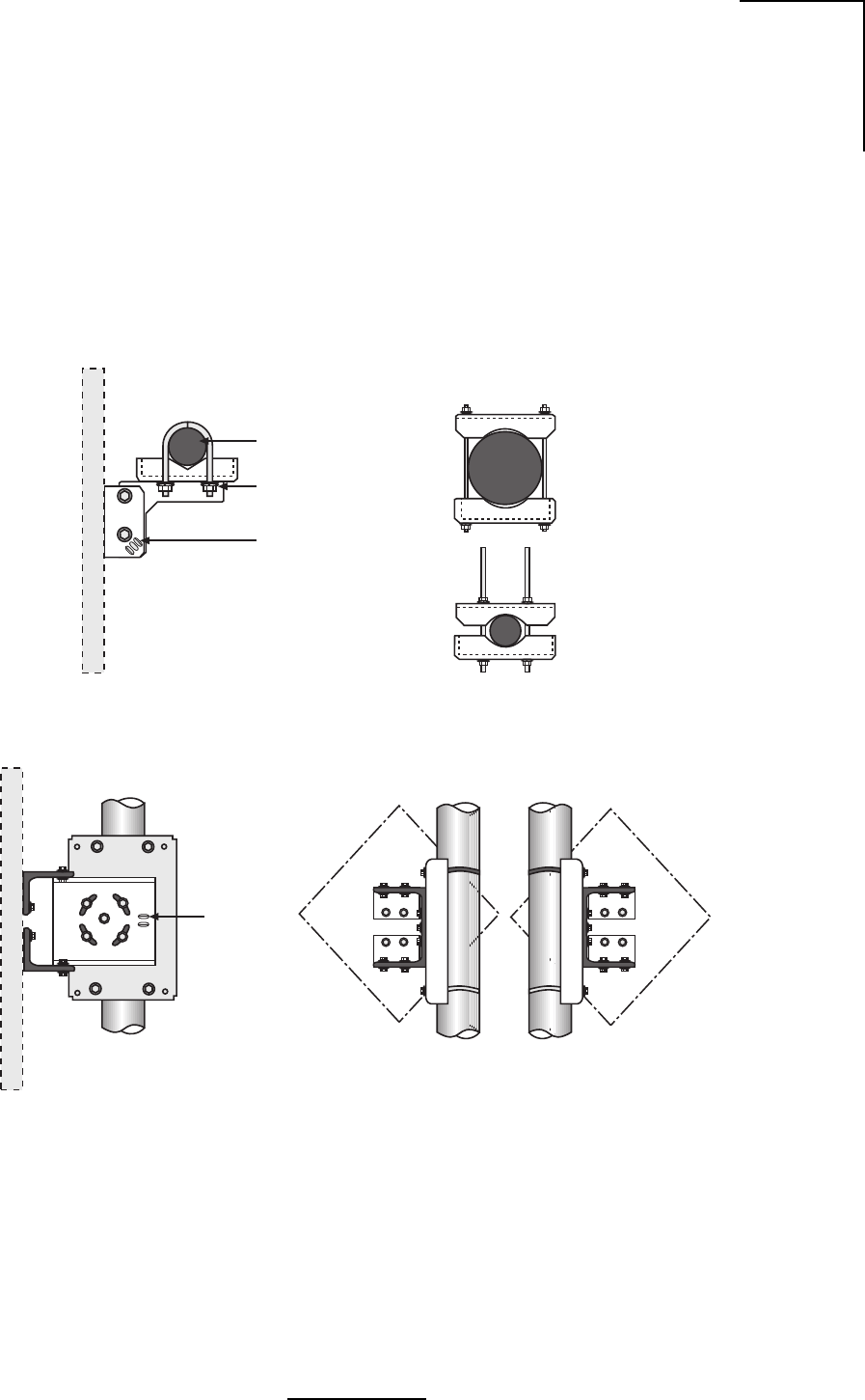
Appendix C Adjustable Panel Antenna Mount
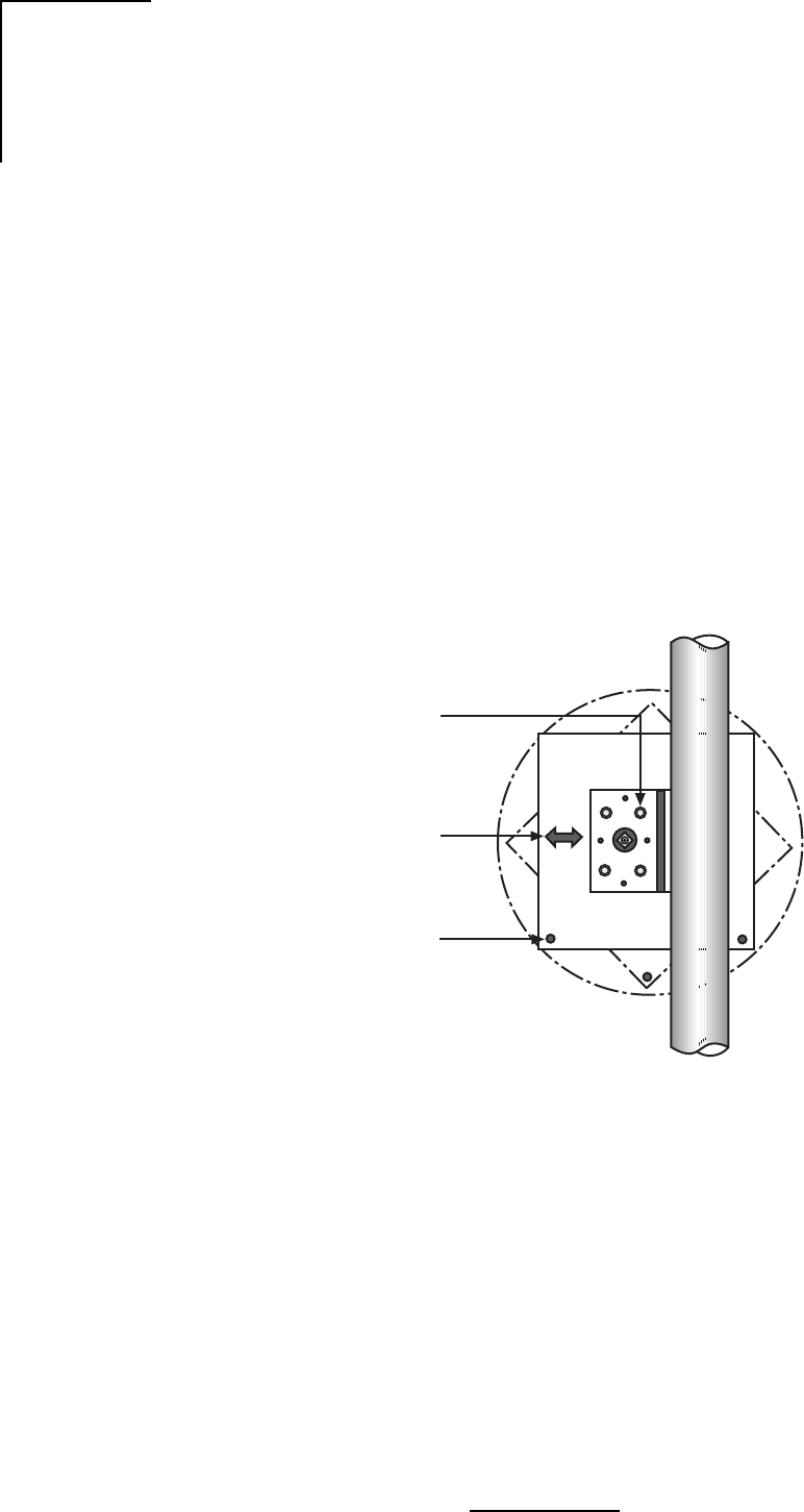
Assemble the panel mount according to Figure C.1. Orient Antenna using instructions supplied
with the antenna. Antenna models used with this mount may be circular, square or diamond
shaped. To change the offset of the antenna, unbolt the mount from the antenna, invert the
mount and reattach to the antenna.
Figure C.1 - Antenna Mount
2 3/8” (60mm)
DIA Mast
(2) 1/4” U-Bolt w/
Washer, Lockwashers
and Nuts
Azimuth Adjustment
Slots
Top View Optional Mast Clamp Kit
for 1.9” (48mm) DIA thru
4.5” (114mm) DIA Masts
Side View
Elevation
Adjustment
Slots
Rear View
Offset Left Rear View
Offset Right
WL035951
C-2
N2-X Ethernet Extender Installation and Operation Manual
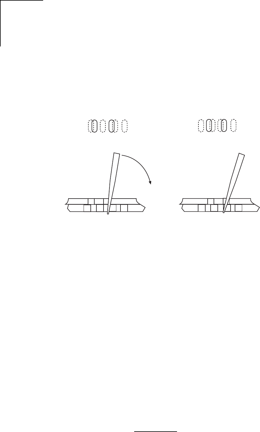
Loosen the azimuth or elevation locking hardware while maintaining sufficient friction to prevent
unwanted slippage. See Figure C.2.
Insert flat blade screw driver into slot “B” and pry in direction of the arrow or into slot “A” and pry
in opposite direction, as shown in Figure C.2. Stop prying approximately as new overlapping
slot in bottom plate becomes sufficiently visible when viewed through slot “A”.
Figure C.2 - Azimuth and Elevation Planning
ABAB
Top View
Sectional View
Sectional View
Top View
WL035952
ABAB
C-3
N2-X Ethernet Extender Installation and Operation Manual
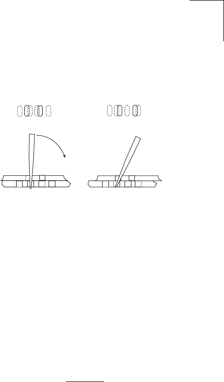
Insert Screw Driver into slot “A” and pry in direction of the arrow, as shown in Figure C.3. Stop
prying approximately as new slot in bottom plate becomes sufficiently visible when viewed
through slot “B”. Continue alternating slots and prying in either direction until desired alignment
is obtained. Lock down hardware securely before leaving the site.
Figure C.3- Azimuth and Elevation Planning
AB
AB
Top View
Sectional View
WL035953
AB
AB
Sectional View
Top View
C-4
N2-X Ethernet Extender Installation and Operation Manual
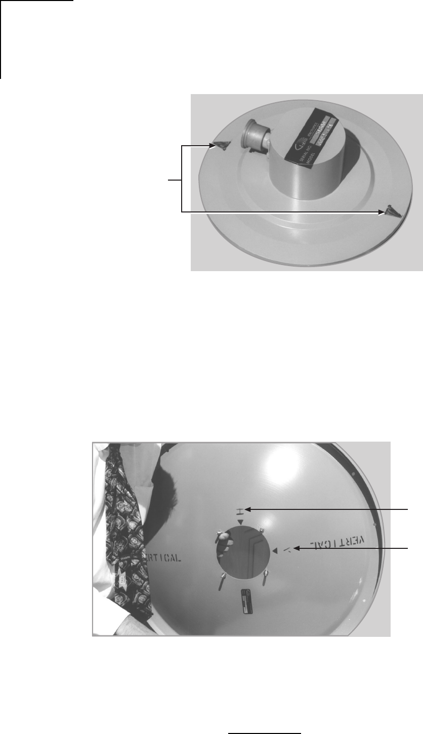
Attach the antenna to the mount as shown in Figure C.4. For antenna polarization, assemble
the antenna to the mount using four sets of nuts and washers after desired polarization is
selected. In horizontal polarization the arrow sticker should be pointed in a horizontal direction.
Likewise, in vertical polarization the arrow sticker should be pointed in a vertical position.
Important: After cable connection is completed, wrap connection with Butyl or other
waterproof tape, supplied by the customer.
Each panel antenna has four factory sealed drain holes located on the back of the antenna. After
orienting the antenna to its proper polarization, the lower most sealed drain hole(s) must be
punctured with a pointed tool. See Figure C.4.
Caution: Do not allow the tool to protrude into the drain hole more than 1/4” (7mm) or damage
to the antenna may result.
Figure C.4 - Flat Panel Antenna
WL035954
Drain
Holes
Polarization
Arrow
Antenna
Polarization
using Nuts
and Washers
C-5
N2-X Ethernet Extender Installation and Operation Manual
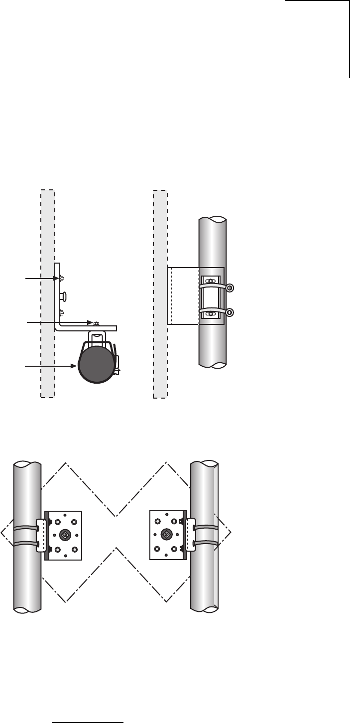
Aim the antenna according to Figure C.5. Orient the antenna using instructions supplied with
the antenna. Antenna models used with this mount may be circular, square or diamond shaped.
To change the offset, unbolt the mount from the antenna, then invert the mount and reattach
in the antenna.
Figure C.5 - Adjustable Panel Antenna Mount
Rear View
Right Offset Rear View
Left Offset
Side View
Clamp Kit for
1.9 (48mm) DIA
Thru 4.5 (114mm)
DIA Masts
1/4” Carriage Bolts
w/ Washers, Lockwashers
and Nuts (2)
Elevation
Adjustment
WL035955

C-6
N2-X Ethernet Extender Installation and Operation Manual