Wireless N2X5-3S1-16B User Manual Manual update in response to 22 Nov information request
Wireless Inc Manual update in response to 22 Nov information request
Wireless >
Contents
- 1. n2xusersMANUAL
- 2. Manual update in response to 22 Nov information request
- 3. Dec 17 draft pdf version
- 4. Additional corrections to 17 Dec draft
- 5. Gabriel flat panel antenna description
Manual update in response to 22 Nov information request
Page 1 of 3
Please make the following changes to the N2-X Ethernet Extender Manual:
Change antenna gain numbers (dBi) in Table 3.1 to values shown below, and add text between table
heading and table as shown:
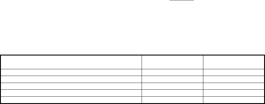
Table 3.1 - Maximum Transmit Power Level Setting vs. Antenna Type (for compliance with FCC
EIRP limits) in the 5.3 GHz band
Per the following table, in the 5.3 GHz band the highest power setting (approximately +12 dBm) can only
be installed with the lowest gain antenna which is the 6” Flat Panel Plane Polarized (DFPD.5-52) with 17.5
dBi. Each radio is shipped from the factory with a standard 6’ coaxial cable for connection between the
radio and the antenna. The cable has a nominal loss of approximately 2.6 dB.
UNII radios are covered under CFR 47 FCC part 15, 15.407 Subpart E. 15.407.a.2 which states
Ptransmit = 11 dBm + 10 log B where B is the -26 dB BW with a 6 dBi antenna. Above 6 dBi antenna gain
there is a 1:1 reduction in Ptransmit to maintain the same MAXIMUM EIRP. This is accomplished by the
changes in output power setting for the alternative antennas.
The FCC EIRP limit for the 5.3 GHz band with our transmitter bandwidth is +28 dBm. With the transmit
power set to +12 dBm, the EIRP with the 6” Flat Panel antenna, and standard 6’ coaxial cable will be:
12 dBm + 17.5 dBi –2.6 dB = 26.9 dBm.
Antenna Type Manufacturer P/N Maximum Transmit
Power Setting (dBm)
2’ diameter dish with radome, Plane Polarized, 28.1 dBi Gabriel SSP2-52ARI 0
2’ diameter dish with radome, Dual Polarized, 28.1 dBi Gabriel SSD2-52ARI 0
6” Flat Panel, Plane Polarized, 17.5 dBi Gabriel DFPD.5-52 +12
12” Flat Panel, Plane Polarized, 23 dBi Gabriel DFPD1-52 +4
24” Flat Panel, Plane Polarized, 27.5 dBi Gabriel DFPD2-52 0
Page 2 of 3
Please insert the following in section 2.3 on page 10 between the last paragraph in the text that describes
the “outdoor unit” interfaces and Table 2.4. This is a duplicate of the above statements.
Table X.X - Maximum Transmit Power Level Setting vs. Antenna Type (for compliance with FCC
EIRP limits) in the 5.3 GHz band
Per the following table, in the 5.3 GHz band the highest power setting (approximately +12 dBm) can only
be installed with the lowest gain antenna which is the 6” Flat Panel Plane Polarized (DFPD.5-52) with 17.5
dBi. Each radio is shipped from the factory with a standard 6’ coaxial cable for connection between the
radio and the antenna. The cable has a nominal loss of approximately 2.6 dB.
UNII radios are covered under CFR 47 FCC part 15, 15.407 Subpart E. 15.407.a.2 which states
Ptransmit = 11 dBm + 10 log B where B is the -26 dB BW with a 6 dBi antenna. Above 6 dBi antenna gain
there is a 1:1 reduction in Ptransmit to maintain the same MAXIMUM EIRP. This is accomplished by the
changes in output power setting for the alternative antennas.
The FCC EIRP limit for the 5.3 GHz band with our transmitter bandwidth is +28 dBm. With the transmit
power set to +12 dBm, the EIRP with the 6” Flat Panel antenna, and standard 6’ coaxial cable will be:
12 dBm + 17.5 dBi –2.6 dB = 26.9 dBm.
Antenna Type Manufacturer P/N Maximum Transmit
Power Setting (dBm)
2’ diameter dish with radome, Plane Polarized, 28.1 dBi Gabriel SSP2-52ARI 0
2’ diameter dish with radome, Dual Polarized, 28.1 dBi Gabriel SSD2-52ARI 0
6” Flat Panel, Plane Polarized, 17.5 dBi Gabriel DFPD.5-52 +12
12” Flat Panel, Plane Polarized, 23 dBi Gabriel DFPD1-52 +4
24” Flat Panel, Plane Polarized, 27.5 dBi Gabriel DFPD2-52 0

Page 3 of 3
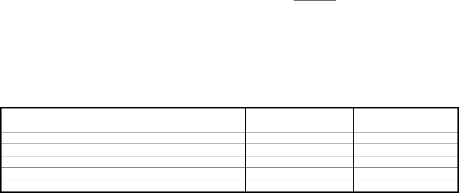
Table X.X - Maximum Transmit Power Level Setting vs. Antenna Type (for compliance with FCC
EIRP limits) in the 5.7 GHz band, original and July 31, 1998 rules
Per the following table, in the 5.7 GHz band the highest power setting (approximately +12 dBm) can only
be installed with the lowest gain antenna which is the 6” Flat Panel Plane Polarized (DFPD.5-52) with 17.5
dBi. Each radio is shipped from the factory with a standard 6’ coaxial cable for connection between the
radio and the antenna. The cable has a nominal loss of approximately 2.6 dB.
UNII radios are covered under CFR 47 FCC part 15, 15.407 Subpart E. 15.407.a.3 which states
Ptransmit = 17 dBm + 10 log B where B is the -26 dB BW with a 6 dBi antenna. Above 6 dBi antenna gain
there is a 1:1 reduction in Ptransmit to maintain the same MAXIMUM EIRP. This is accomplished by the
changes in output power setting for the alternative antennas.
The original FCC EIRP limit for the 5.7 GHz band with our transmitter bandwidth is +33 dBm. With the
transmit power set to +12 dBm, the EIRP with the 6” Flat Panel antenna, and standard 6’ coaxial cable will
be: 12 dBm + 17.5 dBi –2.6 dB = 26.9 dBm. The corresponding settings are included in the following table.
Antenna Type Manufacturer P/N Maximum Transmit
Power Setting (dBm)
2’ diameter dish with radome, Plane Polarized, 28.1 dBi Gabriel SSP2-52ARI 0
2’ diameter dish with radome, Dual Polarized, 28.1 dBi Gabriel SSD2-52ARI 0
6” Flat Panel, Plane Polarized, 17.5 dBi Gabriel DFPD.5-52 +12
12” Flat Panel, Plane Polarized, 23 dBi Gabriel DFPD1-52 +8
24” Flat Panel, Plane Polarized, 27.5 dBi Gabriel DFPD2-52 +4
The FCC will also allow higher EIRP for point to point links with higher gain antennas. Page 703 of the
FCC document, CFR 47 FCC part 15, 15.407 Subpart E, FR 40836, July 31, 1998 has the provisions for
these power limits. The path length isn’t increased, since the 5.3 GHz transmitter isn’t allowed the higher
EIRP. We recommend the higher power settings only when absolutely necessary.
This rule states " fixed pt-pt U-NII devices operating in this band may employ transmitting antennas with
directional gain up to 23 dBi without the corresponding reduction in transmitter peak output power or peak
power spectral density”. Also above 23 dBi antenna gain there is a 1:1 reduction in Pout to maintain the
same MAX EIRP.
We are in compliance even at the maximum antenna gain and transmitter power, since the
corresponding output power is over +27 dBm in our BW and the resulting EIRP for a 6 dBi antenna is +33
dBm. This EIRP limit is further extended to +44 dBm by a +23 dBi antenna. Our EIRP with a 23 dBi
antenna at maximum output power is 12 dBm + 23 dBi –2.6 dB = +32.4 dBm. With the highest gain
antenna and maximum output power the EIRP would be 12 dBm + 28.1 dBi –2.6 dB = +37.5 dBm.